

Operation Approval for Commercial Airborne Wind Energy Systems


1
Faculty of Aerospace Engineering, Delft University of Technology, 2629 HS Delft, The Netherlands
2
European Space Research and Technology Centre, European Space Agency, 2200 AG Noordwijk, The Netherlands
*
Author to whom correspondence should be addressed.
Energies 2023, 16(7), 3264; https://doi.org/10.3390/en16073264
Submission received: 1 February 2023
/
Revised: 19 March 2023
/
Accepted: 3 April 2023
/
Published: 5 April 2023
(This article belongs to the Special Issue Airborne Wind Energy Systems)
Abstract
:Integrating the operation of airborne wind energy systems safely into the airspace requires a systematic qualification process. It seems likely that the European Union Aviation Safety Agency will approve commercial systems as unmanned aircraft systems within the “specific” category, requiring risk-based operational authorization. In this paper, we interpret the risk assessment methodology for airborne wind energy systems, going through the ten required steps of the recommended procedure and discussing the particularities of tethered energy-harvesting systems. Although the described process applies to the entire field of airborne wind energy, we detail it for a commercial flexible-wing airborne wind energy system. We find that the air risk mitigations improve the consolidated specific assurance and integrity level by a factor of two. It is expected that the framework will increase the safety level of commercial airborne wind energy systems and ultimately lead to operation approval.
1. Introduction
Airborne wind energy systems (AWES) employ kites or tethered aircraft to harvest wind energy at heights beyond the reach of conventional wind turbines. The access to this so-far unused wind resource, the substantially decreased material use, and the increased capacity factor render the technology a potentially important candidate for a future low-carbon energy economy [1,2].
On the other hand, the development faces technical and non-technical challenges. A prominent example is the robust and reliable control of lightweight but heavily loaded tethered flying devices exposed to fluctuating wind environments [3,4]. The mechanical connection to the ground couples the flight speed to the wind speed and the tether reeling speed. For AWES operated in crosswind mode, this coupling is particularly strong. Without responsive feedback control, wind gusts can rapidly accelerate the flying devices, leading to an amplification of the aerodynamic loading and potentially to a rupture of the tether or other irreversible damage. In the worst case, such events can result in a loss of the system or harm to people [5]. Most implemented AWES are based on aerodynamic lift such that the flight operation cannot be terminated immediately to react to unexpected situations. Exactly how critical an operational anomaly is depends on the specific AWE technology [6]. Inflatable kites fly slower and can usually be relaunched after emergency or crash landings. Heavier fixed-wing kites fly faster, and a crash landing typically amounts to a total loss of the kite. Another important aspect next to the availability and maintenance cost is the safety of persons, properties, and critical infrastructures on the ground and other airspace users [7,8].
As AWES operate at higher altitudes than conventional wind turbines and their operations are not stationary, the interaction with the aviation system is potentially more intricate. AWES’ introduce risks to third parties in the air, which need to be considered in addition to the risks introduced by wind turbines, such as lightning or fire within the equipment.
Despite the various conceptual differences, the consensus in the industry is that safe and robust operation with a sufficient degree of autonomy is an important prerequisite for a successful market introduction of AWES and acceptance by the public [8,9]. To our knowledge, this target has not yet been achieved, as none of the commercial prototypes have been operated continuously for more than a few days. To become economically viable, AWES must fly autonomously, safely, and reliably.
Even though there is no directly applicable functional and safety standard for AWES, relevant experience from other domains can provide additional insights into AWE and help reach the required level of robustness and safety. However, a traditional consensus-based standard approach is complex when the technology is not yet mature. To be viable, any standard will need an unprecedented level of flexibility [10]. We think that the AWE sector can benefit from the experience of aviation, conventional wind turbine, satellite, and autonomous car industries. Similar to conventional wind turbines, commercial AWES must operate fully automated, day and night; they must be tolerant to unfavorable weather conditions. Marking regulations for wind turbines can be the starting point for the visibility marking of AWES [11].
Regarding the level of autonomy, AWES are comparable to low-earth-orbit (LEO) satellites. Most LEO satellites do not have a permanent data connection with the ground. They transmit data (telemetry) and accept commands (telecommand) only during their passes over the ground stations. Their limited connectivity requires sufficient autonomy to conduct their nominal operations without ground intervention. In addition to the nominal operations, satellites have the autonomy to cope with faults in their subsystems. For faults that cannot be corrected by the satellite, the autonomous system can keep the satellite safe until the ground operator takes corrective actions. Even though the working environment and the disturbances for a spacecraft are different from AWES, a similar level of operational autonomy and fault detection, isolation, and recovery (FDIR) is required for robust operation of commercial AWES. Space companies have their proprietary flight frameworks [12], and there has yet to be an agreed approach for the autonomy of satellites.
Recently, NASA released their flight software framework cFS (core flight system) to the public [13]. This framework is used in many NASA missions and will be the baseline of the Lunar Gateway project, a NASA and ESA cooperation. cFS should not be considered a good flight software framework only for space applications, but also for any application that needs to be robust and highly autonomous. cFS may be considered a well-designed, flight-proven flight software framework alternative for AWES. Using cFS may increase the quality of flight software and speed up the certification process thanks to the provided development artifacts of the framework. There is no a standard approach for the FDIR systems. Different missions apply their specific FDIR architecture. A publicly available FDIR architecture for AWES was presented in [14], building on an architecture that was originally developed for space applications [15]. The SAVOIR-FDIR working group at ESA is working on a FDIR guideline for the system level [16]. Similarly, NASA has its guidelines for the design of FDIR denoted as the Fault Management Handbook [17], which can help the design of FDIR for AWES.
The required autonomy level for AWES is comparable with the Society of Automotive Engineers (SAE) Levels 4 and 5 in autonomous driving terminology. Vehicles that fall into these levels are denoted as highly autonomous vehicles (HAVs). Similar to satellites, HAVs manage subsystem faults autonomously. Even though automotive standards address computer-based system safety, there has yet to be a development standard for SAE levels 4 and 5. Underwriters Laboratories and partners from the industry are currently working on a standard called ANSI/UL 4600, the standard for safety for the evaluation of autonomous products [18].
EASA’s new regulation for UAS certification has three categories, namely “open”, for low risk; “specific”, for increased risk; and “certified”, for the same risk as manned aviation. The “specific” category, defined in EASA’s prototype drone regulation [19], is considered more appropriate for AWES because of its flexibility and holistic approach to various types of unmanned aircraft systems. To facilitate the applications for the “specific” UAS category, the Joint Authorities for Rulemaking on Unmanned Systems (JARUS) working group 6 provided a systematic methodology to define the operation concepts and evaluate the air and ground risks introduced by UAS [20].
The specific operations risk assessment (SORA) is a methodology for the classification of the risk posed by a drone flight in the “specific” category and for the identification of mitigations and safety objectives [21]. The methodology provides a systematic starting point for risk assessment and a foundation for communication with the certification authority. It requires agreeing on each assessment step with the competent authority because of the qualitative nature of the process. Depending on their knowledge of the system and expectations, different parties may interpret the criteria differently. The SORA framework guides the applicant and the competent authority while performing the risk assessment. The responsible authorities can decide to adopt the methodology into their regulations. The categorization of UAS as “open”, “certified”, and “specific” was first proposed by JARUS and then became a norm of EASA. Therefore, the expectation is that the SORA will eventually become the norm of EASA for assessing the airworthiness of “specific” UAS.
An application of the SORA process to UAS for crisis and disaster management was presented in [22]. It was concluded that the methodology for determining the risk level of UAS operations is not fully suitable for this application without prior adaptations. A point of criticism was that the SORA does not account for the highly specific threats that can occur in individual rescue operations. We consider this much less of an issue for AWE because the operation of the flying devices follows a more regular and, thus, predictable pattern.
As most UAS operations today are conducted with a pilot in command, remote-piloted aircraft systems (RPAS) can be regarded interchangeably with UAS. There is no “pilot in control” expected for the commercial AWES. Therefore, pilot or remote crew-related concepts in the SORA, such as “line of sight (LOS) flight” or “see and avoid maneuvers”, are not applicable for commercial AWES. Many mitigations for the air and ground-related risks can be derived if an operator is involved. As this does not apply to commercial AWES operations, other mechanisms that replace the human safety factor are required for the AWES airworthiness certification.
This paper is structured as follows. Section 2 introduces the relevant SORA terminology and its interpretation for AWES. Section 3 defines the coverage of the work according to the risk categories. Section 4 (SORA step 1) introduces an example of a flexible-wing kite system with a hypothetical organization and operation scenario. Section 5, Section 6, Section 7, Section 8, Section 9, Section 10, Section 11, Section 12 and Section 13 go through the SORA steps 2 to 10, interpreting each step for AWES in general, and this specific AWES in particular. Section 14 concludes the paper by providing the main contributions and findings of the study.
2. Methodology
The multi-stage risk assessment model of the SORA categorizes the applicant system into one of the six specific assurance and integrity levels (SAIL). The resulting SAIL number of a system represents the consolidated level of air and ground risks. Then, the operator defines the requirements for a safe flight according to the calculated SAIL category. In the SORA guideline, the SAIL definition is “the level of confidence that the defined UAS operation will stay under control within the boundaries of the intended operation” [20].
A working group of Airborne Wind Europe published a guideline for the safe testing and demonstration of currently developed AWES [23] and an introduction to the SORA for AWE [24]. This guideline and the introduction have been devised based on the process and methodologies described in the SORA guidelines by JARUS [20]. One of the aims of the SORA is to inspire operators and authorities, highlighting the benefits of a harmonized risk assessment methodology. In this direction, the working group cooperates with the AWES developers to establish a concept of operations (CONOPS) for the development of AWES. A CONOPS is a way to group the known risks and acceptable risk mitigations to define the “standard scenarios” to make the scenarios and mitigations reusable for different applicants to avoid repetitive individual approvals for the scenarios. Current operations are at a level of automation where the control of the system can be taken over by a remote pilot whenever required, for example, to initiate an emergency landing. Therefore, the CONOPS describing the flight testing of an AWES fits well with the operation of an UAS. Accordingly, the topics related to the remote crew training and command and control (C2) radio links are applicable. Another aspect is related to the fact that AWES have not yet reached the level of reliability and robustness required for operating large flying devices continuously 24/7 in relevant wind environments [6,25]. Since, at this stage of development, the probability of crashes is still relatively high, the operation must rely on the remote crew for implementing and executing risk mitigation procedures. This requires a well-instructed organization with a well-defined set of procedures to handle abnormal and emergency operating conditions [23]. The Airborne Wind Europe safety working group expects the CONOPS to evolve as AWES during the commercialization. According to the preliminary assessments of the working group, the majority of the operations of the concept for AWE testing and demonstration are currently in the SAIL category II. However, some systems may have a higher ground risk class (GRC) and, for that reason, may have a higher SAIL assessment as SAIL category III [23].
In contrast to the CONOPS and SORA work of Airborne Wind Europe and various AWES developers [23,24], the present study aims for the operation approval of a future commercial use case rather than test operation during the development of the technology.
The SORA does not contain prescriptive requirements, but safety objectives to be met at various levels of robustness commensurate with risk. However, this paper aims to go through the SORA steps and provide generally applicable prescriptive design considerations for AWES. The purpose of these considerations is to find the optimal point in the safety/cost trade-off while taking the priorities and resources of AWE companies into consideration. This study aims to place the AWES solution into the lowest possible SAIL category by proposing technical safety mitigation for the commercialization phase since we presume that EASA’s “specific” category and the SORA process will also be applicable for the final operational approval. The SORA and the considerations below are to assess and mitigate the ground and air safety risks of commercial AWES. The main target of this study is not improving the reliability, robustness, or availability of the AWES (even though it may help), but assessing and reaching the required level of safety for AWES.
Potential damage to critical infrastructure harm sensitivity differs from country to country [20]. In the ground risk assessment step, mitigation is proposed to deduct the resulting ground risk. However, for the residual ground risk, the SORA does not provide the means for the required infrastructure safety. Therefore, handling the critical infrastructure harm risk is not in the scope of this paper. System developers are responsible for managing the risk of crashing into critical infrastructures by taking additional measures or defining the commercial operation site constraints.
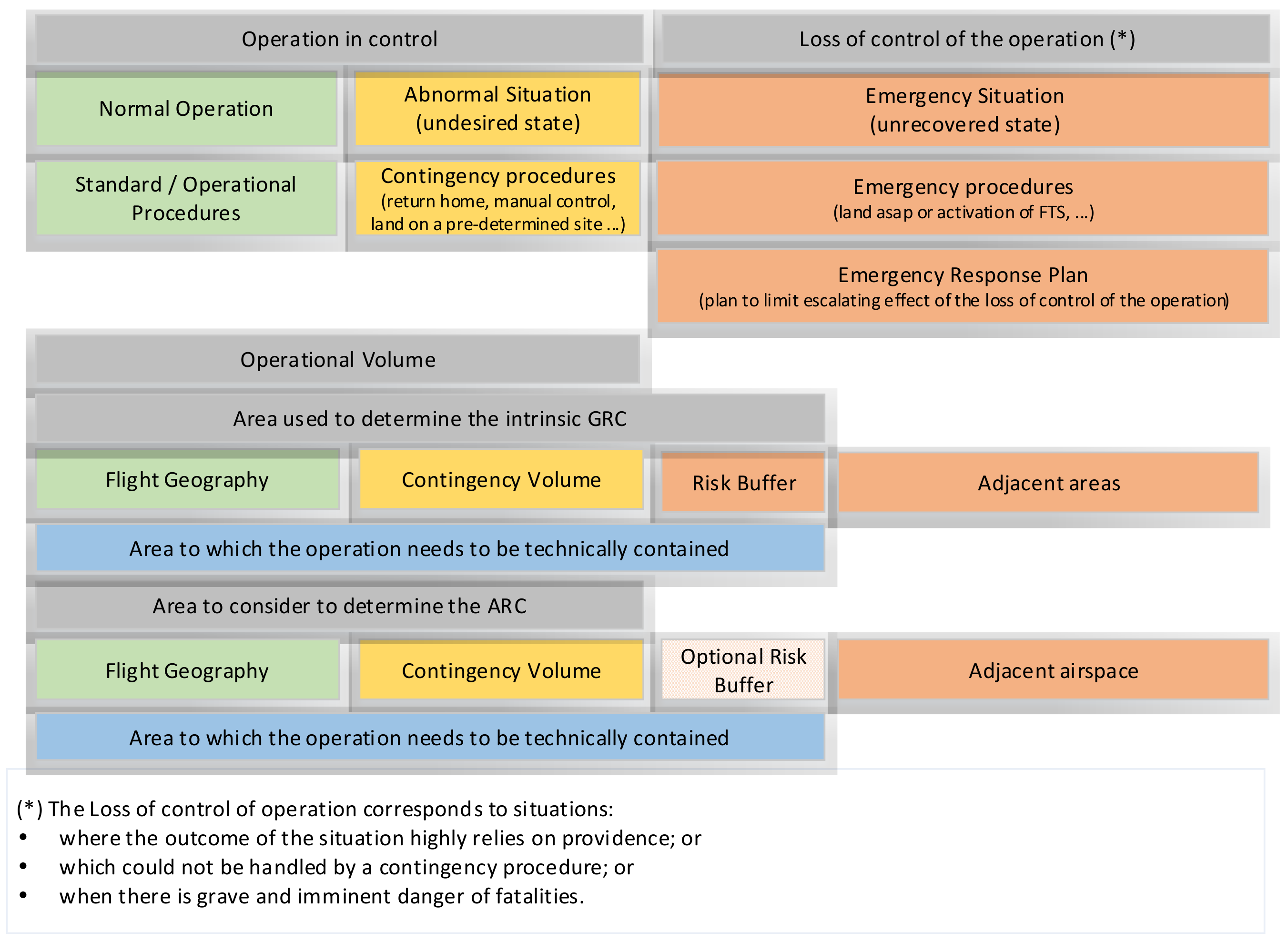
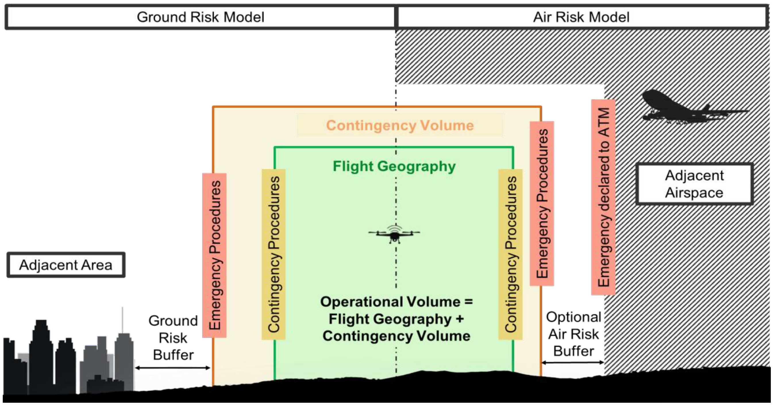
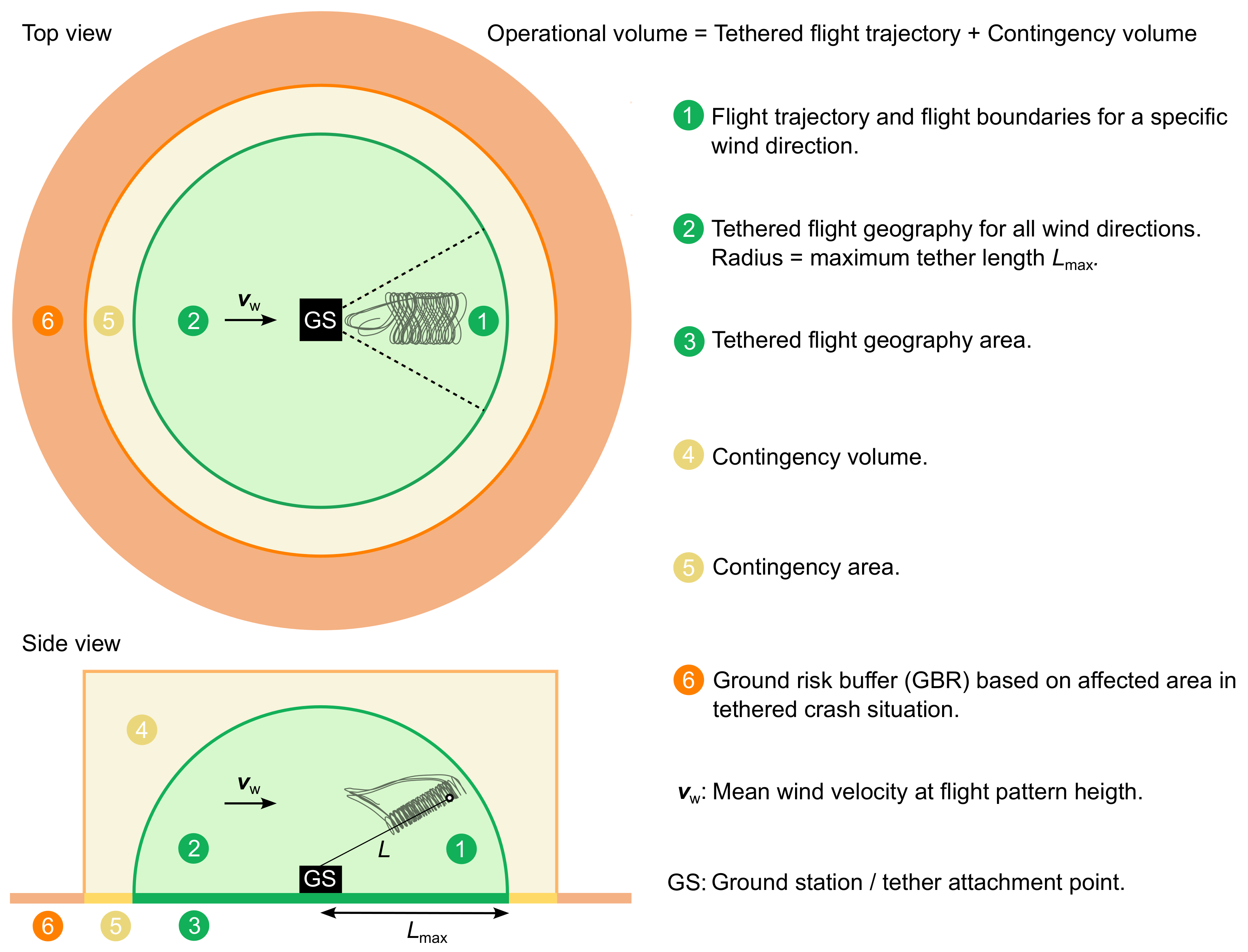
The SORA recommends standardizing the terminology for the phases of operation, the procedures, and the operational volumes, using the semantic models and definitions illustrated in Figure 1 and Figure 2. The Airborne Wind Europe safety working group has extended the original SORA semantic model to represent AWES’ operational space better. The new model is illustrated in Figure 3 with additional definitions in [26]. The maximum flight altitude is constrained by the maximum tether length, but can be further limited by geo-fencing using autopilot settings [27].
The terminology proposed in these figures is used in the present study as it can cover commercial AWES operations. Table 1 lists the individual SORA steps, which are grouped into sub-processes.
The present study executes the listed steps for a hypothetical AWE operation scenario with a hypothetical commercial AWES defined in Section 4 (SORA step 1).
3. Risk Introduction
To be consistent with the SORA, only the risk categories that cause the following harms are in the scope of the assessment:
- Fatal injuries to third parties on the ground.
- Fatal injuries to third parties in the air.
- Damage to critical infrastructure.
For the defined commercial operation scenario, the energy level of the airborne component is significantly higher than the amount of energy needed to cause fatal injuries in the case of a direct hit. Therefore, all crash cases are assumed to be potentially fatal. This work will quantify the fatal accident rate and other harms based on the operation hours (e.g., the fatal accident rate per million flying hours).
4. Sora Step 1: Conops Description
The starting point for the SORA is a “Concept of Operation” (CONOPS) document describing the system, defining the operation concept, and providing the operator’s safety culture. The document defines a hypothetical future commercial AWES and operation scenario representative of the state of research and development today. Even though each system implementation has its specific operation characteristics, we kept the safety considerations generally applicable. The main target of the discussion is establishing the lowest SAIL level. The main characteristics of the proposed system are the following:
- The airborne component is a single-unit flexible-wing kite with an area of 60 m2.
- Mechanical energy is transferred to the ground via the tether.
- The airborne component can land and take off without any human intervention.
- The flight controller design is robust to weather conditions such as strong wind, heavy rain, or snow. These conditions are considered abnormal operating conditions. Automatic procedures are in place in the flight control system, bringing it to a safe state if the operation is unsafe or not feasible. Undesirable states are not considered an anomaly, but a part of an operation where the system is still under control.
The operations concept of the system has the following main characteristics:
- The operation of the system is entirely autonomous. No ground intervention is required for the operation. There is no pilot or remote crew in the loop. Human intervention may be required only for maintenance purposes or emergency situations.
- The operation is continuous, both during the daytime and the nighttime.
- Airborne component visibility cannot be guaranteed from the ground station due to the weather and light conditions.
- Operations are conducted on a controlled ground area. Thus, only active participants, who have the training for the operation-relevant risks and emergency procedures, may be present in the defined area.
- The maximum allowed wind speed for the operation is 30 m/s, measured at ground level. For higher wind speeds, operations are terminated by the flight control system to protect the system and third parties.
- Operations are conducted with a single system.
- The operation volume is always free of local events and special circumstances.
- Adjacent areas of the operation area are classified as sparsely populated.
Some features of the system and operation definitions that may affect the risk assessment are left open for further discussion in the following steps. Thus, it will be possible to see the effect of the different design options on the risks assessment and, ultimately, on the SAIL level.
Annex A of the SORA [28] is intended to support the operators in collecting and presenting the operational information for the applicant system. This guideline is called the “Concept of Operations” (CONOPS) definition. The annex lists the following sections to be completed by the applicant:
- Operation relevant information
- (a)
- Organization
- Safety
- Design and production
- Training of staff involved in operations
- Maintenance
- Crew
- Configuration management
- (b)
- Operations
- Types of operations
- Standard operating procedures
- Normal operational strategy
- Abnormal and emergency operation
- Accidents, incidents, and mishaps
- Emergency response plan
- (c)
- Training
- General information
- Initial training and qualification
- Procedures for maintenance of currency
- Flight simulation training devices
- Training program
- Technical relevant information
- (a)
- UAS description
- Unmanned aircraft (UA) segment
- UAS control segment
- Geo fencing
- Ground support equipment (GSE) segment
- C2 link segment
- C2 link degradation
- C2 link lost
- Safety features
Human-controlled or human-supervised operation is not economically feasible for the ultimate commercial AWES. Therefore, emergency training, ground support equipment, ground control operators, and the command-and-control link are irrelevant to the commercial AWES certification.
For the SORA Step 1, it is assumed that the applicant fills CONOPS with the considerations presented. The first step is also to consider the organization’s safety culture. For our example case, the following assumptions are in place and to be documented by the AWE operator.
- A safety management system is in place and is documented.
- The organization uses “industry best practices” to design and produce its AWES.
- The organization has training procedures in place, and they are documented.
- The organization has maintenance procedures in place, and they are documented.
- The organization has a description of the responsibilities and duties of personnel involved in test operations, and it is documented.
- The organization has a change management system (CMS) defined, and it is documented.
- Normal operations consist of an airborne system connected to a ground station with a tether.
- The operator has documented their standard operating procedures, and they are appropriate for the operations being carried out.
- The operator has documented their normal operating strategy, and it is appropriate for the operations being carried out.
- The operator has documented their contingency procedures to be implemented in case of a system malfunction, abnormal operation, or an emergency situation. The critical failure modes of the system for all flight modes (i.e., launch, power production, land, etc.) have been analyzed by means of a failure mode and effects analysis (FMEA). At a minimum, this should include tether failure, ground station failure, and airborne system failure. An emergency landing procedure should be defined and documented. The tether release procedure should include provisions to ensure that the airborne part of the system does not leave the operational zone and that it results in an overall increase in safety and/or gives the operator a chance to minimize damage to their airborne system.
- The operator has an incident reporting procedure documented and known to all operation personnel. As a minimum, it is expected that any event involving the airborne system leaving the operational zone be reported to the local police and the certification authority.
- The operator has an emergency response plan in place that is documented and known to all operation personnel. As a minimum, the following scenarios should be covered: crash inside the operational zone, landing/crash outside of the operational zone, and collision with a manned aircraft.
- Descriptions of the physical characteristics of the airborne system (mass, center of mass, dimensions, etc.) including photos, diagrams, and schematics; the materials used; the capability of the airborne system to withstand expected flight loads; the dimensions of the tether; the airborne system performance characteristics (i.e., maximum altitude, endurance, accelerations, air-speeds, maximum ground speed, etc.); performance limits due to environmental and meteorological conditions (i.e., wind speed limitations, harsh weather conditions, minimum visibility conditions, temperatures limits, etc.); and the propulsion system, on-board power generation, flight control surfaces and actuators, sensors, and payloads (if applicable) have been documented and provided.
- Descriptions of the overall system architecture, navigation concept, autopilot, flight control system, and detect and avoid (DAA) system (if applicable) have been documented and provided.
- A description of the principles of the system or equipment used to perform geo-fencing functions has been provided. All AWES are connected to the ground by their tether. However, the tether cannot be claimed for the "geo-fence" requirement considering the energy level of the AWES during the operation. The developer should have a documentation system by which they can ensure that the airborne part of the system stays within the operational zone even in the tether rapture or release case.
- Descriptions of all the support equipment used on the ground, such as launch or recovery systems, generators, or power supplies; and how the AWES is transported on the ground have been provided.
- A description of the highly autonomous nature of the system is provided. Therefore, the inapplicability of the C2 link should be documented.
- Descriptions of the single failure modes of the system and their recovery modes have been provided, along with a description of the emergency recovery capability to prevent third-party risks (i.e., flight termination system or automatic recovery system). A functional and physical diagram of the overall system needs to be provided.
5. Sora Step 2: Determination of the Intrinsic UAS Ground Risk Class(Grc)
This step relates to the risk of a person being struck by the airborne component. This risk highly depends on the characteristics of the AWES. For example, the wingspan of a fixed-wing and a flexible-wing kite should be considered differently. The following operational constraints are assumed for the GRC determination:
- The airborne component consists of a 60 m2 flexible-wing kite and a suspended kite control unit (KCU),
- The operation is over a controlled ground area,
- The operation is at a maximum altitude of 600 m. Therefore, a ground risk buffer of 600 m is assumed.
The maximum UA characteristic of the kite is (such as the wingspan for fixed-wing or maximum dimension for multi-copters) the maximum length of the kite. For a 60 m2 kite, it is assumed that the maximum length is more than eight meters. The operation scenario is VLOS (Visual Line of Sight) or BVLOS (Beyond Visual Line of Sight) over a controlled area, as mentioned in the definition of the operation. Therefore, the resulting initial risk class is defined as “GRC:4” according to Table 2. For a typical free-fall case, the drag coefficient of the kite wing does not let the kite have significant kinetic energy. However, the kite can have higher kinetic energy levels if the control unit loses control when flying in strong wind conditions.
6. Sora Step 3: Final Grc Determination
In the final GRC determination step, applicants should offer mitigations to reduce the risk of a person being struck by the airborne component for a “loss of control” case. According to the SORA v.2, Table 3 is used to modify the calculated GRC. A negative number in the table denotes the decrease of GRC, while a positive number means a risk increment.
M1: Strategic mitigations are used to reduce the number of people at risk. Since selecting a controlled area already has the lowest risk value, further M1 mitigation is not applicable.
M3: ERP mitigation does not apply to commercial kite operations. Since many systems deployed in rural areas function autonomously, the operation and maintenance crew cannot respond to an incident on short notice. Therefore, M3 increases the GRC factor by one.
M2: This mitigation category aims to reduce the energy absorbed by people on the ground upon impact. These mitigations can be applied by reducing the UA impact dynamics (i.e., area, energy, impulse, transfer energy). One example of the M2 category is using an emergency parachute.
For a flexible-wing kite system, M2 category mitigations are considered technically feasible. Furthermore, M2 is the only mitigation category possible for the commercial operation case to reduce the ground risk. A safety system for ground (SSG), which detects the loss of control of the kite and reduces the kinetic energy of the kite immediately, can provide a reduction of GRC by a factor of two. The proposed SSG also reduces the risk of critical infrastructure harm, which the SORA does not cover. Therefore, such a system is considered a necessity for commercial AWES.
The SORA determines the robustness level considering each mitigation’s “level of integrity” and the claimed safety gain with a “level of assurance”. Table 4 guides the “level of assurance” value selection according to the criteria.
Table 5 presents the outcome “Level of robustness” according to the provided “Level of assurance” and “Level of integrity” values. The JARUS guidelines on SORA-Annex B [29] provide the Table 6 and Table 7 to assess the integrity and assurance levels of M2 mitigations.
To have the “High robustness” level for the SSG, both the “Level of integrity” and the “Level of assurance” values have to be “High”. Therefore, for a SSG that has a “High robustness level”, the following requirements have to be met according to Table 6 and Table 7:
- The activation of the SSG is automated.
- The effects of impact dynamics and post-impact hazards are reduced to a level where it can be reasonably assumed that a fatality will not occur.
- SSGs used to reduce the effect of the UA impact dynamics are installed and maintained under manufacturer instructions.
- The personnel responsible for the installation and maintenance of the SSG to reduce the effect of the UA impact dynamics are identified and trained by the applicant. A competent third party validates the claimed level of integrity against a standard considered adequate by the competent authority and through compliance acceptable to that authority.
Even though applicable standards are not clear yet in the SORA for claiming technical compliance, it is reasonable to assume that the civil aviation development standards will apply to the SSG development.
Assuming that a defined SSG system is in place, GRC for the defined commercial AWES operation is reduced by two points and defined as “GRC:2”.
7. Sora Step 4: Determination of the Initial Air Risk Class (Arc)
As with the ground risk determination process, the SORA determines the ARC by evaluating the inherent risk of a mid-air collision. After determining the initial air risk class, tactical and strategic mitigations may be proposed to decrease the ARC risk category. Operating during certain times or within certain boundaries may be an example of strategic mitigations. Tactical mitigations can be some form of detect-and-avoid systems or operational procedures.
The initial air risk class is directly derived from the maps of the airspace characterization studies by the competent authority. The applicant should use the dynamic or static air collision risk maps provided by the competent authority, air navigation service provider (ANSP), or UTM/U-Space service providers. The following factors affect the initial ARC determination:
- Operation altitude,
- Operating in controlled airspace or uncontrolled airspace,
- Operating in an environment that has an airport or heliport,
- Operating in airspace over urban or rural environment,
- Operating in typical airspace or atypical (e.g., segregated) airspace.
The SORA refers to UTM/U-Space to limit the risk of UAS encountering a crewed aircraft. Since UTM/U-Space is still in the early stages of development, the SORA has used the TM/U-Space mitigations to a limited extent [30].
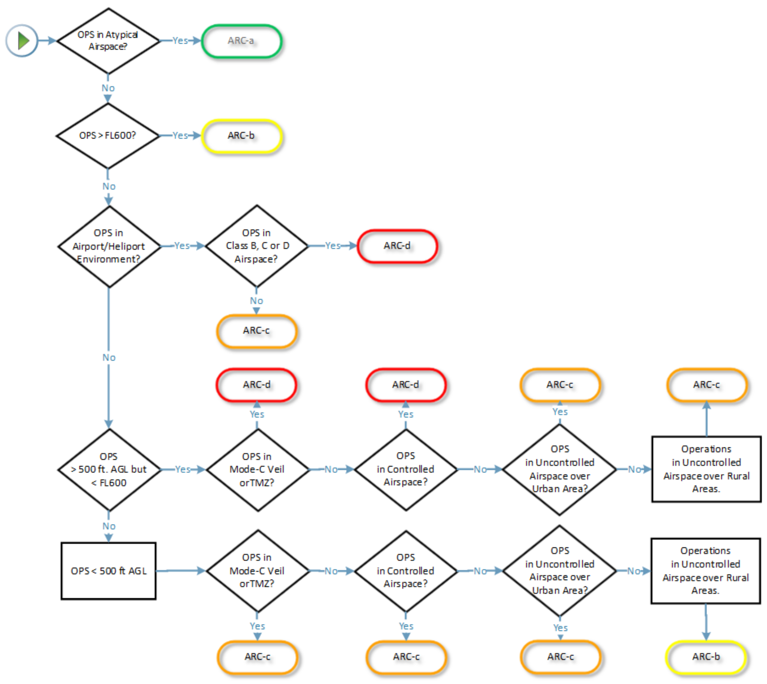
The SORA proposes the decision tree illustrated in Figure 4 to determine the initial ARC, where ARC-A represents the lowest risk category, and ARC-D represents the highest risk category.
In this decision tree, “atypical airspace” is defined as [31]:
- Restricted airspace or danger areas,
- Airspace where normal manned aircraft cannot go (e.g., airspace within 100 ft of buildings or structures),
- Airspace characterization where the encounter rate of manned aircraft (encounter is defined as a proximity of 3000 ft horizontally and ± 350 ft vertically) can be shown to be less than 1 × 10 per flight hour during the operation),
- Airspace not covered in Airspace Encounter Categories (AEC) 1 through 12.
The defined commercial AWES will not operate in “atypical airspace”.
The flight level (FL) is an aircraft’s altitude at the standard air pressure in aviation and aviation meteorology, expressed in hundreds of feet. Flight levels are usually designated in writing as FLxxx, where xxx is a two- or three-digit number indicating the pressure altitude in units of 100 ft (30 m) [32]. FL600 means the top of class A airspace corresponding to a 60,000 ft pressure altitude, the approximate top of the troposphere. This altitude is above commercial airliner operations. This condition is not the case for representative commercial AWE operations.
Operations of the first commercial AWES are assumed to be conducted in uncontrolled airspace where an air traffic control (ATC) service is not deemed necessary or cannot be provided for practical reasons. More specifically, operations are expected to be in airspace class G, where the ATC has no authority for the separation. For the future of AWES, operations may be located in special airspace, which limits the pilot operation in certain areas. Currently, special airspace consists of prohibited areas, restricted areas, warning areas, military operation areas (MOAs), alert areas, and controlled firing areas (CFAs), all of which are not on the flight charts.
Being in uncontrolled airspace class G does not exclude nearby airports and heliports. Therefore, it is required to ensure that there is no airport or heliport in the vicinity of the operation area or that the operations are coordinated.
“Mode C veil” refers to a kind of airspace that currently surrounds all primary Class B airports. This airspace extends horizontally in a circle of 30 NM radius centered on the airport and extends vertically from the surface up to 10,000 ft MSL (mean sea level) [33]. The name refers to the mode of transponder operation required within this airspace—that is, with minimal exceptions, all aircraft operating within this airspace must have an altitude-reporting Mode C transponder in operation. The “Mode C veil” is unnecessary for the commercial AWES operation.
A transponder mandatory zone (TMZ) is an airspace of defined dimensions wherein the carriage and operation of transponder equipment is mandatory. It is not expected to operate in TMZ for the assumed commercial AWES.
The operation altitude of the assumed system will be higher than 500 ft, but less than FL600 level, which means 60,000 ft above mean sea level when the pressure at sea level is 1.013 bar.
From the air risk category (ARC) point of view, there is no difference between operating over rural and urban areas. Nevertheless, this has a significant impact on GRC. Therefore, the recommendation for the first AWES commercial scenario is to operate over controlled ground areas only.
By executing the SORA decision tree for the initial ARC determination with the inputs from the representative operation scenario above, the initial air risk category for the commercial AWES is ARC-C. This qualitative category represents the rate the AWE would encounter with a crewed aircraft. The actual air collision risk can be mitigated further with tactical and strategic mitigations.
The SORA states that the competent authority may raise the operation volume ARC to a higher level considering the circumstances, which could invalidate the decisions taken in Figure 4.
Therefore, to agree with the competent authority on the same initial ARC, it is the applicant’s responsibility to ensure the decisions on the decision tree are always valid, even in undesired operational events such as losing control. Therefore, we will enhance the SSG requirements proposed in-ground risk assessment steps to cover the ARC-related requirements. Thus, SSG will be used to keep the operational envelope requirements used in the initial ARC determination.
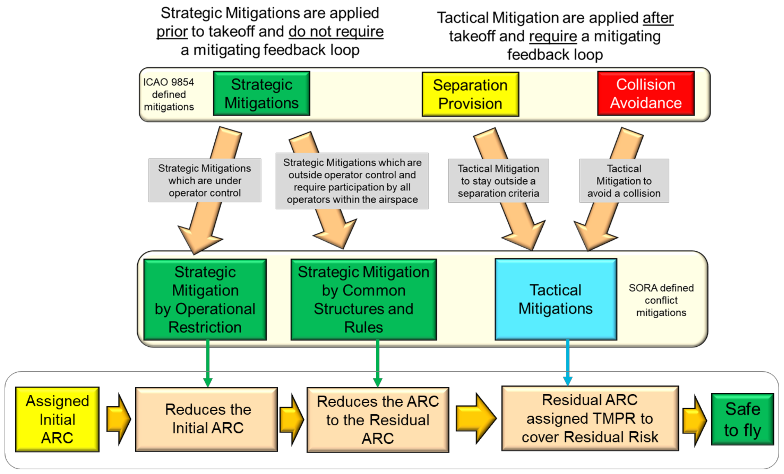
Figure 5 shows the SORA’s approach for the mitigations to reduce the determined initial ARC.
8. Sora Step 5: Application of Strategic Mitigations to Determine Residual Arc (Optional)
According to [30], the most common strategic mitigations by operational restriction are:
- Mitigation(s) that bound the geographical volume in which the UAS operates (e.g., certain boundaries or airspace volumes);
- Mitigation(s) that bound the operational time frame (e.g., restricted to certain times of day, such as flying only at night).
A restriction on the timeframe is not a commercially feasible strategic mitigation for AWES operations.
The mentioned geographic volume restriction here is for claiming a lower ARC despite the high encounter risk. For example, an UAS operation in Class B airspace has a high rate of encountering a crewed aircraft. However, the UAS system can operate at the outer reaches of the Class B airspace where crewed aircraft do not routinely fly and can claim ARC reduction for its operation volume.
The selected operation volume for the representative commercial AWE is already the safest option (Class G, uncontrolled airspace, not being close to airports and heliports) where the AWE operation is still feasible. Therefore, no additional strategic mitigation applies to this step.
9. Sora Step 6: Tactical Mitigations Performance Requirement (TMPR) and Robustness Levels
VLOS stands for visual line of sight, meaning that the UAS during the entire flight must be clearly visible by the UAS operator. VLOS operation for commercial AWES is not possible when considering 24/7 operation under various weather conditions at the operation altitudes of AWES. In addition to the operation conditions, a continuous “pilot in control” is not feasible for commercial AWES. Therefore, the “see and avoid” maneuver is not a tactical mitigation for the commercial AWES.
However, to further reduce the ARC of commercial AWES, DAA systems for triggering a passive separation maneuver (e.g., activating an emergency landing) may be a feasible tactical mitigation factor. According to Table 8, the TMPR level for an “ARC-C” system should be at least “Medium”.
The “Medium TMPR requirement” is explained in the SORA as follows:
“A medium TMPR will be required for operations in airspace where the chance of encountering manned aircraft is reasonable, and/or the strategic mitigations available are medium. Operations with a medium TMPR will likely be supported by the systems currently used in aviation to aid the remote pilot in the detection of other manned aircraft or by systems designed to support aviation that are built to a corresponding level of robustness. Traffic avoidance maneuvers could be more advanced than for a low TMPR.”
As stated in the explanation, SORA assumes a “pilot in control” for medium TMPR. The second point, which is open to interpretation, is the possibility of required advanced traffic avoidance maneuvers. For the lower TMPRs (e.g., operations below 500 ft), an example of an expected maneuver is rapid descent to an altitude where crewed aircraft do not operate. These points remain open for commercial AWES, and the expected automatic traffic avoidance maneuver needs to be agreed upon with the competent authority. A quantitative risk assessment or simulation with results to justify the low risk of a crash with the emergency landing maneuver may be necessary even under the rare occurrence of sharing the same airspace with the crewed aircraft. Note that the GRC for commercial AWES was calculated as 2 in the GRC determination steps.
Table 9 shows that a reduction in the ARC level from C to B significantly affects the resulting SAIL category for an ARC-3 UAS system. Therefore, a DAA system and a separation maneuver designed for emergency separation when encountering a crewed aircraft may be necessary for commercial AWES. The required separation maneuver is specific to different AWES, and, therefore, the design of the maneuver is not in the scope of this work. However, the main characteristics of DAA systems currently on the market will be discussed.
A DAA system should observe the environment surrounding the AWES to decide whether a collision is imminent. DAA systems are not only for detecting and avoiding other aircraft, but also for being seen so the other aircraft or UAS can detect and avoid them. Companies started to offer DAA systems for drones after advancements in drone airworthiness requirements. Similar systems can be used for AWES. However, a DAA system that is particularly used in AWES should also consider the case of crashing into the tether and plan the avoidance maneuver considering the tether. DAA systems would work both for cooperative and non-cooperative aerial vehicles. Considering the operation altitudes and the commercial operation scenario of AWES, the probability of encountering a non-cooperative aircraft is higher than cooperative aircraft. The sensors in the DAA systems can be categorized into two classes: passive and active. Radar, Lidar, or ultrasonic sensors are active sensors that emit and use the reflected signal for detection. Passive sensors use the signal emitted by the target. For example, IR (infrared) and visual cameras are passive sensors. An example system with cameras utilizes a computer-vision system using artificial intelligence methods to mimic the pilots’ perception to replace “see and avoid” in traditional aviation [34]. These systems consume less electric power and are light-weighted, which makes them good candidates for integrating the airborne component of an AWES. However, their estimation of obstacle distances is less accurate, and their detection performance may be affected by weather conditions.
Systems with active sensors provide more accurate distance measurement as they use time-of-flight data of the signal. However, these systems are heavier and require more electric power, making them unsuitable for integration into the airborne component of AWES. However, active sensors may integrate into the ground component of AWES, considering that the airborne component is always near the ground station. Then, the calculated position of the airborne component can be fed into the system on the ground for the correct calculation of the crash probability and avoidance maneuver. Even though this approach requires modification on the available DAA system, which may require re-qualification, it is considered the most feasible way for the long term.
10. Sora Step 7: Final Specific Assurance and Integrity Levels (SAIL) and Operational Safety Objectives (OSO) Assignment
SORA step 7 aims to consolidate the determined GRC and ARC to acquire the SAIL parameter, representing the confidence level that the AWE operation will stay under control. Table 9 shows how the final SAIL is determined using GRC and ARC inputs.
Considering the discussion and CONOPS assumptions taken, the consolidated SAIL parameter for commercial AWES is “SAIL: II”, with the calculated “GRC:2” an “ARC-B”.
11. Sora Step 8: Identification of Operational Safety Objectives (OSO)
SORA step 8 gives the expected levels for safety objectives according to the SAIL number in three qualitative categories. These are Low (L), Medium (M), and High (H). If a safety objective is not mandatory for the given SAIL, it is marked as Optional (O) to leave it as recommended. The operators’ responsibility is to provide evidence that indicates the objectives are satisfied with the associated level of robustness.
For the SAIL: II category, the highest expected robustness level for the safety objectives is “Medium”. Namely, for SAIL: II, there is no operational safety objective whose robustness level has to be “High”. Table 10, Table 11, Table 12 and Table 13 list the required objectives for SAIL: II, which is the determined SAIL category for the representative commercial AWES. These lists should be considered the minimum set that was asked historically for the safety of the UAS operations. The competent authority may extend the list or change the associated robustness levels.
This list of OSOs developed for the systems has the “pilot in control” and has a “remote crew on the field” Therefore, in the last column of the tables, the OSOs’ applicability for the commercial AWES has been assessed.
12. Sora Step 9: Adjacent Area/Airspace Considerations
In the previous steps, the GRC and ARC determined a well-defined operation scenario on a strictly defined ground area and airspace volume. SORA step 9 addresses the risk of UAS control loss and, consequently, the infringement of the adjacent airspace or ground areas. The requirement for the operation containment is the following:
“No probable failure of the UAS or any external system supporting the operation shall lead to operation outside of the operational volume. Compliance with the requirement above shall be substantiated by a design and installation appraisal and shall minimally include: - design and installation features (independence, separation, and redundancy); - any relevant particular risk (e.g., hail, ice, snow, electro-magnetic interference) associated with the CONOPS”
The term “Probable” in the requirement means “Anticipated to occur one or more times during the entire system/operational life of an item” [20].
The flight control system keeps the airborne component in the operation volume. The flight control system receives the inputs such as position, wind speed, and tether tension from various subsystems. All these inputs are critical for keeping the system in operation volume. To meet the requirement of the SORA, there are two possible approaches:
- Developing and qualifying the entire flight control system and all flight-relevant subsystems with a credible development standard.
- Developing and qualifying an independent system that always keeps the airborne component in the operation zone in a failure case.
Considering the technology maturity level and ongoing improvement of current AWES flight control systems (and subsystems), the second option considered more reasonable for the time being is to keep the technology development going. Qualifying an entire system costs significantly more than qualifying a system with a dedicated task. Therefore, this study derives the following high-level requirements of an independent system that ensures that the airborne component is always in the operation zone:
- The fault detection system shall detect the position-keeping failure of the flight control system using independent algorithms/sensors.
- All critical hardware, sensors, and software should meet the reliability metric requirements, or redundancy should ensure reliability. The hardware and the software of the system shall be qualified with a credible standard.
- If position control is lost, the system shall have the mechanism to conduct a controlled landing or crash in the operation zone. The component of this emergency system should have the same quality level as the detection module.
SORA Step 9 requires meeting the following requirements:
- The probability of leaving the operational volume per flight hour shall be less than .
- No single failure of the UAS or any external system supporting the operation shall lead to operation outside the ground risk buffer. Compliance with the requirements above shall be substantiated by analysis or test data with supporting evidence.
- Software (SW) and Airborne Electronic Hardware (AEH) whose development error(s) could directly lead to operations outside of the ground risk buffer shall be developed to an industry standard or methodology recognized as adequate by the competent authority.
However, these safety requirements are only applicable if the adjacent operation areas are:
- Gatherings of people unless already approved for operations over gatherings of people;
- ARC-D unless the residual ARC is ARC-D;
or in populated environments where:
- M1 mitigation has been applied to lower the GRC;
- Operating in a controlled ground area.
Because none of these adjacent conditions are met for the defined operational scenario of commercial AWES, we conclude that the requirements are not applicable.
13. Sora Step 10: Comprehensive Safety Portfolio
SORA Step 10 summarizes the following objectives and mitigations:
- Mitigations used to modify the intrinsic GRC;
- Strategic mitigations for the initial ARC;
- Tactical mitigations for the residual ARC;
- Adjacent area/airspace considerations;
- Operational safety objectives.
Proper implementation of these claimed mitigations and satisfactory evidence are needed for a sufficient confidence level in the system. The operator should address additional requirements such as security and environmental requirements. The activities for the SORA may address some of these additional requirements, but the operator should ensure covering them all. Then, the operator is responsible for ensuring the consistency between the documented SORA safety case and the actual operational conditions.
14. Conclusions
The airborne wind energy (AWE) sector has grown steadily in the last decade, and the technology is increasingly attracting the attention of governments, policymakers, and industry. The current main barrier to commercialization is reaching the reliability and safety levels required for long-term operation in relevant wind environments. Because of the flying energy-harvesting devices, airborne wind energy systems (AWES) are closer to highly autonomous vehicles, drones, and robots than to wind turbines. Despite the many prototypes today, there has yet to be an agreed upon way forward for the commercial operation approval of AWES.
For a decade, much effort was invested in integrating unmanned aerial systems (UAS) safely into airspace. The European Union Aviation Safety Agency (EASA) has created a regulation for the flight approval of UAS with three categories. One of the categories, denoted “specific”, is for non-regular UAS, which need to be investigated independently to make an ad hoc risk assessment. Commercial AWES fit well into this category. The Joint Authorities for Rulemaking on Unmanned Systems (JARUS) worked on a framework to guide the risk assessment process of specific UAS. This framework is called specific operations risk assessment (SORA), which we consider the most advanced framework as a starting point for commercial AWES operation approval. In this paper, we execute the SORA process for a hypothetical commercial AWES operation case to define the specific assurance and integrity level (SAIL) category of commercial AWES. We reduced the initial ground risk class (GRC) from “GRC:4” to “GRC:2” by proposing a safety system for ground (SSG) that detects the airborne component’s control loss case and immediately reduces the kinetic energy of the kite. This system also reduces the risk of critical infrastructure harm, which the SORA does not cover. The initial air risk class (ARC) is determined as “ARC-C” for the assumed commercial operation. This category defines the probability of encountering an aircraft during the operation. We have proposed a tactical mitigation, which requires a detect and avoid (DAA) system and a separation maneuver designed for the emergency separation to reduce the ARC further to “ARC-B”.
With the proposed GRC and ARC mitigations, the consolidated SAIL, the level of confidence that the UAS operation will stay under control, is increased by a factor of two and determined as “SAIL: II”. The proposed mitigations significantly improved the safety levels of commercial operations. We think that applying the proposed mitigations in this paper will increase AWES’s safety level, ultimately leading to operation approval.
Author Contributions
Conceptualization, V.S. and R.S.; methodology, V.S.; writing—original draft preparation, V.S.; writing—review and editing, R.S.; supervision, R.S. All authors have read and agreed to the published version of the manuscript.
Funding
This research received no external funding.
Data Availability Statement
Not applicable.
Acknowledgments
The authors would like to thank Corey Houle and Rolf Luchsinger, of TwingTec AG, and Johannes Peschel, of Kitepower B.V., for providing feedback on the draft version of the manuscript.
Conflicts of Interest
The authors declare no conflict of interest.
Abbreviations
The following abbreviations are used in this manuscript:
| AEC | Airspace encounter categories |
| AEH | Airborne electronic hardware |
| ANSP | Air navigation service provider |
| ARC | Air risk class |
| ATC | Air traffic control |
| AWE | Airborne wind energy |
| AWES | Airborne wind energy system |
| BVLOS | Beyond visual line of sight |
| C2 | Command and control |
| CFA | Controlled firing area |
| cFS | Core flight system |
| CMS | Change management system |
| CONOPS | Concept of operations |
| DAA | Detect and avoid |
| EASA | European Union Aviation Safety Agency |
| ESA | European Space Agency |
| FDIR | Fault detection and isolation |
| FL | Flight level |
| FMEA | Failure mode and effects analysis |
| GRC | Ground risk class |
| GSE | Ground support equipment |
| HAV | Highly autonomous vehicles |
| IR | Infrared |
| JARUS | Joint Authorities for Rulemaking on Unmanned Systems |
| KCU | Kite control unit |
| LEO | Low-earth-orbit |
| LOS | Line of sight |
| MSL | Mean sea level |
| MOA | Military operation area |
| NASA | National Aeronautics and Space Administration |
| OSO | Operational safety objective |
| RPAS | Remote-piloted aircraft system |
| SAE | Society of Automotive Engineers |
| SAIL | Specific assurance and integrity level |
| SAVOIR | Space avionics open interface architecture |
| SORA | Specific operations risk assessment |
| SSG | Safety system for ground |
| SW | Software |
| TMPR | Tactical mitigation performance and robustness requirements |
| TMZ | Transponder mandatory zone |
| TRL | Technology readiness level |
| UA | Unmanned aircraft |
| UAS | Unmanned aerial system |
| UTM | Unmanned aircraft system traffic management |
| VLOS | Visual line of sight |
References
- Zillmann, U.; Bechtle, P. Emergence and Economic Dimension of Airborne Wind Energy. In Airborne Wind Energy—Advances in Technology Development and Research; Schmehl, R., Ed.; Springer Nature: Singapore, 2018; pp. 1–25. [Google Scholar] [CrossRef]
- IRENA. Offshore Renewables: An Action Agenda for Deployment; Technical Report; International Renewable Energy Agency (IRENA): Abu Dhabi, United Arab Emirates, 2021. [Google Scholar]
- Vermillion, C.; Cobb, M.; Fagiano, L.; Leuthold, R.; Diehl, M.; Smith, R.S.; Wood, T.A.; Rapp, S.; Schmehl, R.; Olinger, D.; et al. Electricity in the Air: Insights From Two Decades of Advanced Control Research and Experimental Flight Testing of Airborne Wind Energy Systems. Annu. Rev. Control 2021, 52, 330–357. [Google Scholar] [CrossRef]
- Fagiano, L.; Quack, M.; Bauer, F.; Carnel, L.; Oland, E. Autonomous Airborne Wind Energy Systems: Accomplishments and Challenges. Annu. Rev. Control Robot. Auton. Syst. 2022, 5, 603–631. [Google Scholar] [CrossRef]
- Rapp, S.; Schmehl, R. Enhancing Resilience of Airborne Wind Energy Systems Through Upset Condition Avoidance. J. Guid. Control Dyn. 2021, 44, 251–265. [Google Scholar] [CrossRef]
- Salma, V.; Friedl, F.; Schmehl, R. Improving Reliability and Safety of Airborne Wind Energy Systems. Wind Energy 2019, 23, 340–356. [Google Scholar] [CrossRef] [Green Version]
- Minderhoud, C. Safety Evaluation of Kitepower Operations. Master’s Thesis, Delft University of Technology, Delft, The Netherlands, 2021. [Google Scholar]
- Schmidt, H.; de Vries, G.; Renes, R.J.; Schmehl, R. The Social Acceptance of Airborne Wind Energy: A Literature Review. Energies 2022, 15, 1384. [Google Scholar] [CrossRef]
- Watson, S.; Moro, A.; Reis, V.; Baniotopoulos, C.; Barth, S.; Bartoli, G.; Bauer, F.; Boelman, E.; Bosse, D.; Cherubini, A.; et al. Future emerging technologies in the wind power sector: A European perspective. Renew. Sustain. Energy Rev. 2019, 113, 109270. [Google Scholar] [CrossRef]
- Koopman, P.; Ferrell, U.; Fratrik, F.; Wagner, M. A Safety Standard Approach for Fully Autonomous Vehicles. In Proceedings of the Computer Safety, Reliability, and Security; Romanovsky, A., Troubitsyna, E., Gashi, I., Schoitsch, E., Bitsch, F., Eds.; Springer: Cham, Switzerland, 2019; pp. 326–332. [Google Scholar] [CrossRef]
- Salma, V.; Ruiterkamp, R.; Kruijff, M.; van Paassen, M.; Schmehl, R. Current and Expected Airspace Regulations for Airborne Wind Energy Systems. In Airborne Wind Energy—Advances in Technology Development and Research; Schmehl, R., Ed.; Green Energy and Technology; Springer: Singapore, 2018; Chapter 29; pp. 703–725. [Google Scholar] [CrossRef] [Green Version]
- Eickhoff, J.; Chintalapati, B.; Stoecker, P.; von Kader, W.; Traussnig, R.; Sayer, C.; Peel, R.; Keynes, M. The Flexible LEO Platform for Small Satellite Missions; Deutsche Gesellschaft für Luft-und Raumfahrt-Lilienthal-Oberth e.V.: Friedrichshafen, Germany, 2018. [Google Scholar] [CrossRef]
- National Aeronautics and Space Administration (NASA). The Core Flight System (cFS). Available online: https://cfs.gsfc.nasa.gov (accessed on 12 August 2021).
- Salma, V.; Schmehl, R. Flight Anomaly Detection for Airborne Wind Energy Systems. J. Phys. Conf. Ser. 2020, 1618, 032021. [Google Scholar] [CrossRef]
- Olive, X. FDI (R) for satellites: How to deal with high availability and robustness in the space domain. Int. J. Appl. Math. Comput. Sci. 2012, 22, 99–107. [Google Scholar] [CrossRef] [Green Version]
- European Space Agency (ESA). SAVOIR-FDIR Working Group. Available online: https://savoir.estec.esa.int/SAVOIRFDIR.htm (accessed on 1 February 2021).
- National Aeronautics and Space Administration (NASA). Fault Management Handbook; Technical Report NASA-HDBK-1002; NASA: Washington, DC, USA, 2012. Available online: https://www.nasa.gov/pdf/636372main_NASA-HDBK-1002_Draft.pdf (accessed on 11 January 2023).
- Underwriters Laboratories Partners. ANSI/UL 4600 Standard for Safety for the Evaluation of Autonomous Products. Available online: https://www.shopulstandards.com/ProductDetail.aspx?productid=UL4600 (accessed on 11 January 2023).
- European Aviation Safety Agency (EASA). SC-RPAS.1309-01: Special Condition Equipment, Systems, and Installations. 24 July 2015. Available online: https://www.easa.europa.eu/system/files/dfu/SC-RPAS.1309-01_Iss01-public%20consultation.pdf (accessed on 15 March 2023).
- Joint Authorities for Rulemaking of Unmanned Systems (JARUS). JARUS Guidelines on Specific Operations Risk Assessment (SORA). Edition 2.0. 30 January 2019. Available online: http://jarus-rpas.org/sites/jarus-rpas.org/files/jar_doc_06_jarus_sora_v2.0.pdf (accessed on 31 January 2023).
- European Union Aviation Safety Agency (EASA). Specific Operations Risk Assessment (SORA). Available online: https://www.easa.europa.eu/en/domains/civil-drones-rpas/specific-category-civil-drones/specific-operations-risk-assessment-sora (accessed on 29 January 2023).
- Janik, P.; Zawistowski, M.; Fellner, R.; Zawistowski, G. Unmanned Aircraft Systems Risk Assessment Based on SORA for First Responders and Disaster Management. Appl. Sci. 2021, 11, 5364. [Google Scholar] [CrossRef]
- Airborne Wind Europe. Safe AWE Testing CONOPS Guidelines. Edition 1.1. 25 January 2021. [Google Scholar] [CrossRef]
- Airborne Wind Europe. An Introduction to the Specific Operations Risk Assessment (SORA) for Airborne Wind Energy. Edition 1.1. 25 January 2021. [Google Scholar] [CrossRef]
- Peschel, J. Kitepower and the Journey Towards 24/7 Operation. In 8th International Airborne Wind Energy Conference (AWEC 2019): Book of Abstracts; Schmehl, R., Tulloch, O., Eds.; University of Strathclyde: Glasgow, UK; Delft University of Technology: Delft, The Netherlands, 2019; Available online: http://resolver.tudelft.nl/uuid:5bea59d6-be63-46c6-aba5-d60967d7783b (accessed on 11 January 2023).
- Airborne Wind Europe. Glossary. Available online: https://airbornewindeurope.org/glossary-2/ (accessed on 11 January 2023).
- Torens, C.; Nikodem, F.; Dauer, J.C.; Schirmer, S.; Dittrich, J.S. Geofencing requirements for onboard safe operation monitoring. CEAS Aeronaut. J. 2020, 11, 767–779. [Google Scholar] [CrossRef]
- Joint Authorities for Rulemaking of Unmanned Systems (JARUS). JARUS Guidelines on SORA—Annex A, Guidelines on Collecting and Presenting System and Operation Information for a Specific UAS Operation. Edition 1.0. 26 June 2017. Available online: http://jarus-rpas.org/sites/jarus-rpas.org/files/jar_doc_06_jarus_sora_annex_a_v1.0.pdf (accessed on 16 August 2021).
- Joint Authorities for Rulemaking of Unmanned Systems (JARUS). JARUS Guidelines on SORA-Annex B, Integrity and Assurance Levels for the Mitigations Used to Reduce the Intrinsic Ground Risk Class. Edition 1.0. 25 January 2019. Available online: http://jarus-rpas.org/sites/jarus-rpas.org/files/jar_doc_06_jarus_sora_annex_b_v1.0.pdf (accessed on 16 August 2021).
- Joint Authorities for Rulemaking of Unmanned Systems (JARUS). JARUS Guidelines on SORA - Annex C, Strategic Mitigation Collision Risk Assessment. Edition 1.0. 30 January 2019. Available online: http://jarus-rpas.org/sites/jarus-rpas.org/files/jar_doc_06_jarus_sora_annex_c_v1.0.pdf (accessed on 16 August 2021).
- Joint Authorities for Rulemaking of Unmanned Systems (JARUS). JARUS Guidelines on SORA—Annex I, Glossary of Terms. Edition 1.0. 26 June 2017. Available online: http://jarus-rpas.org/sites/jarus-rpas.org/files/jar_doc_06_jarus_sora_annex_i_v1.0.pdf (accessed on 16 August 2021).
- Wikipedia. Flight Level. Available online: https://en.wikipedia.org/wiki/Flight_level (accessed on 16 August 2021).
- Wikipedia. Mode C Veil. Available online: https://en.wikipedia.org/wiki/Mode_C_veil (accessed on 16 August 2021).
- Iris Automation. Detect-and-Avoid Drone Collision Avoidance System, Iris Automation. Available online: https://www.unmannedsystemstechnology.com/company/iris-automation/ (accessed on 17 August 2021).
Figure 1.
SORA semantic model. Reprinted with permission from [20]. Copyright (2019) JARUS.
Figure 1.
SORA semantic model. Reprinted with permission from [20]. Copyright (2019) JARUS.

Figure 2.
Graphical representation of the SORA semantic model. Reprinted with permission from [20]. Copyright (2019) JARUS.
Figure 2.
Graphical representation of the SORA semantic model. Reprinted with permission from [20]. Copyright (2019) JARUS.

Figure 3.
Definition of the operational volume for AWES and related terminology. The ground risk buffer is calculated according to JARUS’ ground risk model with a significant safety factor.
Figure 3.
Definition of the operational volume for AWES and related terminology. The ground risk buffer is calculated according to JARUS’ ground risk model with a significant safety factor.

Figure 4.
ARC assignment process. Reprinted with permission from [20]. Copyright (2019) JARUS.
Figure 4.
ARC assignment process. Reprinted with permission from [20]. Copyright (2019) JARUS.

Figure 5.
SORA air-conflict mitigation process. Reprinted with permission from [30]. Copyright (2019) JARUS.
Figure 5.
SORA air-conflict mitigation process. Reprinted with permission from [30]. Copyright (2019) JARUS.


Table 1.
Subprocesses and steps in the SORA process, compiled from [20].
Table 1.
Subprocesses and steps in the SORA process, compiled from [20].
| Step 1 | CONOPS description |
| Ground risk process | |
| Step 2 | Determination of the intrinsic UAS ground risk class (GRC) |
| Step 3 | Final GRC determination |
| Air-risk process | |
| Step 4 | Determination of the initial air risk class (ARC) |
| Step 5 | Application of strategic mitigations to determine residual risk |
| Step 6 | Tactical mitigation performance requirement (TMPR) and robustness levels |
| Final specific assurance and integrity levels (SAIL) and operational safety objectives (OSO) assignment | |
| Step 7 | SAIL determination |
| Step 8 | Identification of operational safety objectives (OSO) |
| Step 9 | Adjacent area/airspace considerations |
| Step 10 | Comprehensive safety portfolio |
Table 2.
Determination of the intrinsic ground risk classes (GRC) [20].
Table 2.
Determination of the intrinsic ground risk classes (GRC) [20].
| Intrinsic UAS Ground Risk | ||||
|---|---|---|---|---|
| Max UAS characteristic dimension | 1 m | 3 m | 8 m | >8 m |
| Typical kinetic energy expected | <700 J | <34 KJ | <1084 KJ | >1084 KJ |
| Operational scenarios | ||||
| VLOS/BVLOS over controlled ground area | 1 | 2 | 3 | 4 |
| VLOS in sparsely populated environment | 2 | 3 | 4 | 5 |
| BVLOS in sparsely populated environment | 3 | 4 | 5 | 6 |
| VLOS in populated environment | 4 | 5 | 6 | 8 |
| BVLOS in populated environment | 5 | 6 | 8 | 10 |
| VLOS over gathering of people | 7 | |||
| BVLOS over gathering of people | 8 | |||
Table 3.
Mitigations for final GRC determination [20].
Table 3.
Mitigations for final GRC determination [20].
| Robustness | ||||
|---|---|---|---|---|
| Mitigation Sequence | Mitigations for Ground Risk | Low/None | Medium | High |
| 1 | M1 - Strategic mitigations for ground risk | 0: None −1: Low | −2 | −4 |
| 2 | M2 - Effects of ground impacts are reduced | 0 | −1 | −2 |
| 3 | M3 - An emergency response plan (ERP) is in place, operator validated, and effective | 1 | 0 | −1 |
Table 4.
Required criteria for integrity levels.
| Level of Integrity | Criteria Definition |
|---|---|
| Low | Only the applicants’ declaration, which states that the required level of integrity has been achieved, is applicable. |
| Medium | Where the applicant provides supporting evidence regarding the level of integrity. This is typically achieved by means of testing. |
| High | The achieved integrity has been found acceptable by a competent third party. |
Table 5.
Determination of robustness level [20].
Table 5.
Determination of robustness level [20].
| Low Assurance | Medium Assurance | High Assurance | |
|---|---|---|---|
| Low integrity | Low robustness | Low robustness | Low robustness |
| Medium integrity | Low robustness | Medium robustness | Medium robustness |
| High integrity | Low robustness | Medium robustness | High robustness |
Table 6.
Level of integrity assessment criteria for ground risk of non-tethered M1 mitigations [29].
Table 6.
Level of integrity assessment criteria for ground risk of non-tethered M1 mitigations [29].
| Level of Integrity | ||||
|---|---|---|---|---|
| Criterion Number | Low | Medium | High | |
| 1 | Definition of ground risk buffer | A ground risk buffer with at least a 1 to 1 rule. | Ground risk buffer takes into consideration: - 2 improbable single malfunctions or failures (including the projection of high energy parts such as rotors and propellers), which would lead to an operation outside of the operational volume, - Meteorological conditions (e.g., wind), - UAS latencies (e.g., latencies that affect the timely maneuverability of the UA), - UA behavior when activating a technical containment measure, - UA performance. | Same as Medium |
| 2 | Evaluation of people at risk | The applicant evaluates the area of operations by means of on-site inspections/appraisals to justify lowering the density of people at risk (e.g., residential area during daytime when some people may not be present or an industrial area at night time for the same reason). | Same as low; however, the applicant makes use of authoritative density data (e.g., data from UTM data service provider) relevant for the proposed area and time of operation to substantiate a lower density of people at risk. AND/OR If the applicant claims a reduction, due to a sheltered operational environment, the applicant: - uses a drone below 25 kg and not flying above 174 knots, - demonstrates that although the operation is conducted in a populated environment, it is reasonable to consider that most of the non-active participants will be located within a building. | Same as Medium |
Table 7.
Level of assurance assessment criteria for ground risk of non-tethered M1 mitigations [29].
Table 7.
Level of assurance assessment criteria for ground risk of non-tethered M1 mitigations [29].
| Level of Assurance | ||||
|---|---|---|---|---|
| Criterion Number | Low | Medium | High | |
| 1 | Definition of ground risk buffer | The applicant declares that the required level of integrity is achieved. | The applicant has supporting evidence to claim the required level of integrity has been achieved. This is typically performed by means of testing, analysis, simulation, inspection, design review, or through operational experience. | The claimed level of integrity is validated by a competent third party. |
| 2 | Evaluation of people at risk | The applicant declares that the required level of integrity has been achieved. | The density data used for the claim of risk reduction are an average density map for the date/time of the operation from a static sourcing (e.g., census data for night time ops). In addition, for localized operations (e.g., intra-city delivery or infrastructure inspection) the applicant submits the proposed route/area of operation to the applicable authority (e.g., city police, office of civil protection, infrastructure owner, etc.) to verify the claim of a reduced number of people at risk. | Same as medium; however, the density data used for the claim of risk reduction are a near-real time density map from a dynamic sourcing (e.g., cellular user data) and applicable for the date/time of the operation. |
Table 8.
Tactical mitigation performance requirement (TMPR) and TMPR level of robustness assignment [20].
Table 8.
Tactical mitigation performance requirement (TMPR) and TMPR level of robustness assignment [20].
| Residual ARC | Tactical Mitigation Performance Requirements (TMPR) | TMPR Level of Robustness |
|---|---|---|
| ARC-D | High | High |
| ARC-C | Medium | Medium |
| ARC-B | Low | Low |
| ARC-A | No requirement | No requirement |
Table 9.
SAIL determination [20].
Table 9.
SAIL determination [20].
| Residual ARC | ||||
|---|---|---|---|---|
| Final GRC | A | B | C | D |
| ≤2 | I | II | IV | VI |
| 3 | II | II | IV | VI |
| 4 | III | III | IV | VI |
| 5 | IV | IV | IV | VI |
| 6 | V | V | V | VI |
| 7 | VI | VI | VI | VI |
| >7 | Category C operation | |||
Table 10.
Recommended operational safety objectives (OSO) in the SORA and their applicability to commercial AWES, compiled from [20].
Table 10.
Recommended operational safety objectives (OSO) in the SORA and their applicability to commercial AWES, compiled from [20].
| OSO Number | Technical Issue with the UAS | Required Robustness Level for SAIL II | AWES Applicability |
|---|---|---|---|
| 1 | Ensure the operator is competent and/or proven | L | Yes |
| 3 | UAS maintained by competent and/or proven entity | L | Yes |
| 6 | C3 link performance is appropriate for the operation | L | No |
| 7 | Inspection of the UAS (product inspection) to ensure consistency with CONOPS | L | Yes |
| 8 | Operational procedures are defined, validated and adhered to | L | Yes |
| 9 | Remote crew trained and current and able to control the abnormal situation | L | No |
| 10 | Safe recovery from technical issue | L | Yes |
Table 11.
Recommended operational safety objectives (OSO) in the SORA and their applicability to commercial AWES, compiled from [20].
Table 11.
Recommended operational safety objectives (OSO) in the SORA and their applicability to commercial AWES, compiled from [20].
| OSO Number | Deterioration of External Systems Supporting UAS Operation | Required Robustness Level for SAIL II | AWES Applicability |
|---|---|---|---|
| 11 | Procedures are in place to handle the deterioration of external systems supporting UAS operation | M | Yes |
| 12 | The UAS is designed to manage the deterioration of external systems supporting UAS operation | L | Yes |
| 13 | External services supporting UAS operations are adequate to the operation | L | No |
Table 12.
Recommended operational safety objectives (OSO) in the SORA and their applicability to commercial AWES, compiled from [20].
Table 12.
Recommended operational safety objectives (OSO) in the SORA and their applicability to commercial AWES, compiled from [20].
| OSO Number | Human Error | Required Robustness Level for SAIL II | AWES Applicability |
|---|---|---|---|
| 14 | Operational procedures are defined, validated and adhered to | M | No |
| 15 | Remote crew trained and current and able to control the abnormal situation | L | No |
| 16 | Multi-crew coordination | L | No |
| 17 | Remote crew is fit to operate | L | No |
| 20 | A human factors evaluation has been performed and the HMI found appropriate for the mission | L | No |
Table 13.
Recommended operational safety objectives (OSO) in the SORA and their applicability to commercial AWES, compiled from [20].
Table 13.
Recommended operational safety objectives (OSO) in the SORA and their applicability to commercial AWES, compiled from [20].
| OSO Number | Adverse Operating Conditions | Required Robustness Level for SAIL II | AWES Applicability |
|---|---|---|---|
| 21 | Operational procedures are defined, validated and adhered to | M | Yes |
| 22 | The remote crew is trained to identify critical environmental conditions and to avoid them | L | No |
| 23 | Environmental conditions for safe operations defined, measurable and adhered to | L | Yes |
Disclaimer/Publisher’s Note: The statements, opinions and data contained in all publications are solely those of the individual author(s) and contributor(s) and not of MDPI and/or the editor(s). MDPI and/or the editor(s) disclaim responsibility for any injury to people or property resulting from any ideas, methods, instructions or products referred to in the content. |
© 2023 by the authors. Licensee MDPI, Basel, Switzerland. This article is an open access article distributed under the terms and conditions of the Creative Commons Attribution (CC BY) license (https://creativecommons.org/licenses/by/4.0/).
Share and Cite
MDPI and ACS Style
Salma, V.; Schmehl, R. Operation Approval for Commercial Airborne Wind Energy Systems. Energies 2023, 16, 3264. https://doi.org/10.3390/en16073264
AMA Style
Salma V, Schmehl R. Operation Approval for Commercial Airborne Wind Energy Systems. Energies. 2023; 16(7):3264. https://doi.org/10.3390/en16073264
Chicago/Turabian StyleSalma, Volkan, and Roland Schmehl. 2023. "Operation Approval for Commercial Airborne Wind Energy Systems" Energies 16, no. 7: 3264. https://doi.org/10.3390/en16073264
Note that from the first issue of 2016, this journal uses article numbers instead of page numbers. See further details here.