Article

Super-Twisting Sliding Mode Control to Improve Performances and Robustness of a Switched Reluctance Machine for an Electric Vehicle Drivetrain Application †

1
ESTACA’Lab—ESTACA, Ecole Supérieure des Techniques Aéronautiques et de Construction Automobile, 53000 Laval, France
2
ICube, CNRS (UMR 7357) INSA Strasbourg, University of Strasbourg, 67000 Strasbourg, France
*
Author to whom correspondence should be addressed.
This paper is an extended version of our paper published in 2017 IEEE Vehicle Power and Propulsion Conference (VPPC), Belfort, France, 11–14 December 2017; Performance Comparison between Conventional and Robust Control for the Powertrain of an Electric Vehicle Propelled by a Switched Reluctance Machine.
Energies 2023, 16(7), 3212; https://doi.org/10.3390/en16073212
Submission received: 21 February 2023 / Revised: 17 March 2023 / Accepted: 21 March 2023 / Published: 2 April 2023
(This article belongs to the Topic Designs and Drive Control of Electromechanical Machines)

Abstract

:
In electric vehicles, performances of electric vehicle drivetrains depend on the electric machine and the control. Switched Reluctance Machines (SRMs) are today an alternative to rare earth magnets machines such as Permanent Magnet Synchronous Machine (PMSM), which is used in the vehicle drivetrain. Because of its high nonlinear behavior, the classical control designed for SRMs is not sufficient to obtain good performances. The objective of this paper is to make performance and robustness comparisons of the designed robust controllers considering the high nonlinear behavior of SRMs. Sliding Mode Control (SMC) and Super-Twisting Sliding Mode Control (STSMC) are developed and validated by simulation for the velocity control loop and the current control loops of the control strategy. However, an evaluation of their performances compared to classical control based on PI controllers is carried out. For a robustness comparison, a variation of SRM parameters is carried out by simulation using the three controllers. Finally, an experimental validation on a developed test bench using the three controllers is conducted to show that Super-Twisting Sliding Mode Control (STSMC) is the best in terms of performances and robustness for an electric vehicle application.

1. Introduction

Nowadays, electric vehicles (EVs) are gaining increased attention due to environmental and energy concerns. EVs can limit environmental impacts and reduce greenhouse gases. In the vehicle drivetrain, the main component is the electric machine. In such an application, high power density, high torque density, wide speed range, and efficiency are of primary importance [1]. To meet these demands, Rare Earth Magnetic Material (REMM) has been widely used in different types of electric machines dedicated to the EV applications such as the sintered Neodymium Iron Boron and Samarium Cobalt [2]. However, the cost of REMM-based machines has increased over several years. Moreover, due to the limited resources, the use of REMM-based machines in EVs applications is now being challenged. In fact, many researchers and industrials are working on other machines that can be competitive in terms of size, efficiency, and torque density. This is the case of the Wound-Rotor Synchronous Machine (WRSM), which is designed and manufactured by Renault for the first urban electric vehicle; Renault Zoe and the Switched Reluctance Machine (SRM) is used today by Land Rover in the electric vehicle Land Rover’110 defender.
Considering the requirements, Switched Reluctance Machines (SRMs) represent an alternative. They not only feature a salient pole stator with concentrated coils, which provides earlier winding and shorter end turn than other types of electric machines, but also feature a salient pole rotor, which has neither conductors nor magnets. Simplicity in its construction makes the SRM manufacturing and its maintenance inexpensive. Its high reliability and performance at high-speed range with a constant power, fault-tolerant operation capability, and the simplicity of the power converter [3,4] make it a very interesting candidate for electric vehicles propulsion. However, the SRM exhibits high torque ripples and acoustic noises [5]. However, these drawbacks can be significantly reduced with an optimal SRM mechanical design [6] and a good control strategy [7,8,9,10]. In [10], for example, the dynamic performance of direct torque control (DTC) method is improved by replacing the PI controller of the SRM velocity loop by a sliding mode controller associated with a disturbance observer.
Unlike most of the other types of electric machines, the SRM is highly nonlinear and operates in saturation to maximize the output torque. Moreover, the torque, the current, and the position are strongly coupled through nonlinear characteristics. Consequently, the design of the controllers is tedious [11]. Because of the high requirements of drivability for electric vehicles, the control of speed and torque is an important issue [12].
In the literature, there is a huge number of control techniques for speed and/or current control of SRM. Each one has its own advantages and disadvantages. For example, we can mention direct torque control [10], the variable gains proportional-integral (PI) controller [13], LPV adaptive controllers [14], fuzzy logic, and artificial neural network controllers [15,16]. The Variable Structure Control (VSC) with a sliding mode control has also been applied in several works to the speed control of SRM [17,18]. Despite its good performances, the chattering is a serious drawback for EV because it excites non-modeled dynamics that may cause unexpected problems and instability [19]. A robust controller based on H-infinity approaches has been proposed in [20]. Moreover, Pulse Width Modulation (PWM), hysteresis current regulation [21], and model predictive controllers (MPC) [22] are commonly used to drive the SRM. Unfortunately, they are not suited to eliminate the chattering phenomenon of SRM. In this paper, PI control, Sliding Mode Control, and higher-order sliding mode control based on Super-Twisting Algorithm are simultaneously proposed for currents and velocity loops of the suggested control strategy. Even they are robust, Super-Twisting Sliding Mode Control remains the best way to eliminate the phenomenon of chattering, particularly for electric vehicle applications. Indeed, with the improvement of vehicle drivetrain performances using SRM and STSM control, other applications can be improved since they depend on the dynamic behavior of the vehicle where the model of vehicle drivetrain is considered. In vision-aided intelligent vehicle sideslip, angle estimation is based on a dynamic model [23]. Similarly, automated vehicle sideslip angle estimation considers signal measurement characteristics [24].
The main contributions of this paper are focused on the following:
  • Performance comparison of the designed Sliding Mode Control (SMC) and the Super-Twisting Sliding Mode Control (STSMC) for the current and the velocity control loops of SRM control strategy with the designed classical control. These controllers are developed and validated by simulation in [12];
  • Robustness Comparison of the designed Sliding Mode Control (SMC) and Super-Twisting Sliding Mode Control (STSMC) for the current and the velocity control loops of SRM control strategy with the classical control by varying SRM physical parameters;
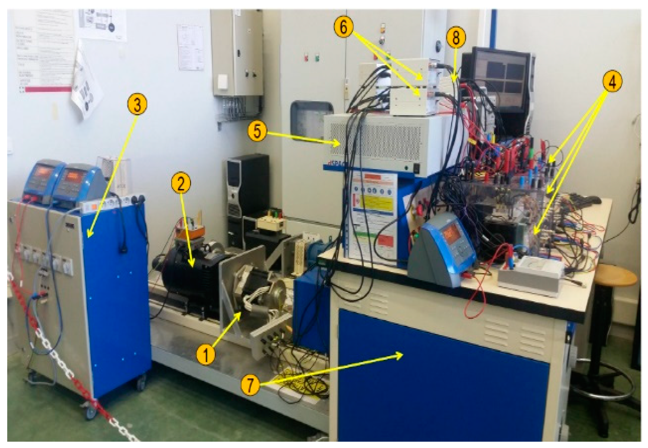
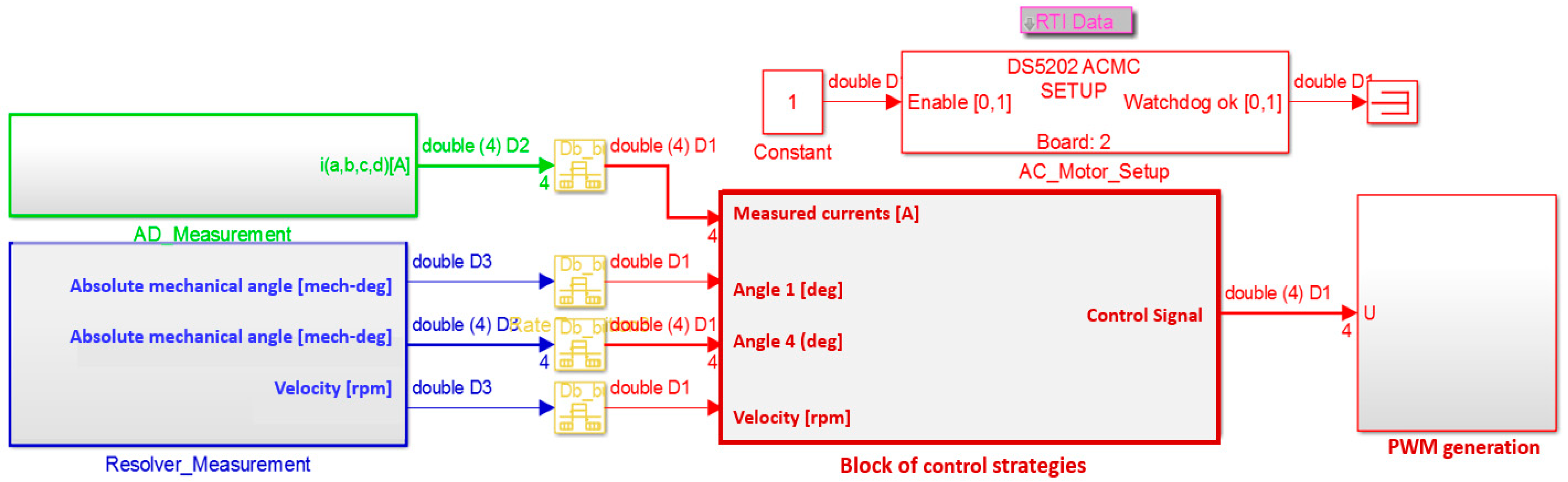
  • Implementation and validation of the three designed controllers [12] on a developed test bench using a multicore dSpace 1005 with a SRM and a DC machine to create a load torque;
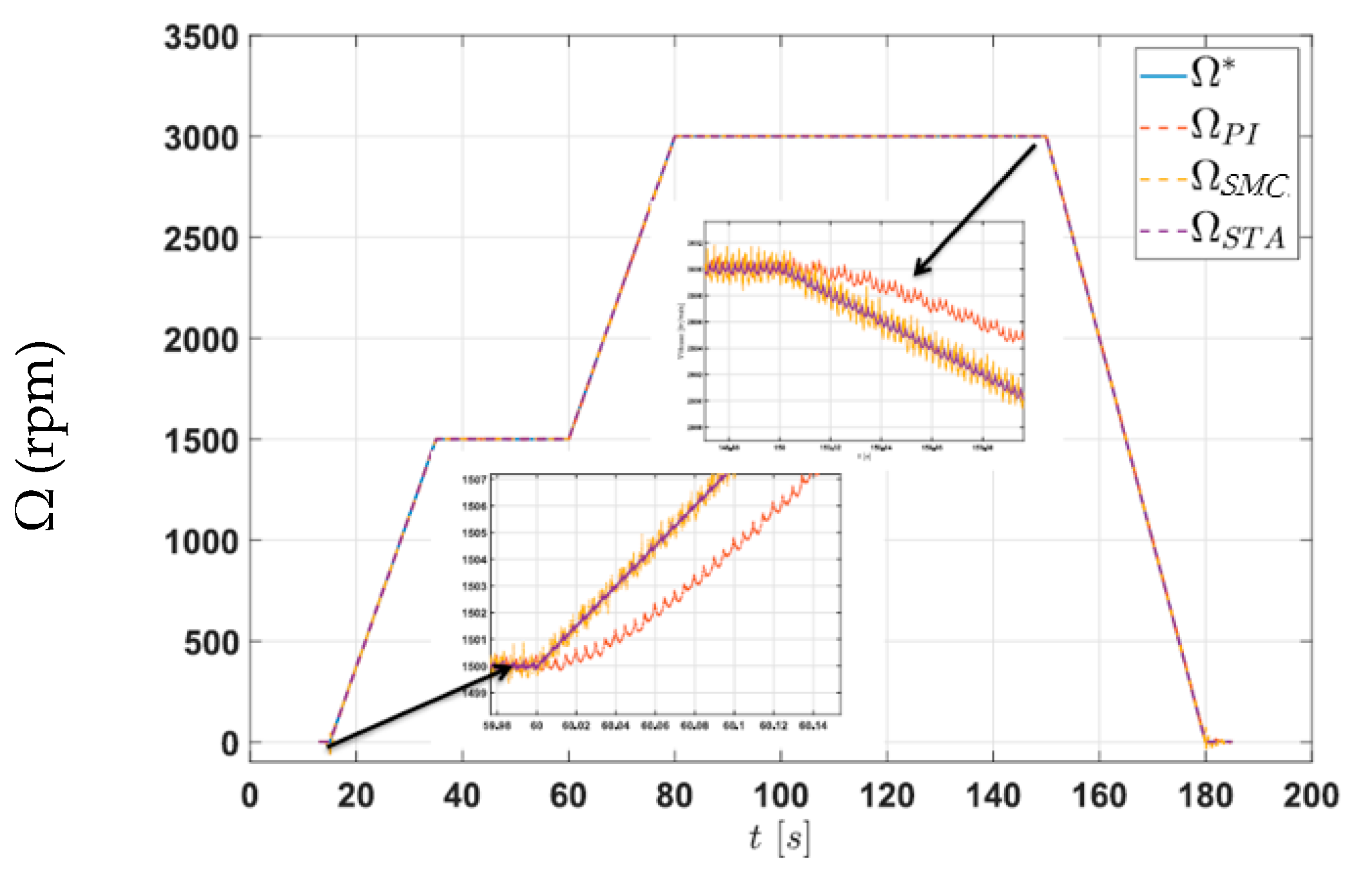
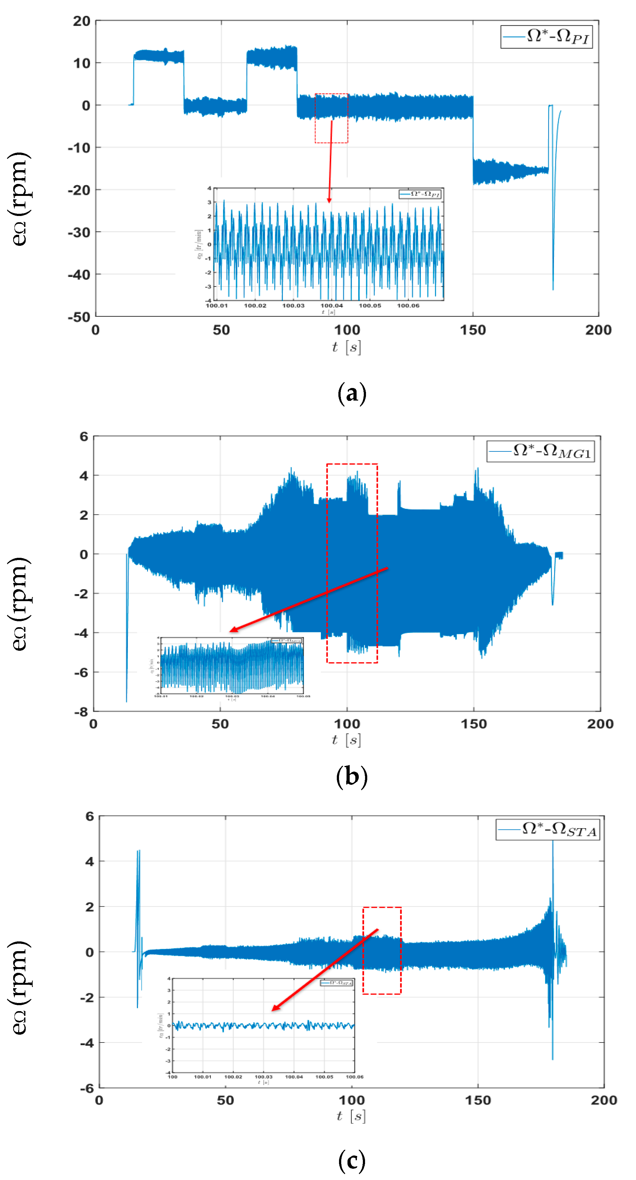
  • Finally, performances comparison is carried with the collected experimental data showing that the Super-Twisting Sliding Mode Control is the best algorithm to select for the improvement of electric vehicle drivetrain performance.
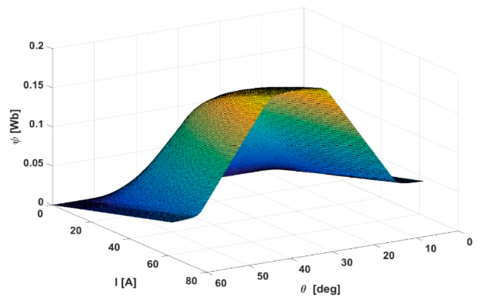
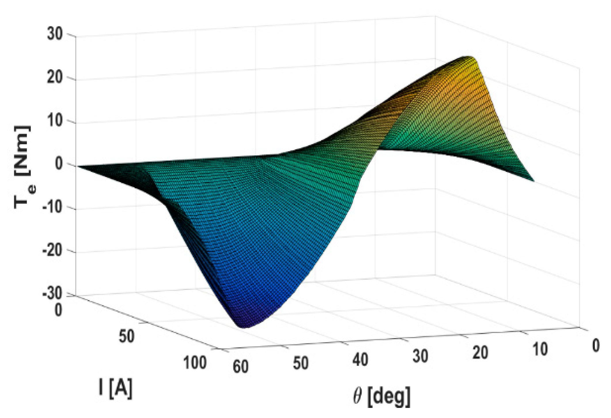
This paper is organized as follows: The model of the SRM and SRM power stage converter are presented in Section 2 and Section 3, respectively. A short description of PI, SMC, and STSMC control design is proposed in Section 4. Section 5 is devoted to the validation of the designed controllers by simulation and the comparison with the PI controllers’ results. Section 6 gives the description of the developed test bench, and the experimental validation of the designed controllers. Conclusion and perspectives are drawn in Section 7.

2. SRM Modeling

The SRM has a simple construction, but the solution of its mathematical model is relatively difficult due to its dominant nonlinear behavior [25] related to the flux linkage and the torque, which both depend on the current phase and the rotor position.
The electromagnetic model of the equivalent circuit of one phase is [3] the following:
V j = R j . I j + ψ j ( θ , I ) t
with j = 1, 2, 3, 4.
The flux linkage ψj of Equation (1) is a nonlinear characteristic depending on two variables: the phase current I (0 to 80A) and the rotor position θ (0 to 60°). In this study, Figure 1 shows the flux linkage characteristics of the used SRM with the topology 8S/6R given in the Appendix A.
The electromechanical model of the SRM associated with a load and viscous friction torques can be expressed as follows [3]:
d d t = 1 J T e θ , I f r T L
The torque Te of Equation (2) is, according to Figure 2, a nonlinear characteristic which depends on the phase current I (0 to 80A) and the rotor position θ (0 to 60°).
The torque Te (Equation (3)) given by Figure 2 is computed from the sum of the instantaneous torque (Equation (4)) developed by phase j according to [3]:
T e = 1 j = 4 T p h a s e j
where:
T p h a s e j = 1 2 d L ( θ ) d θ I j 2
All the variables of the model are given by the following: θ : Rotor position, : Angular velocity of rotor, J : Moment of inertia (rotor), T e : Total electromagnetic torque, f r : Friction Coefficient, T L : Load torque, I j : Current in the jth phase, ψ j : Flux linkages in jth phase, V j : Voltages of jth phase, R j : Resistance of the jth phase, L: Instantaneous inductance.

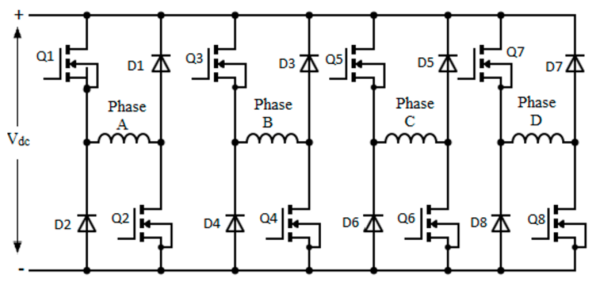
3. SRM Power Stage Converter

As the SRM is four phases, four asymmetric H-bridges are selected to supply the stator windings because of the simple design, control, and low cost. Indeed, different types of converters are listed in the literature to supply the SRM [26]. Figure 3 gives a view of the selected converter supplying each phase of the SRM. The DC link voltage Vdc to supply the converter is fixed according to the SRM specification at 250 V/61 A. The supply of each phase is carried out by each asymmetric H-bridge. On the other hand, PWM signals for supplying the drivers of the transistors are provided by the current loops of the implemented control strategy, which is given in Section 4. Using MATLAB/Simscape, the power stage to supply the SRM is modelized by four asymmetric H-bridges.

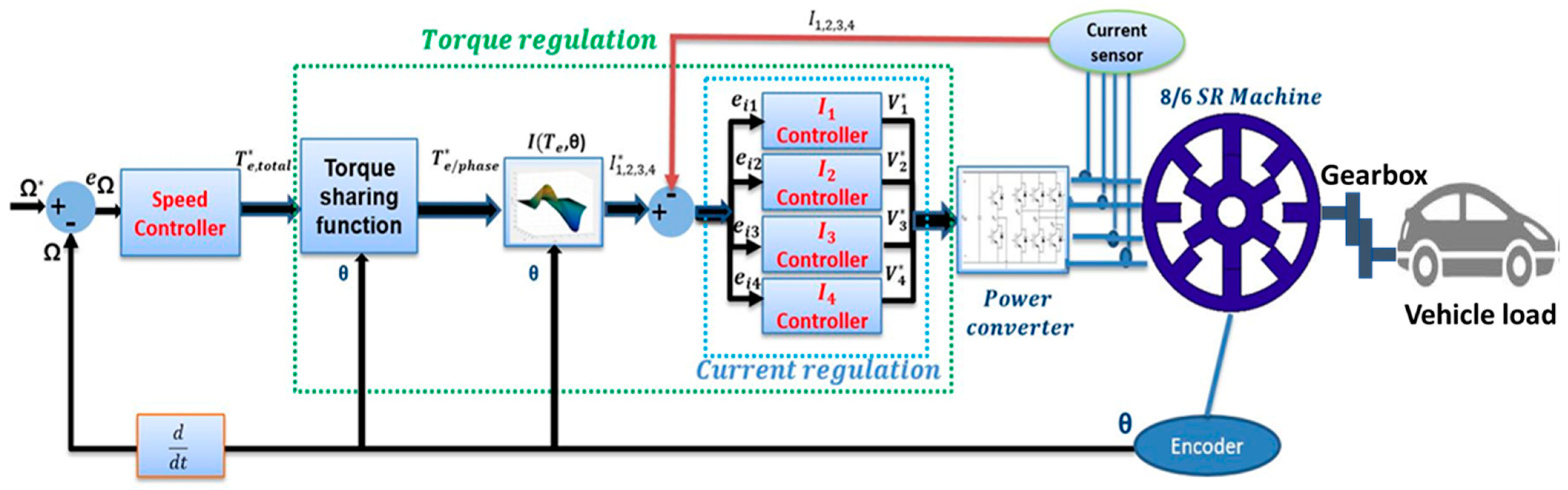
4. SRM Control Strategy

For velocity or torque control, different control strategies are suggested [12]. Direct and indirect torque control are among the control strategies. The control strategy selected for the velocity control is based on two cascade control loops: velocity and current loops [12]. Figure 4 shows the block diagram of this control strategy. The velocity control loop provides, according to the velocity point (*) the total torque setpoint (*) of SRM to a torque sharing function in charge of generating torque setpoint (*) for each phase. From each phase torque setpoint (*), a phase current setpoint (*) is deduced using the reverse of the nonlinear torque characteristics given by Figure 2. The deduced current sept points (*) are finally provided to the four current control loops to generate PWM signals of the converter.
Based on the control strategy given by Figure 4, PI, SMC, and STSMC controllers are designed for velocity and current control loops. SMC and STSM are developed separately for current and velocity control loops in [12] using the nonlinear model of the SRM given in Section 2.

4.1. PI Controllers

PI controllers are widely used in industries due to their simplicity and low cost. Moreover, their implementation in analog or digital hardware is simple and easy. Under limited operating conditions, they perform well and their steady state performance is good. For any PI controller, the control design is defined by the following:
u ( t ) = K p e t + K i 0 t e ( Γ ) d Γ
where e t is the error defined as the difference between the desired set point and the measured variable. K p and K i are the proportional and integral gains.
For the velocity control loop, e t is defined by the following:
e ( t ) = * t t
Ω* and Ω are the velocity set point and the measured velocity, respectively.
For the current loop, e t is given by the following:
e i t = i * t i t
i * and i are the current set point and the measured current, respectively.
The PI parameters Kp and Ki are designed for current and velocity loops using the classical methods of control.

4.2. Sliding Mode Control (SMC)

The design of SMC can be achieved in two steps. In the first step, we define the sliding mode, which is a surface (switching function) that is invariant to the controlled dynamics, where the controlled dynamics are exponentially stable and where the system tracks the desired set point. In the second step, the control law is designed in such a way that it should guarantee steering the system trajectories towards the sliding surface [27].

4.2.1. SMC Controller for Velocity Loop

The switching function is defined as follows:
S 1 ( t ) = e ( t ) + λ 1 t e Γ d Γ
where λ 1 is a positive constant.
The aim is that the error will converge to zero exponentially (if S 1 (t) = 0 then e = 0 ). The state space variables are defined as the following:
x 1 ( t ) = 0 t e Γ d Γ x 2 t = e t   x 1 ˙ ( t ) = x 2 ( t )
Using (8) and (9), we can write the following:
S 1 ( t ) = x 2 t + λ 1 x 1 ( t )
According to (9), the dynamical model of SRM, (2) can be rewritten as follows:
x 2 ˙ = 1 J T e 1 J f r * 1 J f r x 2 * 1 J T L
In a state space representation, (11) becomes the following:
x 1 ˙ = x 2 x 2 ˙ = f t + g . u + d
with f t = 1 J f r Ω * ( t ) 1 J f r e ( t ) Ω * ( t ) , g = 1 J , d = 1 J T L , and u = T e .
The equivalent SMC law ( u e q ) that ensures the asymptotic convergence of the velocity error towards zero verifies the following equality [27]:
S 1 t = S 1 ˙ ( t ) = 0
From (10) and (12), we deduce the equivalent control input as follows:
u e q = g 1 ( f x d λ 1 x 2 )
u e q represents the total reference torque ( T e , t o t a l * ).
Additionally, the discrete SMC law ( u d ) that guarantees the reachability of SMC in finite time is warranted if the following is the case [27]:
S 1 S 1 ˙ < 0
From (10), (15) can be rewritten as the following:
S 1 S 1 ˙ = S 1 ( f x + g . u + d + λ 1 x 2 )
if we set the following:
u d = g . u = g . u d
and
u d =   ( f x + d + λ 1 x 2 )     C 1   s i g n ( S 1 )
where C 1 is a positive constant. Therefore, the SMC law that ensures the asymptotic convergence of the velocity towards zero in finite time is given by the following:
u = u e q + u d

4.2.2. SMC Controller for Current Loop

For the current SMC controller, the sliding surface is defined as the following:
S 2 ( t ) = K 1 e i t + K 2 t e i Γ d Γ
where K 1 and K 2 are two positive coefficients.
The reason for this choice is obvious. If S t = 0 , then e ˙ = K 2 K 1 e , so the current error will converge to zero exponentially.
Equation (1) can be written as follows:
V j = R j . I j + ψ j ( θ , I j ) θ d θ d t + ψ j ( θ , I j ) I j d I j d t
in which d θ d t = , where ψ j ( θ , I j ) I j represents the self-inductance of the phase and ψ j ( θ , I j ) θ is the back counter-electromotive force (EMF) produced in the jth phase. From (21), we can write the following:
d I j d t = ( V j R j . I j ) . I j ψ j ( θ , I j ) I j θ
The equivalent voltage ( V e q ) obtained by the following:
S 2 t = S 2 ˙ ( t ) = 0
From (22) and (23), the equivalent voltage ( V e q ) for each current regulation is written as the following:
V e q = R j I j * + ψ j ( θ , I j ) θ + ψ j ( θ , I j ) I d I j * d t + ( R j ψ j θ , I j I K 2 K 1 ) e i ( t )
Finally, the current SMC controller law is defined as the following:
V S M C = V e q     C 2 s i g n S 2
with C 2 is a positive constant.

4.3. Super Twisting Sliding Mode Control (STSMC)

The implementation of sliding mode control presents an undesirable phenomenon of oscillation, which is known as “chattering”. The Super-Twisting Sliding Mode control (STSMC) has been developed to avoid chattering in variable structure control (VSC) for the case of systems that have a relative degree equal to one [27].
Consider sliding variable dynamics given by a system with a relative degree of two, the following is the case:
y 1 ˙ ( t ) = φ S T ( y 1 , t ) + Υ S T ( y 1 , t ) u S T ( t )
where y 1 ( t ) is the sliding function S , in which φ S T and Υ S T are uncertain functions with the upper and lower bounds of (27) and (28), respectively, and u S T ( t ) is the scalar control input.
φ S T y 1 , t Φ S T
0 < Υ m S T Υ S T y 1 , t Υ M S T
The control signal u S T ( t ) can be given as the sum of two terms [27]:
u = u 1 ( t ) + u 2 ( t )
u 1 ˙ ( t ) = u t S T i f u t S T > U W s i g n y 1 t e l s e
u 2 ( t ) = λ S 0 ρ s i g n y 1 t i f y 1 t > S 0 λ y 1 t ρ s i g n y 1 t e l s e
where U is the control value boundary and S 0 is a boundary layer around the sliding surface S . The sufficient condition of limited time convergence is the following:
W > Φ S T Υ m S T λ 2 > 4 Φ S T Υ m S T 2 Υ M S T ( W + Φ S T ) Υ m S T ( W Φ S T ) 0 < ρ 0.5

4.3.1. STSMC Controller for Velocity Loop

To compare the SMC and STSMC, we use the same switching function expression used in SMC controller design:
S 3 t = y 1 ( t ) = e ( t ) + c t e Γ d Γ , c > 0
The aim of this mathematical development is to write the systems having a relative degree equal to one and to compare it with (26) to find the sufficient conditions and to use the control law defined in (29).
From (2), (33) can be rewritten as the following:
y 1 ˙ = Ω ˙ * + 1 J T L + 1 J f r Ω * + f r J + c e 1 J T e
Defining the variable as the following:
φ S T = Ω ˙ * + 1 J T L + 1 J f r Ω * + f r J + c e
Υ S T = 1
u S T = 1 J T e
Equation (34) becomes the following:
y 1 ˙ = φ S T + Υ S T u S T
If we set the following:
0 < Υ m S T = 0.5 Υ S T = 1 Υ M S T = 2 u S T = 1 J T e < U = 1 J T M a x Φ S T = Ω * ˙ + T L J + f r Ω * J + f r J + c e + T e J
where T M a x is the maximum torque of the SRM. Conditions in (27) and (28) are satisfied.
To design the control law defined in (29), it is necessary to choose the controller parameters that verify (32).

4.3.2. STSMC Controller for Current Loop

In the same way as in the previous paragraph, for the STSMC current controller, the switching surface is defined as the following:
S 4 t = y 2 ( t ) = K 3 e i t + K 4 t e i Γ d Γ
Putting e i t with its expression (21) in (38), we can write the following:
y 2 ˙ = K 3 e i * + K 4 e i + K 3 R j . I j I j ψ j ( θ , I j ) K 3 I j θ + I j ψ j θ , I j V j
where K 3 and K 4 are two positive numbers.
Defining the variable as the following:
φ S T = K 3 e i * + K 4 e i + K 3 R j . I j I j ψ j ( θ , I j ) K 3 I j θ
Υ S T = I j ψ j θ , I j
u S T = V j
Equation (41) is expressed as the following:
y 2 ˙ = φ S T + Υ S T u S T
where
0 < Υ m S T = 0.5 I j ψ j θ , I j Υ S T = I j ψ j θ , I j Υ M S T = 2 I j ψ j θ , I j u S T = V j < U = V Φ S T = K 3 e i * + K 4 e i + K 3 R j . I j I j ψ j θ , I j + K 3 I j θ
It satisfies the conditions in (27) and (28).

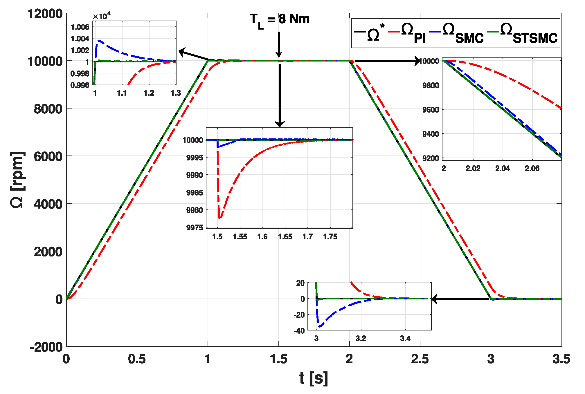
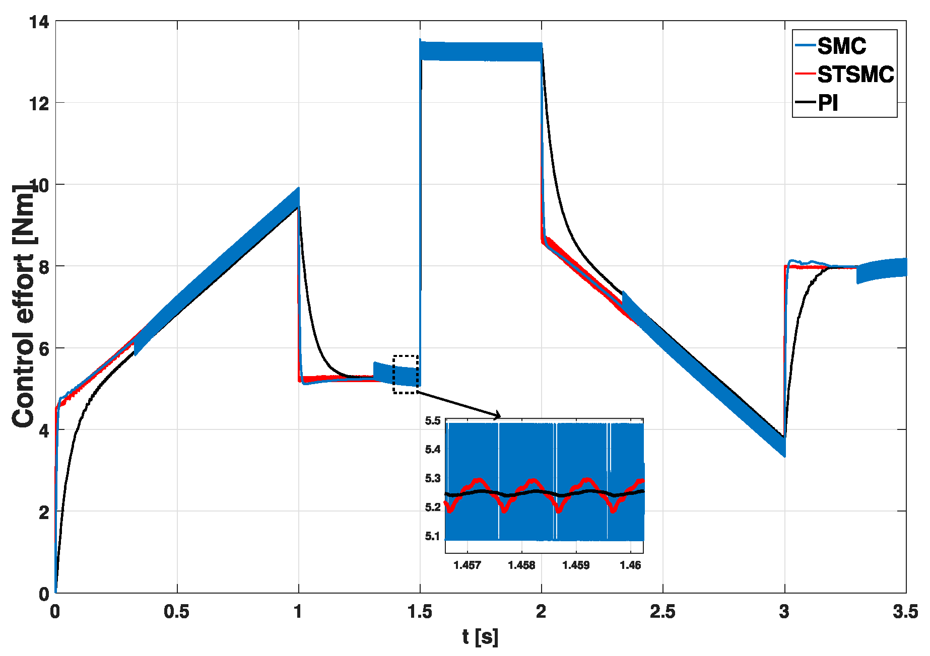
5. Performances of the Designed Controllers

For the velocity and current loops, controllers are designed for both using PI Controllers, Sliding Mode Controller (SMC), and Super-Twisting Sliding Mode Controller (STSMC). Simulations are performed at a reduced scale for a vehicle drivetrain (Figure 4) using Matlab/Simulink to evaluate the proposed controllers [12]. The objectives are to minimize the velocity error and to ensure a smooth total torque waveform of the SRM. A velocity profile from zero to SRM maximum velocity (10,000 rpm) is chosen (Figure 5) with a load torque T L = 8 Nm applied, in steady state, at t = 1.5 s, for a duration of 2 s. In addition, SRM torque viscous friction defined by fr*Ω where fr is the viscous friction coefficient (see Appendix A) is considered for all the simulation. The velocity profile tracking of the PI, SMC, and STSMC controllers and torques responses are presented in Figure 5 and Figure 6, respectively. Indeed, Figure 5 shows that the velocity profile is well followed using the three controllers except the PI controller. Indeed, with the zooms displayed in Figure 5, STSM control is the best in terms of tracking. In Figure 6, the torque responses confirm on the one hand that the STSM control is the best, in terms of response time, to follow the torque profile, and on the other hand, as shown in the zoom of Figure 6, the torque ripple is considerably reduced in steady state compared to the SMC. In addition, the motor torque (current) at standstill is not zero because of the applied load torque of 8Nm for a duration of 3 s. However, viscous friction torque is zero because it depends on the motor velocity.
Based on these simulation results, Table 1 summarizes performances of the three controllers, namely rise time, maximum steady state error, maximum overshoot of velocity responses given by Figure 5, and torque ripples computed from torques responses given by Figure 6. Finally, performances comparison is carried out to show that Super-Twisting Sliding Mode Control is the best algorithm to provide the best performances for an electric vehicle drivetrain using a Switched Reluctance Machine.

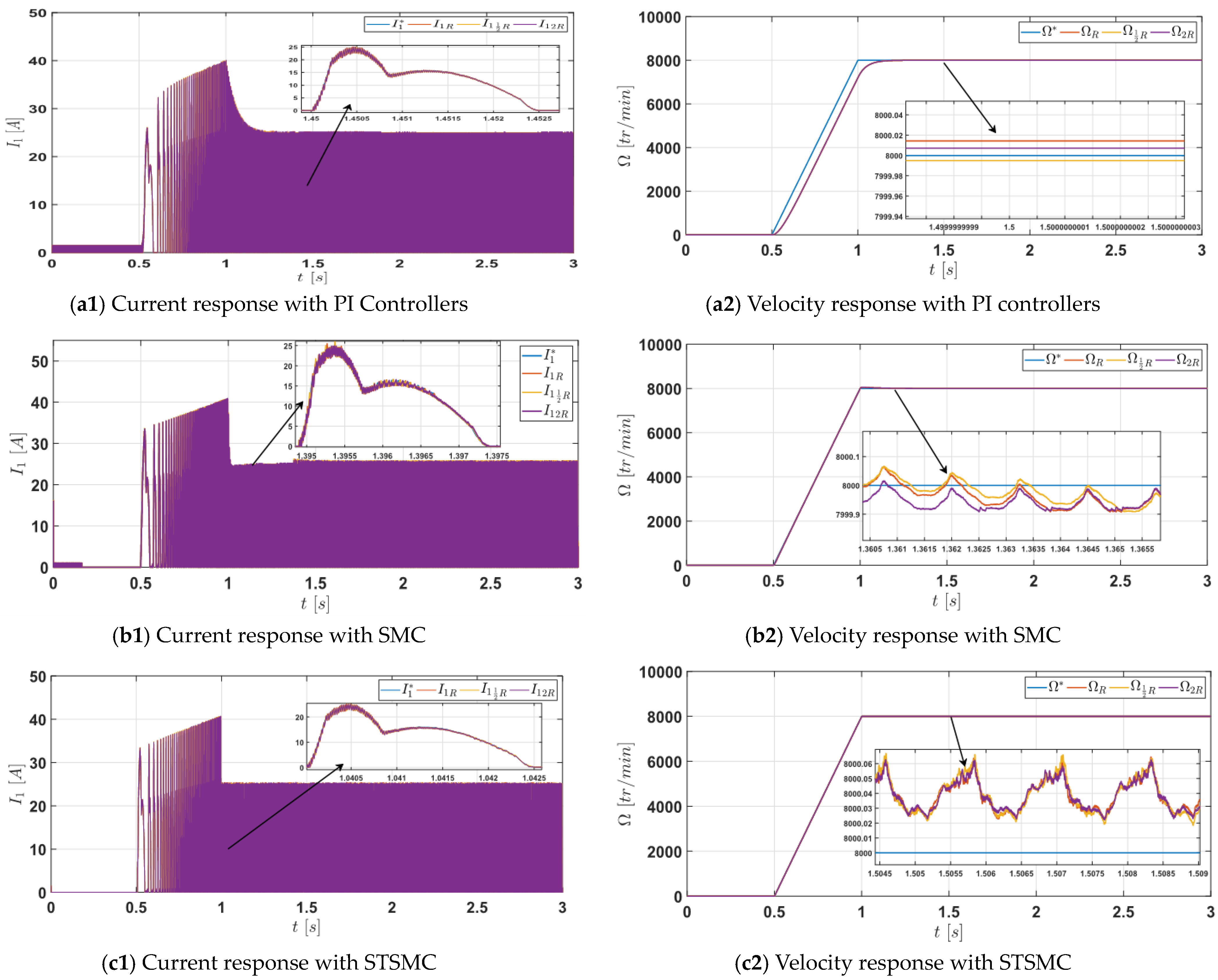
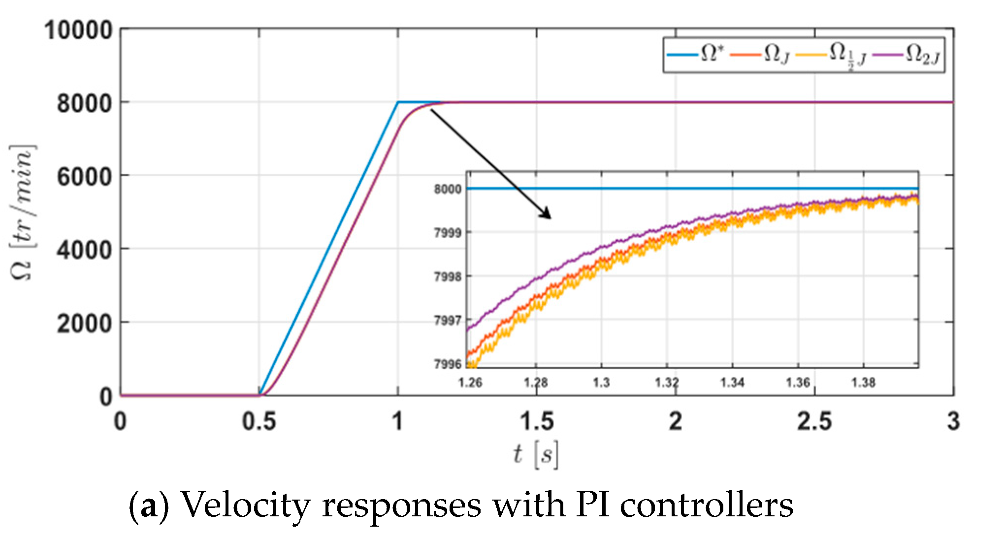
6. Robustness of the Designed Controllers

In the context of an electric vehicle application, the study of the robustness of the proposed controllers is necessary to check the limits of performances degradation with respect to the variations of the SRM physical parameters. The parameters to be varied are the resistance of the stator windings of a phase, the moment of inertia, the viscous friction coefficient, and the vehicle load torque whose variations are due to driving conditions (acceleration/deceleration), road slope, and state of the road (speed bumps, presence of obstacles, etc.). Based on the designed controllers where performances are evaluated by simulation in [12], a second simulation creating the variation of physical parameters of the vehicle drivetrain is carried with the designed controllers PI, SMC, and STSMC.

6.1. Stator Resistance Windings Variation

As the stator resistance windings varies because of temperature and ageing of the SRM, two values are chosen with −50% and +100% of the nominal value. Using the same simulator with the three controllers, namely PI, SMC and STSMC, response velocities and stator currents responses are collected. Figure 7a (with PI control), Figure 7b (with SMC), and Figure 7c (with STSMC) show the effect of these variations. Indeed, if the stator resistance of a phase decreases, an overshoot occurs; if the stator resistance of a phase increases, dynamic responses are slow. In addition, the zooms associated with these figures for the current and velocity responses show the interest to use the STSMC for the resistance varyies.

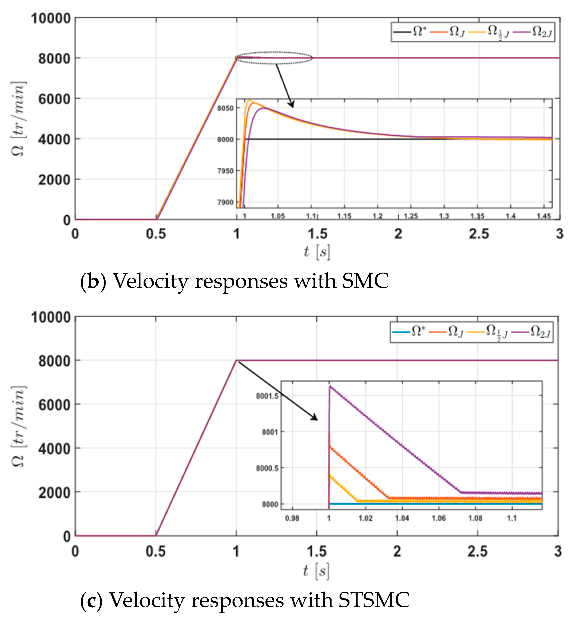
6.2. Load Inertia Variation

As the vehicle inertia varies because of the vehicle load inertia, two values are chosen with −50% and +100% from the SRM inertia nominal value. Velocity responses show the effect of these variation on the velocity responses with the PI controller (Figure 8a), SMC (Figure 8b), and STSM (Figure 8c).

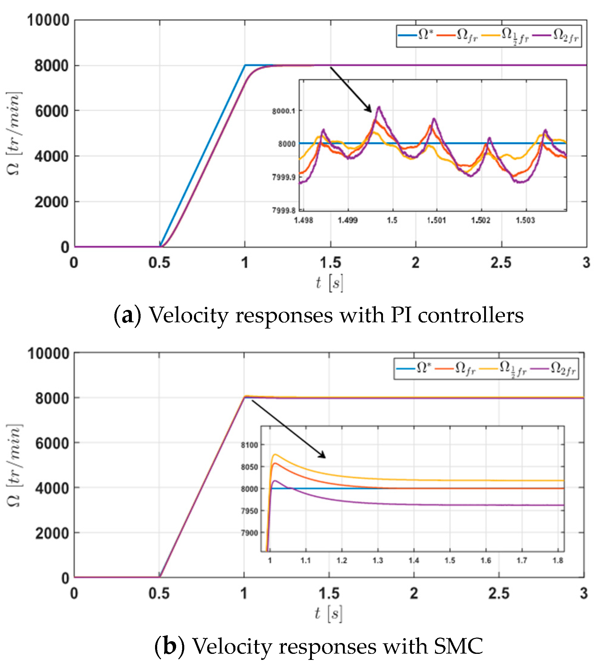
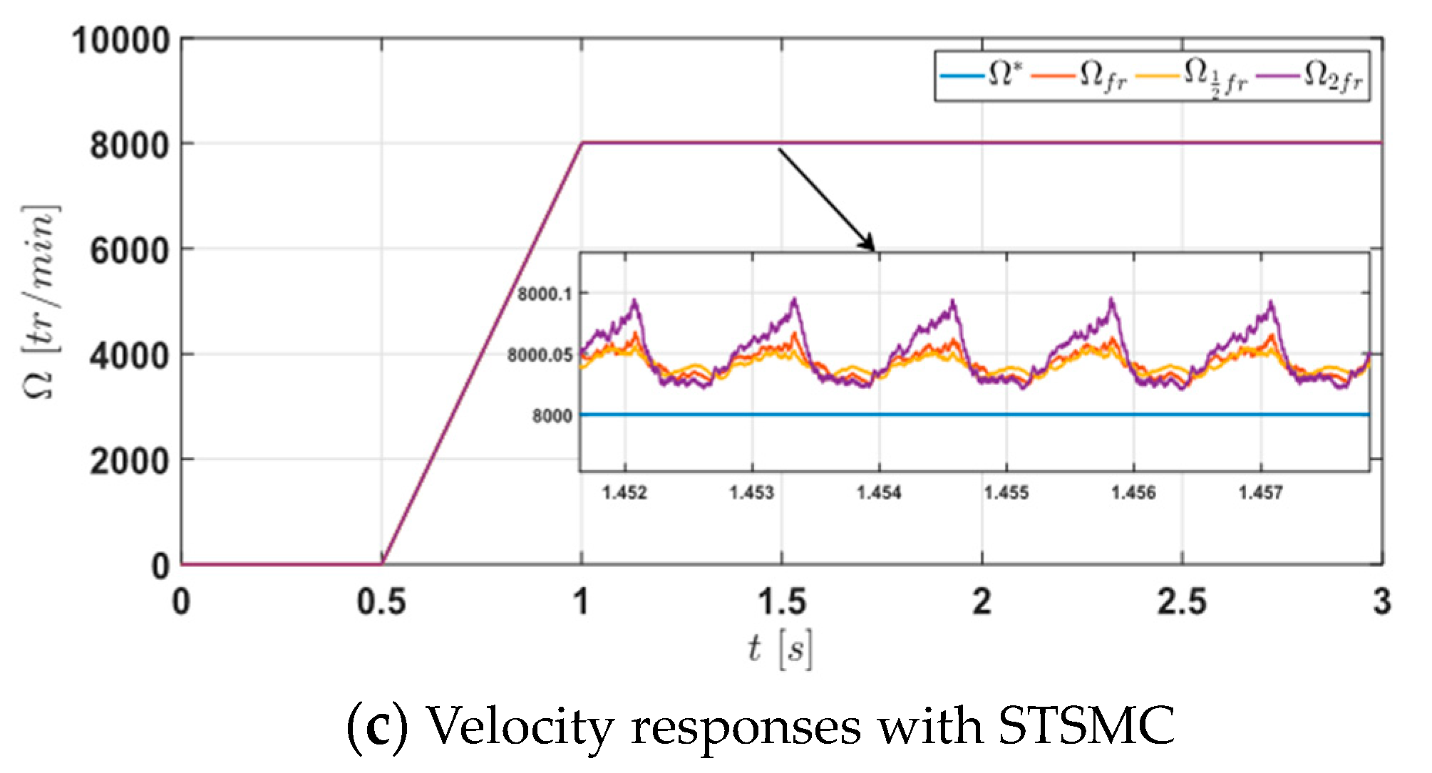
6.3. Viscous Friction Coefficient Variation

For the viscous friction coefficient, a variation of ½ fr and 2 fr of the friction coefficient is carried out by simulation using the three controllers. Figure 9a–c show the velocity and torque responses. Indeed, STSMC is more robust compared to the other controllers. The zooms show that the errors are neglected when the viscous friction coefficient varies.

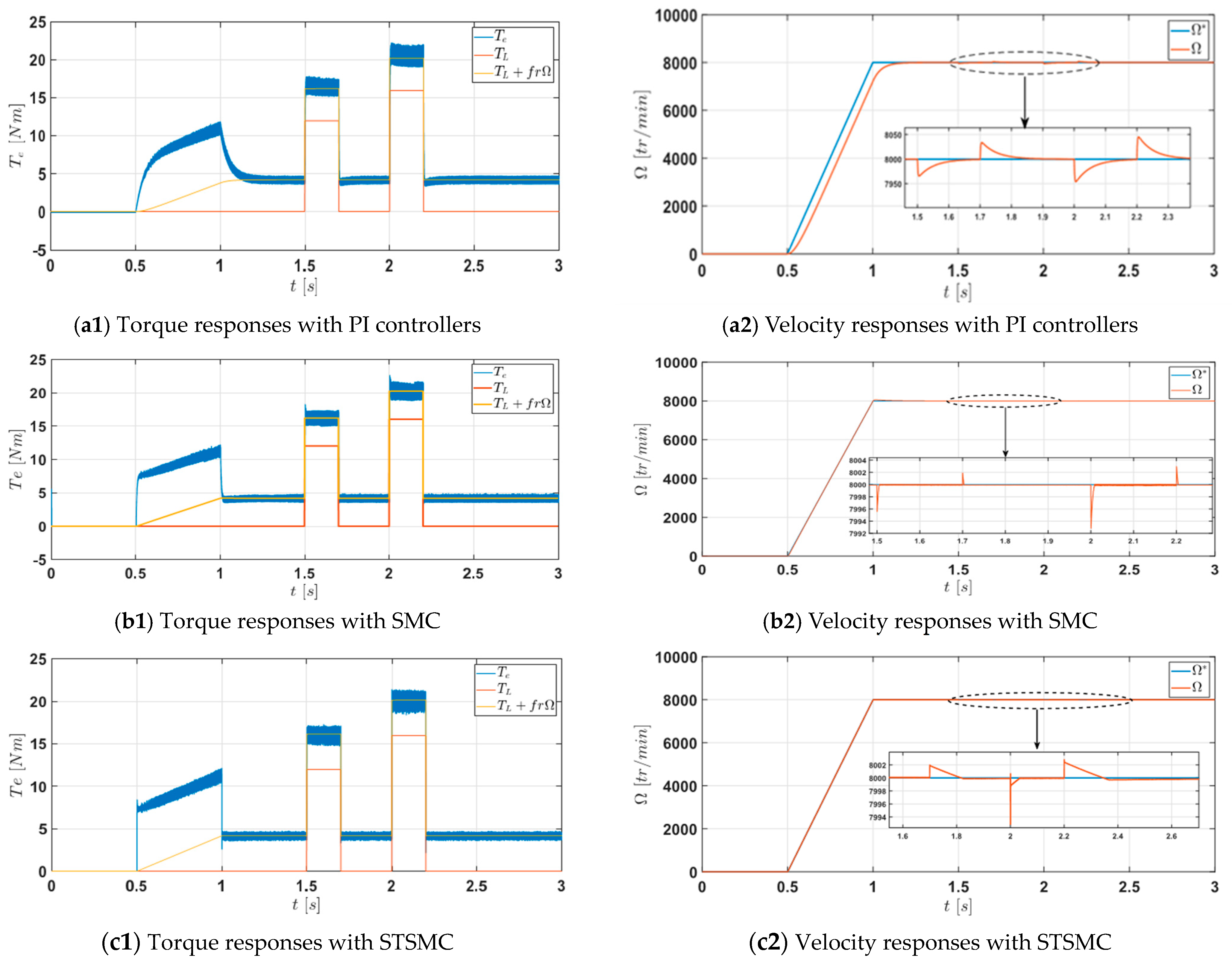
6.4. Load Torque Variation

For load torque variation, a first step load torque of 12 Nm is applied at t = 1.5 s and a second step of 16 Nm is applied at t = 2 s. Figure 10a–c show torque and velocity responses using the three controllers. Indeed, the load torque change is well compensated by the motor torque. In addition, as shown in the zoom of velocity responses, the overshoot error is neglected.
Based on the responses of Figure 7, Figure 8, Figure 9 and Figure 10, a quantification of the maximum error in steady state is carried out for current and velocity responses, while from torque responses, torque error is quantified in % using the following formula:
Δ T e ( % ) = T e m a x T e m i n T e a v e r a g e
Table 2 summarizes the computed values of the maximum errors at the maximum velocity using PI control, SMC, and STSMC.
In comparing the maximum errors of the three controllers, STSMC also shows its added value in robustness. Indeed, for all physical parameter variations, the maximum errors are the smallest ones for velocity, current, and torque responses. However, STSMC remains the best controller in terms of performance and robustness for electric vehicle applications. Finally, in Table 3, performance and robustness of the three controllers shows that Super-Twisting Sliding Mode Control is the best comparing to the PI and sliding mode controllers.

7. Experimental Validation

For the experimental validation, an emulation of the electric vehicle drivetrain is carried out at a reduced scale. As shown in Figure 11, a test bench is set up using a Switched Reluctance Machine of 8.3 kW (1) and a DC machine (2) with a resistive load (3) to emulate the vehicle load torque. The power supply of SRM is provided by four asymmetric half-bridges (4) supplied by a DC link of 250 V (7). In addition, the PWM signals to provide to the drivers of the IGBTs of each half-bridge converter are computed from the control strategies implemented on a multicore dSpace 1005 platform (5). The provided PWM signals are amplified from 5 V to 15 V using an electronic stage (8). For all the implemented control strategies, four current sensors (6) are used to provide, in real time, the stator currents through A/D inputs of the dSpace panel.
The real-time interface RTI of the implemented control strategies is mainly composed of four blocks. Figure 12 gives the general block scheme of the implemented control strategies, namely PI, SMC, and STSMC with a sample time of 10−5 s and a PWM frequency of 18 kHz.
For the experimental validation, a velocity profile (*) of 3000 rpm max is chosen with acceleration, steady state, and deceleration phases for a duration of 180 s. Based on the velocity responses of Figure 13, responses errors are plotted in Figure 14a–c showing, respectively, a zoom of the reached velocity in steady state errors with PI, SMC, and STSMC.
Indeed, the best robust control given the minimum of oscillations around the steady state value is STSMC and, consequently, the minimum error in a steady state compared to other controllers. Moreover, when comparing the response of SMC and STA, the velocity response ripples, as shown in the zooms of Figure 13, are significantly improved due to the elimination of the chattering phenomenon.
Finally, simulation and experimental results confirm that, according to the performance comparison, STSMC is the best algorithm to be selected for an electric vehicle drivetrain with a Switched Reluctance Machine.
For the same controllers, current responses for a current set point (*) are collected from the test bench and plotted to make a performance comparison. Figure 15, Figure 16 and Figure 17 show the current responses of phase 1 using PI, SMC, and STSMC, while Figure 18, Figure 19 and Figure 20 show the corresponding current error responses.
According to the experimental current responses, it is shown that STSMC implemented in the current loop is the best algorithm to obtain minimum oscillations around the steady state value and, consequently, minimum torque ripple. Finally, the three robust controllers implemented simultaneously in the velocity loop and in the four current loops of the SRM control strategy confirm that STSMC performances are better compared to the other robust controls, namely PI and SM controllers.

8. Conclusions

In this paper, STSMC, SMC, and PI controllers are successfully validated and implemented to deal simultaneously with the velocity and current tracking problem of a Switched Reluctance Machine for electric vehicle applications. A cascade control strategy is adopted to control separately the SRM velocity and each phase current.
  • The simulation and the experimental results show and confirm the benefits of using STSMC in terms of tracking performances and torque ripple minimization, thanks to the significant reduction in the chattering.
  • The performances of electric vehicle drivetrain are improved using a Switched Reluctance Machine and STSMC. Both could be a new solution for future electric vehicles drivetrains: SRM as a fault-tolerant design component without rare earth material and STSMC as a robust control to obtain better performances and comfort in the electric vehicle.
  • Improvement of performances and robustness of electric vehicle drivetrain using switched reluctance machine can improve performances of other functions of safety in electric vehicle applications and/or in autonomous vehicles where the dynamic behavior of the vehicle on the road depends on the dynamic behavior of the vehicle drivetrain in closed loop.
  • This work can be extended to deal with electric and mechanical faults of the electric vehicle drivetrain to show the added value of SRM as a fault tolerant design machine.
  • Finally, this study can be extended to Four-Wheel Independent Control Electric Vehicles (FWIC-EV) using Switched Reluctance Machines and STSMC.

Author Contributions

Validation, Y.S.; Writing—original draft, R.S.; Writing—review & editing, A.A. All authors have read and agreed to the published version of the manuscript.

Funding

This research received no external funding.

Data Availability Statement

Not applicable.

Conflicts of Interest

The authors declare no conflict of interest.

Appendix A

ParameterValue
Topology8 S/6 R
Phase number4
Power supply (DC)250 V
Maximum current61 A
Nominal Power 8 kW
Maximum torque T M a x 20 Nm
Maximum speed10,000 rpm
Phase resistance R0.0404 Ohm
Moment of inertia J0.0043 Kg/m2
Viscous friction coefficient fr0.005 Nm/s

References

  1. Husain, I. Electric and Hybrid Vehicles: Design Fundamentals; CRC Press: Boca Raton, FL, USA, 2003. [Google Scholar]
  2. Widmer, J.D.; Martin, R.; Kimiabeigi, M. Electric vehicle traction motors without rare earth magnets. Sustain. Mater. Technol. 2015, 3, 7–13. [Google Scholar] [CrossRef] [Green Version]
  3. Krishnan, R. Switched Reluctance Motor Drives: Modeling, Simulation, Analysis, Design, and Applications; CRC Press: Boca Raton, FL, USA, 2001. [Google Scholar]
  4. Biczyski, M.; Sehab, R.; Whidborne, J.; Krebs, G.; Luk, P. Fault-tolerant Switched Reluctance Motor Propulsion System for eVTOLs. In Proceedings of the 12th EASN International Conference on “Innovation in Aviation & Space for opening New Horizons, Barcelona, Spain, 18–21 October 2022. [Google Scholar]
  5. Colby, R.S.; Mottier, F.M.; Miller, T.J.E. Vibration modes and acoustic noise in a four-phase switched reluctance motor. IEEE Trans. Ind. Appl. 1996, 32, 1357–1364. [Google Scholar] [CrossRef] [Green Version]
  6. Chiba, A.; Kiyota, K.; Hoshi, N.; Takemoto, M.; Ogasawara, S. Development of a Rare-Earth-Free SR Motor With High Torque Density for Hybrid Vehicles. IEEE Trans. Energy Convers. 2015, 30, 175–182. [Google Scholar] [CrossRef]
  7. Takiguchi, M.; Sugimoto, H.; Kurihara, N. Acoustic Noise and Vibration Reduction of SRM by Elimination of Third Harmonic Component in Sum of Radial Forces. IEEE Trans. Energy Convers. 2015, 30, 883–891. [Google Scholar] [CrossRef]
  8. Rana, A.K.; Raviteja, A. A mathematical torque ripple minimization technique based on nonlinear modulating factor for switched reluctance motor drives. IEEE Trans. Ind. Electron. 2022, 69, 1356–1366. [Google Scholar] [CrossRef]
  9. Ding, W.; Liu, G.; Li, P. A hybrid control strategy of hybridexcitation switched reluctance motor for torque ripple reduction and constant power extension. IEEE Trans. Ind. Electron. 2020, 67, 38–48. [Google Scholar] [CrossRef]
  10. Sun, X.; Wu, J.; Lei, G.; Guo, Y.; Zhu, J. Torque ripple reduction of srm drive using improved direct torque control with sliding mode controller and observer. IEEE Trans. Ind. Electron. 2021, 68, 9334–9345. [Google Scholar] [CrossRef]
  11. Kelly, L.; Cossar, C.; Miller, T. Electronic Control of Switched Reluctance Machines; Newnes Power Engineering Series; Newnes: Oxford, UK, 2001. [Google Scholar]
  12. Saadi, Y.; Sehab, R.; Chaibet, A.; Boukhnifer, M.; Diallo, D. Performance comparison between conventional and robust control for the powertrain of an Electric Vehicle propelled by a Switched Reluctance Machine. In Proceedings of the IEEE Vehicle Power and Propulsion Conference (VPPC), Arlington, TX, USA, 9–12 September 2007; pp. 1–6. [Google Scholar]
  13. Hannoun, H.; Hilairet, M.; Marchand, C. Gain-scheduling pi current controller for a switched reluctance motor. In Proceedings of the IEEE International Symposium on Industrial Electronics, Vigo, Spain, 4–7 June 2007; pp. 1177–1182. [Google Scholar]
  14. Ouddah, N.; Boukhnifer, M.; Chaïbet, A.; Monmasson, E. Robust LPV current control of switched reluctance motor. In Proceedings of the 22nd Mediterranean Conference on Control and Automation, Palermo, Italy, 16–19 June 2014. [Google Scholar]
  15. Ghani, M.; Frah, N.; Tamjis, M. Vector Control of Switched Reluctance Motor Using Fuzzy Logic and Artificial Neutral Network. In Proceedings of the International Conference on Electrical, Electronics, and Optimization Techniques (ICEEOT), Chennai, India, 3–5 March 2016; pp. 4412–4417. [Google Scholar]
  16. Ling, F.; Ma, M.; Yang, Q.; Li, F. Torque Ripple Reduction of Switched Reluctance Motor by Segmented Harmonic Currents Injection Based on Adaptive Fuzzy Logic Control. In Proceedings of the 14th IEEE Conference on Industrial Electronics and Applications (ICIEA), Xi’an, China, 19–21 June 2019. [Google Scholar]
  17. John, G.; Eastham, A. Speed control of switched reluctance motor using sliding mode control strategy. In Proceedings of the IAS ’95. Conference Record of the 1995 IEEE Industry Applications Conference Thirtieth IAS Annual Meeting, Orlando, FL, USA, 8–12 October 1995; Volume 1, pp. 263–270. [Google Scholar]
  18. Ruiwei, Z.; Xisen, Q.; Liping, J.; Yingch, Z.; Jintong, N. An adaptive sliding mode current control for switched reluctance motor. In Proceedings of the IEEE Conference and Expo Transportation Electrification Asia-Pacific (ITEC Asia-Pacific), Beijing, China, 31 August–3 September 2014. [Google Scholar]
  19. Canale, M.; Fagiano, L.; Ferrara, A.; Vecchio, C. Comparing Internal Model Control and Sliding-Mode Approaches for Vehicle Yaw Control. IEEE Trans. Intell. Transp. Syst. 2009, 10, 31–41. [Google Scholar] [CrossRef]
  20. Ouddah, N.; Boukhnifer, M.; Chaibet, A.; Monmasson, E. Robust controller designs of switched reluctance motor for electrical vehicle. In Proceedings of the 22nd Mediterranean Conference on Control and Automation, Palermo, Italy, 16–19 June 2014. [Google Scholar]
  21. Peng, F.; Emadi, A. A digital PWM current controller for switched reluctance motor drives. In Proceedings of the IEEE Transportation Electrification Conference and Expo (ITEC), Dearborn, MI, USA, 15–18 June 2014; pp. 1–6. [Google Scholar]
  22. Li, X.; Shamsi, P. Model Predictive Current Control of Switched Reluctance Motors with Inductance Auto-Calibration. IEEE Trans. Ind. Electron. 2016, 63, 3934–3941. [Google Scholar] [CrossRef]
  23. Liu, W.; Xiong, L.; Xia, X.; Lu, Y.; Gao, L.; Song, S. Vision-aided intelligent vehicle sideslip angle estimation based on a dynamic model. IET Intell. Transp. Syst. 2020, 14, 1183–1189. [Google Scholar] [CrossRef]
  24. Liu, W.; Xiong, L.; Xia, X.; Yu, Z. Intelligent vehicle sideslip angle estimation considering measurement signals delay. In Proceedings of the IEEE Intelligent Vehicles Symposium (IV), Changshu, China, 26–30 June 2018; pp. 1584–1589. [Google Scholar]
  25. Husain, I.; Hossain, S. Modeling, Simulation, and Control of Switched Reluctance Motor Drives. IEEE Trans. Ind. Electron. 2005, 52, 1625–1634. [Google Scholar] [CrossRef]
  26. Pollock, C.; Williams, B. A unipolar converter for a Switched Reluctance Motor. IEEE Trans. Ind. Appl. 1990, 26, 222–228. [Google Scholar] [CrossRef]
  27. Bartolini, G.; Ferrara, A.; Usai, E. Chattering avoidance by second order sliding mode control. IEEE Trans. Autom. Control 1998, 43, 241–246. [Google Scholar] [CrossRef]
Figure 1. Flux in terms of position and phase current.
Energies 16 03212 g001
Figure 2. Torque in terms of position and phase current.
Energies 16 03212 g002
Figure 3. SRM four asymmetric H-bridges.
Energies 16 03212 g003
Figure 4. Block diagram of the control strategy.
Energies 16 03212 g004
Figure 5. Velocity responses for the designed controllers.
Energies 16 03212 g005
Figure 6. Torque responses for the designed controllers.
Energies 16 03212 g006
Figure 7. Velocity and current responses with the three controllers.
Energies 16 03212 g007
Figure 8. Velocity responses with the three controllers.
Energies 16 03212 g008aEnergies 16 03212 g008b
Figure 9. Velocity responses with the three controllers.
Energies 16 03212 g009aEnergies 16 03212 g009b
Figure 10. Velocity and torque responses with the three controllers.
Energies 16 03212 g010
Figure 11. Test bench SRM-DC machine.
Energies 16 03212 g011
Figure 12. RTI block scheme of the implemented control strategies. 1—block of the four measured currents ia, ib, ic, and id. 2—block of the measured position and velocity with a resolver mounted on the shaft of the SRM. 3—block of the control strategies with the designed robust controllers; PI, SMC, and STSM implemented separately. 4—block of PWM signal generation.
Energies 16 03212 g012
Figure 13. Velocity responses of the implemented robust controllers.
Energies 16 03212 g013
Figure 14. Zoom on the velocity responses in steady state.
Energies 16 03212 g014
Figure 15. Current response of phase 1 using PI control.
Energies 16 03212 g015
Figure 16. Current response of phase 1 using SMC.
Energies 16 03212 g016
Figure 17. Current response of phase 1 using STSMC.
Energies 16 03212 g017
Figure 18. Current error response of phase 1 using PI control.
Energies 16 03212 g018
Figure 19. Current error response of phase 1 using SM.
Energies 16 03212 g019
Figure 20. Current error response of phase 1 using STSMC.
Energies 16 03212 g020
Table 1. Performances comparison of the designed controllers.
Performances PISMCSTSMC
Rise time0.105 s0.08 s0.01 s
Max of steady state error6%0.3%0.1%
Max of overshoot27‰23‰8‰
Torque ripple at maximum velocity14.5%13.9%12%
Table 2. Evaluation of the robustness of the three controllers.
Physical Parameter VariationPISMCSTSMC
Resistance R Velocity emax = 2 rpmVelocity emax = 0.8 rpmVelocity emax = 0.5 rpm
Current emax = 1.3 ACurrent emax = 0.97 ACurrent emax = 0.3 A
Moment of inertia J Velocity emax = 5 rpmVelocity emax = 5 rpmVelocity emax = 1.5 rpm
Friction   Coefficient   f r Velocity emax = 3 rpmVelocity emax = 40 rpmVelocity emax = 0.5 rpm
load   torque   T L Velocity emax = 48 rpmVelocity emax = 8 rpmVelocity emax = 5 rpm
Torque emax in % = 0.6Torque emax in % = 0.1Torque emax in % = 0.06
Table 3. Performances and robustness evaluation of the three controllers.
Controller
PISMCSTSMC
PerformancesTracking-++++
Rapidity+++++
Precision+++++
Torque ripple+-++
RobustnessR++++
fr++++
J+++++
TL+++++
++: Very good, +: Good, -: Poor.
Disclaimer/Publisher’s Note: The statements, opinions and data contained in all publications are solely those of the individual author(s) and contributor(s) and not of MDPI and/or the editor(s). MDPI and/or the editor(s) disclaim responsibility for any injury to people or property resulting from any ideas, methods, instructions or products referred to in the content.

