Article

The Effect of Boost Coil and Alignment of Transmitting and Receiving Coils on Transmission Efficiency in EV Wireless Power Transfer Systems

1
Optical Precision Measurement Research Center, Korea Photonics Technology Institute, Gwangju 61007, Republic of Korea
2
Department of Electrical Engineering, Chonnam National University, Gwangju 61186, Republic of Korea
*
Author to whom correspondence should be addressed.
Energies 2023, 16(7), 3213; https://doi.org/10.3390/en16073213
Submission received: 6 March 2023 / Revised: 27 March 2023 / Accepted: 31 March 2023 / Published: 3 April 2023

Abstract

:
As the electric vehicle (EV) market continues to grow, wireless charging technologies are constantly evolving. Considering the limitations of traditional charging methods, the adoption of wireless charging technology is an essential strategy, and the distribution of wireless charging systems is expected to accelerate in the global market with initiatives such as international standards for wireless charging systems. With regard to this technological trend, this study experimentally analyzed the effects of the boost coil and the alignment of the transmitting and receiving coils on the transmission efficiency in wireless power transfer systems. The boost coil amplifies the magnetic field using a high-frequency signal and transfers the field to the receiving coil. Moreover, simulations were conducted based on the theory that using the boost coil could increase the efficiency of wireless power transfer, and the impact of the alignment between the transmitting and receiving coils on the transmission efficiency was also analyzed.

1. Introduction

Wireless Power Transmission (WPT) systems for electric vehicles (EVs) are emerging technologies that are attracting considerable attention due to their potential to overcome the limitations of traditional charging methods. The WPT system uses electromagnetic waves to transfer power from the charging infrastructure to the EV’s battery pack without physical contact. This allows you to charge the EV by simply parking it on the wireless charging pad, making the charging process more convenient and efficient.
Currently, the market [1] for wireless charging systems for EVs is growing rapidly, and many companies are investing in research and development of this technology, and wireless power transmission standards [2] for EVs, such as SAE J2954, enable interoperability between different wireless charging systems. This ensures the safety and efficiency of wireless charging systems, enabling manufacturers to develop interoperable systems and facilitate widespread adoption of wireless charging technologies for EVs.

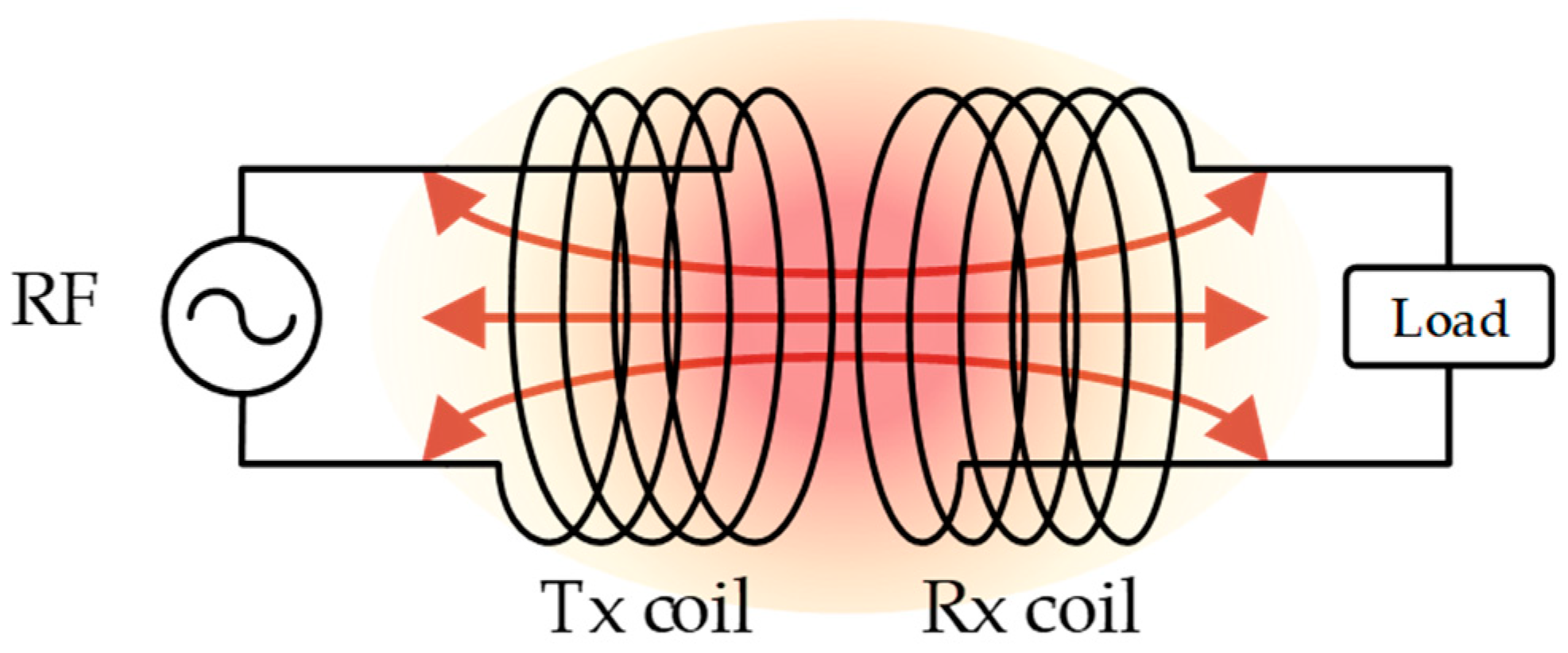
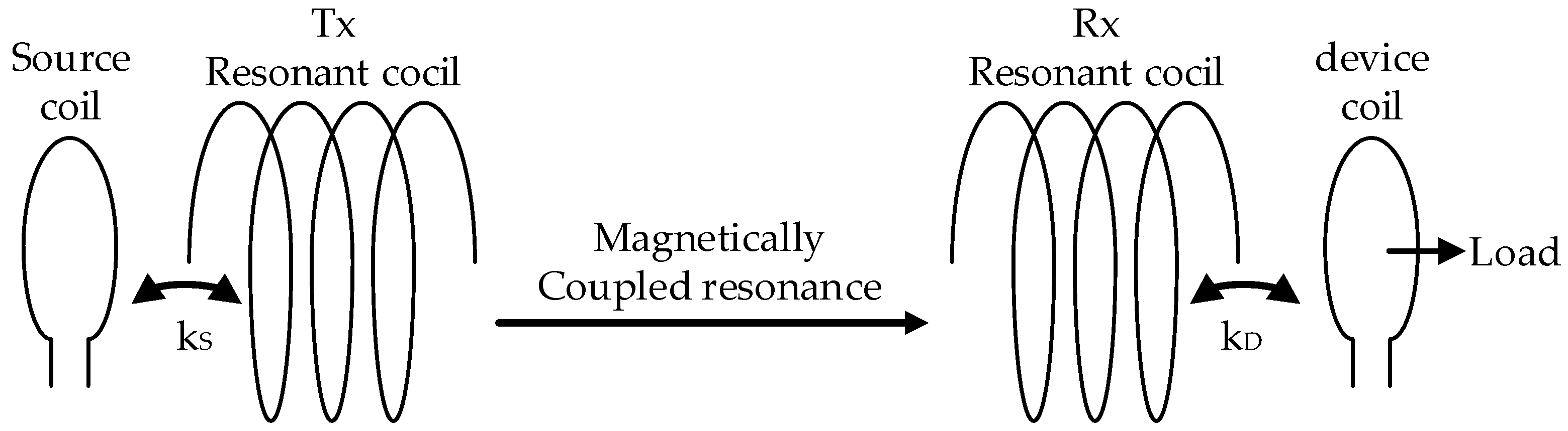
1.1. Wireless Power Transfer Method

Wireless power transmission is a technology that transfers electrical energy from power to load without using wires. Research is being conducted on various wireless power transmission technologies using RF signals, lasers, and sound waves. Wireless power transmission technology uses magnetic fields and electromagnetic fields, and magnetic induction and magnetic resonance methods [3] are classified. The magnetic inductive wireless power transmission system is widely used in small, low-power electronic devices, such as smartphones, after technical standardization and commercialization. In fields that require high-power transmission, such as digital home appliances and electric vehicles, research using magnetic resonance methods is being actively conducted.
As shown in Figure 1, magnetic induction [4] charges the battery by generating an induced current in two adjacent coils within a few mm. The receiving coil uses the principle of electromagnetic induction, which induces electricity under the influence of a magnetic field. It is harmless to the human body and standardized, so many applied products are sold. It can be applied to low-power small devices and is more than 90% efficient compared to power. Still, the distance between the charger and the receiver is very short, generating much heat. If the center of the transmitting and receiving coils does not exactly match, the efficiency decreases rapidly.
As shown in Figure 2, magnetic resonance method is advantageous for transmitting distance using each coil’s resonant and energy transmission frequencies. Still, the size of each coil must be larger than the magnetic induction method to secure high Q [5]. This magnetic resonance method can be applied to various fields compared to the magnetic induction method. Resonance is a state in which capacitors and inductors exchange energy and store energy, and the impedance changes significantly near the resonance frequency, and is widely used in band-pass filters, band-removal filters, and oscillation circuits.
The purpose of using a resonant converter is to achieve high efficiency, compactness, and weight reduction of the system, while improving switching losses from semiconductor devices in a typical PWM-type power conversion circuit. Soft switching technology can improve the switching loss of semiconductor devices for power in resonance converters. The principle of soft switching is ZVS [6,7], which operates when the current and voltage of a semiconductor device are zero voltage, and ZCS [8], which is used when the switch current is zero current. Each can be implemented as a resonant circuit, called a resonant tank, consisting of an inductor L and a capacitor C. This wireless power transmission method is a technology using magnetic fields that can affect the human body. Research has been conducted on guidelines [9] for the amount and time of exposure to the human body, and other studies are steadily underway to minimize the impact on humans [10,11].

1.2. Wireless Power Transmission System for Electric Vehicles

Wireless power transfer (WPT) is a promising technology currently being researched and developed in various fields, with electric vehicle (EV) wireless charging being a critical application [12]. Figure 3 is a configuration diagram of a wireless power transmission system for an electric vehicle. Conventional WPT systems for EVs typically use two-coil configurations, and research efforts are underway to develop more efficient configurations consisting of two to four coils, which have shown efficiency levels from 90 to 95%. However, a significant challenge in WPT-based EV charging is maintaining spatial charging freedom, as precise alignment between the transmitting and receiving coils is required for high-efficiency power transmission, which can be obstructed by the vehicle’s parking position or posture. To address this problem, we present a simulation study that evaluates the magnetic field strength of a WPT system, using a boost coil to improve efficiency. Additionally, we designed and constructed a circuit using a full-bridge converter topology and a resonant magnetic induction topology suitable for high-power WPTs at the kW level to investigate the impact of coil alignment on power transfer efficiency and spatial degrees of freedom. To improve the coupling coefficient of the coils, ferrite cores were placed in the transmission and reception coils. Our experimental results were obtained using a widely used circular coil in WPT, and they demonstrate the potential of the proposed approach to overcome the challenges associated with WPT-based EV charging.

2. Materials and Methods

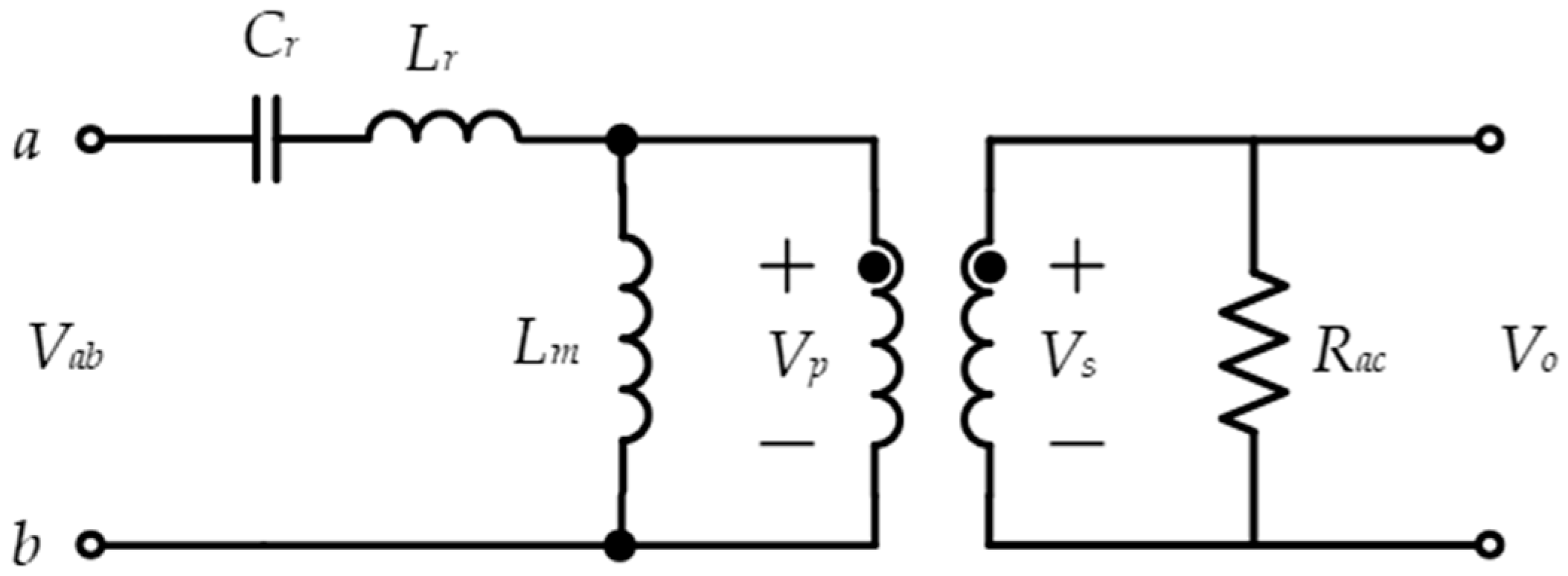
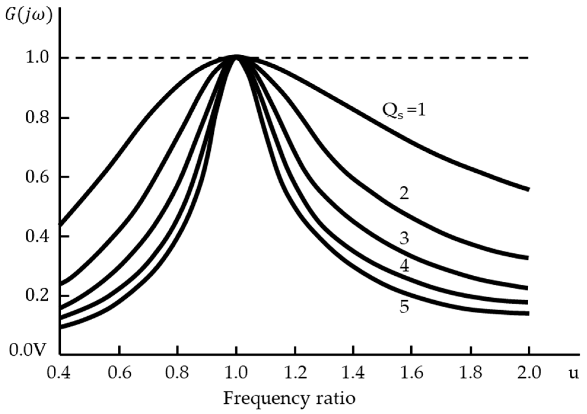
2.1. Series Resonant Converters

Figure 4 illustrates a series resonant circuit (SRC). The series resonant tank consists of a resonant inverter L r and a resonant capacitor C r , and the current flowing through the resonant tank is transferred to the secondary side through a transformer. To simplify the circuit, only a resistor is used as the load. When interpreting the frequency response of the RLC AC equivalent circuit, the input and output voltages exhibit a relationship, as expressed in Equation (1).
V G a i n = V o   V a b = R 1 + j   w o L s R a c     w w o w o w    
The resonant frequency f o of the resonant circuit is expressed in Equation (2) based on the resonant inductor L r and the resonant capacitor C r . The switching frequency response characteristics are interpreted in Equation (3), and the voltage gain characteristics according to the resonant frequency can be defined as plotted in Figure 5.
f o = 1 2 π L r C r  
Q = w o L r R L  
Generally, in resonant converters, the switching frequency f s of the power semiconductor devices is set higher than the resonant frequency f r of the resonant circuit, and the power semiconductor devices are always operated with zero-voltage switching (ZVS) to improve the efficiency of the converter. In the SRC, the output voltage can be controlled using the frequency ratio between f s and f r ; as the frequency ratio approaches 1, the output increases, and vice versa. Therefore, the switching frequency of the power semiconductor devices can be varied to control the converter output. However, under no-load or light-load conditions, the output cannot be controlled, and the following challenge exists: the input impedance of the resonant circuit becomes extremely low under a load short-circuit condition. Moreover, as the resonant circuit and the load are connected in series, almost no current flows through the resonant circuit under no-load conditions. Therefore, the converter yields an extremely high efficiency under no-load conditions.

2.2. Full-Bridge Series Resonant Converter

Full-bridge converters are power electronic circuits widely used in DC-to-DC power conversion, voltage regulation, and energy storage systems. They are applied to various applications, such as electric vehicles, renewable energy systems, and industrial power supplies. Control of the full-bridge converter is essential to regulate the output voltage, current, and power transmission efficiency. The choice of control strategies depends on the specific requirements of the application.
Linear control techniques, such as PI and PID controllers [13], are widely used for the control of the full-bridge converter due to their simplicity, ease of implementation, and robustness. Linear control is suitable for applications in which the dynamics of a system can be approximated by a linear model, and the performance requirements are moderate. PI and PID controllers use feedback from the output voltage and current to adjust the duty cycle of the switching devices to achieve the desired output regulation. Linear control techniques are effective in regulating the output voltage and current and maintaining the stability of the system.
Nonlinear control techniques [14], such as sliding mode control (SMC) [15] and model predictive control (MPC) [16], are required for high-performance applications in which the system exhibits complex dynamics, such as the presence of nonlinear loads or time-varying disturbances. Nonlinear control provides robust and efficient management by using system models and optimizing control tasks to achieve the desired performance. SMC is based on the sliding mode principle and controls the output voltage and current by regulating the sliding surface. MPC uses a model of the full-bridge converter [17] to predict the future behavior of the system and optimize the control actions to achieve the desired performance.
Figure 6 represents the entire circuit of the full-bridge series resonant converter [18]. The circuit consists of four switching devices ( Q 1 ,   Q 2 ,   Q 3 ,   Q 4 ), a high-frequency transformer, a series-connected resonant inductor, and a capacitor. The secondary side of the transformer comprises a rectifying diode and an output voltage filter.
Except for the fact that the resonant circuit composed of R L A C , L r , and C r is serially connected, the circuit structure is identical to that of a typical full-bridge DC-DC converter [19,20,21], wherein the R L on the secondary side of the transformer is converted to the primary side. The waveform changes according to the resonant frequency and the switching frequency, which are plotted in Figure 7, showing the voltage and current waveforms of each part according to the magnitude of the switching frequency and the resonant frequency.
Generally, the inductance and capacitance of the primary and secondary coils for resonance in WPT are defined according to Equation (4).
L p C p L s C s
The equivalent circuit is represented in Figure 8, on which each parameter is defined.
Given that Equation (4) holds true, the resonant angular frequency w r and the resonant frequency f r can be defined as expressed in Equations (5) and (6), respectively.
w r = 1 L p C p = 1 L s   C s  
f r = w r 2 π  
The full-bridge inverter generates a sine wave voltage between V d c and V d c with a duty cycle of 50%. In addition, the nominal operating frequency f o is kept fixed. Considering the standardization trend of the International Automobile Technology Association, the operating frequency f o for electric vehicle wireless charging systems is fixed at 85 kHz, which lies within the internationally available operating frequency band (81.38 kHz–90.00 kHz) [7]. Under the assumption that the full-bridge inverter operates at a fixed frequency, the WPT system is defined as expressed in Equations (7)–(10).
V p t = R p i p t + L p   d i p t d t + 1 C p   0 t i p τ d τ + M p s   d i s t d t  
v s t = M p s   d i p t d t + R s i s t + L s   d i s t d t + 1 C s   0 t i s τ d τ
v s t = R a c i s t
R a c = 8 π 2   R o
Assuming the initial values to be zero, the equations can be transformed into Equations (11) and (12) through Laplace transformation.
V p s = R p + s L p + 1 s C p   I p s + s M p s I s s
V s s = s M p s I p s + R s + s L s + 1 s C s   I s s
If R p and R s are set to 0, as they are infinitesimal values within the system, the voltage equation can be simplified, and V p and V s can be defined as shown in Equations (13) and (14), respectively.
V p s = s L p + 1 s C p     I p s + s   M p s   I s s
V s = s M p s I p s + s L s + 1 s C s   I s s
To prevent a spike in the voltage ratio at the resonant frequency in wireless power transmission, the frequency range from 81.38 to 90.00 kHz [22] is proposed as an essential strategy. Therefore, when designing, the voltage ratio should be considered according to the load. Considering the coupling coefficient k p s between the primary and secondary coils, the resonant frequency and mutual inductance M p s can be defined as presented in Equations (15) and (16), respectively.
w = 1 1 k p s L p C p  
M p s = k p s L p L s
Considering the k ps , the operating frequency f o can be expressed as presented in Equation (17).
f o = 1 2 π 1 k p s L p C p )  

2.3. Circuit Design Specifications and Prototype

Table 1 provides an overview of the experimental conditions used in this study, including input and output voltages set at DC 400 V, maximum output capacity designed at 3.3 kW, and operating frequency at 85 kHz [22].
Figure 9 shows the coils manufactured in this study. The transmission coils are both 800 mm in diameter, and the distance between the coils is 150 mm. In addition, eight ferrite cores were placed in each coil, improving the coupling coefficient between coils. The manufactured coil is a commonly used coil system designed to check the efficiency that changes according to the alignment of the coils.
Table 2 shows the design specifications of the experimental wireless power transfer system.
Figure 10 depicts the power conversion module, which is a key component of the wireless power transmission system. The module is composed of two main components: the primary-side transmission module and the secondary-side receiver module.
The primary-side transmission module is responsible for converting the input power into a form that is suitable for wireless transmission. This is achieved using a full-bridge converter circuit, which is a type of circuit that converts a DC input voltage into a variable AC voltage. The full-bridge converter circuit is connected to the power source and provides the necessary voltage and current regulation to the wireless power transmission system. Additionally, the primary-side transmission module also includes overcurrent and overvoltage protection circuits to prevent damage to the system in case of power surges or other anomalies. Finally, a controller circuit is included to ensure that the power transmission is conducted efficiently and safely.
On the other hand, the secondary-side receiver module is responsible for converting the wireless power signal back into usable electrical energy. This is accomplished using a rectifier circuit that uses diodes to convert the AC signal received from the wireless transmission into a DC signal. A DC capacitor is also included in the secondary-side receiver module to smooth out any voltage fluctuations and ensure a stable output voltage.

2.4. Modeling of Coils for Simulation

2.4.1. Modeling of the Circular Two-Coil System

One of the main challenges of wireless power transmission systems is the efficiency of power transmission, which can be affected by several factors, including coil alignment. Various strategies have been proposed to solve this problem, including using different coil sizes on the primary and secondary sides.
In a circular two-coil system, the primary coil is designed to be wider than the secondary coil. This design helps minimize transmission efficiency degradation when coils are misaligned. In addition, eight ferrite cores were placed in each coil to improve the coupling coefficient, while also improving the magnetic coupling between coils and increasing power transfer efficiency. The design of wireless power transmission systems includes various factors, such as efficiency, size, and compatibility with multiple devices. By carefully considering these factors, you can create a system that can provide reliable and efficient power transmission in demanding environments or conditions.
Figure 11 and Figure 12 show the specifications of the circular 2-coil system, including the size and shape of the coils, the number of ferrite cores, and other parameters. The primary coil is designed to be wider than the secondary coil, minimizing the reduction in transmission efficiency due to poor coil alignment.

2.4.2. Modeling of Circular Five-Coil System

The 5-coil wireless power transmission system is a noteworthy design that aims to enhance power transmission efficiency and mitigate the effects of power losses during the wireless energy transfer process.
Figure 13 and Figure 14 illustrate the configuration of the 5-coil wireless power transmission system. The structure of this system is identical to the previously mentioned 2-coil system, except for the addition of three boost coils. Specifically, two boost coils were introduced on the transmitting side, and one boost coil was incorporated on the receiving side. The boost coils in this system play a critical role in increasing power transfer efficiency by providing additional energy to the system. These boost coils are carefully positioned to optimize the magnetic coupling between the primary and secondary coils, which enhances energy transfer efficiency.
Under the proposed wireless power transmission scenario, the coil structure of the transmission side is positioned above the ground level, while the receiving-side coil is installed beneath the bottom of the car. In line with the experimental setup, the distance between the two coils was set to a fixed value of 15 cm.

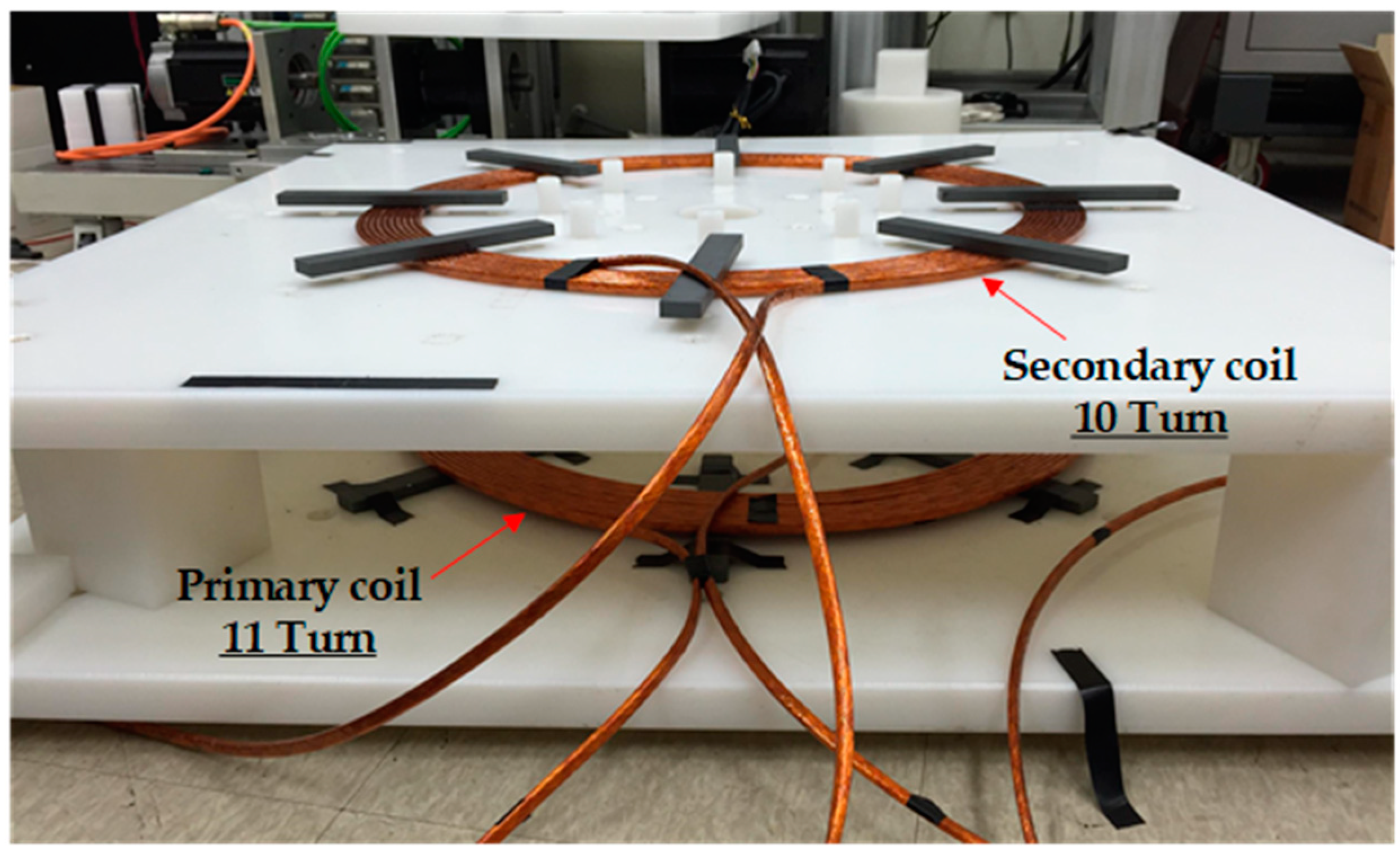
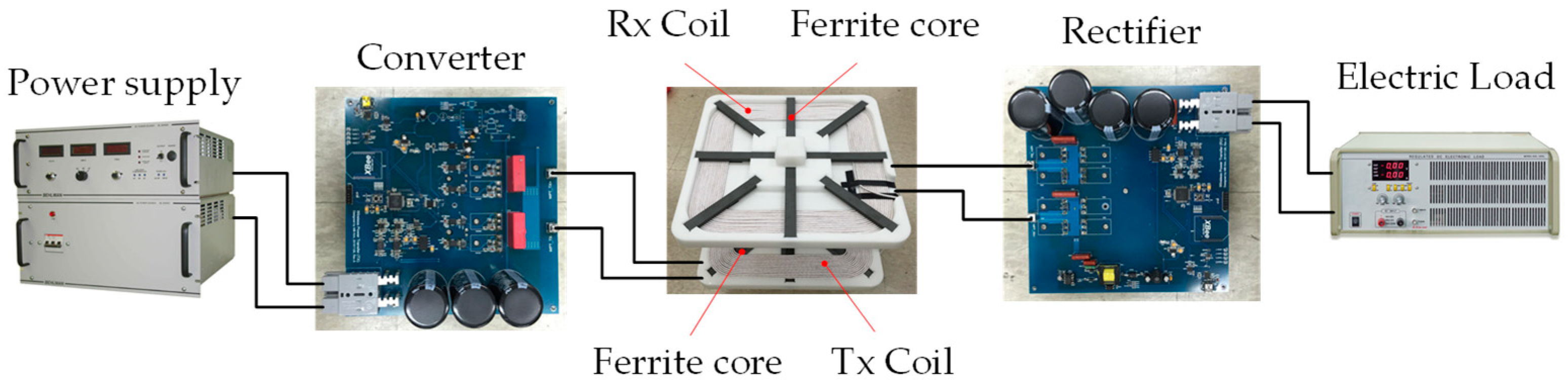
2.5. Configuration of Experimental System

The proposed experimental setup for wireless power transmission is visualized in Figure 15, which includes a power supply unit, a power transmission module (consisting of a transmitter module, coils, and receiver module), and an electric load. The primary transmitter unit in the power transmission module consists of a full-bridge converter circuit, overcurrent and overvoltage protection circuits, and a controller circuit. The secondary receiver unit comprises a diode-based rectifier circuit and a capacitor. To measure transmission efficiency, input/output voltage and current were measured using a digital multimeter for high power. An input source configured the input power of the system using a high-power DC power supply capable of supplying up to 15 kW, and a high voltage DC electric load with a capacity of 600 W–14.4 kW was used on the power terminal.

3. Results

3.1. Effect of Coil Alignment on Efficiency

Figure 16, Figure 17 and Figure 18 present the current waveforms on the primary and secondary coils of the circular two-coil system.
Table 3 and Figure 19 provide detailed measurements of the efficiency changes observed in the two-coil wireless power transmission system manufactured for this study. The results indicate that power transmission efficiency varies significantly depending on the load and alignment of the coils. Specifically, the efficiency decreases as the load decreases, and the highest efficiency of 92.9% was observed at the maximum output capacity of 3.3 kW.
The measurement results also reveal that the alignment of the coils significantly impacts the efficiency of power transmission. The maximum efficiency of 92.9% was achieved when the coils were well aligned, with the center of the receiving coil positioned near the center of the transmitting coil. When the center of the receiving coil was placed 10 cm away from the center of the transmitting coil, the efficiency only decreased slightly to 92.3%, indicating that the efficiency change was relatively insignificant. However, when the distance between the two coils was increased to 15 cm, the transmission efficiency decreased to 90.9%, and the efficiency dropped exponentially as the horizontal distance increased.
These findings highlight the importance of coil alignment in optimizing the efficiency of wireless power transmission systems and suggest that even minor deviations in alignment can significantly impact power transfer efficiency.

3.2. Simulation

To investigate the effect of the amplification coil on the magnetic field, simulations were performed by comparing the two- and five-coil systems to the boost coil. The coil alignment was changed from 0 mm to 150 mm in increases of 50 mm to analyze the magnetic field strength. The simulation results for the magnetic field strength of each system are analyzed and presented in Figure 20 and Figure 21. The purpose of this analysis is to examine the effect of coil alignment on the performance of wireless power transmission systems. These simulation results illustrate the advantages of the five-coil system, including improved magnetic field strength and the smooth flow of magnetic fields from the transmission coil to the reception coil.
Figure 20 shows that the magnetic field intensity graph of the five-coil system with boost coils is more potent than that of the two-coil system. When the coil centers are aligned, the magnetic field intensity of the two-coil system is close to zero due to the difference in coil diameters, indicating no coupling between the coils. Except for when the coils are aligned, both systems generate magnetic fields up to a horizontal separation distance of 150 mm. However, it was confirmed that the magnetic field intensity of the five-coil system with boost coils is more potent than that of the two-coil system. In particular, it was observed that the effect of the boost coil is most significant at a separation distance of 100 mm.
As shown in Figure 21, these amplification coils can significantly improve the magnetic field strength and increase the area affected by the magnetic field. This, in turn, can lead to more efficient power transfer and a better response to coil misalignment. In particular, the difference between the two-coil system and the five-coil system shows that the flow of magnetic fields from the transmitting coil to the receiving coil is smoother with the five-coil system, especially when the receiving coil is 100 mm off the center of the transmitting coil.
These findings are significant because they suggest that the five-coil system is well suited for wireless power transmission systems for electric vehicles. With the increasing popularity of electric vehicles, there is a growing need for efficient and reliable wireless power transmission systems to keep vehicles on the road. Using amplification coils in a five-coil system represents a promising approach to meeting this need and ensuring that electric vehicles can be charged quickly and efficiently, even in less-than-ideal coil alignment scenarios.

4. Discussion

In this study, to confirm and improve the efficiency change according to the alignment of the coils of the wireless power transmission system, a five-coil system with a booster coil was designed, and its potential effectiveness was investigated through simulation.
A full-bridge serial resonance converter was designed and manufactured to investigate the effect of alignment on the efficiency of a two-coil wireless charging system. The results showed that the initial efficiency of 92.929% was achieved when the coils were perfectly aligned. A minor decrease in efficiency to 92.252% was observed when the center of the receiving coil was shifted horizontally by 10 cm from the center of the transmitting coil. However, a significant drop in efficiency was observed as the horizontal separation distance increased to 15 cm. To address this issue, a coil system was designed to minimize the efficiency change when the center of the receiving coil was 150 mm away from the center of the transmitting coil, which is within the allowable deviation range of a parked car in a standard 2.3 m wide parking lot.
A two-boost-coil transmitting system and a single-boost-coil receiving system were designed and implemented, adding eight ferrite cores per coil to improve the coupling coefficient. To further improve the system’s flexibility, the transmitting coil was designed to be approximately 1.8 times larger than the receiving coil. Simulation analyses were conducted to verify the effectiveness of the design, including a comparison between the two-coil and five-coil systems.
In conclusion, the effectiveness of the proposed five-coil system, incorporating boost coils and changes in coil shape, was confirmed through experiments and simulation analyses. Compared to the two-coil system, the magnetic field strength of the five-coil system was observed to increase, providing greater power transmission capacity and distance. The use of boost coils is expected to be particularly beneficial for wireless charging systems for electric vehicles, improving efficiency, even in cases of coil misalignment, and potentially reducing system costs. Future research should focus on developing compensation techniques that can maintain stable transmission efficiency within the design range, even in cases of coil misalignment. Overall, the findings of this study contribute to the advancement of wireless power transfer technology and its potential applications in various industries.

Author Contributions

Conceptualization, Y.-K.C.; data curation, Y.-K.C.; formal analysis, D.-J.L.; methodology, Y.-K.C.; validation, D.-J.L. and Y.-K.C.; supervision, S.-J.P.; visualization, Y.-K.C.; writing—original draft preparation, Y.-K.C.; writing—review and editing, S.-J.P. All authors have read and agreed to the published version of the manuscript.

Funding

This research received no external funding.

Data Availability Statement

Not applicable.

Conflicts of Interest

The authors declare no conflict of interest.

References

  1. Global Passenger Electric Vehicle Market Share, Q1 2021—Q4 2022. Available online: https://www.counterpointresearch.com/ko/global-electric-vehicle-market-share/ (accessed on 9 March 2023).
  2. New SAE Wireless Charging Standard is EV Game-Changer. Available online: https://www.sae.org/news/2020/10/new-sae-wireless-charging-standard-is-ev-game-changer (accessed on 23 March 2023).
  3. Yousuf, M.A.; Das, T.K.; Khallil, M.E.; Aziz NA, A.; Rana, M.J.; Hossain, S. Comparison Study of Inductive Coupling and Magnetic Resonant Coupling Method for Wireless Power Transmission of Electric Vehicles. In Proceedings of the 2021 2nd International Conference on Robotics, Electrical and Signal Processing Techniques (ICREST), DHAKA, Bangladesh, 5–7 January 2021. [Google Scholar]
  4. Yiming, Z.; Shuxin, C.; Xin, L.; Yi, T. Design of high-power static wireless power transfer via magnetic induction: An overview. CPSS Trans. Power Electron. Appl. 2021, 6, 4. [Google Scholar]
  5. Park, J.-H.; Park, B.-C.; Lee, J.-H.; Ryu, Y.-H.; Park, E.-S.; Kwon, S.-W. Optimum frequency of high Q-factor resonator for magnetic resonance coupling. In Proceedings of the 2011 41st European Microwave Conference, Manchester, UK, 15 December 2011. [Google Scholar]
  6. Liu, K.-H.; Lee, F. Zero-voltage switching technique in DC/DC converters. IEEE Trans. Power Electron. 1990, 5, 293–304. [Google Scholar] [CrossRef]
  7. Chen, W.; Lee, F.C.; Jovanović, M.M.; Sabate, J.A. A Comparative Study of a Class of Full Bridge Zero-Voltage-Switched PWM Converters. In Proceedings of the IEEE APEC’95 Conference, Dallas, TX, USA, 5–9 March 1995; Volume 2, pp. 893–899. [Google Scholar]
  8. Pahlevaninezhad, M.; Das, P.; Drobnik, J.; Jain, P.K.; Bakhshai, A. A Novel ZVZCS Full-Bridge DC/DC Converter Used for Electric Vehicles. IEEE Trans. Power Electron. 2012, 27, 2752–2769. [Google Scholar] [CrossRef]
  9. McRobbie, D. Guidelines for limiting exposure to time-varying electric and magnetic fields (1 Hz to 100 kHz). Health Phys. 2011, 100, 442. [Google Scholar] [CrossRef] [PubMed]
  10. Douglas, M.G.; Roman, J.M.; Cooper, E.B.; Sample, A.P.; Waters, B.H.; Smith, J.R.; Kuster, N. Evaluation of Wireless Resonant Power Transfer Systems With Human Electromagnetic Exposure Limits. IEEE Trans. Electromagn. Compat. 2013, 55, 2. [Google Scholar]
  11. El-Shahat, A.; Danjuma, J.; Abdelaziz, A.Y.; Aleem, S.H.E.A. Human Exposure Influence Analysis for Wireless Electric Vehicle Battery Charging. Clean Technol. 2022, 4, 785–805. [Google Scholar] [CrossRef]
  12. Triviño, A.; González-González, J.; Aguado, J. Wireless Power Transfer Technologies Applied to Electric Vehicles: A Review. Energies 2021, 14, 1547. [Google Scholar] [CrossRef]
  13. Sun, H.; Liu, C.; Zhang, H.; Cheng, Y.; Qu, Y. Research on a Self-Coupling PID Control Strategy for a ZVS Phase-Shift Full-Bridge Converter. Math. Probl. Eng. 2021, 2021, 6670382. [Google Scholar] [CrossRef]
  14. Fortuna, L.; Buscarino, A. Nonlinear Technologies in Advanced Power Systems: Analysis and Control. Energies 2022, 15, 5167. [Google Scholar] [CrossRef]
  15. Young, K.D.; Utkin, V.I.; Umit, O. A Control Engineer’s Guide to Sliding Mode Control. IEEE Trans. Control. Syst. Technol. 1999, 7, 3. [Google Scholar] [CrossRef] [Green Version]
  16. Rawlings, J. Tutorial overview of model predictive control. IEEE Control Syst. 2000, 20, 38–52. [Google Scholar]
  17. Xie, Y.; Ghaemi, R.; Sun, J.; Freudenberg, J.S. Model Predictive Control for a Full Bridge DC/DC Converter. IEEE Trans. Control. Syst. Technol. 2012, 20, 164–172. [Google Scholar]
  18. Jeong, G.-Y.; Kwon, S.-H.; Park, G.-Y. Simple High Efficiency Full-Bridge DC-DC Converter using a Series Resonant Capacitor. J. Electr. Eng. Technol. 2016, 11, 100–108. [Google Scholar] [CrossRef] [Green Version]
  19. Mortazavizadeh, S.A.; Palazzo, S.; Amendola, A.; De Santis, E.; Di Ruzza, D.; Panariello, G.; Sanseverino, A.; Velardi, F.; Busatto, G. High Frequency, High Efficiency, and High Power Density GaN-Based LLC Resonant Converter: State-of-the-Art and Perspectives. Appl. Sci. 2021, 11, 11350. [Google Scholar] [CrossRef]
  20. Wang, P.; Cui, G.; Chen, L. Analysis and design of LLC with new current driven synchronous rectifiers. In Proceedings of the 2011 International Conference on Electrical and Control Engineering, Yichang, China, 16–18 September 2011; pp. 4344–4347. Available online: https://ieeexplore.ieee.org/document/6057321/metrics#metrics (accessed on 20 September 2022).
  21. Wu, S.-T.; Han, C.-H. Design and Implementation of a Full-Bridge LLC Converter with Wireless Power Transfer for Dual Mode Output Load. IEEE Access 2021, 9, 120392–120406. [Google Scholar] [CrossRef]
  22. SAE International: ‘Agreement on Frequency of Operation and Power Classes for Wireless Power Transfer for Its Electric and Plug-In Electric Vehicle Guideline’. 2015. Available online: http://www.sae.org/ (accessed on 20 September 2022).
Figure 1. Inductive wireless power transfer system.
Energies 16 03213 g001
Figure 2. Wireless power transmission system of an electric vehicle.
Energies 16 03213 g002
Figure 3. Wireless power transmission system of an electric vehicle.
Energies 16 03213 g003
Figure 4. Series resonant circuit.
Energies 16 03213 g004
Figure 5. Voltage gain and frequency response characteristics of a series resonant converter.
Energies 16 03213 g005
Figure 6. Full-bridge series resonant converter.
Energies 16 03213 g006
Figure 7. Voltage and current waveform according to switch on/off.
Energies 16 03213 g007
Figure 8. Equivalent circuit of wireless power transfer system.
Energies 16 03213 g008
Figure 9. Coils built for power transmission.
Energies 16 03213 g009
Figure 10. Prototype of the full-bridge series resonant converter. (a) Transmission module; (b) receiver module.
Energies 16 03213 g010
Figure 11. Two-coil system specifications and configurations. (a) Rx coil; (b) Tx coil.
Energies 16 03213 g011
Figure 12. Two-coil system modeling.
Energies 16 03213 g012
Figure 13. Receiver coil on the secondary side. (a) Rx coil; (b) Tx coil.
Energies 16 03213 g013
Figure 14. Five-coil system modeling.
Energies 16 03213 g014
Figure 15. Configuration of the experimental system.
Energies 16 03213 g015
Figure 16. Current waveforms of primary and secondary coils of the 2-coil system (horizontal separation distance is 0 cm).
Energies 16 03213 g016
Figure 17. Current waveforms of primary and secondary coils of the 2-coil system (horizontal separation distance is 10 cm).
Energies 16 03213 g017
Figure 18. Current waveforms of primary and secondary coils of the 2-coil system (horizontal separation distance is 15 cm).
Energies 16 03213 g018
Figure 19. Efficiency with respect to the coil separation distance.
Energies 16 03213 g019
Figure 20. Strength (RMS) of magnetic field according to coil axis separation distance.
Energies 16 03213 g020
Figure 21. Magnetic field strength of the coil system.
Energies 16 03213 g021aEnergies 16 03213 g021b
Table 1. Experimental conditions of wireless power transmission system.
Input voltage (Vdc)DC 400 V
Output voltage (Vo)DC 400 V
Output power (Po)3.3 k W
Operating frequency (fo)85 kHz
Table 2. Design specifications of the wireless power transfer system for the experiment.
V i n 400 V M p s 49.25 uH
V O U T 400 V K p s 0.29
I o u t 8.25 A L l k p 136.18 uH
N p 3300 W L l k s 102.31 uH
L p 193 uH L m 56.82 uH
L s 145 uH F o 85 kHz
L s h o r t 176 uH C p 20.30 nF
N p 11 Turn C S 27.02 nF
N s 10 Turn L r 173 uH
N 1 R a c 39.30
Table 3. Efficiency data of circular 2-coil system.
Horizontal Distance
0 cm
Horizontal Distance
10 cm
Horizontal Distance
15 cm
Pout (W)Efficiency (%)Pout (W)Efficiency (%)Pout (W)Efficiency (%)
50167.050466.850966.4
104681.0101680.1106980.4
152586.2158486.1153584.9
202589.1202088.5211588.1
251890.9253790.4252889.4
303192.3301791.6307690.6
332592.9331092.3331490.9
Disclaimer/Publisher’s Note: The statements, opinions and data contained in all publications are solely those of the individual author(s) and contributor(s) and not of MDPI and/or the editor(s). MDPI and/or the editor(s) disclaim responsibility for any injury to people or property resulting from any ideas, methods, instructions or products referred to in the content.

