Article

Design and Analysis of the Inlet Valve for the CFETR Torus Cryopump

1
Institute of Plasma Physics, Hefei Institutes of Physical Science, Chinese Academy of Sciences, Hefei 230031, China
2
Graduate School, University of Science and Technology of China, Hefei 230026, China
*
Author to whom correspondence should be addressed.
Energies 2023, 16(7), 3107; https://doi.org/10.3390/en16073107
Submission received: 16 February 2023 / Revised: 13 March 2023 / Accepted: 16 March 2023 / Published: 29 March 2023
(This article belongs to the Section B4: Nuclear Energy)

Abstract

:
The China Fusion Engineering Test Reactor (CFETR), a superconducting magnetic confinement tokamak fusion reactor, will develop a high-performance torus cryopump to pump torus plasma exhaust gas. The inlet valve is one of the key components of the cryopump, and it is used to isolate the cryopump from the plasma for regeneration, to control the pumping speed of the cryopump, and to operate as a pressure relief valve in case of a failure, such as the cryopipe breaking inside the cryopump chamber. This paper presents a novel inlet valve. Ensuring that the design of the inlet valve meets the above requirements will be a challenge. In order to verify the reliability of the inlet valve, its critical components are analyzed and optimized by the Finite Element Method. The effect of the stroke of the inlet valve on pumping performance is then estimated by the Monte Carlo Method, and the pressure profile in the whole flow field is studied to predict the cryopump’s behavior. Finally, the seismic capacity of the optimized inlet valve is analyzed, and the mechanical performance of the inlet valve is shown to meet CFETR design criteria. These design and analysis results will provide technical support and references for the development of the CFETR torus cryopump.

1. Introduction

Fusion energy, which is a viable and sustainable energy source, has become a research hotspot regarding nuclear power. Magnetic confinement fusion is one of the most promising ways to achieve controlled thermonuclear fusion, and its feasibility has been preliminarily verified. The China Fusion Engineering Test Reactor (CFETR) is a superconducting magnetic confinement tokamak fusion reactor, which is used to generate self-sufficient fusion energy and address the gaps between the experimental reactor and the Demonstration Power Plant (DEMO) [1,2]. The missions of the CFETR are to demonstrate steady-state burning plasmas and produce a fusion power of ≥1 GW; the fusion energy gain factor (Q), which is the ratio of fusion power produced in a fusion reactor to the power required to maintain the plasma in a steady state, Q > 10; the tritium breeding ratio (TBR), which is the ratio of the rate of tritium produced in a fusion reactor to the rate of tritium burned in plasma, TBR > 1; and a neutron dose requirement of 50 dpa (displacements per atom) [3,4]. To attain these goals, it is necessary to carry out a long pulse plasma discharge, which poses a severe challenge to the CFETR torus vacuum vessel pumping system. A cryopump has significant advantages, such as high pumping speed, non-pollution, and a simple structure, and is generally considered to be the main form of the torus vacuum pump of the future fusion reactor [5].
The development of high-performance cryopumps is a burgeoning area of research around the world. Y. Li et al. [6] evaluated the behavior of an HL-2M in-vessel cryopump with the Monte Carlo method. The results showed that the pumping performance was strongly influenced by the conductance of the divertor. H.J. Lee et al. [7] demonstrated the in-vessel cryopump of the Korea Superconducting Tokamak Advanced Research (KSTAR) for particle control. The structural analysis on the cryopump was performed by ANSYS. S. Mukherjee et al. [8] studied the pumping speed of a liquid nitrogen-cooled cryopump by Molflow+ for different sticking co-efficient values and the influence of different geometric conditions on the nitrogen pumping speed. Ranjana Gangradey et al. [9] developed a test cryopump applied to Steady-state Superconducting Tokamak-1 (SST-1). They estimated the heat load on the liquid nitrogen bath and the structural loads on the base plate with six supports by ANSYS. M. Kovari et al. [10] predicted the pumping performance of a compound cryopump in the transition regime with the Monte Carlo Method. The results indicated that the behavior of the pump can be accurately simulated.
The current commercial cryopump cannot meet the requirements of the torus vacuum vessel pumping system, such as pumping speed and capacity, neutron shielding, installation space, and operation and maintenance, so it is urgent to design a suitable cryopump for the pumping system. A novel high-performance torus cryopump (TCP) used for CFETR is designed by Chinese Academy of Sciences (ASIPP). The sub-components of the cryopump can be primarily divided into the inlet valve, the pump casing with the main flanges, the cryogenic circuits including the charcoal coated cryopanel assembly, and the thermal radiation shield assembly. The design of the pumping system is based on nine identical TCPs that are located on direct extensions of the lower ports of the vacuum vessel [11], as shown in Figure 1. TCP is used to pump hydrogen isotopes, helium ash, and impurity gases produced by plasma burning through the divertor slots to regenerate fusion fuel, and to provide high vacuum pumping during other operation phases, including evacuation during dwell periods between plasma discharges, wall conditioning, bakeout, and leak testing [12]. Therefore, an integral inlet valve is designed to fulfil the operation requirements of the TCP. The inlet valve should have the following functions:
(1)
It isolates the cryopump from the plasma for regeneration by closing the inlet valve;
(2)
It controls the pumping speed of the cryopump by adjusting the inlet valve opening;
(3)
It operates as a pressure relief valve in case of a failure, such as the cryopipe breaking inside the cryopump chamber.
This paper will describe the design principles and the structural design, analysis, and assessment for the inlet valve in detail. The results will provide a theoretical basis for the design of a CFETR torus cryopump.

2. Structure Design of the Inlet Valve

The space and geometry requirements on the installation must be taken into account when the inlet valve is designed. The inlet valve is composed of a valve disc, a valve shaft, and a pneumatic actuator assembly. An overview of the inlet valve is represented in Figure 2.

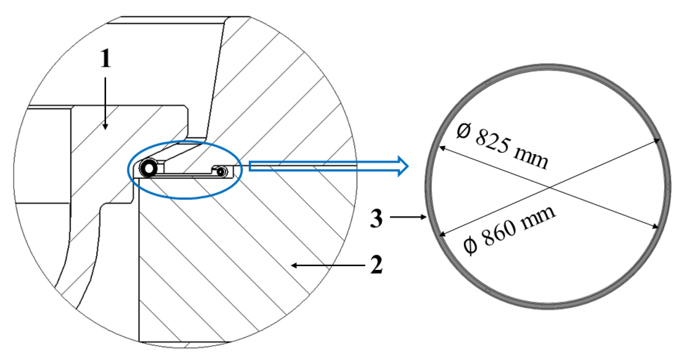
2.1. Valve Disc with Its Sealing Part
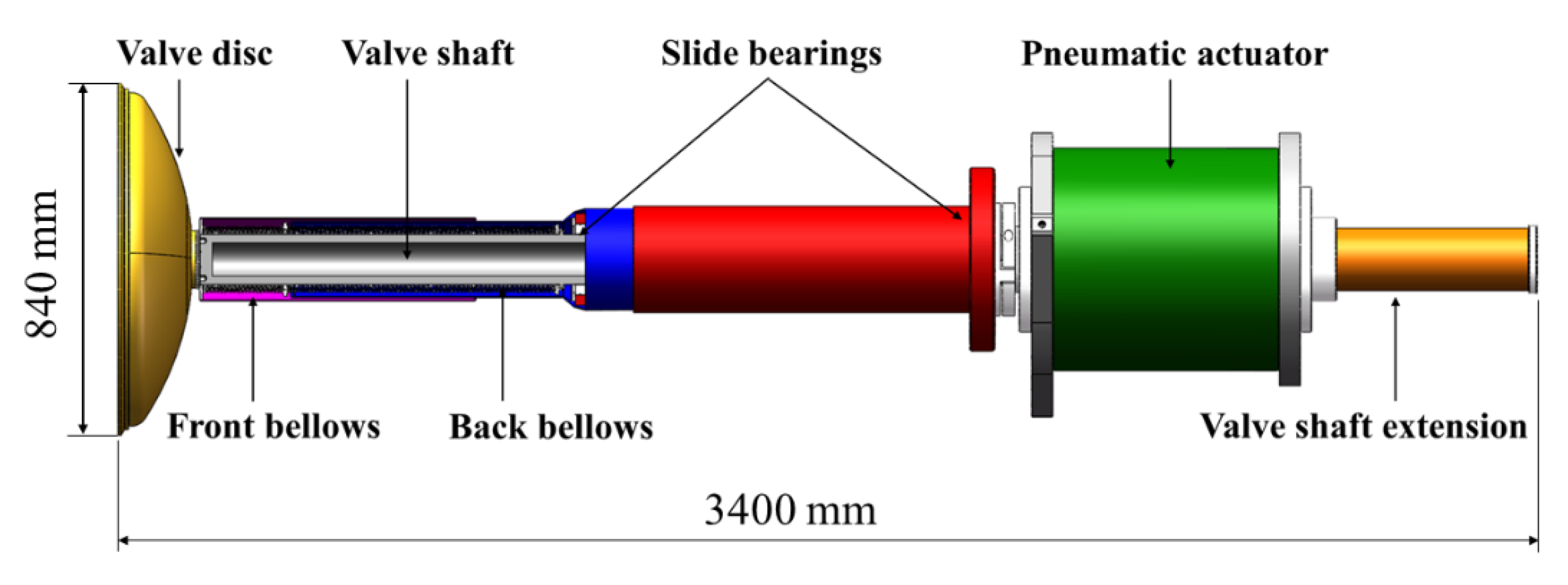
In order to isolate the cryopump from the vacuum vessel for regeneration, the seal at the pump inlet has to meet the leakage requirements of 10−4 Pa·m3/s at 5 kPa and 10−3 Pa·m3/s at 100 kPa inside the cryopump [13]. The structure of the seal ring affects the sealing performance between the valve disc and the front flange. With the wide range of requirements, a spring-loaded metal double seal ring mounted onto the front flange, including static and dynamic seals, is used. A schematic diagram of the seal at the pump inlet is shown in Figure 3.
Its high sealing force is only provided by the valve disc itself, so it is necessary to design a suitable valve disc and evaluate its structural strength. Combined with the requirements of a high-performance cryopump and previous testing, the diameter of a valve disc made of austenitic stainless steel SS316L is required to be at least 840 mm and the height of it set to 178 mm. Although the diameter and height of the valve disc are determined, the performance of it can be varied with different types and thicknesses. In order to study the effect of the shape of the valve disc on structural stress and deformation, four types of valve discs are designed. In Figure 4, (a) is a rectangular valve disc, (b) is a fillet valve disc, (c) is a stepped valve disc, and (d) is a disc-shaped valve disc. The structural analysis of the valve disc will be discussed in Section 4.1 to find the optimal design scheme.

2.2. Valve Shaft

The valve shaft is fixed on the valve disc using bolts for mechanical attachment and supported by two slide bearings which are operated in a controlled atmosphere to avoid high wear due to a lack of lubricant for reciprocation. Since the valve shaft needs long-stroke reciprocating movement, the bellows should be able to work under the conditions of variable loads, large displacement, and a large number of cycles [14]. The bellows assembly is composed of two edge-welded metal bellows, V-shaped, in a series connection that is used for the valve shaft sealing and displacement compensation.
To avoid the impact of the temperature change of the valve disc on the pumping performance of the cryopump, a high-temperature nitrogen channel used to control the temperature of the valve disc at about 300 K is installed in the center of the valve shaft [15]. Considering the space limitation, the inner diameter of the valve shaft is set to 80 mm, and the outer diameter of it does not exceed 140 mm. The structure of the valve shaft directly affects the deformation of the valve disc, and its excessive deformation can lead to the sealing failure of the inlet valve. Therefore, the bending deflection of the valve shafts with different thicknesses is calculated in Section 4.2.

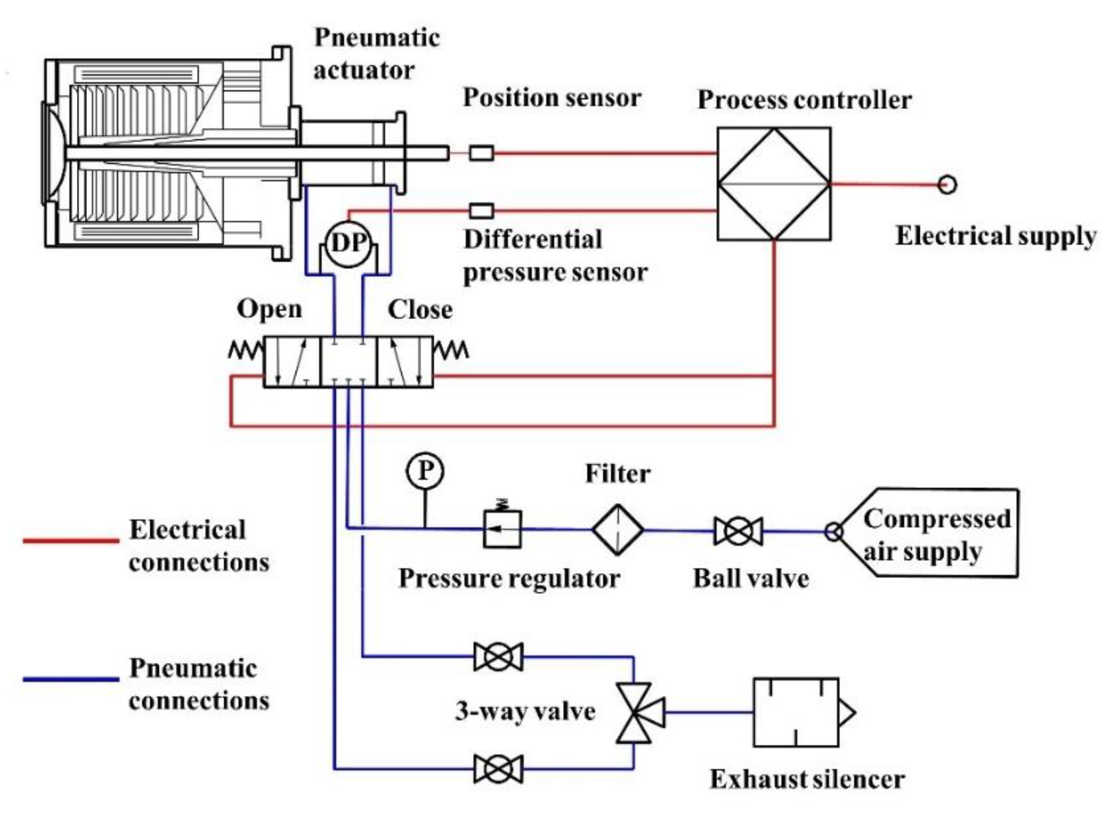
2.3. Pneumatic Actuator

The position of the inlet valve is controlled by the pneumatic actuator. As a result, a double-acting pneumatic actuator and a control system that is used to control and monitor the position of the pneumatic actuator within a limited time are developed. The actuator should fulfill the following requirements. Figure 5 shows the diagram of the valve actuator control circuit.
(1)
The actuator shall interlock with the inlet valve so that one is allowed to open with any significant pressure rise within the pump chamber;
(2)
It provides the power that moves the inlet valve back and force to regulate the inlet flow between 0 and 100%;
(3)
The maximum time for complete opening or closure is no more than 10 s;
(4)
The inlet valve can be moved with an accuracy of 1 mm;
(5)
It limits the exhaust noise of the actuator to acceptable level ≤ 75 dB;
(6)
For the operation at CFETR, about 30,000 cycles without maintenance are expected.

3. Simulation Methods

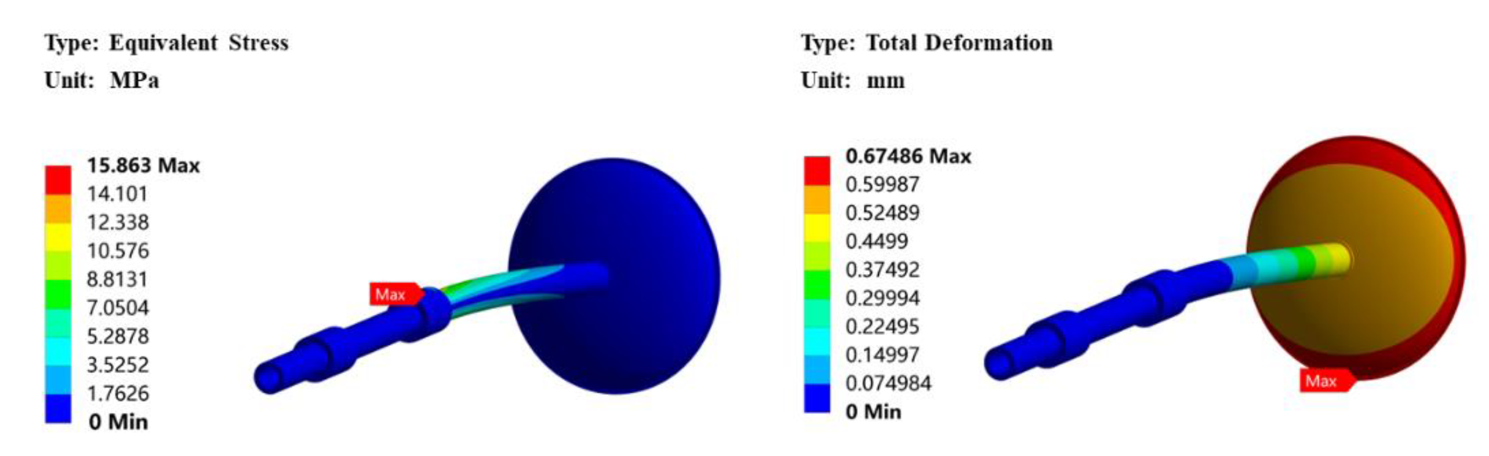
3.1. Mechanical Analysis of the Inlet Valve

When the cryopump is in the regeneration stage, the pump inlet needs to be sealed with the inlet valve. The effect of the shape and thickness of the valve disc on its mechanical performance was estimated by ANSYS.
When the cryopump is in the pumping stage, the inlet valve is moved to open the pump inlet. In order to make the bending deflection of the inlet valve meet the design criteria, the structure of the valve shaft needs to be optimized.
The theoretical basis for the mechanical analysis of the inlet valve is the dynamic balance equation:
[ M ] u + [ C ] u + [ K ] { u } = { F ( t ) }
Here, [ M ] is the mass matrix; [ C ] is the damping matrix; [ K ] is the stiffness matrix; u is the acceleration vector; u is the velocity vector; { u } is the displacement vector; { F ( t ) } is the force vector.

3.2. Estimation of the Transmission Probability

3.2.1. Design Target Function

The probability of collision between gas molecules and the inlet valve determines the pumping capacity of the cryogenic pump to a large extent; therefore, the structure of the inlet valve plays an essential role in the pumping performance of the cryopump. Based on the TCP operating environment and requirements, the effect of the stroke of the inlet valve on pumping speed is explored.
The basic design equation for calculating the actual pumping speed Sa is shown in Equation (2) [16].
S a = c S t = c A R T / ( 2 π M )
where Sa and St denote the actual pumping speed and the theoretical black hole pumping speed, m3/s; c denotes the capture coefficient; A denotes the inlet cross-section, m2; R denotes the gas constant; T denotes temperature, K; and M denotes mass of the gas being pumped, g/mol.
The capture coefficient which depends on the structure of the cryopump and the interaction of pumped gas with cryogenic adsorption surfaces is expressed as:
1 c =   1 w + 1 P s 1
Here, w denotes the total transmission probability and Ps denotes the sticking probability.
In order to carry out a sound and balanced design for the inlet valve and study the parameters affecting the performance of the cryopump, a numerical analysis shall be performed with the Monte Carlo Method for the gas flow through the vacuum duct into the cryopump. Compared with theoretical calculation, numerical analysis is more suitable for calculating the transmission probability of complex geometries [17,18].

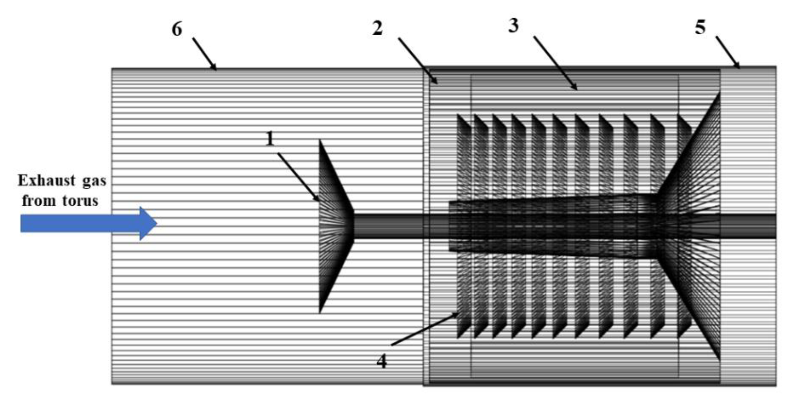
3.2.2. Physical Model

The physical model of the cryopump is simplified to reduce the computational complexity, and the model is as shown in Figure 6. The vacuum duct represents a cylinder with a diameter of 1.5 m and a length of 1.5 m. During the pumping phase of the cryopump, exhaust gas with a constant throughput flows to the pump through the vacuum duct. The gas molecules will interact with other molecules and walls until they are trapped on the cryogenic surfaces of the pump [19].

3.2.3. Gas Flow Model

Gas flow regime in the vacuum duct and cryopump is mainly molecular flow, so the gas flow model is simplified as follows.
Newton’s laws of motion are used to calculate particle trajectories.
d d t m d q d t = 0
The particle velocity is given by:
v = d q d t
Particles scatter according to Knudsen’s law.
v x = c sin θ
v y = c cos θ
c” is sampled from the following function:
ρ ( c ) = 2 π m k B T 3 / 2 c 2 exp m c 2 2 k B T
where c is the particle speed, θ is the angle between the particle velocity and the wall normal, the subscript x is the tangential component of the velocity and y is the normal, ρ ( c ) is the probability density, and k B is the Boltzmann constant.

3.3. Boundary Conditions and Settings

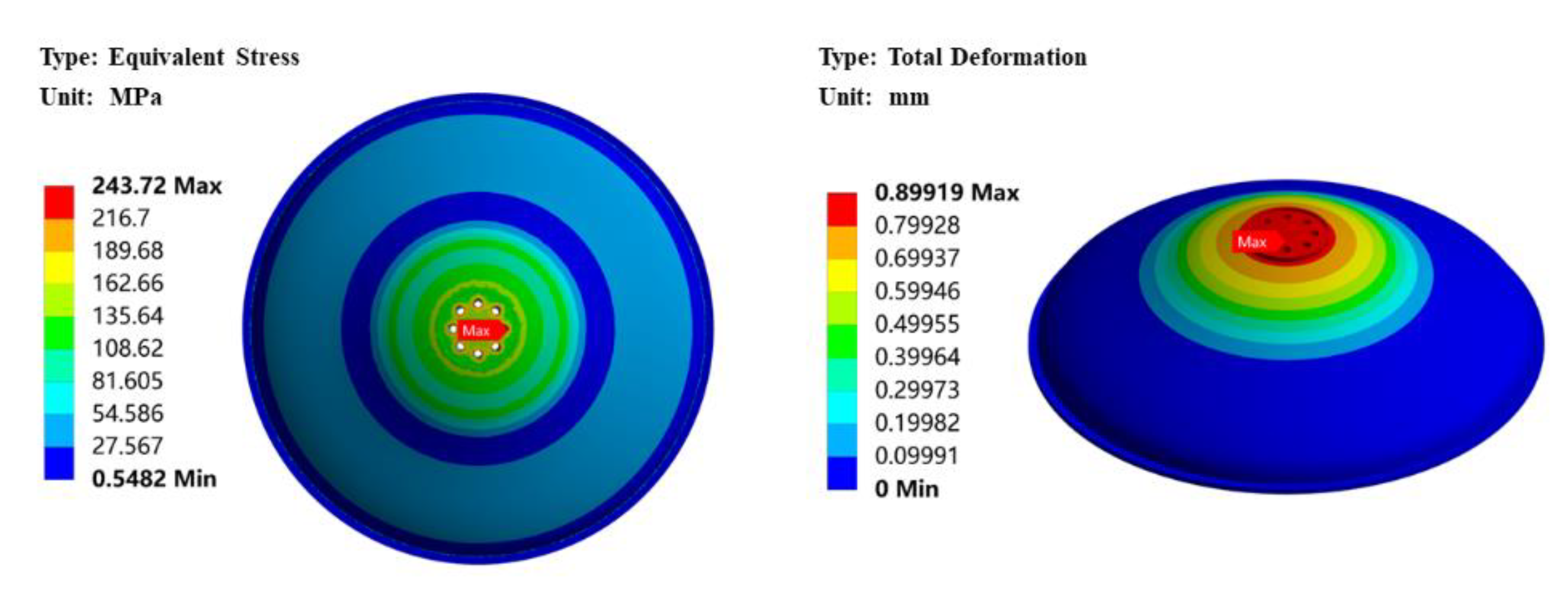
3.3.1. Mechanical Analysis of the Valve Disc

The main settings are as follows:
(1)
The sealing surface of the valve disc is set as fixed support, and the contact surface between the valve disc and the valve shaft is set as force surface;
(2)
The sealing force is 150 kN;

3.3.2. Mechanical Analysis of Valve Shaft

The main settings are as follows:
(1)
The surfaces of the slide bearings are set as fixed support;
(2)
The contact type between the valve shaft and the bearing is set to friction, and the friction coefficient is 0.01;
(3)
Gravity.

3.3.3. Estimation of the Transmission Probability

During the pumping phase of the cryopump, deuterium (D2), the representative gas of the exhaust gas, is selected as the research object [20]. The simulated settings are as follows:
(1)
The expression of transmission probability;
The transmission probability describes the number of D2 molecules adsorbed on the cryogenic surface divided by the number of D2 molecules from the intake surface. The formula of transmission probability is expressed as:
W = lim N A N
Here, W is the transmission probability, A is the number of D2 molecules adsorbed on the cryogenic surface, and N is the number of D2 molecules from the intake surface.
(2)
Temperature;
The temperature of the cryopanels is 4.5 K, the temperature of the thermal radiation shield and the louver baffle are 80 K, and the temperature of the injected gas is 300 K.
(3)
Gas throughput;
The gas throughput is 100 Pa·m3/s.
(4)
Sticking coefficient.
The value of the sticking coefficient for D2 is 0.8.

3.3.4. Seismic Analysis

The CFETR torus cryopump is classified as a key fortification device according to GB50011-2010 (Chinese standard). In order to study the seismic capacity of the inlet valve, a preliminary seismic analysis must be carried out. In this study, the seismic acceleration of Hefei, a city in China, is selected as the design input as shown in Table 1. It is required that all devices can be put into operation again without special maintenance and testing under the seismic load.
Dynamic balance equation of earthquake acceleration excitation is expressed as:
u ( t ) + 2 ω n ζ u ( t ) + ω n 2 u ( t ) = u g ( t )
where
ω n = k m
ζ = c 2 m ω n
Relative displacement, u ( t ) , is given by:
u ( t ) = 1 ω n 1 ζ 2 0 t u g ( τ ) e ω n ζ ( t τ ) sin ω n 1 ζ 2 ( t τ ) d τ
Here, u ( t ) , u ( t ) , and u ( t ) are the relative displacement, velocity, and acceleration of the particle to the ground; u g ( t ) is the acceleration of ground motion; ω n is natural frequency; k is the seismic horizontal influence coefficient; m is the particle mass; ζ is the critical damping ratio; c is damping.

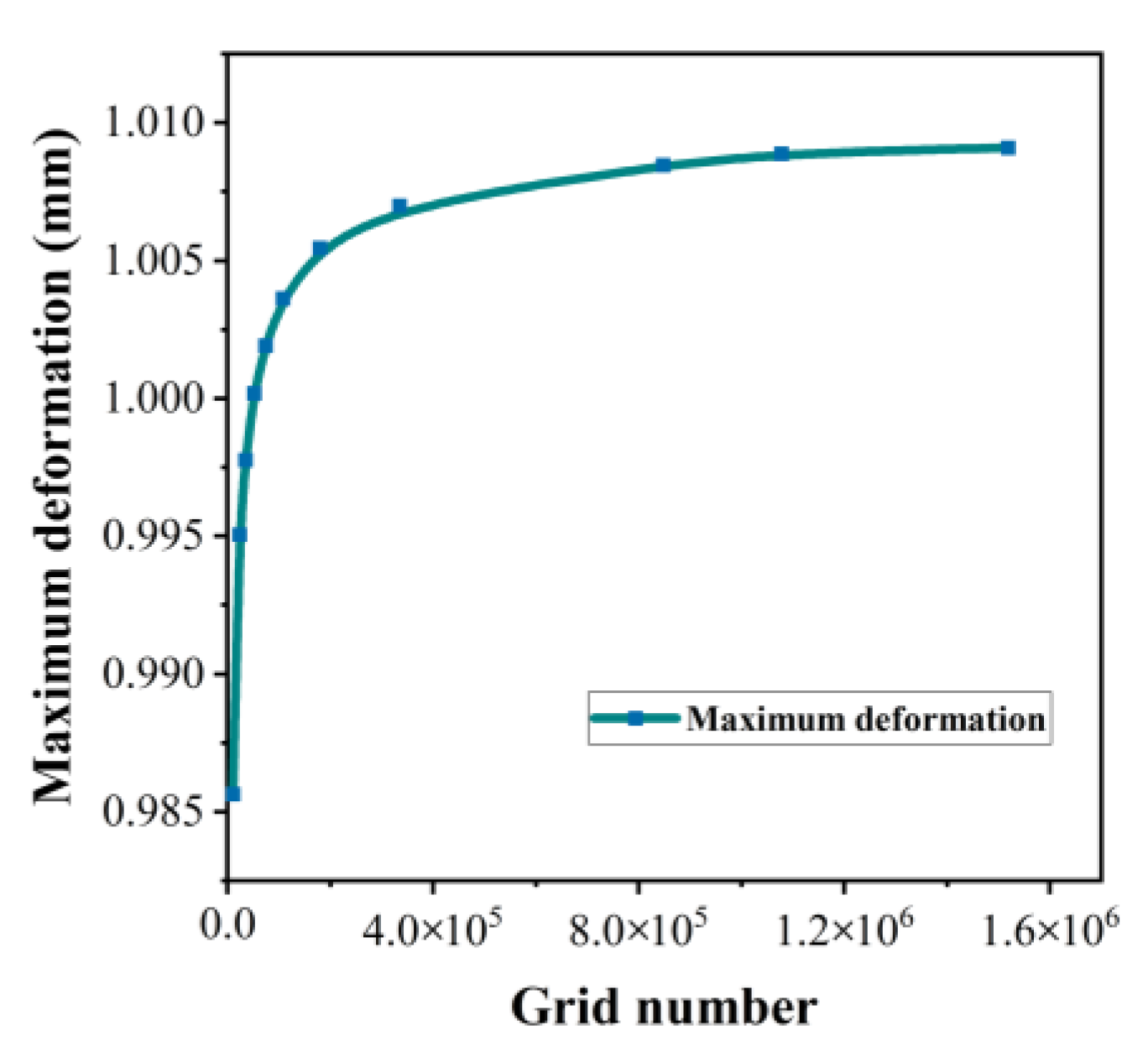
3.4. Grid Independence Investigation

The grid independence was carried out. Figure 7 shows that the maximum deformations of the valve disc are calculated with different grid numbers under the same boundary conditions. It is seen that the simulation results are hardly affected when the grid number exceeds 800,000. Therefore, a grid model with 857,538 cells was used for calculations.

3.5. Validity of Calculation by Monte Carlo Method Investigation

Since the transmission probability of the inlet valve is studied with the Monte Carlo (MC) Method, it is necessary to investigate the validity of the MC calculation. A tube is selected as the research object, with one end as the adsorption face and the other end as the desorption face. Under the same boundary conditions, the transmission probabilities of tubes with different length (L) and radius (R) ratios are calculated with the MC Method and Clausing integral equation [21,22], respectively.
The Clausing integral equation for a tube can be expressed as:
w ( x ) = w 0 ( x ) + 0 L K ( x , x ) w ( x ) d x
where
w 0 ( x ) = 1 2 ( x 2 + 2 x 2 + 4 x )
K ( x , x ) = 1 2 1 x x 6 + ( x x ) 2 4 + ( x x ) 2 1.5
The transmission probability, W, can be determined by Equation (17).
W = 1 L 0 L ( x 2 + 2 x x 2 + 4 ) w ( x ) d x
Table 2 shows the comparison of the results calculated by the two methods. It can be seen that the relative errors are about 10−5, which verifies the rationality of using the MC method to calculate the transmission probability.

4. Result and Discussion

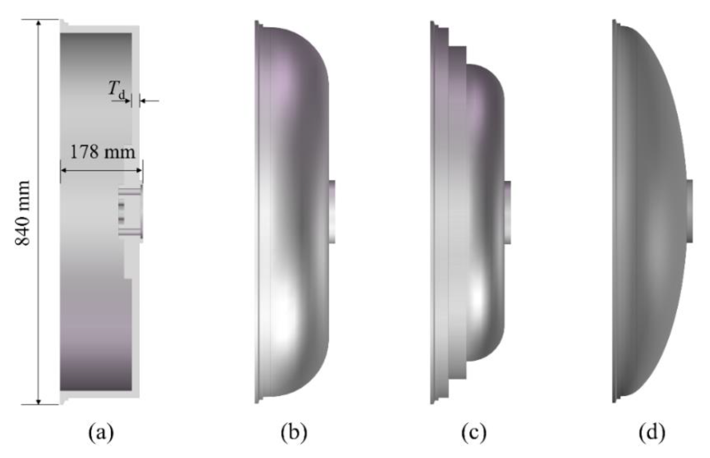
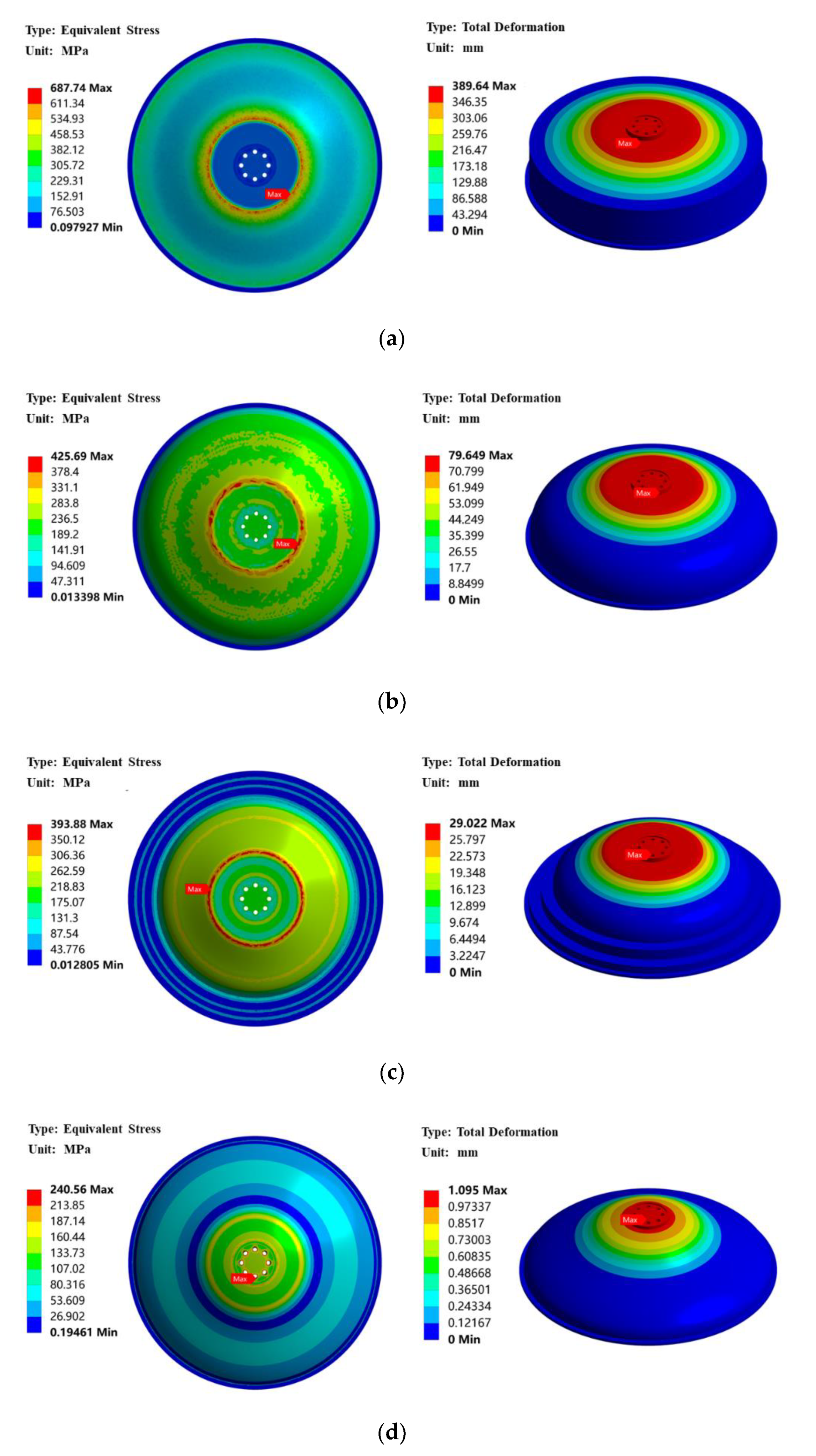
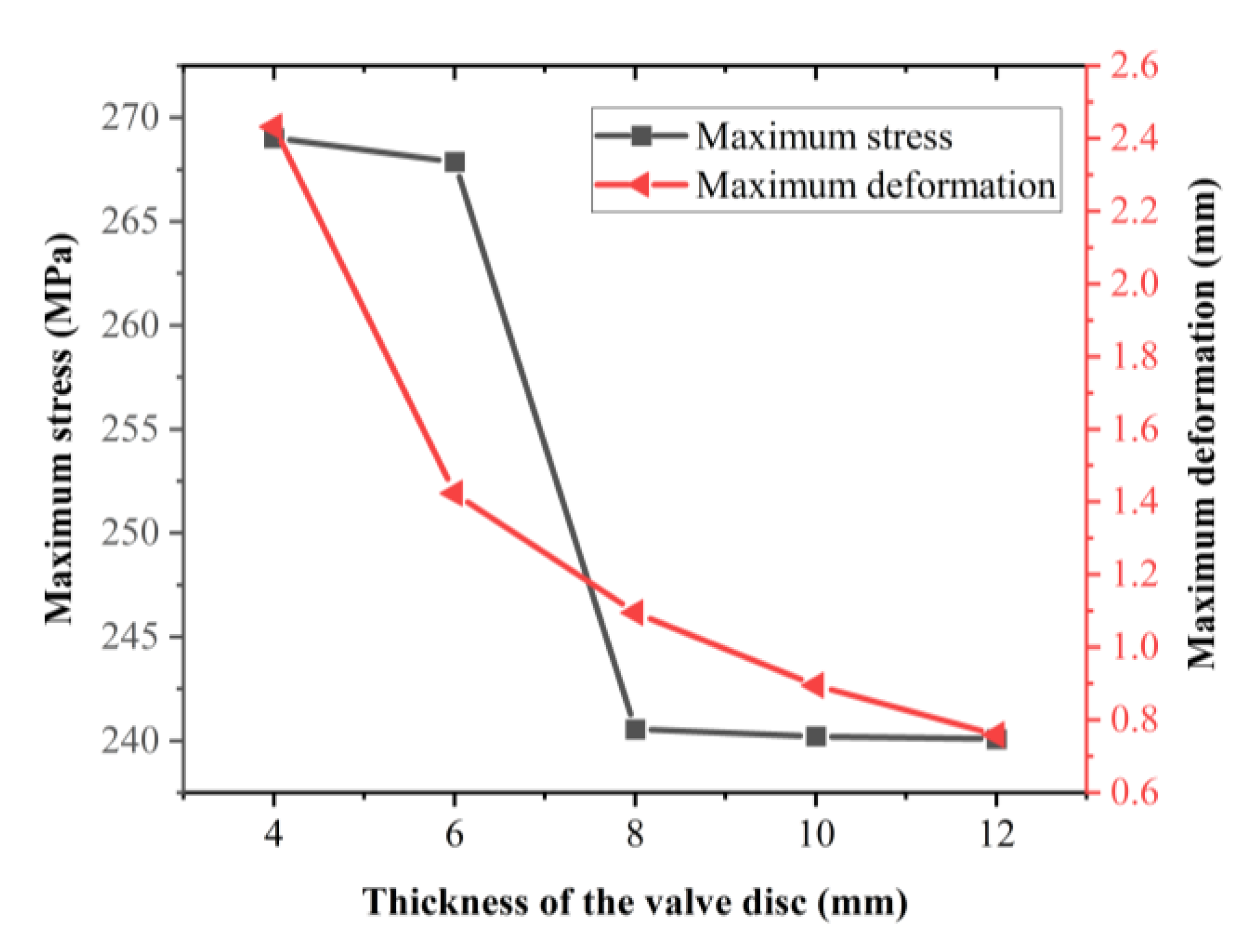
4.1. Finite Element Analysis and Assessment of Valve Discs

Figure 8 displays the stress and deformation distributions of four types of valve discs in the initial design, which is 840 mm in diameter, 178 mm in height, and 8 mm in thickness, under the sealing force. For the rectangular valve disc, the maximum stress is about 687.74 MPa located at the neck edge of the valve disc, and the maximum deformation is about 389.64 mm in the bottom edge of the valve disc. For the fillet valve disc, the maximum stress is about 425.69 MPa, and the maximum deformation is about 79.65 mm. For the stepped valve disc, the maximum stress is about 393.88 Mpa, and the maximum deformation is about 29.02 mm. For the disk-shaped valve disc, the maximum stress is about 240.56 Mpa located at the bolt opening at the bottom of the valve disc, and the maximum deformation is about 1.10 mm in the bottom edge of valve disc.
The valve material is SS316L with a tensile strength of 485 Mpa, according to National Standard criteria (GB/T 3280-2015). Under the sealing force, the rectangular valve disc (a) is severely deformed, and the maximum stress is far greater than the tensile strength of the material. In order to reduce the stress concentration of the rectangular valve disc, it is optimized into the fillet valve disc (b) and the stepped valve head (c). It can be seen that the maximum stress of the fillet valve disc and the stepped valve head is lower than the tensile strength of the material, but the deformation exceeds the range of design requirements. The type of the valve disc is further optimized into a disc-shaped valve disc (d), which shows that the mechanical performance of the disk-shaped valve disc has been significantly improved. The maximum stress of the disk-shaped valve disc is far lower than the tensile strength of the material, but the deformation exceeds the design requirement of less than 1.0 mm. Therefore, the effect of the thickness of the disk-shaped valve disc on its mechanical performance will be investigated below.
The thicknesses of the valve discs are chosen to be 4 mm, 6 mm, 8 mm, 10 mm, and 12 mm, respectively. Figure 9 shows the mechanical performance of the disk-shaped valve disc at different thicknesses. It is found that the maximum stress of the valve disc decreases significantly as the thickness of the valve disc increases from 4 mm to 8 mm. From 8 mm to 12 mm, the maximum stress of the valve disc is only slightly affected by the thickness. The maximum deformation of the valve disc gradually decreases with increasing thickness. When the thickness is 10 mm, the maximum deformation of the valve disc is about 0.89 mm, and the maximum stress is about 240.23 MPa. When the thickness is 12 mm, the maximum deformation of the valve disc is about 0.76 mm, and the maximum stress is about 240.08 MPa. Both design options meet the design requirements, but as the thickness of the valve disc increases, its mass will also increase, resulting in an increase in the bending deflection of the valve shaft. Therefore, the thickness of the valve disc is set to 10 mm. The above analysis results are shown in Table 3.

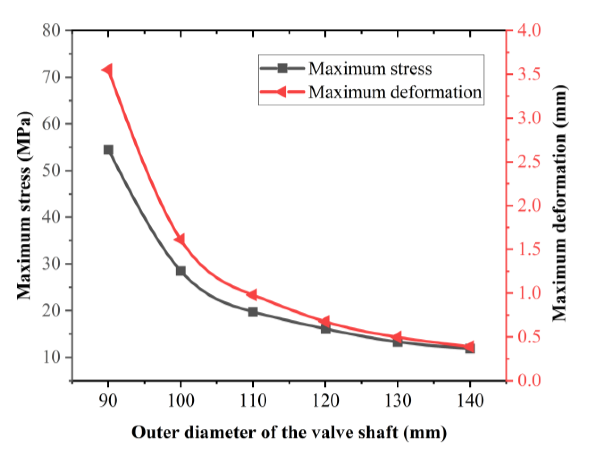
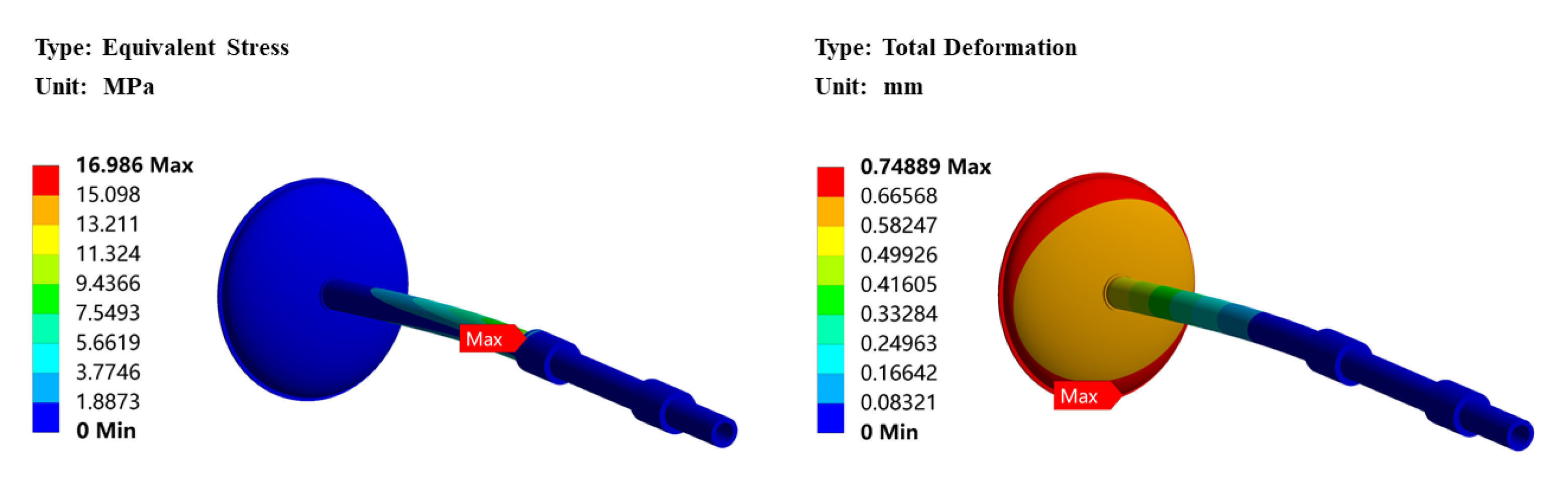
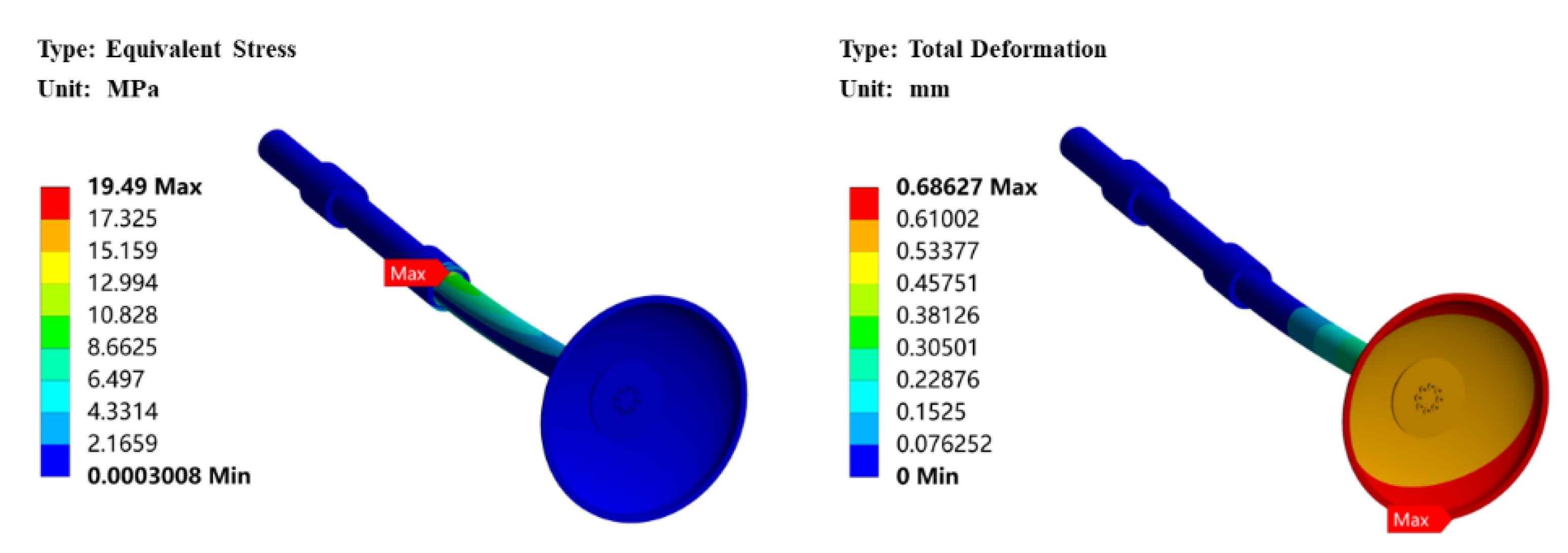
4.2. The Effect of Thickness of the Valve Shaft on Bending Deflection of the Inlet Valve

Figure 10 shows the maximum stress and deformation of the valve shaft at different outer diameters under the sealing force. It can be determined that the maximum stress and deformation of the valve shaft decrease with the increase in the outer diameter of the valve shaft. Except when the outer diameter is 90 mm and 100 mm, the deformation of the valve shaft in other design schemes all meet the design requirements, in which case, it is necessary to consider the effect of the wall thickness of the valve shaft on the bending deflection of the inlet valve under the gravity. As shown in Figure 11, when the outer diameter of the valve shaft is greater than 110 mm and the stroke is 450 mm, the maximum stress of the inlet valve does not exceed 20 MPa, which is below the allowable stress of the material. When the outer diameter of the valve shaft is not less than 120 mm, the maximum deformation of the inlet valve does not exceed 0.7 mm, meeting the torus cryopump design requirements. Considering the space limitation, the outer diameter of the valve shaft is set to 120 mm. Figure 12 shows the stress and deformation distributions of the inlet valve with the valve shaft outside diameter of 120 mm. The maximum stress occurs at the contact between the valve shaft and the front bearing, about 15.86 MPa, and the maximum deformation occurs at the outer edge of the valve disc, about 0.68 mm.

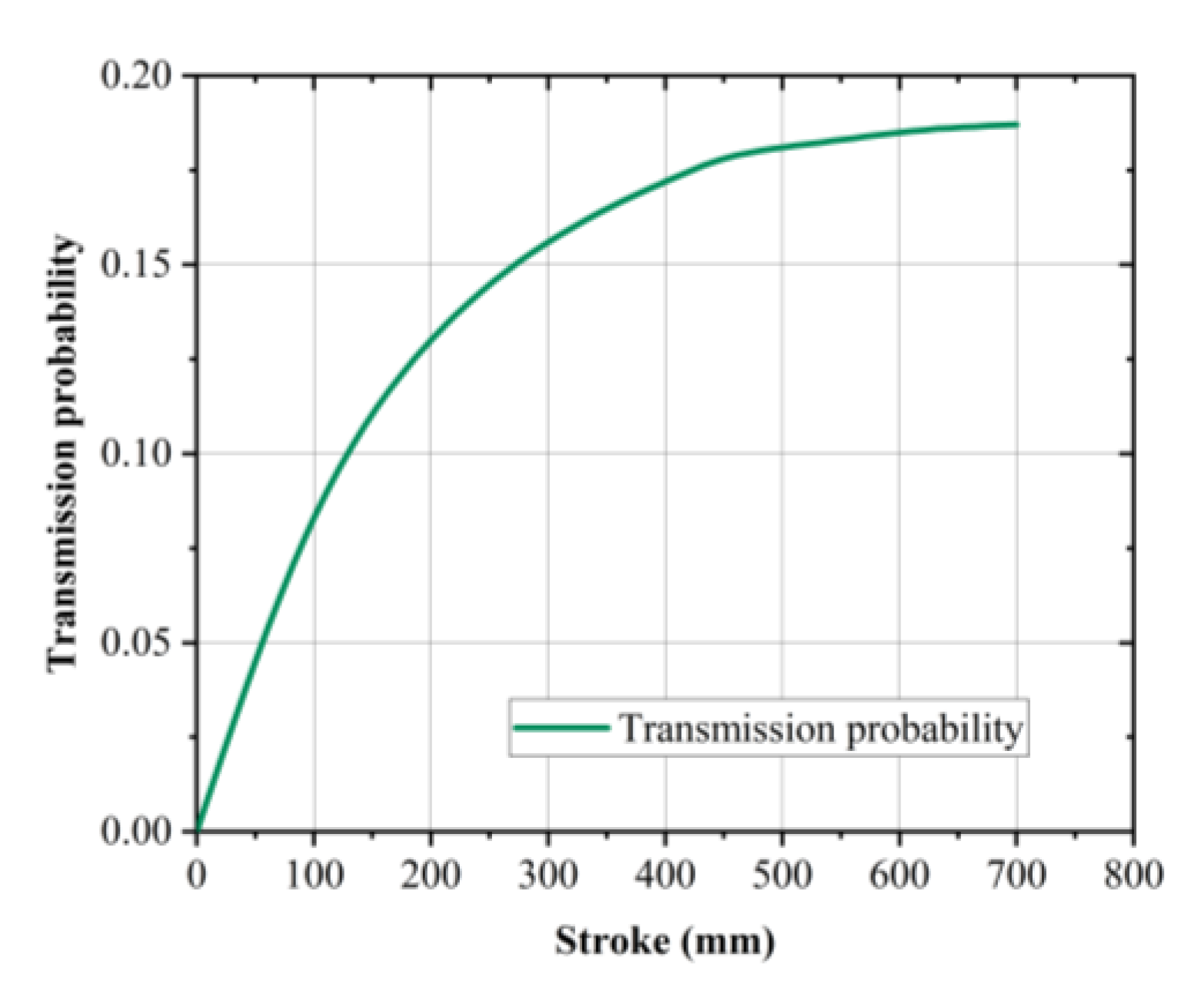
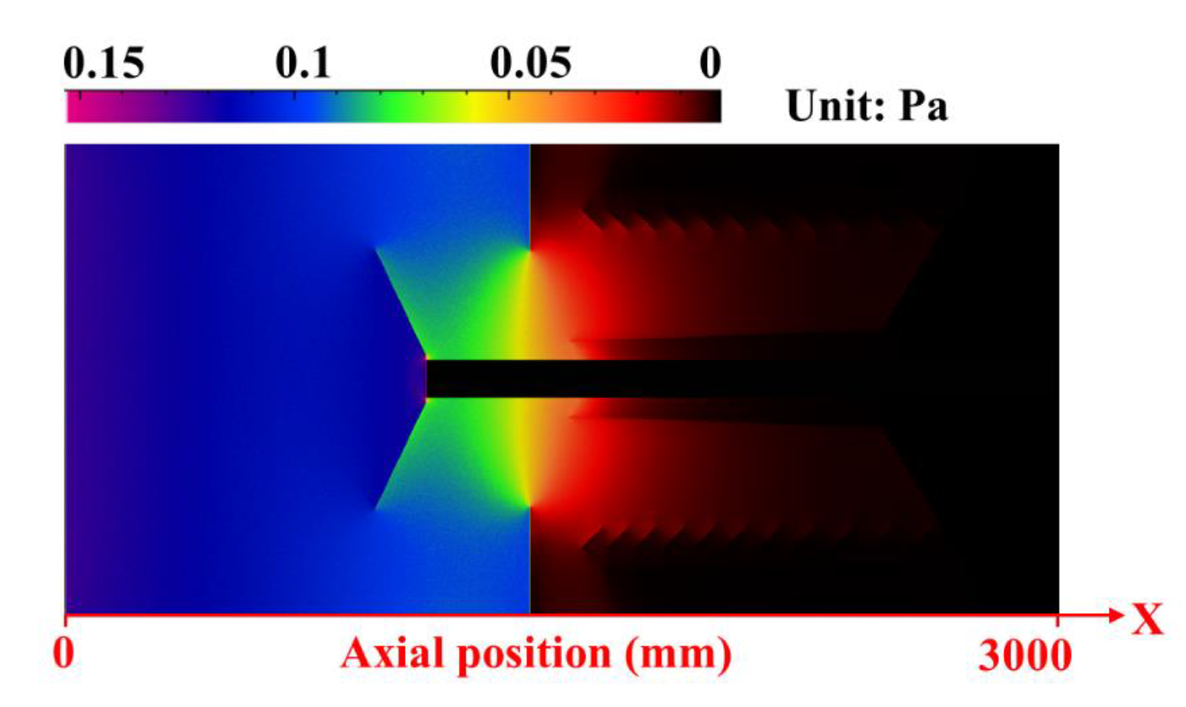
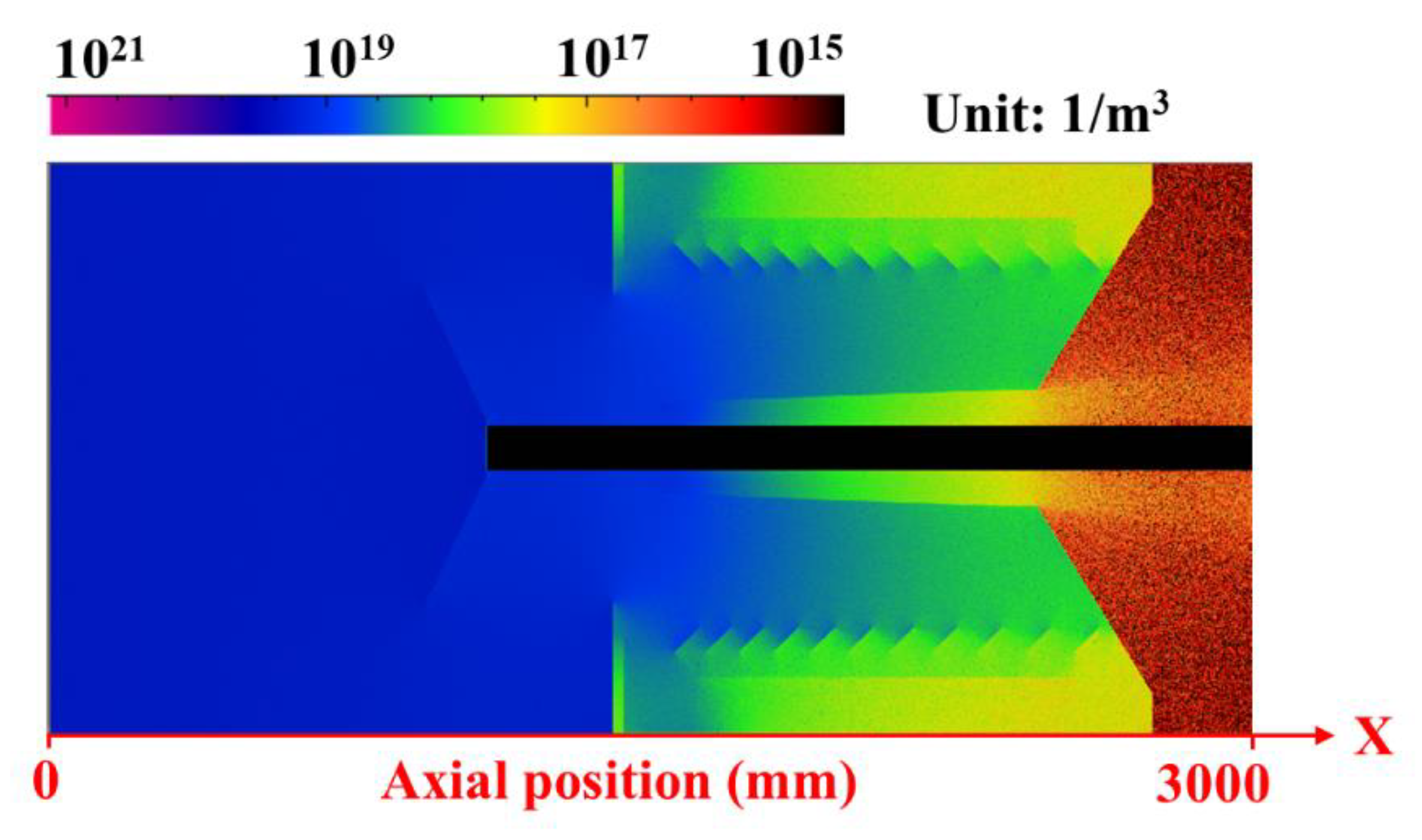
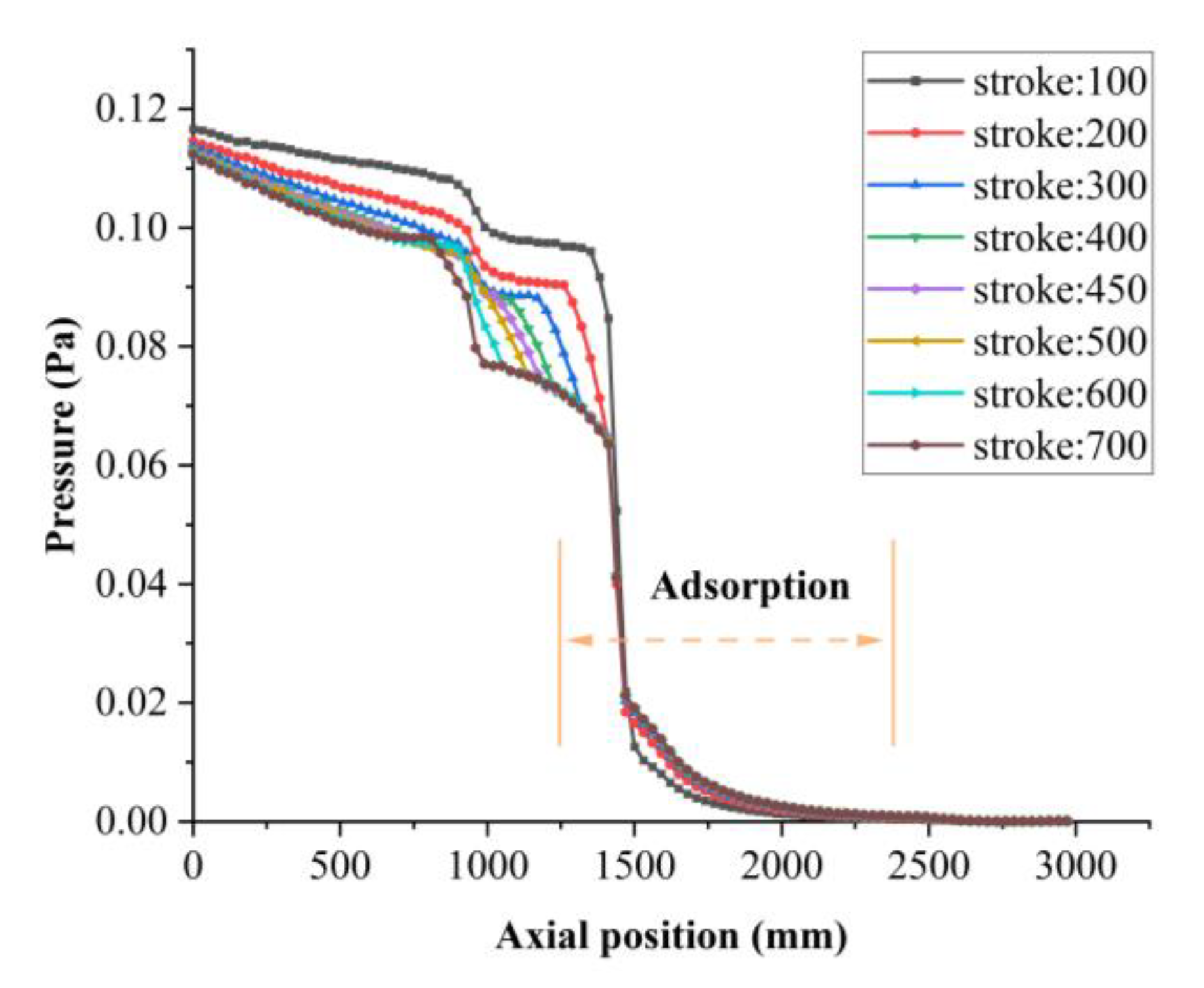
4.3. Estimation of the Transmission Probability

Figure 13 shows the relationship between the transmission probability of the cryopump and the stroke of the inlet valve. It can be seen that the transmission probability increases dramatically from 0 at a 0 mm stroke to 0.181 at a 500 mm stroke, and beyond a 500 mm stroke, it barely increases with the stroke of the inlet valve. Owing to the limitations of installation space and structural strength, it is necessary to find a balance between the pumping speed and the structural strength of the pump; that is, to ensure that the transmission probability of the cryopump is as large as possible while minimizing the stroke of the inlet valve. As a result, two groups of models (450 mm stroke and 500 mm stroke) with relatively large transmission probability and short strokes are selected, and the structural analysis of ones under normal operating conditions is carried out.
Figure 12 and Figure 14 display the stress and deformation distributions of the inlet valve mock-up at a 450 mm stroke and a 500 mm stroke, respectively. The computational parameters are listed in Table 4. The maximum stress of the above two models is far less than the allowable stress of the valve material of 170 MPa. However, the maximum deformation of the inlet valve exceeds 0.7 mm at a 500 mm stroke; thus, the maximum valve stroke is set to 450 mm.
The pressure profile of deuterium gas in the model has been studied in order to provide some important information during the operation phase of the cryopump, which can predict the pump behavior. In Figure 15, the corresponding pressure profile of deuterium gas along the axial position of the model at the 450 mm stroke is presented. It is noted that the pressure decreases in the X direction. Because the flow pressure is directly relevant to the number of particles, the adsorption on the cryogenic surface results in the decrease in the number of particles, leading to a drastic reduction in pressure. An extreme example is when the pressure of deuterium gas will be zero when all particles are adsorbed. The particle density profile is shown in Figure 16. The pressure profile of the deuterium gas at different strokes of the inlet valve is provided in Figure 17. It is seen that the deuterium pressure in the vacuum duct gradually decreases along the axial direction, and the speed of reduction is related to the stroke of the inlet valve. The larger the stroke of the inlet valve, the faster the pressure decreases. Moreover, the pressure within the cryopump does not rely on the stroke of the inlet valve at constant gas throughput and is nearly the same close to the end of the pump. The pressure of the deuterium gas that is greatly affected by the adsorption is reduced to the order of 10−4 Pa in the cryopump, which meets the pump operation requirements. The adsorption region is labeled in Figure 17.

4.4. Seismic Analysis of the Inlet Valve

Under the combined loads of the sealing force and the seismic load, the stress and deformation distributions of the valve disc are depicted in Figure 18. The maximum stress is about 243.72 MPa and occurred at the bolt opening at the bottom of the valve disc, and the maximum deformation is about 0.90 mm and occurred at the bottom of the valve disc. Under the combined loads of the gravity and the seismic load, the stress and deformation distributions of the valve disc are depicted in Figure 19. The maximum stress is about 19.49 MPa and occurred at the contact between the valve shaft and the front bearing, and the maximum deformation is about 0.686 mm and occurred at the outer edge of the valve disc. It can be seen that the effect of the seismic load on the stress of the inlet valve is 1.45%, and the effect of the bending deformation on the inlet valve is 1.63%. The safety factor of the inlet valve under the seismic load is 2.0, and the mechanical performance of the inlet valve meets CFETR torus cryopump requirements.

5. Conclusions

This paper shows how the inlet valve, a key component of the CFETR torus cryopump, is designed, analyzed, and optimized. There are four design options for the valve disc and the structure of the valve disc is optimized for the best mechanical properties. According to the analysis results, the disk-shaped valve disc is the optimal design. The thickness of the valve disc is 10 mm, the maximum stress is about 240.23 MPa and located at the bolt opening at the bottom of the valve disc, and the maximum deformation is about 0.895 mm in the bottom edge of the valve disc. In order to prevent excessive bending deflection of the inlet valve from affecting the sealing performance, the valve shaft is analyzed and optimized. Its inner diameter and outer diameter are 80 mm and 120 mm, respectively. The maximum stress is about 15.863 MPa located at the contact between the valve shaft and the front bearing, and the maximum deformation is about 0.675 mm located at the outer edge of the valve disc. In order to study the influence of the inlet valve on the pumping performance of the cryopump, the transmission probability of the inlet valve at different strokes was calculated. It was found that the stroke of the inlet valve has little effect on the final pressure in the cryopump after adsorption, and the final pressure in the pump is on the order of 10−4 Pa. The seismic capacity of the inlet valve was analyzed. The effect of the seismic load on the stress of the inlet valve is 1.45%, and the effect of the bending deformation on the inlet valve is 1.63%. The safety factor of the inlet valve under the seismic load is 2.0, so the mechanical properties of the inlet valve meet the operating requirements. These verify that the design scheme of the inlet valve is feasible. We hope all the design and analysis results provide support for investigation of the torus cryopump. A future step is to benchmark the current analysis results with corresponding experimental data.

Author Contributions

Methodology, Y.Z. and Z.Z.; Data curation, S.Z.; Writing—original draft, Y.Z.; Writing—review & editing, M.Z.; Supervision, H.F.; Project administration, H.F. All authors have read and agreed to the published version of the manuscript.

Funding

This research received no external funding.

Data Availability Statement

The data that support the findings of this study are available from the corresponding author upon reasonable request. The data that supports the findings of this study are available within the article.

Acknowledgments

The author is grateful to his colleagues who worked in the past on the design of the torus cryopumps in the Institute of Plasma Physics.

Conflicts of Interest

The authors declare that they have no known competing financial interests or personal relationships that could have appeared to influence the work reported in this paper.

References

  1. Mao, S.; Ye, M.; Li, Y.; Zhang, J.; Zhan, X.; Wang, Z.; Xu, K.; Liu, X.; Li, J. CFETR integration design platform: Overview and recent progress. Fusion Eng. Des. 2019, 146, 1153–1156. [Google Scholar] [CrossRef]
  2. Wan, Y.; Li, J.; Liu, Y.; Wang, X.; Chan, V.; Chen, C.; Duan, X.; Fu, P.; Gao, X.; Feng, K.; et al. Overview of the present progress and activities on the CFETR. Nucl. Fusion 2017, 57, 102009. [Google Scholar] [CrossRef]
  3. Zhuang, G.; Li, G.; Li, J.; Wan, Y.; Liu, Y.; Wang, X.; Song, Y.; Chan, V.; Yang, Q.; Wan, B.; et al. Progress of the CFETR design. Nucl. Fusion 2019, 59, 112010. [Google Scholar] [CrossRef]
  4. Glugla, M.; Antipenkov, A.; Beloglazov, S.; Caldwell-Nichols, C.; Cristescu, I.R.; Cristescu, I.; Day, C.; Doerr, L.; Girard, J.P.; Tada, E. The ITER tritium systems. Fusion Eng. Des. 2007, 82, 472–487. [Google Scholar] [CrossRef]
  5. Dremel, M.; Pearce, R.; Strobel, H.; Hauer, V.; Day, C.; Wikus, P.; Papastergiou, S. The new build to print design of the ITER Torus Cryopump. Fusion Eng. Des. 2013, 88, 760–763. [Google Scholar] [CrossRef]
  6. Li, Y.; Zhang, Z.; Qiu, Y.; Zha, F.; Li, Q. Pumping Performance Evaluation of HL-2M In-Vessel Cryopump With Monte Carlo Method. IEEE Trans. Plasma Sci. 2017, 46, 1587–1591. [Google Scholar] [CrossRef]
  7. Lee, H.; Park, Y.; Chang, Y.; Kim, J.; Lee, D.; Yang, H.; Bozek, A.; Smith, J.; Anderson, P. Design and fabrication of the KSTAR in-vessel cryo-pump. Fusion Eng. Des. 2011, 86, 1993–1996. [Google Scholar] [CrossRef]
  8. Mukherjee, S.; Panchal, P.; Nayak, P.; Gupta, V.; Das, S.; Mishra, J.; Gangradey, R. Nitrogen and water vapor pumping study on a 400 mm opening LN2 cooled sorption cryopump. Vacuum 2020, 184, 109883. [Google Scholar] [CrossRef]
  9. Gangradey, R.; Mukherjee, S.S.; Gupta, V.; Panchal, P.; Nayak, P.; Mishra, J.S.; Dewasi, A.; Verma, S.K. Design and development of a liquid nitrogen cooled test cryopump for application in Steady-state Superconducting Toka-mak-1. Vacuum 2022, 200, 110986. [Google Scholar] [CrossRef]
  10. Kovari, M.; Clarke, R.; Shephard, T. Compound cryopump for fusion reactors. Fusion Eng. Des. 2013, 88, 3293–3298. [Google Scholar] [CrossRef] [Green Version]
  11. Pedroche, G.; Lopez-Revelles, A.; Kolsek, A.; Dremel, M.; Bansal, G.; Pearce, R.; Sanz, J.; Juarez, R. Nuclear analysis of the ITER torus cryopumps. Nucl. Fusion 2019, 59, 106045. [Google Scholar] [CrossRef]
  12. Day, C.; Murdoch, D.; Pearce, R. The vacuum systems of ITER. Vacuum 2008, 83, 773–778. [Google Scholar] [CrossRef]
  13. Hu, J.; Cao, Z.; Zuo, G.; Yuan, J.; Zhuang, H.; Xu, H.; Cao, C.; Chen, Y.; Yuan, X.; Yu, Y.; et al. Progress of engineering design of CFETR vacuum systems. Fusion Eng. Des. 2022, 177. [Google Scholar] [CrossRef]
  14. Liu, C.; Lu, K.; Sheng, L.; Song, Y.; Su, J.; Su, M.; Gung, C. Manufacture and test of seismic bellows for ITER magnet feeder. Fusion Eng. Des. 2016, 109–111, 515–520. [Google Scholar] [CrossRef]
  15. Hauer, V.; Boissin, J.-C.; Day, C.; Haas, H.; Mack, A.; Murdoch, D.; Lässer, R.; Wykes, M. Design of the ITER torus prototype cryopump. Fusion Eng. Des. 2007, 82, 2113–2119. [Google Scholar] [CrossRef]
  16. Day, C.; Antipenkov, A.; Dremel, M.; Haas, H.; Hauer, V.; Mack, A.; Murdoch, D.; Wykes, M. R&D and design for the cryogenic and mechanical vacuum pumping systems of ITER. Vacuum 2007, 81, 738–747. [Google Scholar]
  17. Yoshida, H.; Shiro, M.; Arai, K.; Akimichi, H.; Hirata, M. Calculation and uncertainty evaluation of conductance of a precise orifice for orifice-flow method. Vacuum 2009, 84, 277–279. [Google Scholar] [CrossRef]
  18. Luo, X.; Scannapiego, M.; Day, C.; Sakurai, S. Assessment of the JT-60SA divertor cryopump performance. Fusion Eng. Des. 2018, 136, 467–471. [Google Scholar] [CrossRef]
  19. Lang, J.; Hu, C.; Xie, Y.; Tong, Y. Optimization Analysis of the Structural Design of NNBI Cryosorption Pumps. Energies 2021, 14, 3628. [Google Scholar] [CrossRef]
  20. Scannapiego, M.; Day, C.; Hauer, V. Consequences of plasma disruption mitigation by massive gas injection on the ITER torus cryopumping system. Fusion Eng. Des. 2014, 89, 2446–2450. [Google Scholar] [CrossRef]
  21. Mohan, A.; Tompson, R.V.; Loyalka, S.K. Efficient numerical solution of the Clausing problem. J. Vac. Sci. Technol. A Vac. Surf. Film. 2007, 25, 758–762. [Google Scholar] [CrossRef]
  22. Clausing, P. The flow of highly rarefied gases through tubes of arbitrary length. J. Vac. Sci. Technol. 1971, 8, 636–646. [Google Scholar] [CrossRef]
Figure 1. Vertical cut view of lower port of the vacuum vessel from the divertor to the torus cryopump.
Energies 16 03107 g001
Figure 2. Overview structure of the inlet valve of torus cryopump.
Energies 16 03107 g002
Figure 3. Schematic diagram of the seal at the cryopump inlet. Valve disc (1); front flange (2); spring loaded all-metal double seal ring (3).
Energies 16 03107 g003
Figure 4. Four types of valve disc. Td is thickness of the valve disc. Rectangular valve disc (a); fillet valve disc (b); stepped valve disc (c); disk-shaped valve disc (d).
Energies 16 03107 g004
Figure 5. Process flow diagram of the control system of the pneumatic actuator.
Energies 16 03107 g005
Figure 6. The physical model of the cryopump. Inlet valve (1); thermal radiation shield (2); cryopanels (3); louver baffle (4); pump casing (5); vacuum duct (6).
Energies 16 03107 g006
Figure 7. Grid independency investigation (maximum deformations with different grid numbers).
Energies 16 03107 g007
Figure 8. Stress and deformation distributions of four types of valve discs in initial design. (a) Stress (left) and deformation (right) distribution of the rectangular valve disc. (b) Stress (left) and deformation (right) distribution of the fillet valve disc. (c) Stress (left) and deformation (right) distribution of the stepped valve disc. (d) Stress (left) and deformation (right) distribution of the disk-shaped valve disc.
Energies 16 03107 g008
Figure 9. Maximum stress and deformation of the disk-shaped valve disc at different thicknesses.
Energies 16 03107 g009
Figure 10. Maximum stress and deformation of the valve shaft at different outer diameters.
Energies 16 03107 g010
Figure 11. The effect of different valve shaft outer diameters on the mechanical performance of the inlet valve.
Energies 16 03107 g011
Figure 12. Stress (left) and deformation (right) distribution of the inlet valve with the valve shaft outside diameter of 120 mm at 450 mm stroke.
Energies 16 03107 g012
Figure 13. Transmission probability of cryopump at different strokes of the inlet valve.
Energies 16 03107 g013
Figure 14. Stress (left) and deformation (right) distribution of the inlet valve with the valve shaft outside diameter of 120 mm at 500 mm stroke.
Energies 16 03107 g014
Figure 15. Pressure profile of deuterium gas in the model. X is the axial position.
Energies 16 03107 g015
Figure 16. Particle density profile in the model. X is the axial position.
Energies 16 03107 g016
Figure 17. Pressure profile of deuterium gas in axial position of the model.
Energies 16 03107 g017
Figure 18. Stress (left) and deformation (right) distributions of the valve disc under the combined loads of the sealing force and seismic load.
Energies 16 03107 g018
Figure 19. Stress (left) and deformation (right) distributions of the inlet valve under the combined loads of the gravity and seismic load.
Energies 16 03107 g019
Table 1. Seismic acceleration of Hefei.
X DirectionY DirectionZ Direction
3.42 m/s23.00 m/s22.29 m/s2
Table 2. The transmission probabilities of cylinders calculated with the Monte Carlo Method and the Clausing integral equation.
L/RMonte CarloClausing EquationMC Relative Error (×10−5)
0.50.8012650.801271−0.6
10.6719730.671983−1.0
20.5142250.514230−0.5
50.3105260.3105250.1
100.1909390.190942−0.3
200.1093140.109320−0.6
500.0484750.048476−0.1
Table 3. Maximum stress and Maximum deformation of different types and thickness of valve disc.
Type of Valve DiscThickness (mm)Maximum Stress (MPa)Maximum Deformation (mm)
Rectangular valve disc8687.74389.64
Fillet valve disc8425.6979.65
Stepped valve disc8393.8829.02
Disk-shaped valve disc8240.561.10
Disk-shaped valve disc10240.230.89
Disk-shaped valve disc12240.080.76
Table 4. The computational parameters of the inlet valve analysis.
Stroke (mm)Transmission ProbabilityMaximum Deformation (mm)Maximum Stress (MPa)
4500.1780.6815.86
5000.1810.7516.99
Disclaimer/Publisher’s Note: The statements, opinions and data contained in all publications are solely those of the individual author(s) and contributor(s) and not of MDPI and/or the editor(s). MDPI and/or the editor(s) disclaim responsibility for any injury to people or property resulting from any ideas, methods, instructions or products referred to in the content.

