

Design and Optimization of Synchronous Motor Using PM Halbach Arrays for Rim-Driven Counter-Rotating Pump
 , ,
, ,  , , , and
Abstract
:1. Introduction
2. Electromagnetic Design
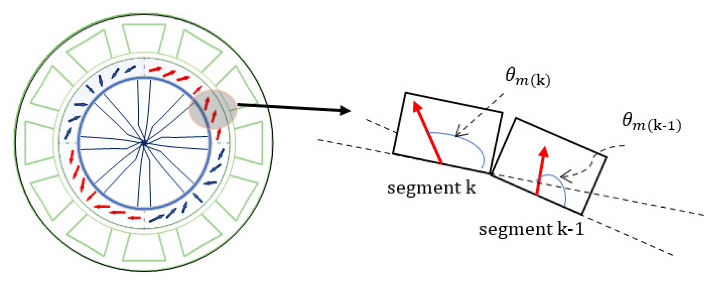
2.1. Design of Halbach Array Permanent Magnets
2.2. Magnetic Circuit Design
2.2.1. Tooth Sizing
2.2.2. Yokes Thickness
2.2.3. Slot Sizing
2.3. Machine Efficiency
3. Thermal Sizing
3.1. Iron Losses
3.2. Copper Losses
3.3. Iron Part Thermal Circuit Modeling
3.4. Slot and Winding Modeling
3.5. Heat Transfer Modeling
- The lateral surfaces are in contact with a gas (natural air or hydrogen).
- The internal surfaces are in contact with the liquid pushed by the blades of the rotor.
- For the external surface, the Nusselt number is given by:is the Reynolds number, and represents the Prendt factor.
- For the internal side (gap), the determination of is more complex. In the literature, there are several formulas that are used in the case of a thin space. In this paper, the expression used is the one described in [19]. is decomposed into an axial component and tangential component . The Nusselt number for the axial convection, , is given by Equation (23), and for the tangential convection, the Nusselt number is expressed in Equation (24)represents the Taylor number, which is given as a function of rotor speed, the geometry of the machine and the characteristics of the fluid that crosses the airgap.
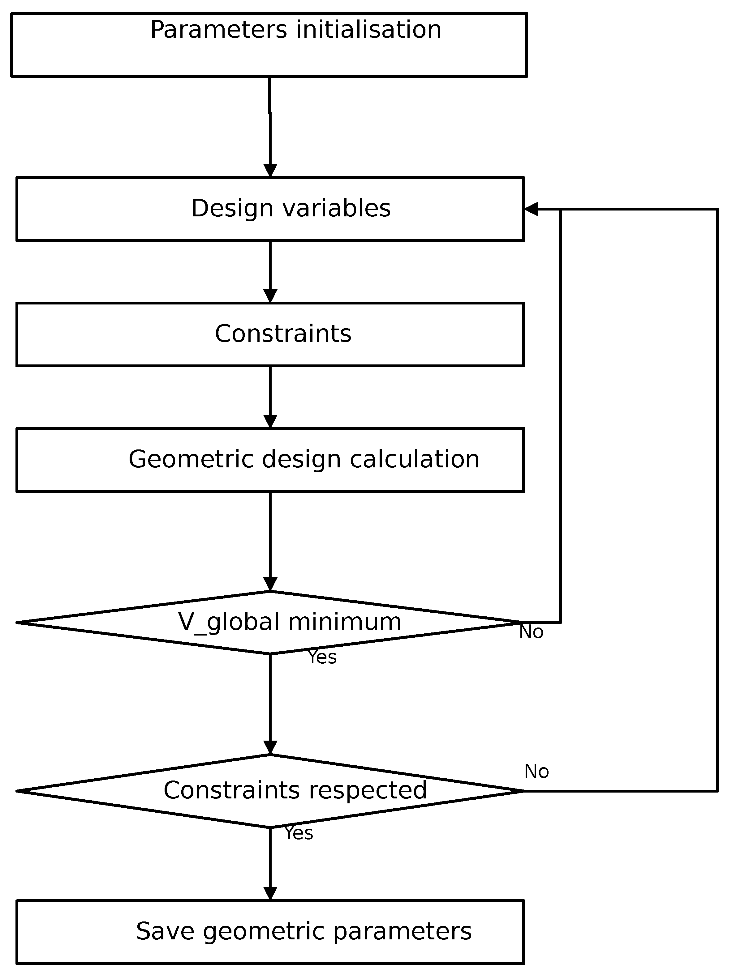
4. Optimization Strategy, Objective, and Constraints
4.1. Strategy
4.2. Design Variables
4.3. Objective
4.4. Constraints
4.5. Optimization Results
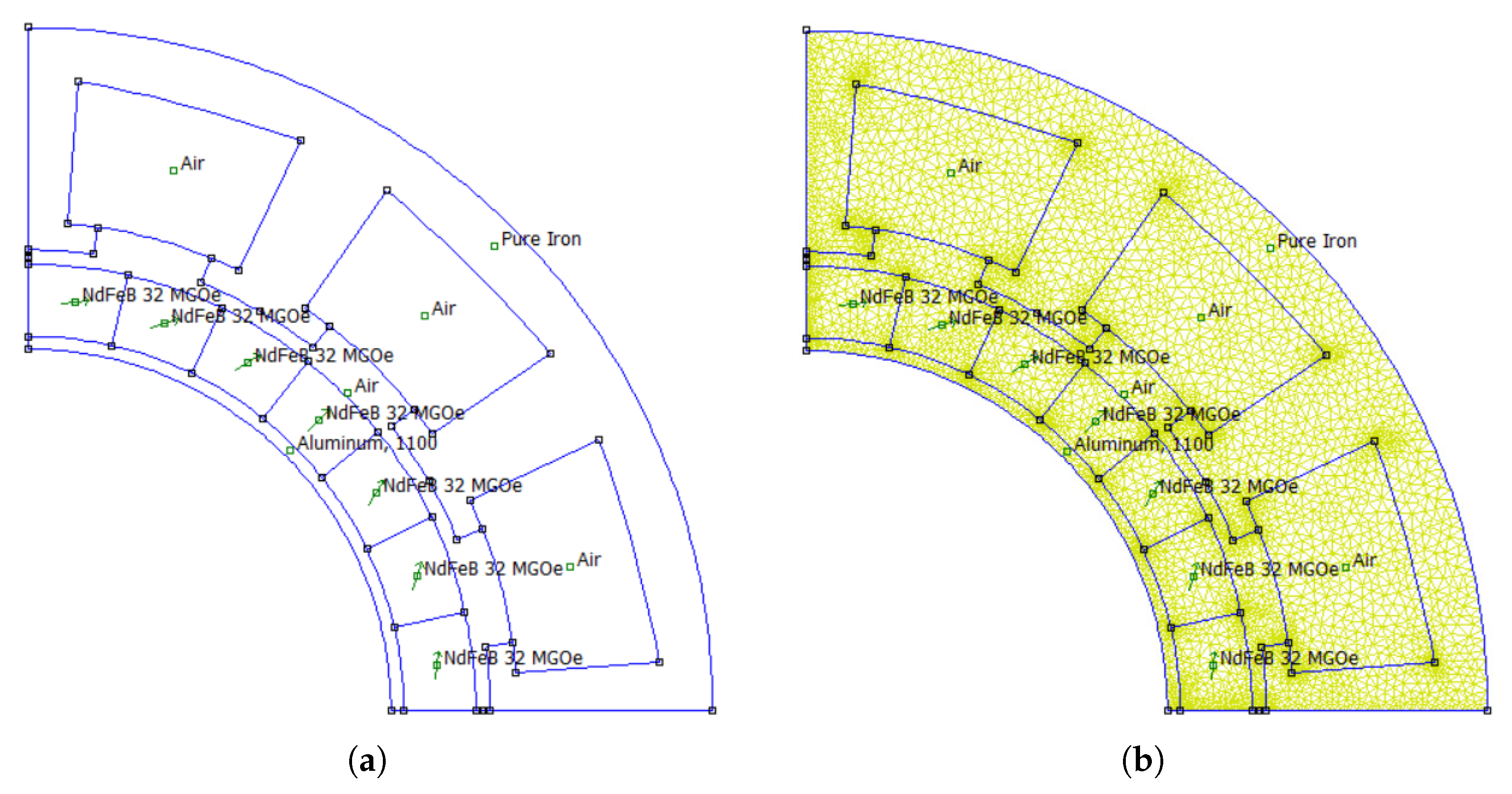
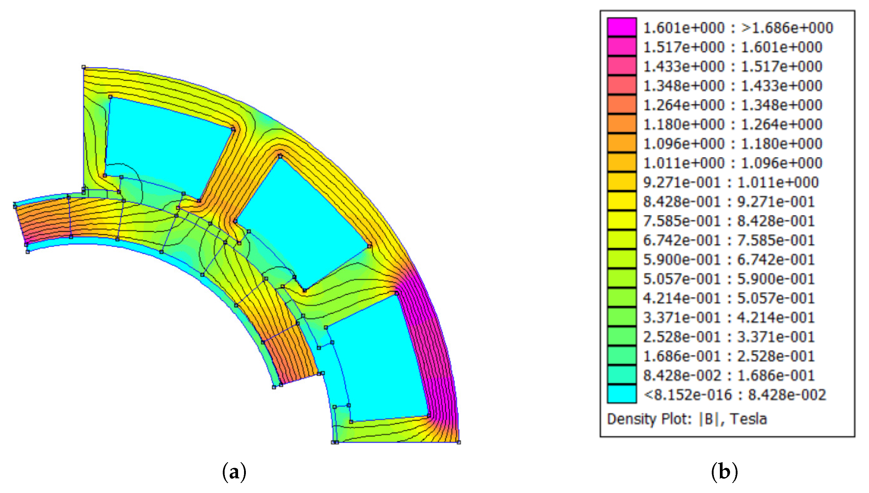
5. Finite Elements Method
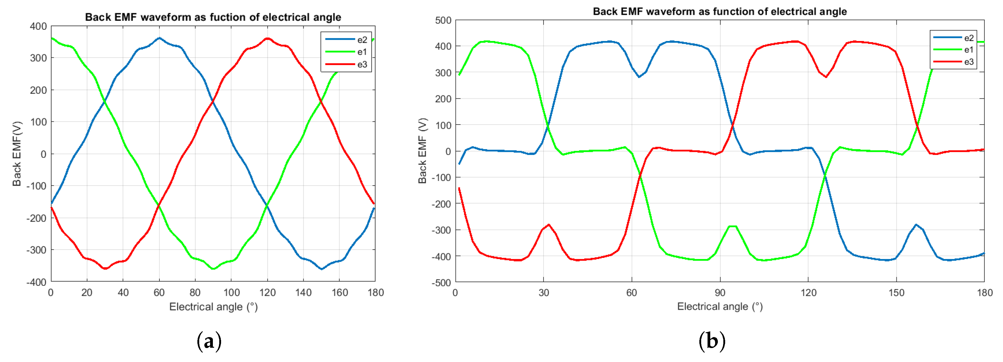
5.1. Flux Density and Back Electromotive Force
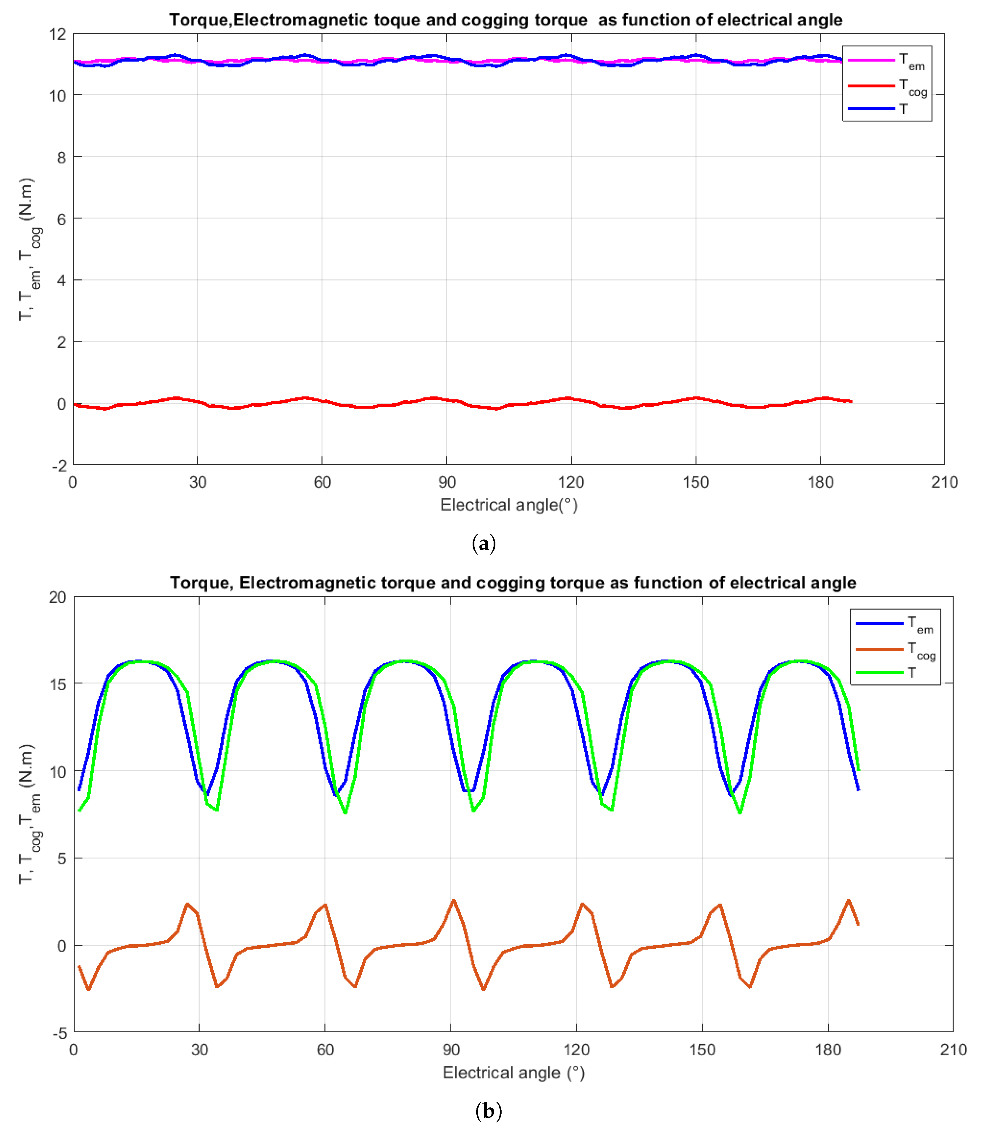
5.2. Electromagnetic Torque and Cogging Torque
6. Conclusions
Author Contributions
Funding
Institutional Review Board Statement
Informed Consent Statement
Data Availability Statement
Conflicts of Interest
Appendix A
- Thermal model formulas
References
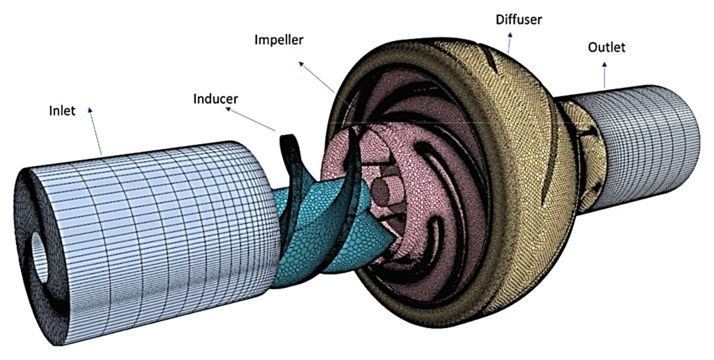
- Dehnavi, E.; Kebdani, M.; Danlos, A.; Moises, S.; Bakir, F. Numerical analysis of Counter-Rotating Pump (CRP) including inducer and centrifugal impeller. In Proceedings of the 25ème Congrès Français de Mécanique Nantes, Nantes, France, 29 August–2 September 2022. [Google Scholar]
- Tuohy, P.M.; Smith, A.C.; Husband, M.; Hopewell, P. Rim-drive marine thruster using a multiple-can induction motor. IET Electr. Power Appl. 2013, 7, 557–565. [Google Scholar] [CrossRef]
- Zhao, H.; Eldeeb, H.H.; Zhan, Y.; Ren, Z.; Xu, G.; Mohammed, O.A. Robust Electromagnetic Design of Double-Canned IM for Submergible Rim Driven Thrusters to Reduce Losses and Vibration. IEEE Trans. Energy Convers. 2020, 35, 2045–2055. [Google Scholar] [CrossRef]
- Bolam, R.C.; Vagapov, Y. Implementation of electrical rim driven fan technology to small unmanned aircraft. In Proceedings of the 2017 Internet Technologies and Applications (ITA), Wrexham, UK, 12–15 September 2017; pp. 35–40. [Google Scholar] [CrossRef]
- Touimi, K.; Benbouzid, M.; Chen, Z. Optimal Design of a Multibrid Permanent Magnet Generator for a Tidal Stream Turbine. Energies 2020, 13, 487. [Google Scholar] [CrossRef] [Green Version]
- Zhou, Z.; Benbouzid, M.; Charpentier, J.F.; Scuiller, F.; Tang, T. Developments in large marine current turbine technologies—A review. Renew. Sustain. Energy Rev. 2017, 71, 852–858. [Google Scholar] [CrossRef]
- Kaiser, B.E.; Poroseva, S.V.; Snider, M.A.; Hovsapian, R.O.; Johnson, E. Flow Simulation Around a Rim-Driven Wind Turbine and in Its Wake; Amer Soc Mechanical Engineers: New York, NY, USA, 2013. [Google Scholar]
- Djebarri, S.; Charpentier, J.F.; Scuiller, F.; Benbouzid, M.; Guemard, S. Rough Design of a Double-Stator Axial Flux Permanent Magnet Generator for a Rim-Driven Marine Current Turbine. In Proceedings of the 2012 IEEE International Symposium on Industrial Electronics, Hangzhou, China, 28–31 May 2012. [Google Scholar] [CrossRef] [Green Version]
- Li, Y.; Song, B.; Mao, Z.; Tian, W. Analysis and Optimization of the Electromagnetic Performance of a Novel Stator Modular Ring Drive Thruster Motor. Energies 2018, 11, 1598. [Google Scholar] [CrossRef] [Green Version]
- Bolam, R.C.; Vagapov, Y.; Laughton, J.; Anuchin, A. Optimum Performance Determination of Single-Stage and Dual-Stage (Contra-Rotating) Rim Driven Fans for Electric Aircraft. In Proceedings of the 2020 XI International Conference on Electrical Power Drive Systems (ICEPDS), IEEE, Saint Petersburg, Russia, 4–7 October 2020; pp. 1–6. [Google Scholar]
- Ojaghlu, P.; Vahedi, A. Specification and Design of Ring Winding Axial Flux Motor for Rim-Driven Thruster of Ship Electric Propulsion. IEEE Trans. Veh. Technol. 2019, 68, 1318–1326. [Google Scholar] [CrossRef]
- Cheng, B.; Pan, G.; Cao, Y. Analytical design of the integrated motor used in a hubless rim-driven propulsor. IET Electr. Power Appl. 2019, 13, 1255–1262. [Google Scholar] [CrossRef]
- Amri, L.; Kebdani, M.; Zouggar, S.; Charpentier, J.F. Design and optimization of a rim driven motor for pump application. Mater. Today Proc. 2022, 72, 3775–3779. [Google Scholar] [CrossRef]
- Atallah, K.; Howe, D. The application of Halbach cylinders to brushless ac servo motors. IEEE Trans. Magn. 1998, 34, 2060–2062. [Google Scholar] [CrossRef]
- Dwari, S.; Parsa, L. Design of Halbach-Array-Based Permanent-Magnet Motors With High Acceleration. IEEE Trans. Ind. Electron. 2011, 58, 3768–3775. [Google Scholar] [CrossRef]
- Sakamoto, H.; Harada, K.; Abe, H.; Tokuomi, S. A magnetic coupled charger with no-load protection. IEEE Trans. Magn. 1998, 34, 2057–2059. [Google Scholar] [CrossRef]
- Drouen, L.; Hauville, F.; Charpentier, J.F.; Semail, E.; Clénet, S. A coupled electromagnetic/hydrodynamic model for the design of an integrated rim- driven naval propulsion system. In Proceedings of the ElectrIMACS, Quebec City, QC, Canada, 8–11 June 2008. [Google Scholar]
- Agrebi, H.Z.; Benhadj, N.; Chaieb, M.; Sher, F.; Amami, R.; Neji, R.; Mansfield, N. Integrated Optimal Design of Permanent Magnet Synchronous Generator for Smart Wind Turbine Using Genetic Algorithm. Energies 2021, 14, 4642. [Google Scholar] [CrossRef]
- Drouen, L.; Charpentier, J.; Hauville, F.; Astolfi, J.; Semail, E.; Clenet, S. A multi physical approach for the design of RIM-DRIVEN Tidal Turbines. La Houille Blanche 2015, 101, 14–21. [Google Scholar] [CrossRef] [Green Version]
- Martínez, D. Design of a Permanent-Magnet Synchronous Machine with Non- Overlapping Concentrated Windings for the Shell Eco Marathon Urban Prototype. Master’s Thesis, KTH Royal Institute of Technology, Stockholm, Sweden, 2012. [Google Scholar]
- Krøvel, Ø.; Nilssen, R.; Skaar, S.E.; Løvli, E.; Sandoy, N. “Design of an integrated 100kW Permanent Magnet Synchronous Machine in a Prototype Thruster for Ship Propulsion” in CD Rom. In Proceedings of the ICEM’2004, Cracow, Poland, 5–8 September 2004; pp. 117–118. [Google Scholar]
- Hanselman, D. Brushless Permanent Magnet Motor Design; The Writers’ Collective: Cranston, RI, USA, 2003. [Google Scholar]
- Mellor, P.H.; Roberts, D.; Turner, D.R. Lumped parameter thermal model for electrical machines of TEFC design. IEE Proc. B (Electr. Power Appl.) 1991, 138, 205–218. [Google Scholar] [CrossRef]
- Proca, A.; Keyhani, A.; El-Antably, A.; Lu, W.; Dai, M. Analytical model for permanent magnet motors with surface mounted magnets. IEEE Trans. Energy Convers. 2003, 18, 386–391. [Google Scholar] [CrossRef]
- Chebak, A.; Viarouge, P.; Cros, J. Analytical Model for Design of High-Speed Slotless Brushless Machines with SMC Stators. In Proceedings of the 2007 IEEE International Electric Machines and Drives Conference, Antalya, Turkey, 3–5 May 2007; Volume 1, pp. 159–164. [Google Scholar] [CrossRef]
- Perez, I.J.; Kassakian, J.G. A Stationary Thermal Model for Smooth Air-Gap Rotating Electric Machines. Electr. Mach. Power Syst. 1979, 3, 285–303. [Google Scholar] [CrossRef]
- Irasari, P.; Alam, H.; Kasim, M. Magnetic Simulation and Analysis of Radial Flux Permanent Magnet Generator using Finite Element Method. J. Mechatron. Electr. Power Veh. Technol. 2012, 3, 23–30. [Google Scholar] [CrossRef] [Green Version]
- Abbasnezhad, N.; Kebdani, M.; Shirinbayan, M.; Champmartin, S.; Tcharkhtchi, A.; Kouidri, S.; Bakir, F. Development of a Model Based on Physical Mechanisms for the Explanation of Drug Release: Application to Diclofenac Release from Polyurethane Films. Polymers 2021, 13, 1230. [Google Scholar] [CrossRef] [PubMed]
- Vijayan, A.K.; Xiao, D.; Batkhishig, B.; Callegaro, A.D.; Baranwal, R.; Emadi, A. Comparative Study on Pulse Pattern Optimization for High-Speed Permanent Magnet Synchronous Motors. In Proceedings of the 2022 IEEE Transportation Electrification Conference and Expo (ITEC), Haining, China, 28–31 October 2022; pp. 708–713. [Google Scholar] [CrossRef]
- Karnavas, Y.L.; Korkas, C.D. Optimization methods evaluation for the design of radial flux surface PMSM. In Proceedings of the 2014 International Conference on Electrical Machines (ICEM), IEEE, Berlin, Germany, 2–5 September 2014; pp. 1348–1355. [Google Scholar]
- Dridi, S.; Salem, I.B.; Amraoui, L.E. A Multi-Energetic Modeling Approach based on Bond Graph Applied to In-Wheel-Motor Drive System. Int. J. Adv. Comput. Sci. Appl. 2018, 9, 422–429. [Google Scholar] [CrossRef] [Green Version]
- Marquis-Favre, W.; Jardin, A. Bond Graphs and Inverse Modeling for Mechatronic System Design. In Bond Graph Modelling of Engineering Systems: Theory, Applications and Software Support; Borutzky, W., Ed.; Springer: New York, NY, USA, 2011; pp. 195–226. [Google Scholar] [CrossRef]
- Kebdani, M.; Dauphin-Tanguy, G.; Dazin, A.; Albach, R.; Dupont, P. Two-phase reservoir: Development of a transient thermo-hydraulic model based on bond graph approach with experimental validation. Math. Comput. Model. Dyn. Syst. 2017, 23, 476–503. [Google Scholar] [CrossRef]
- Kebdani, M.; Dauphin-Tanguy, G.; Dazin, A.; Dupont, P. Experimental development and bond graph dynamic modelling of a brazed plate heat exchanger. Int. J. Simul. Process Model. 2017, 12, 249–263. [Google Scholar] [CrossRef] [Green Version]
- Felez, J.; Romero, G.; Maroto, J.; Martinez, M.L. Simulation of Multi-body Systems Using Multi-bond Graphs. In Bond Graph Modelling of Engineering Systems: Theory, Applications and Software Support; Borutzky, W., Ed.; Springer: New York, NY, USA, 2011; pp. 323–354. [Google Scholar] [CrossRef]
- Mohammed, A.; Sirahbizu, B.; Lemu, H.G. Optimal Rotary Wind Turbine Blade Modeling with Bond Graph Approach for Specific Local Sites. Energies 2022, 15, 6858. [Google Scholar] [CrossRef]


| Parameter | Symbol | Unit | Value |
|---|---|---|---|
| Turbine external diameter | mm | 80 | |
| Remanence of the magnet | T | 1.2 | |
| Rotor yoke thickness | mm | 7.67 | |
| Pole pair number | p | 3 |
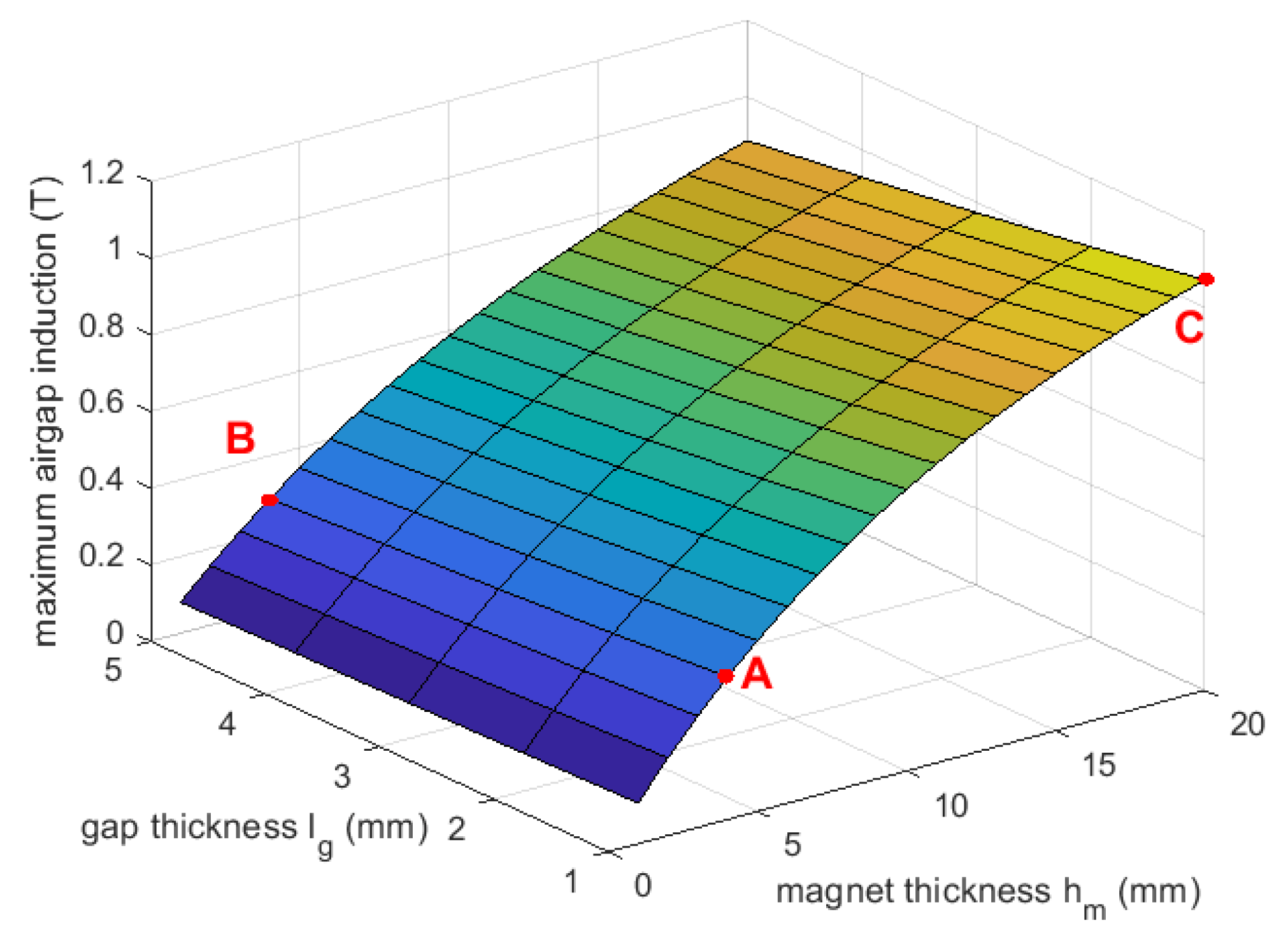
| Point | (mm) | (mm) | |
|---|---|---|---|
| A | 1 | 4 | 0.372 |
| B | 5 | 4 | 0.2881 |
| C | 1 | 20 | 1.071 |
| Parameter | Unit | Symbol | Value |
|---|---|---|---|
| Rated speed | rpm | 5000 | |
| Rated torque | N·m | 10 | |
| Propeller diameter | m | 0.08 | |
| Airgap to propeller ratio | - |
| Parameter | Symbol | Unit | Range of Variation |
|---|---|---|---|
| Current density | J | ||
| Electrical load | A/mm | ||
| Pole pair number | p | − | |
| Magnet height | mm | ||
| Active length | L | mm |
| Parameter | Symbol | Unit | MMS | HAPM |
|---|---|---|---|---|
| Current density | J | 3.5 | 3.5001 | |
| Electrical load | A/mm | 20.196 | 20 | |
| Pole pair number | p | − | 2 | 2 |
| Maximal flux density | T | 0.6831 | 0.6950 | |
| Active length | L | mm | 100 | 124.4 |
| Total volume | V |
| Parameter | Unit | MMS | HAPM |
|---|---|---|---|
| L | mm | 100 | 124.36 |
| D | mm | 109.13 | 102.06 |
| mm | 12.84 | 5.73 | |
| mm | 12.84 | 1.4 | |
| mm | 1.56 | 8 | |
| mm | 28.29 | 16.3 | |
| mm | 25 | 11.5 | |
| mm | 10.00 | 10.0008 |
| Material | Characteristics | |
|---|---|---|
| Permeability | 14,872 | |
| Iron | Electrical conductivity | 10.44 MS/m |
| Thermal conductivity | 76.2 W/m·K | |
| Magnets | Remanent flux density | 1.2 T |
| Coercivity | 836.42 kA/m | |
| Electrical conductivity | 0.667 MS/m | |
| Work temperature | 80 °C | |
| Structure | Analytical Value (V) | FEM Value (V) | Error (%) |
|---|---|---|---|
| HAPMS | 222 | 254.55 | 12 |
Disclaimer/Publisher’s Note: The statements, opinions and data contained in all publications are solely those of the individual author(s) and contributor(s) and not of MDPI and/or the editor(s). MDPI and/or the editor(s) disclaim responsibility for any injury to people or property resulting from any ideas, methods, instructions or products referred to in the content. |
© 2023 by the authors. Licensee MDPI, Basel, Switzerland. This article is an open access article distributed under the terms and conditions of the Creative Commons Attribution (CC BY) license (https://creativecommons.org/licenses/by/4.0/).
Share and Cite
Amri, L.; Zouggar, S.; Charpentier, J.-F.; Kebdani, M.; Senhaji, A.; Attar, A.; Bakir, F. Design and Optimization of Synchronous Motor Using PM Halbach Arrays for Rim-Driven Counter-Rotating Pump. Energies 2023, 16, 3070. https://doi.org/10.3390/en16073070
Amri L, Zouggar S, Charpentier J-F, Kebdani M, Senhaji A, Attar A, Bakir F. Design and Optimization of Synchronous Motor Using PM Halbach Arrays for Rim-Driven Counter-Rotating Pump. Energies. 2023; 16(7):3070. https://doi.org/10.3390/en16073070
Chicago/Turabian StyleAmri, Lahcen, Smail Zouggar, Jean-Frédéric Charpentier, Mohamed Kebdani, Abdelhamid Senhaji, Abdelilah Attar, and Farid Bakir. 2023. "Design and Optimization of Synchronous Motor Using PM Halbach Arrays for Rim-Driven Counter-Rotating Pump" Energies 16, no. 7: 3070. https://doi.org/10.3390/en16073070