Article

Design and Operation of Internet of Things-Based Monitoring Control System for Induction Machines

by
Maria G. Ioannides
1,*,
Elias B. Koukoutsis
1,
Anastasios P. Stamelos
1,
Stylianos A. Papazis
2,
Erofili E. Stamataki
1,
Athanasios Papoutsidakis
3,
Vasilios Vikentios
4,
Nikolaos Apostolakis
5 and
Michael E. Stamatakis
1
1
School of Electrical and Computer Engineering, National Technical University of Athens, 15780 Athens, Greece
2
Department of Electrical and Computer Engineering, School of Engineering, Democritus University of Thrace, 67100 Xanthi, Greece
3
Programize Hellas AE, 15561 Athens, Greece
4
Cosmote, 15124 Athens, Greece
5
School of Telematic Engineering, Universidad Carlos III de Madrid, Leganés, 28911 Madrid, Spain
*
Author to whom correspondence should be addressed.
Energies 2023, 16(7), 3049; https://doi.org/10.3390/en16073049
Submission received: 3 February 2023 / Revised: 13 March 2023 / Accepted: 23 March 2023 / Published: 27 March 2023
(This article belongs to the Section F: Electrical Engineering)

Abstract

:
The technology of Internet of Things (IoT) can be integrated with systems of electrical machines, for electric drives and wind and solar generation systems, and advance controlling and monitoring. This work presented recent research and progress of electrical drives with IoT technology, regarding design, operation, and trial of the control system for induction motors (ΙΜ). Also, the developed software code and hardware units for speed control were detailed and the results obtained from tests of performance of the ΙΜ integrated with IoT were described. With the IoT integration set-up, the operator can control the frequency values, obtain real-time feedback of the process, and monitor the system during varying loads in steady state. The operation of the ΙΜ system driven by inverter and its monitoring over IoT was proven to have high-accuracy speed control and increased efficiency at supersynchronous speeds. Thus, IoT establishes potentials to become a multipurpose tool in the industrial control of electric drives. This paper established one case study of an IoT set-up and control technique for IM, which is suitable for energy engineering experts in the field of IoT control of industrial equipment.

1. Introduction

During the past decades, induction motors (IM) evolved from constant speed motors, to varying speed and varying torque machines [1]. As is well-known, the IM works with good results under various operating states. In industrial plants, changing duty cycles or cut-offs of IMs can occur in unexpected situations. To increase the reliability of control, programmable logic controllers (PLC) were introduced in many industrial automation processes. The PLCs control duty cycles, over-currents, over-voltages, failures due to loss of supply voltage, and the restarting of electric drive systems [2,3].
On the other hand, the advancement of electronics and networks has led to increasing numbers of people who have Internet access worldwide, as a source of information and of communication as well. In our era, the Internet does not only connect terminals with servers, but it connects devices and objects. Furthermore, the users of Internet have the ability to supervise and manage remotely different devices. The Internet of Things (IoT) technology integrates such issues and aims to influence everyday life by connecting online devices to the Internet. The involved digitization of electrical signals, such as voltages and currents and using interfaces of apparatus and systems, is carried out safely for devices and personnel as well.
Recent published developments in the field of the IoT in the literature include research from the viewpoints of many disciplines, such as computers, networks, sensors and control [4]. The development of IoT technology has caused new systems to emerge which can monitor and control distant structures. An operator can remotely monitor and control systems, without being present at the location of the specific connected systems. By creating access and interaction between monitoring systems, displays, sensors, and actuators, many smart applications have emerged that use the big data generated by such systems for the benefit of users [5]. Thus, some of the above applications establish the Industrial Internet of Things (IIoT), which connects sensors and devices with the Internet, and then uses software to process the acquired data and gain smartness. This process handles large volumes of data, has reliability, security, and privacy [6].
Wide-range research and experiments were carried out on selected subjects, such as the control of electric drives [7,8] with PLCs [2,3], with microcontrollers [9] and microcomputers [10], software, connection to IoT; the published results can be used for further reference and comparison [11,12]. Following the above ideas, the IoT was introduced in applications with electrical machines and automatic control of electrical drive systems: the control system of IM connected to IoT, sends and receive commands over Internet while acquiring feedback data from sensors [13,14].
From a study of the relevant literature, which is presented with details in the Section 2, we found only a few publications clearly focused on the control system of IMs with IoT. Some publications were generic, without detailed descriptions of the design of hardware and software, and do not their replication easy for other scientists. Thus, from reading generic presentations, the readers receive the certitude that the design and implementation of a real-time controlled system of IM with IoT is an easy task, and the tests and operation of such a system work well anytime.
There is a gap in the literature of clear and detailed work on the design and development of hardware and software for IM with IoT. While some publications imply that the IoT is easy to connect to and drives many kinds of smart devices, our experience shows that for each application, specialized hardware modules and software routines must be designed and developed, followed up by experimental tests, measurements and validation.
The novelty of this work consists in the design and creation of a control system for IM with IoT, starting from basic equipment which exists in an academic laboratory of electrical drives, with the additional design and development of dedicated specialized hardware modules and software routines, practically, and at a very low cost. Our experiment is living proof that with the use of IoT, it is possible to interconnect and control electronic devices and sensors without any boundaries regarding their manufacturer, year of production, or embedded technology. Through the application of many hardware interfaces and software interfaces, it is feasible to control a motor-generator group of electrical machines, manufactured in the past, via a contemporary web-app located in the cloud. Our method and the materials described in this paper can be followed by other academic laboratories to fully develop their own applications with IM and IoT.
The experiment combines the energy flow control over IoT with the interoperability of different devices produced in various years by several manufacturers. A command given in the Webpage—of the required frequency in Hz for the inverter—produces a digital signal which travels through many interfaces, and finally reaches the inverter, which executes this command by transforming accordingly the electrical energy powered by the grid to the final recipient, which is the IM. The IM transforms the electrical energy to mechanical energy and, through the shaft, rotates the dc generator, which supplies the load connected to it. The initial digital signal—which is a form of electrical energy—travels through the Internet via the C# .net Web application that is uploaded on Azure and reaches the static IP address which is bind to the single-board computer (SBC) [10], acting as a server. The SBC—which accomplishes many roles being the centre of the interoperability—transforms the signal with the use of original software code to Modbus signal, which is transmitted to the inverter through an adapter RS485. The inverter accepting the command transforms another signal, this of the power from the grid, and drives accordingly the IM. The journey of the initial command signal be able to be transmitted from any location with Internet access to drive the IM in our laboratory is made viable with the use of many different interfaces. Each interface makes the proper digital transformation to the next stage and so forth. This energy control system unites not only human interaction and devices, but time as well. Time not only in the sense that this is practically instant (with the duration between the time the command is given to the webpage and the time it reaches the IM depending on Internet network speed) but also in the sense that recent technology produced in last years is able, through IoT, to communicate with technology that was produced decades ago.
The experiment also utilizes feedback through IoT. To complete the notion of control, feedback is required, in order that the operator can respectively make decisions and operations. In our case, feedback is a signal from the sensors in the Laboratory that needs to be shown arithmetically, on the Webpage. This follows the opposite route described in the above paragraph, i.e., from the laboratory to the outer world. The quantities measured are voltage (V) and current (I) of the energy that the generator produces as well as the speed (ω) of the shaft. The signals of the sensors of V, I, are obtained by a measurement device B and then send to and processed by a single board microcontroller (SBM2) [9], which is connected with wire to the SBC. The signal of the speed sensor ω is obtained by a measurement device A and then send to and processed by a single board microcontroller (SBM1) [9], which is connected via Bluetooth to the SBC. The SBC furthers process the signal and with an application programming interface (API) it transmits it to the webapp. The web stores the measurements in a table in the SQL database in the Azure cloud and they remain available for the webapp controllers to present them in the webpage for the operator of the system.
This functional prototype is proof of the unlimited possibilities IoT has to offer, not only for future use but with existing systems as well. It requires specialization in various scientific fields to develop interfaces for devices and the network in order to make them accessible and controllable from the IoT for human or AI operators.
In the paper, a control system for the monitoring of IMs was designed, implemented and tested, including remote control operation, sending commands, receiving information, transmitting the measured feedback data over the Internet to a database, and making data remotely available to authorized users. This research was developed in the framework of wider experiments conducted in the Laboratory of Control of Electrical Drives, which concerns the study of performance of remote control of electrical machines over Internet [12,13,14]. The existent equipment modules in the campus academic laboratory were retrofitted, upgraded, enriched, and modernized, to make them work with the new technology of IoT, by using new components of hardware and software. The entire experiment was envisioned for graduates and researchers to acquire new knowledge for their professional employment.
The following study presents the design, development, implementation, trial operation and the analysis of performance of the IoT-based monitoring control system for IMs. For the implementation of the control system, of feedback, and of data measuring and data acquisition, two single-board microcontrollers SBM1 and SBM2 [9], and one single-board computer SBC [10] were connected in the system. The in-house developed software code and hardware modules for the control scheme are described in detail. The SBC links the necessary variable-voltage and variable-frequency to the frequency requested by the operator and controls the system’s steady state operation. Results obtained from tests on performance of the IM control system based on IoT show fast speed and high accuracy.
This manuscript is organized as follows: in Section 2 is an overview of selected publications related to the use of IoT for IMs, in Section 3 is the detailed structure of the control system of IM with IoT, in Section 4 is the description of hardware with details of modules and components, in Section 5 is the description of software with details about the monitoring part and operation part, in Section 6 are the results obtained from systems’ operation, tests and measurements with discussion, and in Section 7 are the conclusions.

2. Overview of Control System of IM with IoT

Some of the advantages of introducing IoT concern lower maintenance costs, better prediction of failure, higher reliability, and optimization of IM performance. Several new fields of development and use of IoT related to IMs are: (1) monitoring status, process control, and fault diagnosis of electric motors; (2) energy generation management for electric generators; and, recently, (3) joint educational sciences with IoT.

2.1. Monitoring, Process Control and Diagnosis

For the distant monitoring of industrial equipment, PLCs and other analog and digital modules can be connected to the Web by using Internet protocols [1,2,3]. One publication [13] proved that the implementation in laboratory of experiments and tests with IMs new control configurations, by using remote commands sent and received over IoT platforms, are possible and had satisfactory results.
The introduction of IoT has been expanded in applications with electrical machines, in order to improve industrial processes, and to provide reliable and secure online monitoring for the IMs [15]. The monitoring systems have been impacted by the IoT, mainly because the IoT is networking devices [16]. Thus, remote inverters are installed to increase motors’ efficiency while, the use of IoT and sensors for monitoring electric motors formatted smart drives. The IIoT when is introduced in industrial fields, accompanied by smart devices, sensors, connectivity, and data processing in applications with IMs is expected to grow the industrial production. IIoT connected systems allow for real-time monitoring of IM status and gives fast feedback and regulation, thus speeding up the processes in factories which involve IMs [17].
Publication [18] presents a smart control panel for inductive, resistive, capacitive, and IM appliances, which operates with smart protection techniques. It analyses the faults of IM using Matlab. For the protection task, vibration and temperature sensors were used for various loads, associates IoT with automatic control and classical with manual control. Paper [19] presents a smart shut-down and recovery instrument with a back-up system, which can shut down automatically an industrial motor before attending a threshold value, to avoid damages, and initializing a back-up system, thus, reducing the downtime, increasing the efficiency and the system reliability.
Paper [20] presents an improvement of electric motor performance in a system with IoT, which solves the interference of vibrations and the temperature problems and can be applied to the improvement of generator performance as well.
In article [21] a single-board computer SBC [10], current and voltage sensors and a temperature sensor monitored electrical values for detecting failures and controlling the speed of an IM. The data acquired by sensors are sent to the server, stored in a database, processed, and the commands are sent to the SBC. The system architecture from [22] permits the remote access over Internet of the laboratory equipment and the experimental tests with IM via an Application Programming Interface (API) with message queuing telemetry transport MQTT communication protocol. The experimental system can be presented as a workshop to the students, with Live Stream and without Live Stream features.

2.2. Energy Generation Management

There is the potential to integrate wind energy conversion systems (WECS) from existent power systems with the IoT and to advance technologies that empower the emerging Internet of Renewable Energy (IoRE), with networking, control [23], efficiency improvement [24], safety, security, sustainability [25], lower emissions [26] optimization of economics with multiple criteria [27], depending on energy load demand [28], and power system limitations and modernization [29]. WECS connected to IIoT have been encountered in energy industry applications with renewable energy sources RES [30,31]. Publication [32] is a review article presenting the evolution of the Energy Internet, its architecture, energy routers, and the benefits from implementation on large-scale distributed hybrid power grids with RES. Applications of IoT in energy systems and smart grids are parts of the IIoT with roles in monitoring equipment with electric generators, electric motors, and generation units with RES such as wind [33], and solar energy [34,35].
Various schemes are used to generate electric power from RES, interconnected with power grids, or used in isolated systems [36]. The power generated from RES is of varying magnitudes, power quality and high cost, which are major issues to be solved for efficiently meeting the increasing demand of electric energy [37]. Despite the technological development, still there is a need to investigate new RES schemes to continuously provide energy, of constant magnitude, and at low cost [29].
In publication [38] an IoT platform for multi-microgrid system improves voltage unbalance compensation using voltage source inverters with two-level communication to connect the system to the cloud server: one local communication level with Modbus Transmission Control Protocol/Internet Protocol (TCP/IP) and one global communication level with MQTT protocol to compensate the neutral current. In report [39] is introduced a proportional-integral (PI) vector control with pulse width modulation (PWM) and an IIoT algorithm to minimize the output voltages ripples, to solve the voltage unbalance problem, to improve the power quality, to monitor the WECS, and to avoid the faults in the dc-link capacitor of the PWM inverter. Article [14] presented the development of an experimental IoT system for wind generating units. The introduction of IoT technology in the control systems for energy generation from RES improves monitoring, management, and the savings of energy.

2.3. IoT Joins Educational Sciences

Following-up with existing and recognized techniques, such as web-based education using e-learning platforms [40], optimizing educational technologies [41], and project-oriented with simulation in education [42], IoT has recently been introduced in the educational sciences [43]. To face the challenges of Internet-based technologies [44], they must be included in academic laboratory experiments [45], in such a manner that learners realize the scientific basis on which they progressed, and are applied in practice [46,47], while extending to a joint collaboration with industry [48,49].
To improve the impact of the pandemic on the education of students, publication [22] proposed a remote system of workshops to safely and efficiently support the practical experiments, which offer students applied knowledge, to facilitate students to be prepared for new jobs [48,49]. Publication [13] presented selected topics regarding research and progress of IoT technologies for smart processes in the energy industry and electric motion, indicating that new experiments in the laboratory for educational purposes enhance the studies in energy engineering.

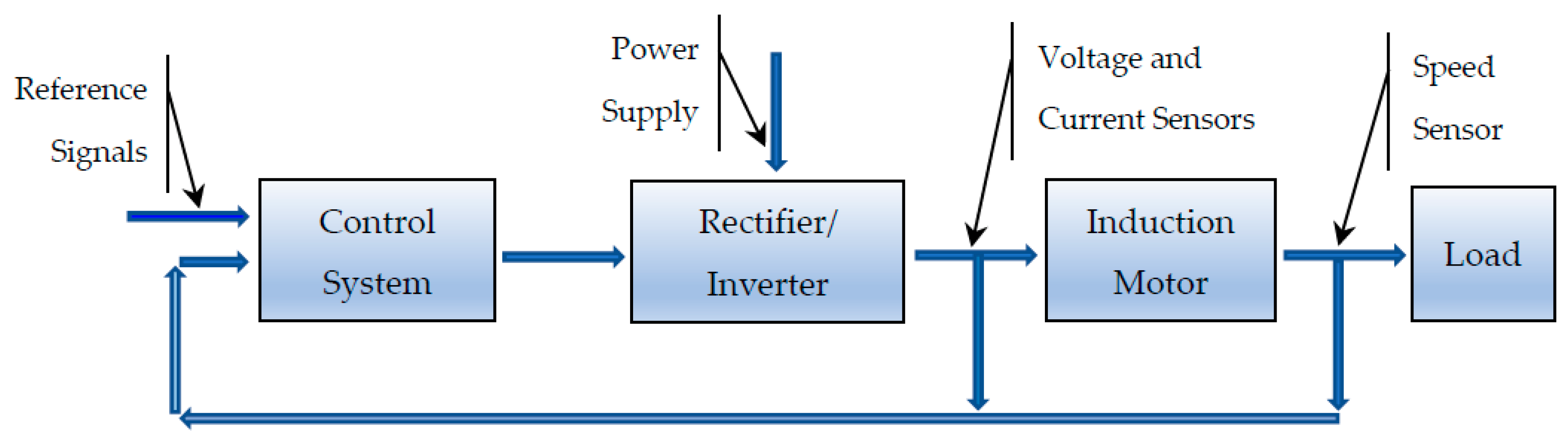
3. Structure of Control System of IM with IoT

In different experiments, induction machines can be installed and run in two operating modes, using similar basic equipment and devices, but organized in different setups and connections: as motors [3,7,50,51,52,53], or as generators [23,37,54,55,56]. The motor operation is preferred for industrial loads, while the generator operation is preferred in WECs [55,56]. In these two different operating modes, the induction machine system changes the initial conditions, reverses the electro-mechanical energy conversion from mechanical to electrical, or from electrical to mechanical, and changes the flow of electrical and mechanical energy between drive system, mechanical, or electrical loads, and power grid. When set as motors, or as generators, the induction machines function with power converters, which can be ac-dc-ac rectifiers-inverters, or ac-ac cycloconverters, connected to three-phase ac networks. In motor operating mode, the three-phase IM systems are working with specific duty cycles [51], with changes in load and speed conditions, or with cut-in and cut-offs [52,53].
The cage IM is a very much used electrical machine in industry. One of the frequent regulation approaches is the scalar control method, or V / f , which maintains constant the ratio voltage/frequency, thereby maintaining constant the air gap magnetic flux. Nevertheless, the electromagnetic flux maintains between stator voltage and stator frequency a rate as in Equation (1) [7,57,58]:
Ψ m = V 1 / f 1 = K 1
where Ψ m is the maximum airgap magnetic flux, V 1 is the maximum stator phase voltage, f 1 is the stator synchronous frequency and K 1 is the ratio of V 1 to f 1 . Nevertheless, for the same IM in different operating conditions, operating points, or duty cycles, the values of V 1 and f 1 can change and, thus, K 1 changes. The basic architecture with block diagrams of the IM scalar control system is shown in Figure 1.
Publications [57,58,59] give descriptions of the performance and limitations of the scalar control applied to IM. The publication [57] is a review article about control and optimization methods for enhancing the performance of IM variable speed drives, such as scalar control operation. However, the accuracy of speed regulation is not significant in open-loop control systems, such as fan, pump, ventilation, air conditioning, etc., [57]. In report [60] is presented an experimental scalar control system for an IM with increased quality of regulation at the operating point of a pressure pipeline and shows the benefits of the high energy efficiency systems. Accordingly, scalar control is a good option for cases of variable speed and variable torque loads.
Our research implements this technique: the control system of the IM connected to the IoT executes remote monitoring over the Internet using sensors to generate data which are feedback and transmitted over the Internet. While carrying out this work, we made the following assumptions:
According to known practices, the study of characteristics of electrical machines can be performed in two separate stages:
(a)
The first stage is the study of the performance in the steady state, at selected operating points, where the functionality and operability of the system must be verified [50,51];
(b)
the second stage is in transient regimes of operation, where different parameters can be instantly changed, and must be verified the operation of the drive, at the same or at different operating points as above. The study of transients implies the study of system stability to instantaneously changes of inputs and of external perturbations [52], the design of controllers [53,54], etc.
Our assumption in the present work is presuming the steady-state operation of the system, without external disturbances of none of the physical inputs. Our primary concern was the operability of the system, the development of hardware and the software, as explained in Section 1. Introduction.
The design part consists of the setting up the laboratory equipment, where the important encountered issues are:
  • The connectivity of equipment with Internet, servers, software, databases and measurement instrumentation. Some of the modules can be connected directly: electric motors, power converters, microcontrollers, and sensors. Other modules are connected indirectly by using a gateway for the communication with the backend system, which provides device registration, data collection, data analysis and processing, logical design and visualization;
  • The data acquisition, conversion, storage, retrieving, analysis, computations. Other tasks for data processing are real-time visualizing, sending to monitoring system, etc.
The block diagram of the experimental control system of the IM with IoT is shown in Figure 2.
The system depicted in Figure 2 can be configured and set to operate in three modes:
  • Control system with IoT, with stator variable-voltage-variable-frequency, for variable load-variable speed operation, with feedback for speed and for load current. The IM is fed by the inverter, drives the dc generator, and the dc current supplies an electric load. The SBC and SBM1-SBM2 are receiving data and sending commands by using the IoT to control the inverter’s output variable frequency;
  • Open-loop control system without IoT, with stator variable-voltage-variable-frequency for variable load-variable speed operation, and without feedback. The IM is fed by the inverter in local control mode, drives the dc generator which supplies an electric load. The SBC, SBM1-SBM2 and the networks with the IoT are disabled;
  • The typical constant speed operation. The IM receives the 3-phase constant voltage-constant frequency, drives the dc generator and supplies the electric load.
The configuration (2) results from the configuration (1) by disabling the software, the speed and load current feedback and the Internet. Operation with configuration (3) can be obtained when the control system is removed.

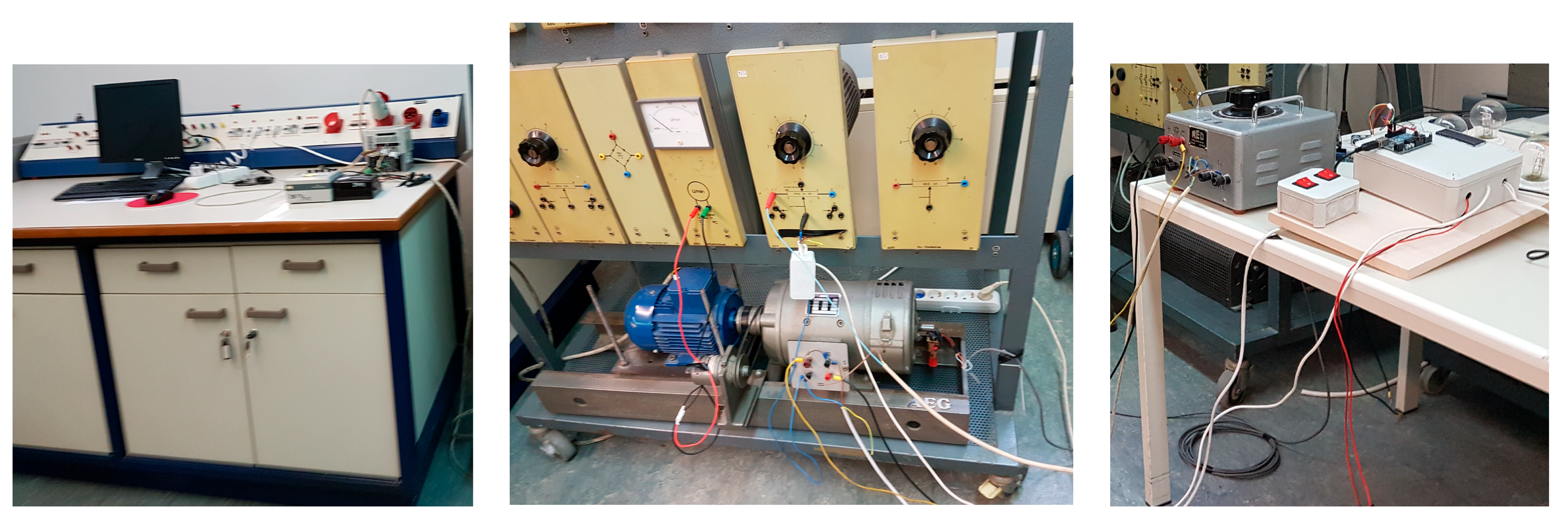
4. Hardware Structure and Modules

The experimental system has the structure and modules shown in Figure 2. This experimental configuration implements the remote control of a three-phase IM with IoT using one rectifier-inverter [61], two microcontrollers SBM1 and SBM2 [9], one SBC [10], a structured query language SQL for storing, manipulating and retrieving data in the database and a web application (Web-App) on Azure cloud platform [62,63], stored on the server and delivered over the Internet through IM Control Web interface. The hardware units, components of equipment, and modules are described below and shown in Figure 3, Figure 4, Figure 5, Figure 6, Figure 7, Figure 8 and Figure 9.
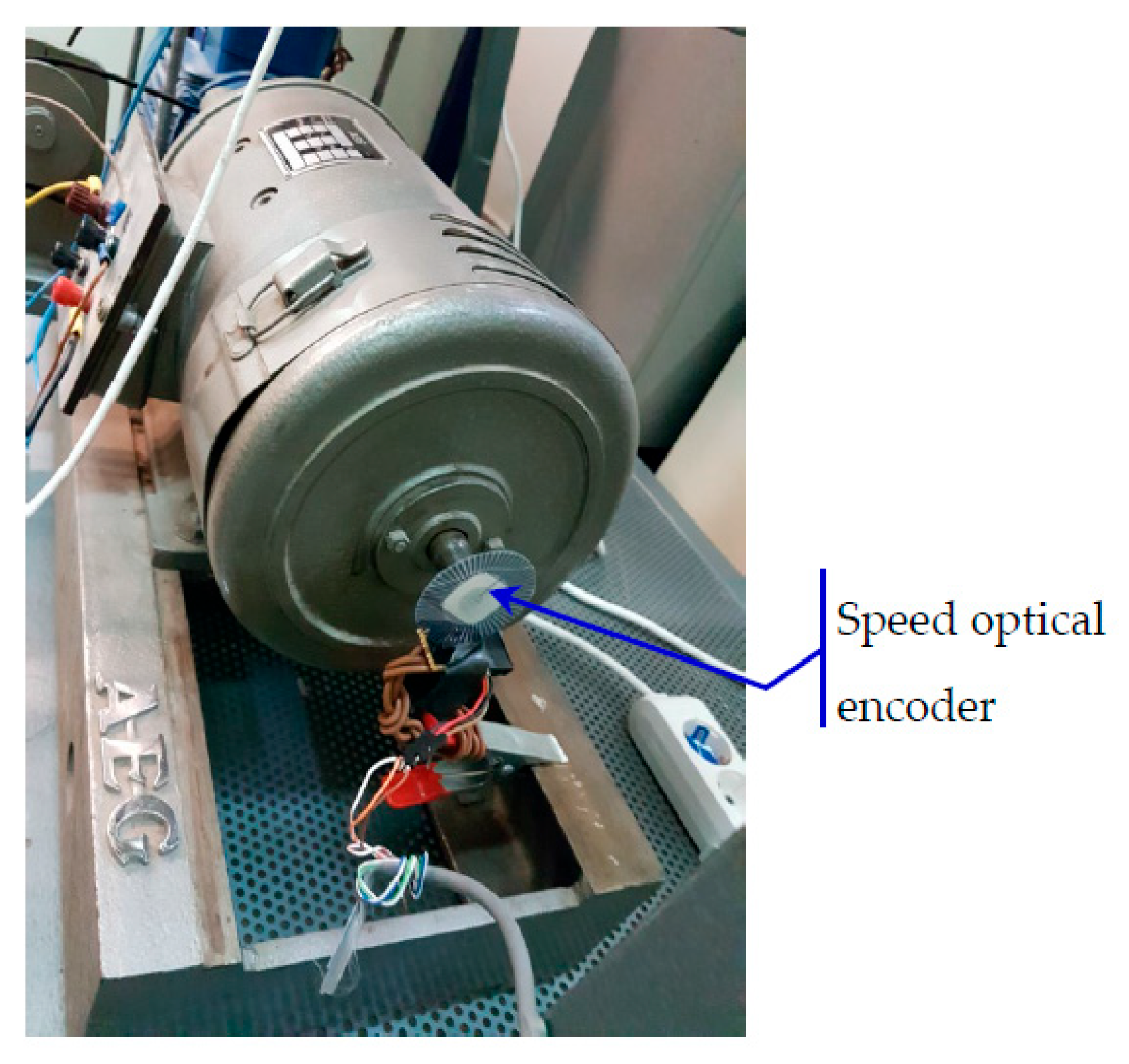
  • The electrical machines and drive modules, Figure 3:
    • One IM is connected to a dc generator and supplies an electric load;
    • One digitally controlled three-phase rectifier-inverter with keyboard and programmable [61];
    • One single-phase rectifier, which supplies excitation voltage to dc generator;
    • Variable electric loads.
  • The Control System Units, Figure 4 and Figure 5:
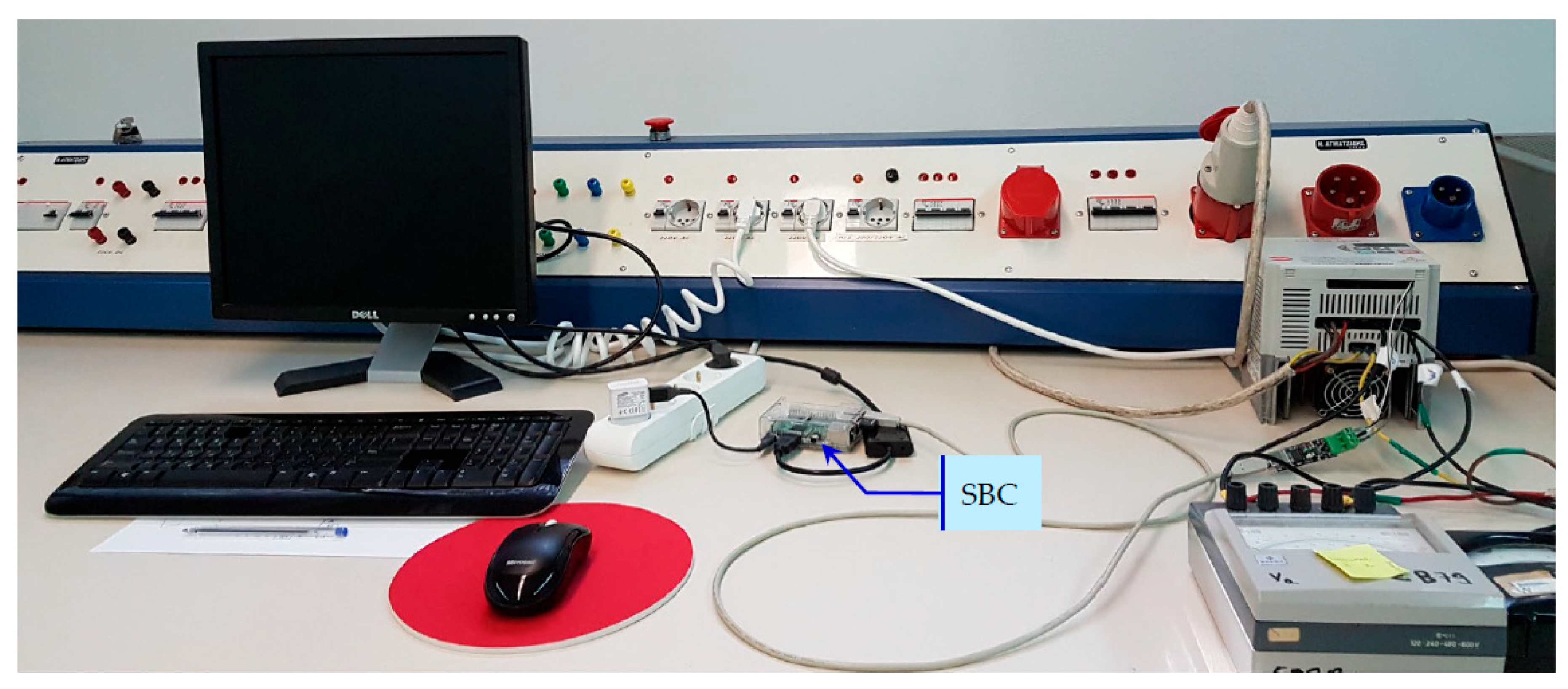
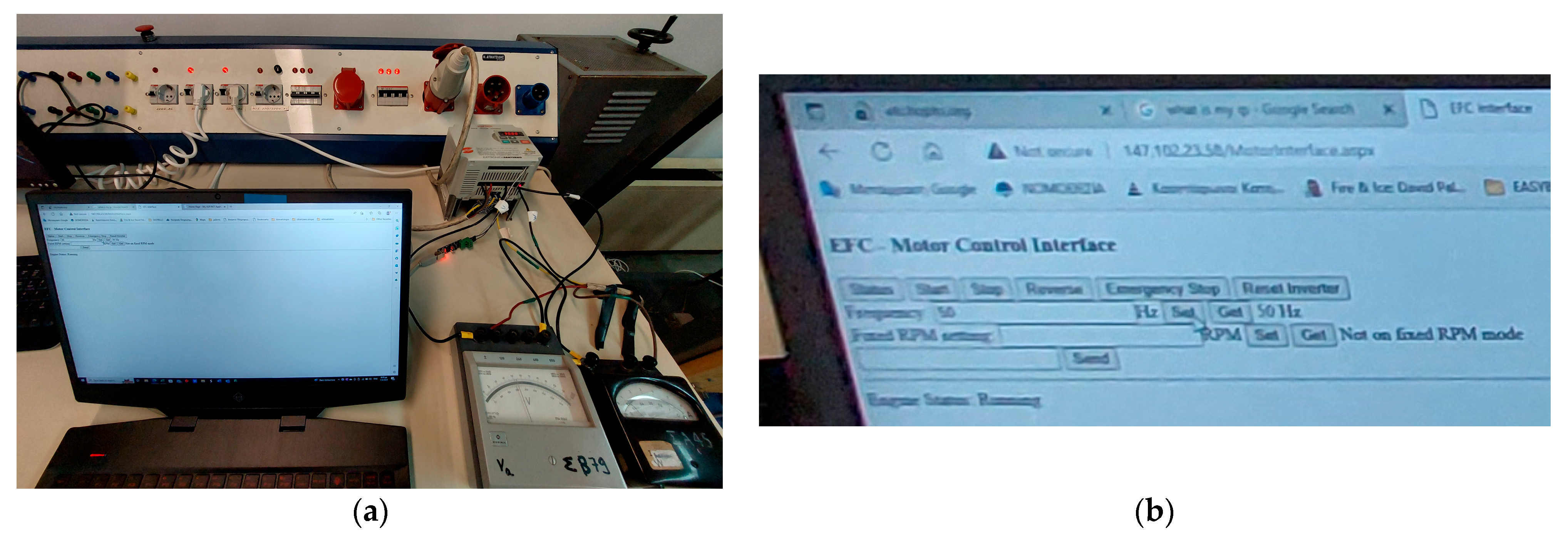
    • One IM Control Web Interface, Figure 5a,b;
    • One SBC [10], which has the role of local server, linked to the rectifier-inverter and controls IM stator frequency. The SBC, (Figure 3 and Figure 4), acquires data from sensors through SBM1 and SBM2 [9] (Figure 3, Figure 7 and Figure 8);
    • Software for the control of IM with IoT;
    • Web application (web app) on Azure cloud platform, links with the SBC to distant control, for storage and data processing;
    • One Supervisory Computer, and smart phones, with access to the IM Control Web Page, shown in Figure 3, Figure 4 and Figure 5;
    • The installation is connected to a central control panel, equipped with start key, and emergency stop push button for manual control, (Figure 3, Figure 4 and Figure 5).
  • Networks:
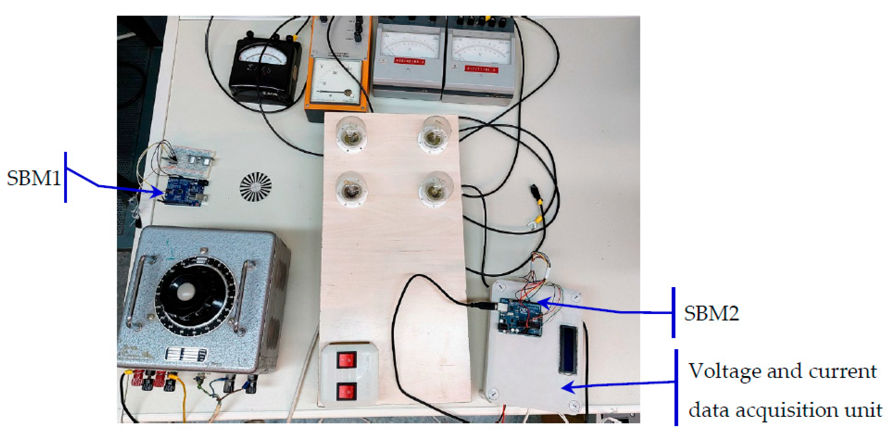
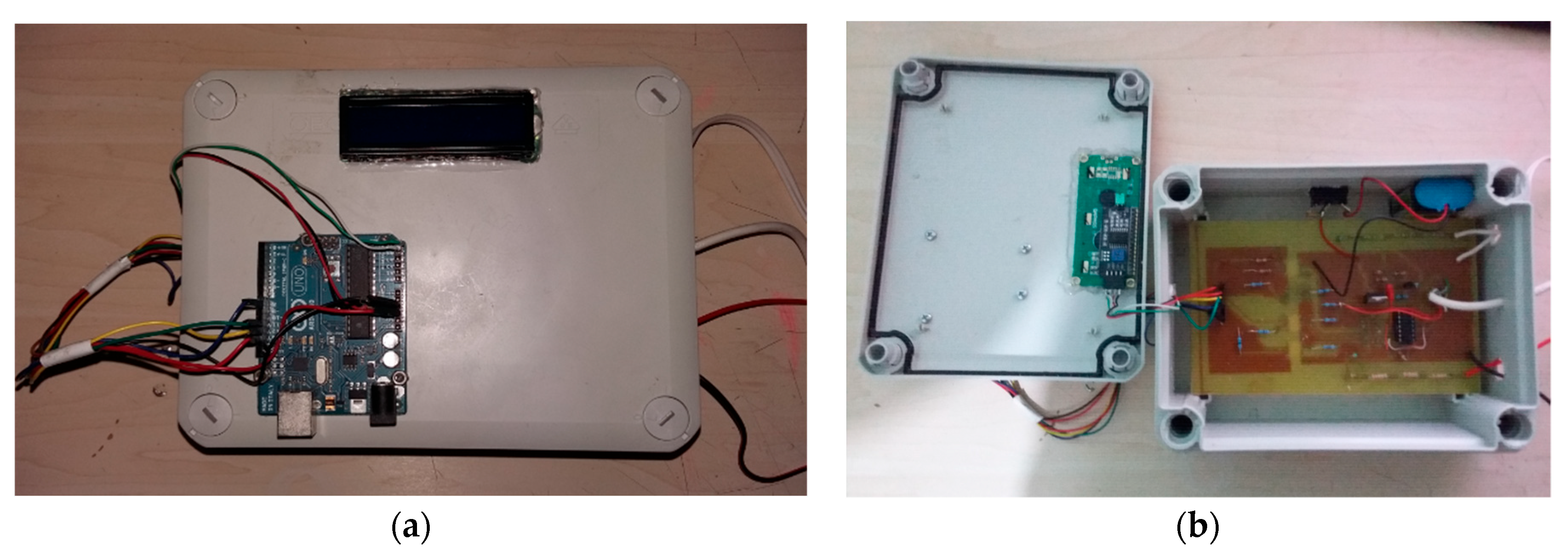
  • Data Acquisition Units
    • A Speed Optical Encoder for measurements of angular speed of the IM. It transmits data to SBM1, shown in Figure 6;
    • An Optical Isolation Unit between power modules, digital-electronic-control units, and sensors modules. It is designed to protect the sensors’ microelectronics from industrial voltages, and transmits data to SBM2, shown in Figure 7 and Figure 8;
    • Other measuring instruments for voltages, frequencies, currents, and speed. The block diagram of measuring system is shown in Figure 9.
For the measurements of currents, and voltages, an electronic board with Opto-Isolation has been in-house designed and constructed, to separate power modules from microcontroller SBM2 [64]. The SBM2 implements the data acquisition from the True RMS Current Hall Sensor, and True RMS Voltage Sensors (optically isolated) of electric load. Then, it displays data, and transmits data to SBC via Bluetooth [64]. The optical isolation unit and the data acquisition unit can be seen in Figure 7 and Figure 8a,b.
The data acquisition system consisted of a measurement device that includes a microcomputer with integrated circuits for analog to digital signal conversion (ADC). As input, we have the sensors for:
(a)
voltage, is measured by using a resistive voltage divider to scale down DC Voltage;
(b)
current, is measured with the use of a Hall sensor (linear Hall sensor ACS714ELCTR-05B-T) [65].
The next stage is an amplifier-isolator (Optoisolator 6n137) [66], to convert the signal to the full dynamic input range for the ADC (MCP3008 integrated circuit), which gives its result in binary digital output [67].
The microcontroller SBM2 then records this digital output and performs digital processing to finally provide the measurement for display or further processing. The measurement devices were built as thesis projects in the laboratory and checked for the validity of their results [64].
The 3-phase voltage 380 V/ 50 Hz supplies the 3-phase central control panel, equipped with main switches, isolation transformers, emergency stop push button, start key, which provides protection to the entire experiment against over-currents, voltage discharges, short-circuits, or other hazards, shown in Figure 3, Figure 4 and Figure 5.
The experimental control system was implemented and tested for the cage rotor IM, which has the technical data 0.75 kW, 400 V, 50 Hz, 1.9 A, 1390 rpm, 4 poles, and power factor 0.76, [68]. The IM has the shaft connected to a dc generator, which has the technical data 0.5 kW, 220 V, 3.2 A, 1500 rpm and supplies a load in the range 0 ÷ 150 Ω.
The 3-phase rectifier converts the 3-phase voltage to dc input to the inverter. The inverter converts the dc voltage to 3-phase voltage output, and supplies it to the windings of the stator of the IM. At the same time, the inverter is linked to the SBC. The 3-phase rectifier-inverter, model Vega Drive 4T002BIK for 0.75 kW motor, has the technical data: input 380 V÷460 V, 50/60 Hz, 3 A, output 0÷input V, 0÷400 Hz, 2.5 A, 1.9 kVA, [61]. One single-phase rectifier with the technical characteristics 1.5 kVA, input voltage 0 ÷ 220 V, 50/60 Hz, output voltage 0÷250 Vdc, output current 6 A, supplies the dc excitation voltage to the dc generator.
The single-board microcontrollers SBM1-SBM2, model ATMega2560, have the technical data: 54 digital I/O pins (15 provide PWM output), 16 analog input pins, 256 kB flash memory of which 8 kB used by bootloader,8 kB SRAM, 4 kB EEPROM, [9]. The single-board computer SBC has the technical data: CPU 4xARM Cortex-A53, 1.2 GHz, 64-bit quad-core, GPU Broadcom VideoCore IV, 1 GB RAM, microSD storage, 10/100 Ethernet, 2.4 GHz, 802.11 n wireless LAN, Bluetooth 4.1 Classic, Bluetooth Low Energy (BLE), ports HDMI, 4xUSB 2.0, Ethernet, Camera Serial Interface (CSI), Display Serial Interface (DSI), SoC Broadcom BCM2837, [10].
The remote-control system of the IM over the Internet, with the IM Control Interface and with the SBC, sends commands to the inverter, Figure 3, Figure 4 and Figure 5. Specifically, the inverter follows the Modbus protocol, which connects industrial electronic devices to the network [69,70]. The messaging structure of modbus protocol is implemented using the adapter USB-RS485.
The modbus protocol has master–slave roles: a message from the master to the slave device is sent to the address of the slave and contains the ‘read register’ or the ‘write register’, the data, and the check sum [63,69]. The data contain the information that the slave needs to perform the function: which register to start, how many registers to read and the error check sum validates the integrity of the message. The error check permits the master device to confirm that the messages is valid. If an error occurs, the function code indicates that the response is an error response. If the slave makes a normal response, the function code in the response is an echo of the function code in the request and the data bytes contain the data collected by the slave.
The controller communicates on modbus network using transmission mode of SBC. This microprocessor-based system controller is implemented with hardware and software external modules and devices: the speed sensor for the speed feedback, the current sensor is used for the load current feedback [53]. The speed optical encoder (Figure 6), is interfaced to SBM1 and executes the speed sensing and measurements.

5. Software Description

The software run in the supervisory computer using the IM-Control Web Interface, which can be accessed using the static IP address reserved for laboratory experiments.
The programmed operation modes into the driving system are the following commands: Status, Start, Stop, Reverse Direction, Emergency Stop, Reset Inverter, Set Required Frequency, Send Frequency to system, Read Real Frequency from system (Figure 5a,b). The Required Frequency is displayed at the IM-Control Web Interface. Also, the display shows the Real Frequency computed from the feedback signal.
There is a common engine interface, which consists of an engine class of transmitted messages. They are accessed in asp.net platform [71,72] using web application controller (asp.net web apps), which receives commands from the IM-Control Web Interface.
From the IM-Control Web Interface, the operator selects the Set Required Frequency command for the forward rotation or selects Reverse Direction command for the backward rotation. Then, by selecting Start command, the IM begins rotation. When Stop command is selected, the rotation stops. The inverter is controlled by the software to execute a required constant frequency command.
The SBM2 receives the feedback from the current sensor of the dc generator armature. The SBM1 receives the feedback from the speed optical encoder. Both SBM1 and SBM2 send acquired signals to the SBC software by using the Bluetooth connection, (Figure 6, Figure 7, Figure 8 and Figure 9). The SBC reads the Required Frequency and the Real Frequency of the IM. The difference between the Required Frequency by the operator and the Real Frequency computed from the rotational frequency of the IM generates an error signal: if it is positive, or negative, then the SBC decreases or increases, respectively, the frequency of the inverter and, the resulting control signal is sent from the SBC to the inverter to correct frequency.
The software code that controls the inverter is in language C#.

5.1. Monitoring and Protection Software

The IM was connected to varying loads. The steady-state line voltages, frequencies, phase currents, and rotational speeds were measured at the IM stator side. Also, at each steady-state operating point, determined by the load, the voltages, and currents were measured at the dc generator load side.
For IM to reverse direction of rotation, must be selected the Stop command from the IM Control Webpage. Also, for protection against overcurrent during starting or loading, there are programmed commands as inputs to IM control Webpage and to SBC:
  • Forward or backward command;
  • Set Required Frequency setpoint command;
  • At no-load, if the Required Frequency setpoint is lower than 10 Hz or 20% (0.2 per unit) of the nominal frequency, the IM is not starting;
  • At higher loads than 40% (0.4 per unit) of nominal current and a Required Frequency setpoint lower than 20 Hz or 40% (0.4 per unit) of the nominal frequency, the IM is not starting;
  • In overloading situations, at higher loads than 100% of the nominal power and if the Required Frequency setpoint exceeds 100% of the rated frequency, the IM enters the cut-off Emergency Stop process and the IM is cut-off. The operator must select the Emergency Stop command, remove the load and decrease the frequency. Following this, the IM can be restarted.
During the present experiment, if the Internet connection is lost, the IM will maintain its last state of operation until any further manual on-site command is given to the inverter. At the moment, in the IM Control Web Interface there is a command button for Emergency Stop. This corresponds to operating mode (2), as described in Section 3.
The system for the time being executes the commands on a “first come, first served” basis, regardless its user origin. However, because the users belong to the group of students and researchers of the Laboratory of Electric Drives of the National Technical University of Athens (NTUA), they are authenticated as authorized users by the NTUA Network Operation System NOC servers.
There is an option for future expansion in the web application, to assign user roles each one with privileges, that will enable users to perform certain actions and determine priority of the execution of commands and set any other desirable permissions. This option comes under Authentication and Authorization (Figure 10). The users must be registered, authenticated, and have distinct hierarchized roles such as: Administrator, High Priority User, Low Priority User, Visitor.

5.2. Operation Software

Initially, the IM is connected to the 3-phase voltage 380 V/50 Hz and starts without load. The Rectifier-Inverter, connected to the same network, converts the ac to dc voltage, and then to ac variable-voltage-variable-frequency, drives the IM and controls its speed. Subsequently, the IM is loaded and the rotation is transmitted to the shaft of the dc generator, which receives excitation voltage from the single-phase rectifier, generates dc voltage and supplies the load, (Figure 2 and Figure 3).
The supervisory computer, or a smartphone, connects to the IM-Control Web Interface and from here, to the remote system of the rectifier-inverter by using modbus protocol (Figure 5a,b). The rectifier-inverter connects to the SBC by an adapter USB-RS485. The connection is opened and controlled in asp.net platform environment [72], by using the modbus protocol library [69,70,71].
Without web control, the reference signals and the commands to the inverter can be entered using inverter’s keyboard. To activate the web control for the inverter, are selected the function DRV-03 associated with the modbus protocol and the function DRV-04 associated with the frequency. The communication between supervisory computer and inverter is master–slave.
When using the IM Control Web Interface, the inverter is commanded by the supervisory computer, or a smart phone, with Internet connection, Figure 4 and Figure 5, while the other local handling from the inverter’s keyboard are disabled.
The SBC connected to a monitor, keyboard and mouse is the local server. All measured data acquired are stored to the SQL database, located in Azure cloud [62].
The link of the speed optical encoder to the remote system is executed by the SBM1, which transmits the measured data through Bluetooth to the SBC, Figure 6 and Figure 7. The SBC using an Application Programming Interface (API) of the web application on Azure, uploads the data in the SQL database.

6. Results and Discussion

The IM system with IoT, while the SBC supervises the process, was experimentally tested and loaded. During operation the software correlates the parameters.
Figure 11, Figure 12, Figure 13 and Figure 14 present the steady-state characteristics of the output torque, power and efficiency vs. rotational frequency, for three frequency commands generated by SBC for the inverter, at 35 Hz, 50 Hz, and 65 Hz. The characteristics were measured by changing the load in discrete steps, as shown by the marks in each one of the Figure 11, Figure 12, Figure 13 and Figure 14. The variations of loads were considered and studied in the steady state operation, and the system presented a stable steady state behavior.
Consequently, we decided that for such kind of load variations is not necessary the study of transient behavior. Thus, the transient phenomena were not recorded, and not measured during the described experiments. Also, were not studied sudden changes in control commands of voltage and frequency supplied by inverter which could lead to transient behavior of the system.
For reference purposes, the performance of IM supplied from the central control panel with 3-phase voltage 380 V/50 Hz was measured, according to operation mode (3) (Section 3). Then, the IM with IoT control experimental system was operated from no load to full load (1.0 per unit), according to operation mode (a) IM with IoT control (Section 3). The ranges of torque and speed are according to the design of hardware and software, (Section 4 and Section 5).
The following method was applied for the computations of results.
The torque T is computed from the mechanical power P and rotational speed ω according to Equation (2) and is shown together with the output power in the same rotating frequency range, in Figure 11, Figure 12 and Figure 13.
T = P / ω
Theoretically, by neglecting the magnetizing current, an approximate value for the efficiency E f f of the system can be computed from the Equation (3):
E f f = P o u t / P i n
where P i n is the active power input to the system (in watts) and P o u t is the active power output from the system (in watts). In the laboratory experimental system, from measured voltages and currents is computed the output power.
The mechanical power P from Equation (2) and the active power P o u t from Equation (3) are considered as equivalent to the output power of the IM. They are obtained from measurements of voltages and currents, at the field winding and armature winding of the dc generator (Figure 2). The field winding is not shown in the block diagram from Figure 2 for reasons of simplifying the picture, but the windings’ terminals can be accessed at the motor terminals box with connectors, shown in Figure 3 and Figure 6.
The generated dc voltage is measured by using a voltmeter at different values of load resistance between 40 Ω–135 Ω, and different values of excitation voltage of the dc generator. The field current values have been measured at the dc generator field winding, by using an ammeter; similarly, the armature currents have been measured at the dc generator armature windings, by using a second ammeter, Figure 7.
The balance of active powers in the motor-generator system is:
P i n P I M , l o s s + P d c , f i e l d P d c , l o s s = P o u t
where P d c , f i e l d is the excitation watts for the dc generator, and P I M , l o s s , P d c , l o s s are the losses of the induction motor and of the dc generator, respectively. Both machine losses can be determined from laboratory tests run in configuration mode (3).
The output active power is calculated at the dc load side by using Equation (5):
P o u t = V d c I d c
where V d c and I d c are the voltage and current at the dc generator terminals.
Also, Equations (6) and (7) are given below to explain the calculations for establishing the measured characteristics of the rotational frequency in Figure 11, Figure 12, Figure 13 and Figure 14.
ω 1 = 4 π f 1 p
ω = ( 1 s ) ω 1
where f 1 is the synchronous frequency (in Hz), p is the number of poles, ω 1 is the synchronous angular frequency (in rad/s) and s is the slip of the IM.
Some measured characteristics during operation are shown in Figure 11, Figure 12, Figure 13 and Figure 14, which present the measured output torque, mechanical power and efficiency vs. rotational frequency, for the three frequency commands generated by SBC for inverter: subsynchronous 35 Hz, synchronous 50 Hz, and supersynchronous 65 Hz.
We tested the system in the two configuration modes (1) with IoT control, and (2) with local control, and the obtained results over a range of ±30% of the nominal frequency show a good correlation. The torque and mechanical power characteristics vs. rotational frequency were studied for the rotational frequency range 0.7 per unit to 1.3 per unit of the synchronous frequency, corresponding to three frequency commands to the inverter: subsynchronous 35 Hz, synchronous 50 Hz, and supersynchronous 65 Hz, respectively, illustrated in Figure 11, Figure 12 and Figure 13, respectively. The obtained results show that configuration mode (1) functions with varying rotational frequency-varying torque in the speed range from 1050 r/min up to 1950 r/min, and from zero up to 85% (0.85 per unit) of the rated loads. Then, the efficiency for varying values of rotational frequency was obtained.
Usually, efficiency is one index of performance that must be estimated in system operation and it is important for large power ratings of IMs, where few percent correspond to significant amounts of energy. In the study case of the described IoT controlled IM, the efficiency was estimated according to Equations (3)–(5). It is usually considered that a comparison with other known or previously published similar systems could give an estimation about the eventual improvements of the new proposed and described drive system in this manuscript. We searched the literature for related publications on IoT controlled IM with a similar configuration and ratings, which give detailed numerical results about the performance, and we did not retrieve such details. For this reason, we decided to make a comparison with a study case of an IM controlled by PLCs in local mode, and without Internet, as reported in publication [3]. The efficiency is computed in per unit (not in percent) considering as base value the ratings of each IM.
In Figure 14, the efficiency is normalized, taking as 1 per unit the efficiency of the IM working with the 3-phase power grid, configuration mode (3) (Section 3). As depicted in Figure 14, the results show that the system with IoT has increased efficiency at supersynchronous rotational frequency.
The obtained increased efficiency at supersynchronous speeds can be justified by:
  • the hardware modifications which consist mainly on replacing the PLC modular wired components (CPU, motherboard, analog inputs-outputs, relays, multiplexers, power supply), by software with high computing capabilities of server, data storage and processing using mathematical models and cloud applications;
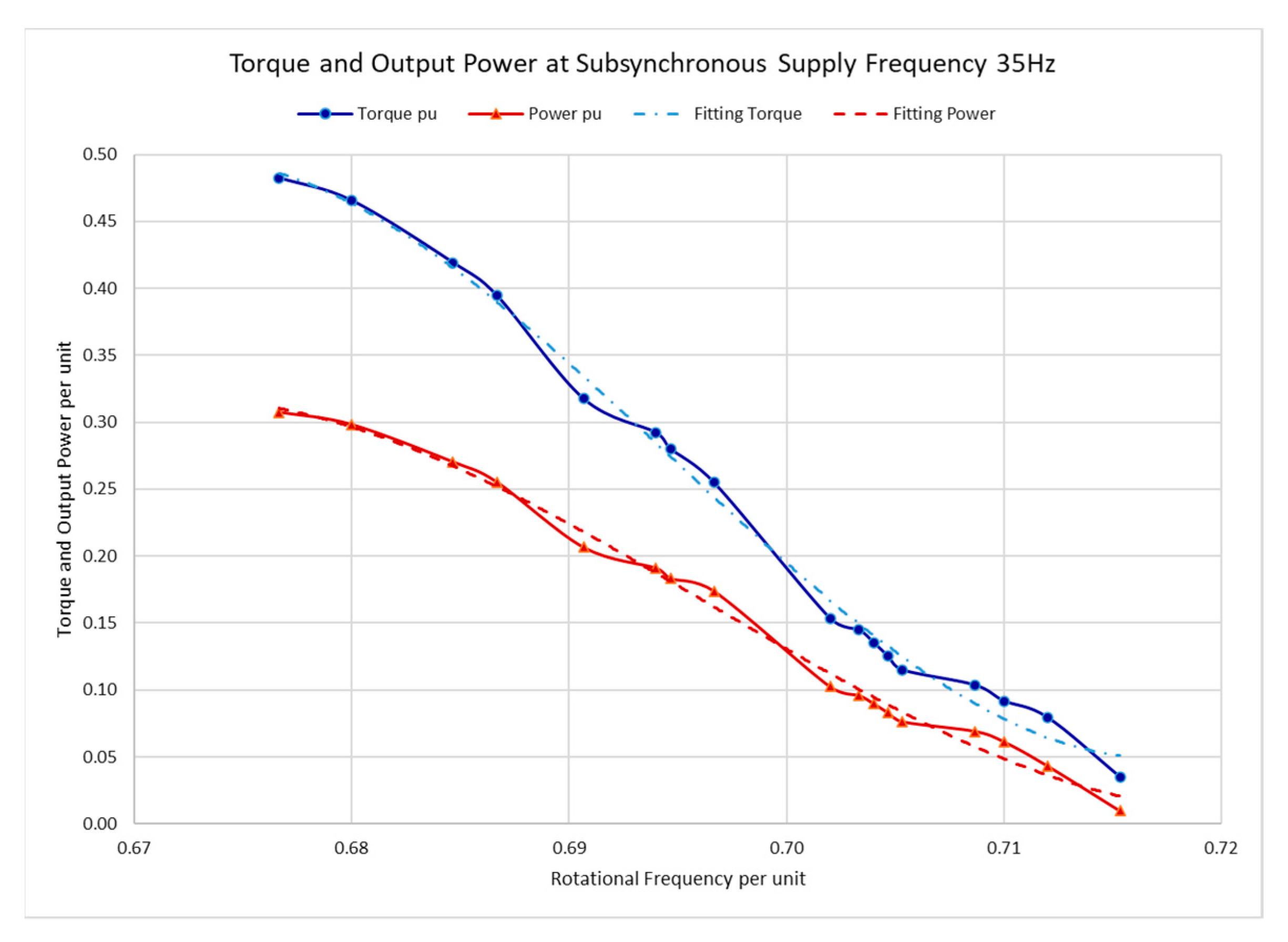
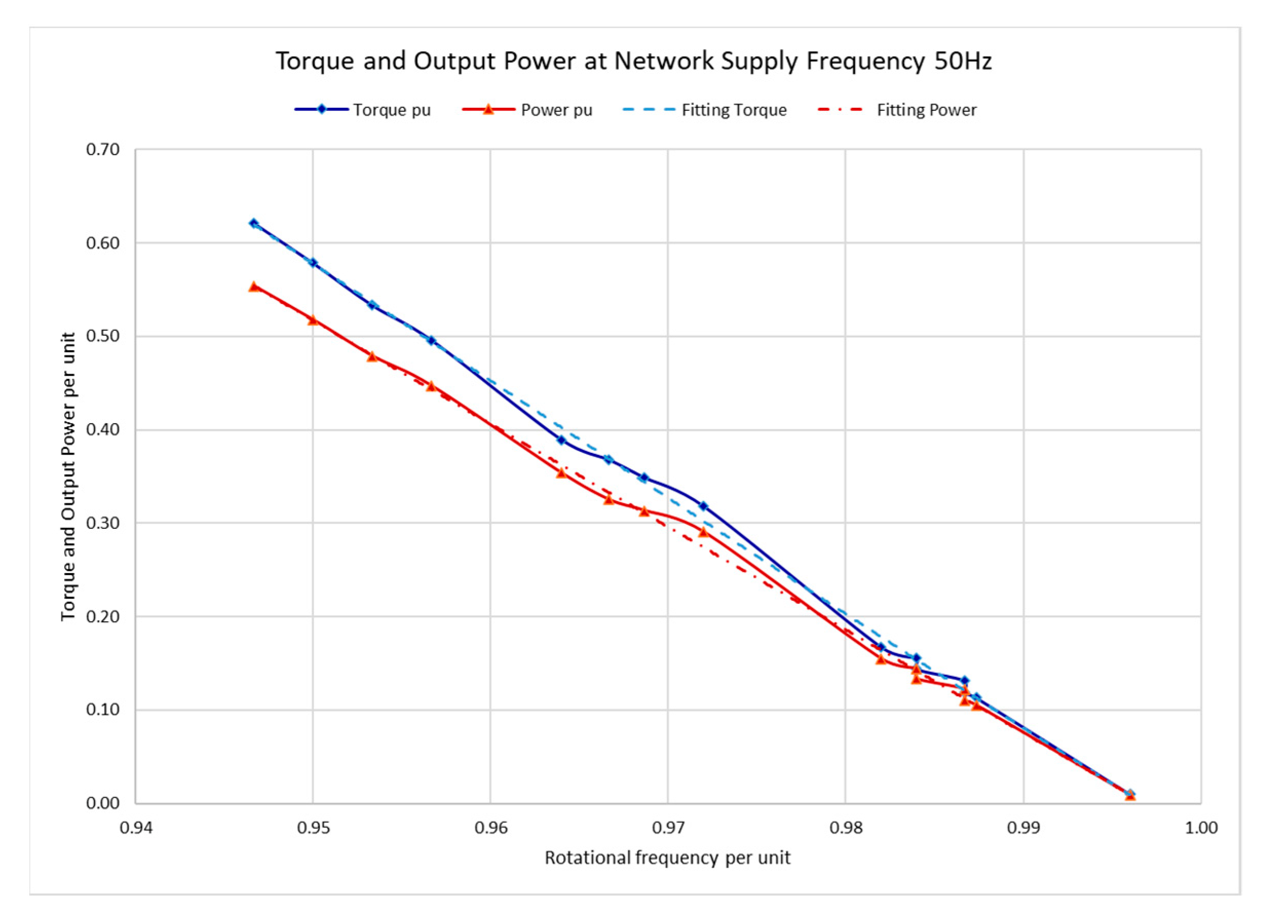
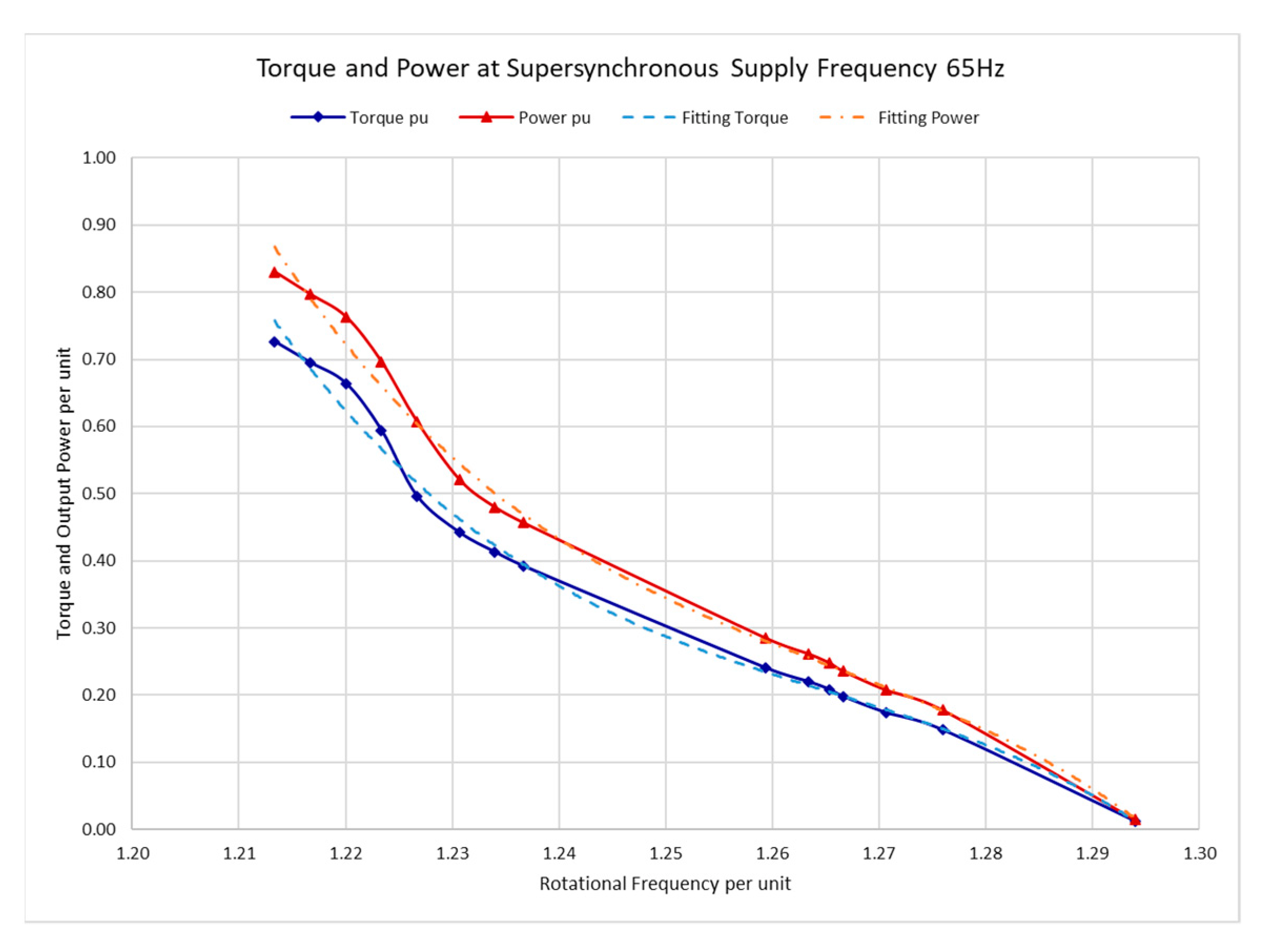
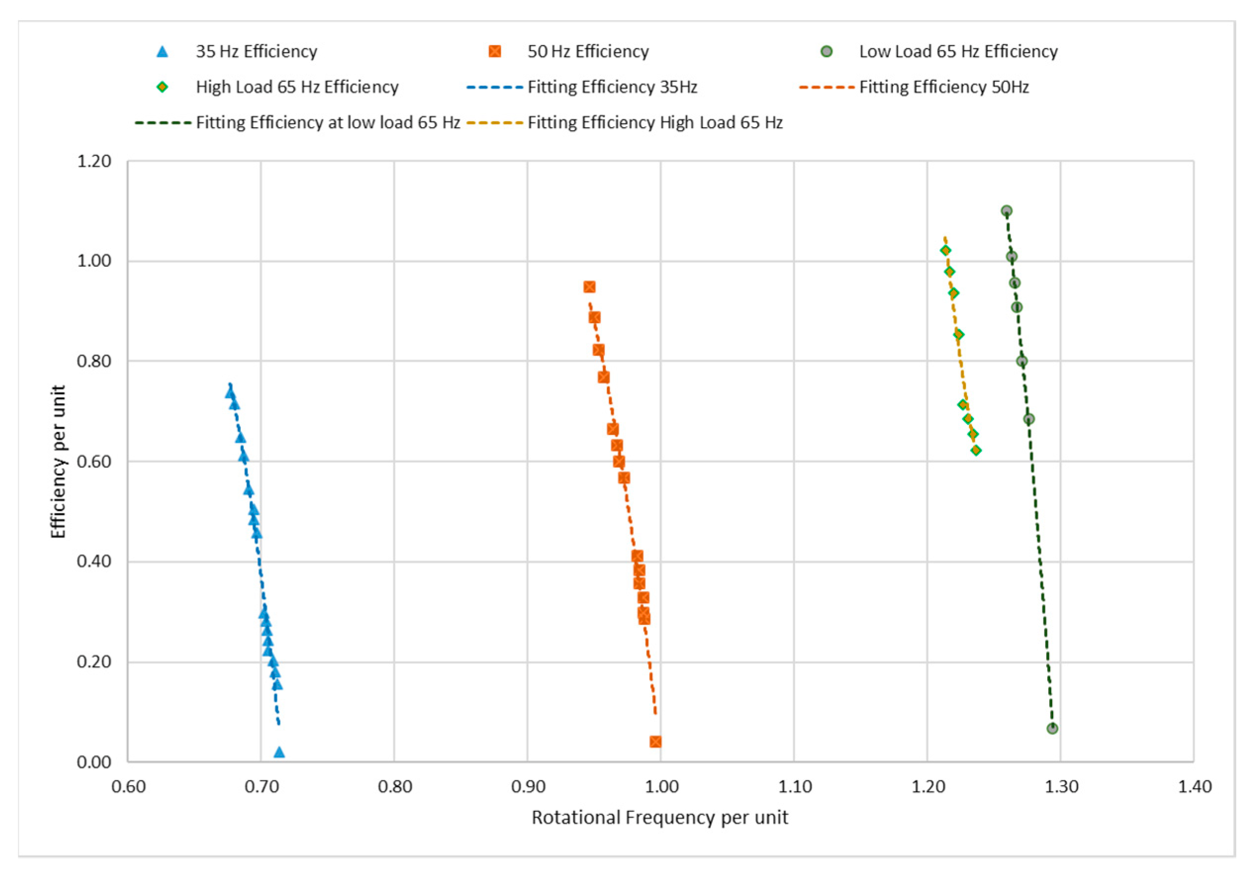
  • at supersynchronous speeds higher than 1500 r/min the amount of power input and output are increased as compared to the rated values of the drive, thus it is obtained a better utilization of the design and construction of the same IM;
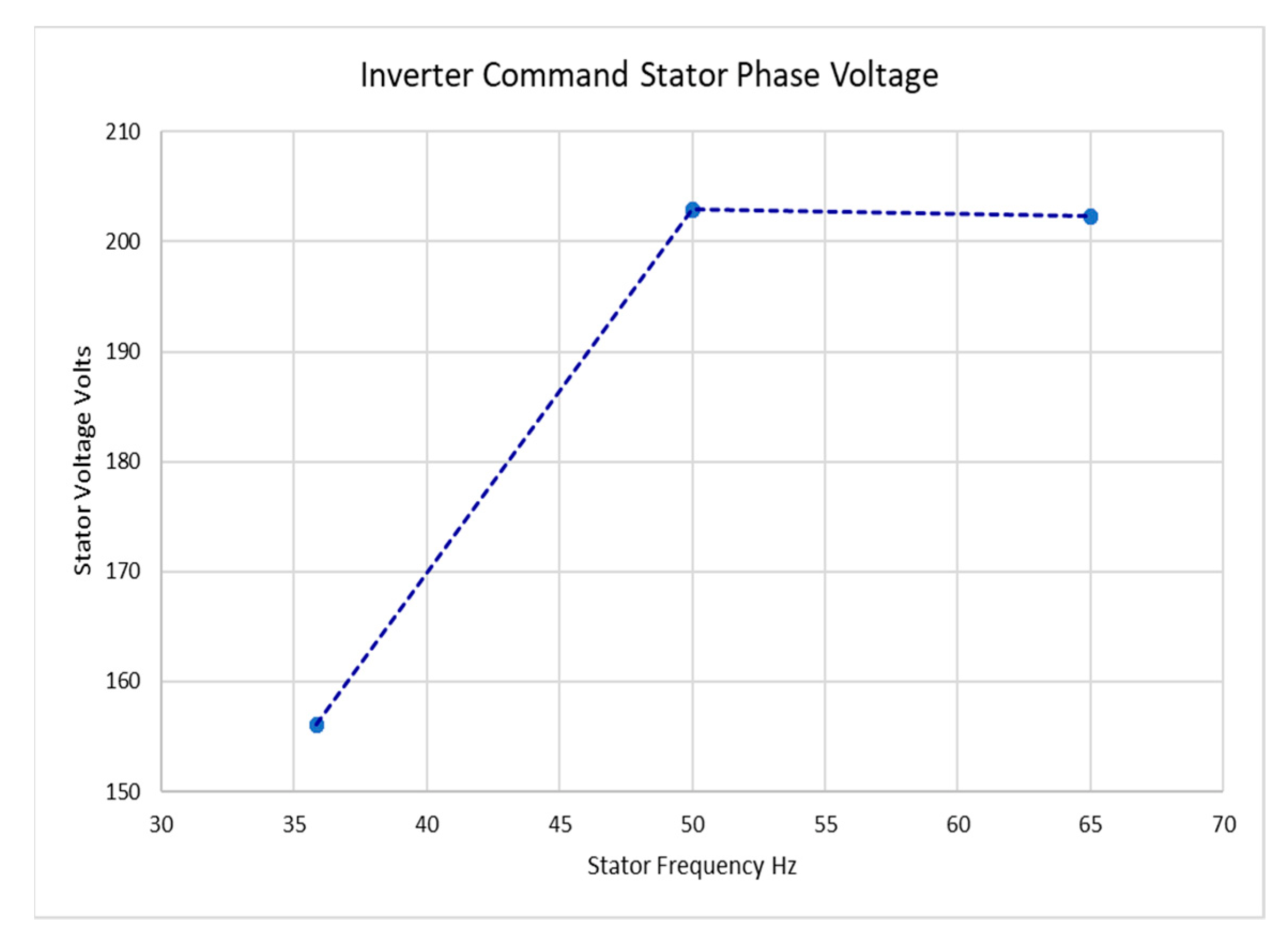
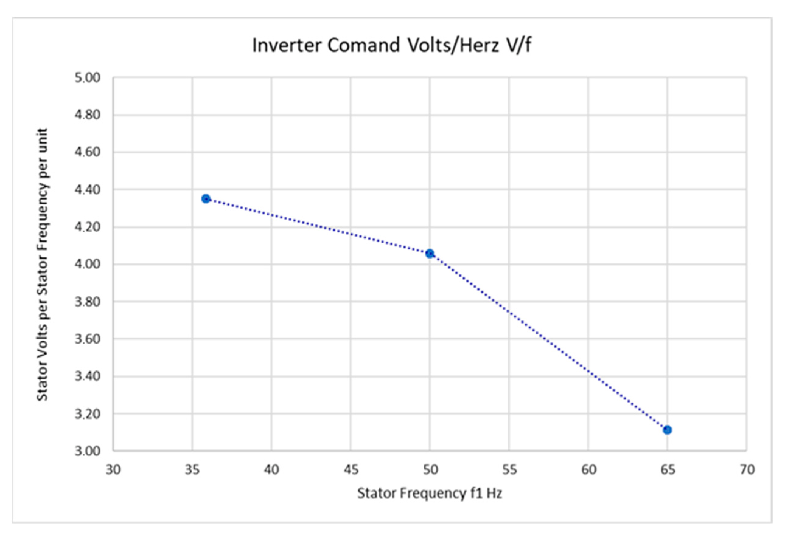
  • at supersynchronous speeds, which corresponds to higher than the rated supply frequencies, the magnetizing field produces lower magnetic loses. In such situations the relation between voltage and frequency is kept constant as in Figure 15, from 50 Hz to 65 Hz. The ratio voltage per frequency at 65 Hz from Equation (1) is lower than in the situations at 50 Hz, and 35 Hz, Figure 16.
Also, because at higher than 70% loads, the efficiency increases, the results indicate that by using IoT control which monitors the current, higher overall efficiency can be achieved than in the case of an IM without IoT. According to this, in Figure 14 it is shown that the efficiency of IoT-controlled system can increase up to 10%, as compared to the standard operation. Also, from Figure 14 can be seen that, at high speeds and frequencies, the IoT-controlled system acquires low slip values and produces low amounts of slip power at the rotor, and, thus, the increased values of efficiency are justified [50,51]. At low frequencies, the magnetic flux increases and, thus, increases the magnetizing current and magnetic losses.
Figure 15 shows the characteristics of stator voltage vs. stator frequency with IoT control for the same corresponding range of frequencies, torques and powers as in Figure 11, Figure 12 and Figure 13. For the operating points torque-rotating frequency (Figure 11, Figure 12 and Figure 13), the relationships stator voltage-stator frequency is constant. However, according to Equation (1), this relationship corresponds to the motor flux, decreases with the increase of frequency from 4.35 at 35 Hz, to 4.05 at 50 Hz and to 3.11 at 65 Hz, (Figure 16). Thus, when frequency increases, the rate of V / f decreases from 4.35 per unit at 35 Hz up to 3.11 per unit at 65 Hz (Figure 16). At frequencies lower than synchronous, from 35 Hz up to 50 Hz, there is a linear increase of volts vs. hertz. At frequencies higher than 50 Hz, up to 65 Hz, the stator voltage remains constant.

7. Conclusions

The paper presented the experiments from an integrated control system of an IM electric drive using IoT technology. With existing components of hardware and inhouse-developed new software and new hardware modules, the academic Laboratory of Electric Drives was retrofitted and updated to control drive systems with the new technology of IoT. The obtained experimental results from the described control system were successful, indicating that the IoT can be introduced in automatic systems with IMs. The system of the IM controlled by IoT provides high accuracy in speed control at variable loads.
This system achieved controlled speed for successive load changes, full torque over a wide speed range, good accuracy and high efficiency. The effectiveness of the IoT-based control software is satisfactory at both subsynchronous and supersynchronous rotational frequency. The efficiency of the IoT control was increased as compared to the local control and, specifically, at supersynchronous frequencies, high rotational speeds and low values of slip.
Thus, the IoT was demonstrated to be an appropriate control tool in industrial installations with IMs. Also, experiments similar to the one described above can be widely implemented for engineering students and researchers working on Internet-based projects. The students and researchers can develop new modules of software and hardware, then can experiment with changing operational conditions, based on a main IM system integrated with IoT and changing remote devices connected to Internet.
The study of transient behavior of IoT control of IM drive system can be a continuing topic for this research.

Author Contributions

Conceptualization, A.P.S. and M.G.I.; methodology, A.P.S., S.A.P., E.B.K. and M.G.I.; software, A.P., V.V., N.A., A.P.S., S.A.P. and E.B.K.; validation, A.P.S., S.A.P. and E.B.K.; formal analysis, E.E.S. and M.E.S.; investigation, E.E.S. and M.E.S.; resources, A.P.S., S.A.P. and M.G.I.; writing—original draft preparation, S.A.P. and M.G.I.; writing—review and editing, A.P.S., S.A.P. and M.G.I.; supervision, E.B.K. and M.G.I.; project administration, M.G.I.; funding acquisition, M.G.I. All authors have read and agreed to the published version of the manuscript.

Funding

This research was funded by National Technical University of Athens, Research Committee, grant number 95002900.

Data Availability Statement

Not applicable.

Conflicts of Interest

The authors declare no conflict of interest.

References

  1. Sengamalai, U.; Anbazhagan, G.; Thamizh Thentral, T.M.; Vishnuram, P.; Khurshaid, T.; Kamel, S. Three Phase Induction Motor Drive: A Systematic Review on Dynamic Modeling, Parameter Estimation, and Control Schemes. Energies 2022, 15, 8260. [Google Scholar] [CrossRef]
  2. Kowsalya, M.; Pradeep, R.; Elakya, A.; Gunapriya, D. PLC Based Critical Composition Control for Industries. In Proceedings of the 8th International Conference on Advanced Computing and Communication Systems (ICACCS), Coimbatore, India, 25–26 March 2022; pp. 1636–1639. [Google Scholar] [CrossRef]
  3. Ioannides, M.G. Design and implementation of PLC-based monitoring control system for induction motor. IEEE Trans. Energy Convers. 2004, 19, 469–476. [Google Scholar] [CrossRef]
  4. Al-Fuqaha, A.; Guizani, M.; Mohammadi, M.; Aledhari, M.; Ayyash, A. Internet of Things: A Survey on Enabling Technologies, Protocols and Applications. IEEE Commun. Surv. Tutor. 2015, 17, 2347–2376. [Google Scholar] [CrossRef]
  5. Papazis, S.A.; Ioannides, M.G. Emerging smart technologies for sustainable energy and Internet of Things. In Technical Civilization. 21st Century Society Technology (Cywilizacja Techniczna); Gęsikowska, J., Mreła, A., Eds.; KPSW Pub.: Bydgoszcz, Poland, 2019; Volume 11, pp. 75–84. ISBN 978-83-65744-06-7. [Google Scholar]
  6. Milić, S.D.; Babić, B.M. Toward the Future—Upgrading Existing Remote Monitoring Concepts to IIoT Concepts. IEEE Internet Things 2020, 7, 11693–11700. [Google Scholar] [CrossRef]
  7. Ioannides, M.G.; Papazis, S.A.; Ioannidou, F.G. Implementation of scalar control scheme for variable frequency induction motor actuator system. Sens. Actuators Phys. 2003, 106, 306–309. [Google Scholar] [CrossRef]
  8. Stamatakis, M.E. Deployment of Control Techniques Using Proportional, Derivative and Integral (PID) Controllers with DC Motors. Diploma Thesis, National Technical University of Athens, Athens, Greece, 2015. [Google Scholar]
  9. Arduino. Available online: https://www.arduino.cc (accessed on 14 January 2023).
  10. Raspberry Pi. Available online: https://www.raspberrypi.com/for-industry/ (accessed on 14 January 2023).
  11. Stamelos, A.P. Development of Software Application for Multiple Database Connections. Diploma Thesis, National Technical University of Athens, School of Electrical and Computer Engineering, Athens, Greece, 2015. [Google Scholar] [CrossRef]
  12. Zavou, M. Remote Control of Induction Motor via Internet Using Microprocessors Arduino & RPI. Diploma Thesis, National Technical University of Athens, Athens, Greece, 2017. [Google Scholar]
  13. Stamelos, A.P.; Papoutsidakis, A.; Vikentios, V.; Papazis, S.A.; Ioannides, M.G. Experimental Educational System of AC Electric Drives with Internet of Things. In Proceedings of the XXIII International Conference on Electrical Machines ICEM 2018, Alexandroupoli, Greece, 3–6 September 2018; pp. 1497–1502. [Google Scholar] [CrossRef]
  14. Ioannides, M.G.; Stamelos, A.; Papazis, S.A.; Papoutsidakis, A.; Vikentios, V.; Apostolakis, N. IoT monitoring system for applications with renewable energy generation and electric drives. Renew. Energ. Power Qual. J. 2021, 19, 565–570. [Google Scholar] [CrossRef]
  15. Tran, M.-Q.; Elsisi, M.; Mahmoud, K.; Liu, M.-K.; Lehtonen, M.; Darwish, M.M.F. Experimental Setup for Online Fault Diagnosis of Induction Machines via Promising IoT and Machine Learning: Towards Industry 4.0 Empowerment. IEEE Access 2021, 9, 115429–115441. [Google Scholar] [CrossRef]
  16. Santos, J.F.D.; Tshoombe, B.K.; Santos, L.H.B.; Araujo, R.C.F.; Manito, A.R.A.; Fonseca, W.S.; Silva, M.O. Digital Twin-Based Monitoring System of Induction Motors Using IoT Sensors and Thermo-Magnetic Finite Element Analysis. IEEE Access 2023, 11, 1682–1693. [Google Scholar] [CrossRef]
  17. Zhong, R.Y.; Xu, X.; Klotz, E.; Newman, S.T. Intelligent manufacturing in the context of industry 4.0: A review. Engineering 2017, 3, 616–630. [Google Scholar] [CrossRef]
  18. Abid, G.; Shaikh, S.A.; Shaikh, M.F.; Hafeez Rajput, S.; Majeed, U.A.; Shaikh, A.M. IOT based smart industrial panel for controlling three-phase induction motor. In Proceedings of the 3rd International Conference on Computing, Mathematics and Engineering Technologies iCoMET, Sukkur, Pakistan, 29–30 January 2020; pp. 1–8. [Google Scholar] [CrossRef]
  19. Prakash, C.; Thakur, S. Smart Shut-Down and Recovery Mechanism for Industrial Machines Using Internet of Things. In Proceedings of the 8th International Conference on Cloud Computing, Data Science & Engineering (Confluence), Noida, India, 11–12 January 2018; pp. 824–828. [Google Scholar] [CrossRef]
  20. Junfithrana, A.P.; Solikin, I.; Hadi, J.K.; Dedy Novianto, M. Improving Electric Motor Performance by Handling Interference using IoT. In Proceedings of the 5th International Conference on Computing Engineering and Design (ICCED), Singapore, 11–13 April 2019; pp. 1–5. [Google Scholar] [CrossRef]
  21. Dehbashi, N.; Seyyed Hosseini, M.; Yazdian-Varjani, A. IoT Based Condition Monitoring and Control of Induction Motor Using Raspberry Pi. In Proceedings of the 13th Power Electronics, Drive Systems, and Technologies Conference (PEDSTC), Tehran, Iran, 1–3 February 2022; pp. 134–138. [Google Scholar] [CrossRef]
  22. Kurniawan, A.O.; Hakiki, A.R.; Banjarnahor, K.N.; Hady, M.A.; Santoso, A.; Fatoni, A. Internet Based Remote Laboratory Architecture for 3-Phase Induction Motor Control System Experiment. In Proceedings of the International Seminar on Intelligent Technology and Its Applications (ISITIA), Surabaya, Indonesia, 21–22 July 2021; pp. 381–385. [Google Scholar] [CrossRef]
  23. Ioannides, M.G.; Tuduce, R.; Cristea, P.-D.; Papazis, S.A. Wind power generating systems based on double output induction machine: Considerations about control techniques. In Proceedings of the 20th International Conference on Systems, Signals and Image Processing (IWSSIP 2013), Bucharest, Romania, 7–9 July 2013; pp. 103–107. [Google Scholar] [CrossRef]
  24. Puklus, Z.; Hodossy, L.; Papazis, S.A. Write-up of Multidisciplinarity in Energetics. In Proceedings of the 3rd International Conference on Interdisciplinarity in Education ICIE’07, An International Forum for Multi-Culturality, Multi-Ethnicity and Multi-Disciplinarity in European Higher Education and Research Multi-Forum’07, Athens, Greece, 15–17 March 2007; pp. 355–362, ISBN 978-960-89028-4-8. [Google Scholar]
  25. Igbinovia, F.O.; Krupka, J. The Prospect of the Internet of Renewable Energy (IoRE) in Electricity Networks. In Proceedings of the IEEE International Symposium on Technology and Society (ISTAS), Medford, MA, USA, 15–16 November 2019; pp. 1–6. [Google Scholar] [CrossRef]
  26. Stamatakis, M.E.; Ioannides, M.G. State Transitions Logical Design for Hybrid Energy Generation with Renewable Energy Sources in LNG Ship. Energies 2021, 14, 7803. [Google Scholar] [CrossRef]
  27. Papazis, S.A.; Ioannides, M.G.; Fotilas, P.N. An information system for the multiple criteria assessment of renewable energy power plants. Wind. Eng. 2000, 24, 81–99. [Google Scholar] [CrossRef]
  28. Papazis, S.A.; Bakos, G.C. Generalized model of economic dispatch optimization as an educational tool for management of energy systems. Adv. Electr. Comput. Eng. 2021, 21, 75–86. [Google Scholar] [CrossRef]
  29. Papazis, S.A. Integrated Economic Optimization of Hybrid Thermosolar Concentrating System Based on Exact Mathematical Method. Energies 2022, 15, 7019. [Google Scholar] [CrossRef]
  30. Elsisi, M.; Tran, M.-Q.; Mahmoud, K.; Lehtonen, M.; Darwish, M.M.F. Robust design of ANFIS-based blade pitch controller for wind energy conversion systems against wind speed fluctuations. IEEE Access 2021, 9, 37894–37904. [Google Scholar] [CrossRef]
  31. Motlagh, N.H.; Mohammadrezaei, M.; Hunt, J.; Zakeri, B. Internet of Things (IoT) and the Energy Sector. Energies 2020, 13, 494. [Google Scholar] [CrossRef] [Green Version]
  32. Hussain, S.M.S.; Nadeem, F.; Aftab, M.A.; Ali, I.; Ustun, T.S. The Emerging Energy Internet: Architecture, Benefits, Challenges, and Future Prospects. Electronics 2019, 8, 1037. [Google Scholar] [CrossRef] [Green Version]
  33. Moness, M.; Moustafa, A.M. A Survey of Cyber-Physical Advances and Challenges of Wind Energy Conversion Systems: Prospects for Internet of Energy. IEEE Internet Things J. 2016, 3, 134–145. [Google Scholar] [CrossRef]
  34. Williams, K.; Qouneh, A. Internet of Things: Solar array tracker. In Proceedings of the IEEE 60th International Midwest Symposium Circuits and Systems MWSCAS, Boston, MA, USA, 6–9 August 2017. [Google Scholar] [CrossRef]
  35. Victor, J.L.F.; Jucá, S.C.S.; Pereira, R.I.S.; Carvalho, P.C.M.; Fernández-Ramírez, L.M. IoT Monitoring systems applied to photovoltaic generation: The relevance for increasing decentralized plants. Renew. Energy Power Qual. 2019, 17, 536–545. [Google Scholar] [CrossRef]
  36. Pali, B.S.; Vadhera, S. Renewable energy systems for generating electric power: A review. In Proceedings of the IEEE 1st International Conference on Power Electronics, Intelligent Control and Energy Systems (ICPEICES), Delhi, India, 4–6 July 2016; pp. 1–6. [Google Scholar] [CrossRef]
  37. Papazis, S.A.; Ioannides, M.G.; Cernat, M. Investigation of wind turbines in power generation system based on double output induction generator. In Proceedings of the 4th International Conference on Interdisciplinarity in Education ICIE’09: New Emerging Disciplines: Renewable Energy, Environment and Life Sciences, Vilnius, Lithuania, 21–23 May 2009; pp. 284–290, ISBN 978-960-89028-8-6. [Google Scholar]
  38. Moghimi, M.; Liu, J.; Jamborsalamati, P.; Rafi, F.H.M.; Rahman, S.; Hossain, J.; Stegen, S.; Lu, J. Internet of Things Platform for Energy Management in Multi-Microgrid System to Improve Neutral Current Compensation. Energies 2018, 11, 3102. [Google Scholar] [CrossRef] [Green Version]
  39. Hossain, M.L.; Abu-Siada, A.; Muyeen, S.M.; Hasan, M.M.; Rahman, M.M. Industrial IoT based condition monitoring for wind energy conversion system. CSEE J. Power Energy Syst. 2021, 7, 654–664. [Google Scholar] [CrossRef]
  40. Floroian, D.; Moldoveanu, F.; Cernat, M.; Papazis, S.A. Fuzzy controlled, multiagent robotic vision system used for E-learning platforms. In Proceedings of the 5th International Conference on Interdisciplinarity in Education ICIE’10, New Higher Education Programs, ICT in Education, Distance Learning and Research, Tallinn, Estonia, 17–19 June 2010; pp. 158–164, ISBN 978-960-89028-9-3. [Google Scholar]
  41. Zoller, C.; Cernat, M.; Papazis, S.A.; Dobra, R. Researching strategies for optimizing educational technologies by offering alternative designs. In Proceedings of the 6th International Conference Interdisciplinarity in Education ICIE’11: Education, Research & Innovation in Engineering and Related Disciplines, Karabuk/Safranbolu, Turkey, 14–16 April 2011; pp. 136–142, ISBN 978-960-9556-00-2. [Google Scholar]
  42. Gerigan, C.; Ogrutan, P.; Ioannidou, F.G. Project Oriented Education Using Simulation in Electronics. In Proceedings of the 4th International Conference on Interdisciplinarity in Education ICIE’09, Vilnius, Lithuania, 21–23 May 2009; pp. 242–246, ISBN 978-960-89028-8-6. Available online: https://www.researchgate.net/publication/267850872 (accessed on 6 November 2022).
  43. Ioannides, M.G.; Papazis, S.A. Teaching and research in emerging electrical energy engineering education. In Proceedings of the 2021 International Conference on Applied and Theoretical Electricity (ICATE), Craiova, Romania, 27–29 May 2021; pp. 1–5. [Google Scholar] [CrossRef]
  44. Papadopoulos, P.J.; Papazis, S.A. An assessment of modern web-based education tools and technologies. In Proceedings of the 2nd International Conference Interdisciplinarity in Education ICIE 2006, Athens, Greece, 11–13 May 2006; pp. 170–171, ISBN 960-89028-2-7. [Google Scholar]
  45. Klaassen, R.; De Vries, P.; Ioannides, M.G.; Papazis, S.A. Tipping your toe in the Emerging Technologies’ Pond from an educational point of view. In Proceedings of the 45th SEFI Conf. Education Excellence for Sustainability, Islands Azores, Portugal, 18–21 September 2017; pp. 1190–1198, ISBN 978-989-98875-7-2. [Google Scholar]
  46. Ilea, D.N.; Cernat, M.; Stoia, D.; Papazis, S.A. Engineering-based entrepreneurship education. In Proceedings of the 3rd International Conference Interdisciplinarity in Education ICIE’07, An International Forum for Multi-Culturality, Multi-Ethnicity and Multi-Disciplinarity in European Higher Education and Research Multi-Forum’07, Athens, Greece, 15–17 March 2007; pp. 415–425, ISBN 978-960-89028-4-8. [Google Scholar]
  47. Ilea, D.N.; Cernat, M.; Stoia, D.; Ioannidou, F.G. Entrepreneurial University: Adding Value to Entrepreneurship Education in Electrical Engineering. In Proceedings of the 4th International Conference Interdisciplinarity in Education ICIE’09, Vilnius, Lithuania, 21–23 May 2009; pp. 200–206, ISBN 978-960-89028-8-6. [Google Scholar]
  48. Ioannides, M.G.; Papazis, S.A. Development of new curricula in vocational education for the needs of enterprises and employability of graduates. In Proceedings of the 15th International Conference Information Technology Based Higher Education and Training ITHET 2016, Istanbul, Turkey, 8–10 September 2016; pp. 1–5. [Google Scholar] [CrossRef]
  49. Papazis, S.A.; Ioannides, M.G. Emerging Energy Engineering Education on the Way to Employment. In Learning with Technologies and Technologies in Learning; Auer, M.E., Pester, A., May, D., Eds.; Lecture Notes in Networks and Systems; Springer Nature: Cham, Switzerland, 2022; Volume 456, pp. 655–677. [Google Scholar] [CrossRef]
  50. Ioannidou, M.G.; Tegopoulos, J.A. Performance of a double fed induction motor with controlled rotor voltage magnitude and phase angle. IEEE Trans. Energy Convers. 1987, EC-2, 301–307. [Google Scholar] [CrossRef]
  51. Ioannides, M.G.; Tegopoulos, J.A. Optimal Efficiency Slip-Power Recovery Drive. IEEE Trans. Energy Convers. 1988, 3, 342–348. [Google Scholar] [CrossRef] [PubMed]
  52. Ioannides, M.G. Doubly fed induction machine state variables model and dynamic response. IEEE Trans. Energy Convers. 1991, 6, 55–61. [Google Scholar] [CrossRef]
  53. Ioannides, M.G.; Papadopoulos, P.J. Speed and power factor controller for AC adjustable speed drives. IEEE Trans. Energy Convers. 1991, 6, 469–475. [Google Scholar] [CrossRef]
  54. Ioannides, M.G. State space formulation and transient stability of the double output asynchronous generator. IEEE Trans. Energy Convers. 1993, 8, 732–738. [Google Scholar] [CrossRef]
  55. Ioannides, M.G. Determination of frequencies in autonomous double output asynchronous generator. IEEE Trans. Energy Convers. 1992, 7, 747–753. [Google Scholar] [CrossRef]
  56. Ioannides, M.G. A new approach for the prediction and identification of generated harmonics by induction generators in transient state. IEEE Trans. Energy Convers. 1995, 10, 118–125. [Google Scholar] [CrossRef]
  57. Hannan, M.A.; Ali, J.A.; Mohamed, A.; Hussain, A. Optimization techniques to enhance the performance of induction motor drives: A review. Renew. Sustain. Energy Rev. 2018, 81, 1611–1626. [Google Scholar] [CrossRef]
  58. Ioannides, M.G. Slip Compensation Control for Constant Speed Operation of Induction Motor Drives. In Proceedings of the European Power and Energy Systems Conference EUROPES, Crete, Greece, 25–28 June 2002; ACTA Press: Calgary, AB, Canada, 2002; p. 369-217, ISBN 0-88986-336-9. [Google Scholar]
  59. Jimenez-Gonzalez, J.; Delgado-Quintero, J.M.; Perez-Gomez, C.A.; Lopez-Garcia, I.; Jimenez-Mondragon, V.M.; Campero-Littlewood, E. Scalar Control of Squirrel Cage Induction Motors-Fundamentals and Scope. In Proceedings of the IEEE International Autumn Meeting on Power, Electronics and Computing (ROPEC), Ixtapa, Mexico, 13–15 November 2019; pp. 1–6. [Google Scholar] [CrossRef]
  60. Lysenko, O.A. Sensorless Scalar Asynchronous Electric Drive for Pressure Stabilization of the Pumping Unit. In Proceedings of the 2021 Dynamics of Systems, Mechanisms and Machines (Dynamics) Conference, Omsk, Russia, 9–11 November 2021; pp. 1–5. [Google Scholar] [CrossRef]
  61. Santerno Enertronica Group. Available online: https://enertronicasanterno.it/industrial-automation/?lang=en (accessed on 14 January 2023).
  62. Azure. Available online: https://azure.microsoft.com/en-us (accessed on 23 January 2023).
  63. Contact Software. Available online: https://www.contact-software.com/en/industries/machinery-plants (accessed on 24 January 2023).
  64. Vikentios, V. Design and Implementation of a Scheme for Remote Measurement with IoT Technology with Microcomputers Arduino and Raspberry Pi. Master’s Thesis, National Technical University of Athens, Athens, Greece, 2018. [Google Scholar] [CrossRef]
  65. Allegro Microsystems. Available online: https://www.allegromicro.com/en/search?q=ACS714ELCTR-05B-T (accessed on 25 February 2023).
  66. ON Semiconductor Corporation. Available online: https://www.onsemi.com/products/interfaces/high-performance-optocouplers/high-speed-logic-gate-optocouplers/6n137 (accessed on 25 February 2023).
  67. Microchip. Available online: https://www.microchip.com/en-us/product/MCP3008 (accessed on 25 February 2023).
  68. Valiadis Hellenic Motors. Available online: https://www.valiadis.gr/?view=138 (accessed on 25 February 2023).
  69. Modbus Tools. Available online: https://www.modbustools.com/modbus.html (accessed on 24 January 2023).
  70. Hersent, O.; Boswarthick, D.; Elloumi, O. The Internet of Things: Key Applications and Protocols. In Chapter 5 ModBus, 2nd ed.; Wiley: Hoboken, NJ, USA, 2012; ISBN 978-1-119-99435-0. [Google Scholar] [CrossRef]
  71. Code Project. Available online: https://www.codeproject.com/Articles/20929/Simple-Modbus-Protocol-in-C-NET-2-0 (accessed on 14 January 2023).
  72. Asp.net Free Cross-Platform. Available online: https://dotnet.microsoft.com/en-us/apps/aspnet (accessed on 25 February 2023).
Figure 1. Block diagram of the IM scalar control system.
Energies 16 03049 g001
Figure 2. Block Diagram of the Control System of IM Electric Drive with IoT.
Energies 16 03049 g002
Figure 3. Experimental System (from left to right): Central control panel, SBC, monitor, keyboard, mouse, inverter, Induction Motor, dc generator, single-phase rectifier, speed optical encoder, SBM1, SBM2, optical isolation unit, electric load, measuring instrumentation.
Energies 16 03049 g003
Figure 4. Experimental System (details): SBC, monitor, keyboard, mouse, inverter, adapter USB-RS485, voltmeter, central control panel.
Energies 16 03049 g004
Figure 5. Experimental system (details): (a) monitor, keyboard, inverter, adapter USB-RS485, voltmeter, ammeter, power supply network, central control panel; and (b) IM Control Interface.
Energies 16 03049 g005
Figure 6. Experimental system (detail): The speed optical encoder rotates with the dc generator’s shaft.
Energies 16 03049 g006
Figure 7. Experimental system (details): Optical isolation unit, SBM1, SBM2, electric loads, measuring instrumentation (voltmeter, ammeter).
Energies 16 03049 g007
Figure 8. Experimental System (details): Voltage and current data acquisition unit, with opto-isolator Hall sensor and SBM2: (a) front side of module; and (b) backside of module.
Energies 16 03049 g008
Figure 9. Block diagram of measuring system.
Energies 16 03049 g009
Figure 10. Assignation of users’ roles with priorities to perform actions, and the system to receive and execute commands.
Energies 16 03049 g010
Figure 11. Torque and mechanical power vs. rotational frequency at input frequency 35 Hz (0.7 per unit).
Energies 16 03049 g011
Figure 12. Torque and mechanical power vs. rotational frequency at input frequency 50 Hz (1.0 per unit).
Energies 16 03049 g012
Figure 13. Torque and mechanical power vs. rotational frequency at input frequency 65 Hz (1.3 per unit).
Energies 16 03049 g013
Figure 14. Efficiency of controlled system at 35 Hz, 50 Hz and 65 Hz (in per unit).
Energies 16 03049 g014
Figure 15. Stator Voltage vs. stator frequency of IM.
Energies 16 03049 g015
Figure 16. Stator Voltage per Stator Frequency V / f vs. stator frequency of IM.
Energies 16 03049 g016
Disclaimer/Publisher’s Note: The statements, opinions and data contained in all publications are solely those of the individual author(s) and contributor(s) and not of MDPI and/or the editor(s). MDPI and/or the editor(s) disclaim responsibility for any injury to people or property resulting from any ideas, methods, instructions or products referred to in the content.

