Article

Oscillating-Foil Turbine Performance Improvement by the Addition of Double Gurney Flaps and Kinematics Optimization

CFD Laboratory LMFN, Department of Mechanical Engineering, Laval University, 1065 Avenue de la Médecine, Québec, QC G1V 0A6, Canada
*
Author to whom correspondence should be addressed.
Energies 2023, 16(6), 2885; https://doi.org/10.3390/en16062885
Submission received: 26 February 2023 / Revised: 16 March 2023 / Accepted: 16 March 2023 / Published: 21 March 2023
(This article belongs to the Topic Advanced Energy Harvesting Technology)

Abstract

:
Refinement of the performance of a fully constrained oscillating-foil turbine is carried out via the addition of passive double Gurney flaps. Flaps ranging from h GF = 0.005 c to 0.075 c are added at the trailing edge of the NACA 0015 blade of turbines operating in high-efficiency regimes without leading-edge vortex shedding (LEVS). Performance improvements are determined using 2D numerical simulations with an unsteady Reynolds-averaged Navier–Stokes (URANS) approach. Based on a recent study of the double Gurney flaps on stationary foils, instantaneous power-extraction coefficients are analyzed and modifications of the foil’s kinematics are tested in order to fully benefit from the Gurney flaps’ performance improvements. Modifications to the pivot point location of the foil, to the pitch-heave phase, and to the pitching amplitude of the turbine are considered. Improvements are found for all turbine cases studied, including some of the previously optimal cases reported in the literature. The double Gurney flaps, being a simple and passive device, offer great practical application potential. They represent an efficient refinement to already robust and high-performance oscillating-foil turbines operating without the perceived benefit of leading-edge vortex shedding, an essential characteristic for actual, finite-span applications.

1. Introduction

Amidst the current global energy crisis and growing concerns for the energy independence of various countries, hydrokinetic turbines offer huge untapped potential and are more relevant than ever. With an estimated 3000 GW of available tidal power [1], different concepts of hydrokinetic turbines have emerged over the last decades. One interesting concept, the oscillating-foil turbine (OFT), offers a performance potential on par with classical horizontal-axis and cross-flow turbines, as well as a rectangular power-extraction plane particularly well suited to riverbed applications, and a simple blade geometry that makes them an attractive manufacturing proposition.
OFTs have been the subject of research since the early 1980s [2] and research has intensified since the mid-2000s up to today [3,4,5,6,7,8,9,10,11,12,13,14,15,16,17,18,19,20,21,22,23,24,25,26,27,28,29]. Advancements in the field have tackled two main challenges: (1) finding the best means of extracting power from the turbine’s motion and (2) improving the hydrodynamic performance of the turbine, either through kinematic or geometric modifications. Improving the overall energy-harvesting performance of the OFT remains vital for technology adoption and will be investigated here via the addition of double Gurney flaps at the trailing edge of the OFT’s blade.

1.1. Power-Extraction

Extracting the available hydrokinetic power from the oscillating-foil turbine’s blade has been a central challenge since the inception of the first prototypes, and the subject of many subsequent developments. The first turbine prototype developed by McKinney and DeLaurier [2] employed fully constrained kinematics by imposing motion and synchronization between the two degrees of freedom of the foil (pitch and heave) through mechanical means, a novel idea at the time, effectively creating a single degree of freedom through which power can be extracted by connecting an electric generator.
Various means of synchronizing the two motions of the OFT, such as four-bar linkages [3] or Scotch-yoke mechanisms [2] have been tested. Other mechanical advancements include the use of a lever-arm producing a quasi-heave trajectory via an arc motion instead of the typical straight-line vertical heave, thus reducing mechanical complexity [3,4,5]. However, mechanical challenges remain for constrained-motion OFTs. As such, experimental prototypes have succeeded to extract power [3], but large ventures, such as the Engineering Business Limited “Stingray” [30], did not prove the commercial potential at the time. Currently, there are no known commercial applications of the OFT.
With the more recent development of fully passive [4,6,7,8] and semi passive [9,10,11] OFT concepts, taking advantage of the fluid–structure interaction to eliminate the challenging mechanical coupling of the motions, some mechanical limitations have been partially overcome.
Peng and Zhu [6] were among the first to explore numerically fully passive turbines, reaching efficiencies up to 0.25 . Veilleux and Dumas [7] investigated the fully passive aeroelastic problem at R e = 5 × 10 5 , reaching 2D efficiencies up to 0.34 . Their findings were later supported by the experimental work of Boudreau et al. [8] who, using structural parameters based on Veilleux and Dumas’s optimal case, observed self-sustained fully passive motions with an harvesting efficiency of 0.31 at a lower R e = 2.1 × 10 4 .
Semi passive turbines were first researched by Shimizu et al. [9] and Zhu and Peng [10] in a concept where pitch was imposed and heave obtained from free-motions. A novel concept where heave is imposed and pitch motion left passive was introduced by Boudreau et al. [11]. This concept offers the most interesting application, because the heave controller can also extract and convert the harvested power. Efficiencies up to 0.454 were reached for a reduced frequency f = 0.20 , pitch amplitude θ 0 = 84 . 7 , and phase lag of ϕ = 95 . 4 (deduced from free motions). Interestingly, the authors’ methodology for finding initial structural parameters employed a reverse-solving approach, based on a fully constrained foil motion. This highlights the relevance, still, of studying imposed-motion OFTs, despite the interesting real-world applicability of semi and fully passive OFTs. Imposed-motion OFTs offer the advantage of complete control over operating parameters, an advantage that will become apparent further in this paper in the study of hydrodynamic improvements.

1.2. Hydrodynamic Performance Improvements

Early research on the OFT began as an extension from flapping and oscillating wings used in propulsion. Exceeding the limit for propulsion, given by the feathering parameter χ [31], researchers managed to reach the power-extraction regime and to obtain noteworthy performances [32]. Motion kinematics and geometric characteristics—such as foil shape—were then studied and led to 2D performances now reaching up to 0.49 [12].
The pioneering study of McKinney and DeLaurier [2] experimentally achieved efficiencies up to 0.28 after observing the effect of varying three motion parameters: reduced frequency, phase angle, and pitching amplitude. Heave was fixed, frequency was obtained rather than imposed, and an effective maximum angle of attack could be inferred.
Davids [33] conducted a thorough investigation of the OFT, both numerically and experimentally. Using a potential-flow panel-code, he was able to observe the effect of five parameters on the power extraction and performance of the turbine. Ideal pivot-point location was found around x p = 0.3 c for a motion phase around ϕ = 90 . A best case was determined manually and reached up to 0.30 efficiency. Davids concluded that heaving amplitude and operating frequency were the main governing parameters of performance, whilst other parameters, though connected to each other, could be adjusted to provide good performance. His experimental conclusions highlighted the difficulties associated with high operating reduced frequencies and the important effects of dynamic stall. Maximum effective angles of attack were kept low to avoid flow separation, not considered by the potential-flow solver.
Dumas and Kinsey [13] conducted one of the first Navier–Stokes, high-resolution, unsteady computational studies of the OFT at R e = 1100 , finding an efficiency of η = 0.34 for f = 0.15 and θ 0 = 75 . Extending their work, Kinsey and Dumas [14], conducted a thorough parametric study into the effect of motion parameters f , H 0 and θ 0 , of geometric parameters such as foil thickness and pivot-point location ( x p ), and of viscosity from R e = 500 to 10 4 . They determined that motion parameters govern the predicted performances, and that the leading-edge vortex shedding mechanism appeared of crucial importance to performance, especially its synchronization.
Kinsey and Dumas [15] later found efficiencies up to η = 0.43 for an imposed-motion OFT at R e = 5 × 10 5 . They also developed one of the first approaches to predicting optimal parameters, drawing from their conclusions that optimal performances are found around an effective angle of attack of α 0 = 33 and α ˙ m a x = 0.55 . They predicted an optimal case for H 0 = c using f = 0.172 and θ 0 = 80 . 27 (untested). Their actual optimal case ( f = 0.16 , θ 0 = 85 and H 0 = 1.5 c ) however showed no LEVS and had an effective maximum angle of attack of α 0 = 28 . 55 .
Picard-Deland et al. [12] also studied imposed-motion OFTs at R e = 5 × 10 5 but employing a sinusoidal effective angle of attack profile instead of the pitching function usually employed. They were able to obtain high efficiencies up to 0.44 , over a wide range of heaving amplitudes from H 0 = c up to 15 c . Further improvements were obtained by modifying the angle of attack function to maintain a high AOA over a large portion of the operating cycle, yielding performances up to 0.49 . For all heaving amplitudes studied, they were able to obtain the best cases without the presence of LEVS, a remarkable and important conclusion in light of the challenges associated with vortex synchronization in real-world, finite-span applications where 3D effects occur.
In fact, the presence of leading-edge vortex shedding (LEVS) and their proper synchronisation with the blade motion has often been thought to be a crucial aspect driving the OFT performance [14,19]. However, many recent studies have demonstrated that it is not the case, and that high performance and efficiency—often higher than with LEVS—can be achieved without LEVS [12,15]. Further, many 3D investigations have highlighted how difficult LEVS timing is to maintain once 3D effects are factored in [16,20].
The three-dimensional application of the OFT has also been studied by Kinsey and Dumas [16] who found that 3D performance can be about 90 % of the 2D-predicted performance for an aspect-ratio greater than 10 if endplates are used. The spanwise vortex uncorrelation was found to be the most dramatic effect of a finite-span blade to impact the OFT. Drofelnik and Campobasso [20] also confirmed the spanwise uncorrelation of LEVS and found an efficiency lowered by 12 % for a 3D blade with an aspect-ratio of 10 and endplates, in line with Kinsey and Dumas.

1.3. Geometric Modifications

Geometric modifications or additions have been suggested for the OFT from its inception. McKinney and Delaurier [2] even concluded their seminal paper, noting that an articulated active flap was to be the subject of a future study.
Different foil shapes, thin and thick conventional foils [14], flat plates, ellipses, and c-shaped foils [4] have all been studied but have not surpassed the performances of classical OFTs with symmetrical NACA airfoils. Chordwise (2D) flexibility was added to a thin-plate OFT with imposed-motions by Jeanmonod and Olivier [21], with limited success for already high-performance cases. Active camber was tested by others, either through chord-wise flexibility [22,23] or through an articulated trailing-edge flap [24,25], bringing performance improvements at the heavy cost of complexity.
The Gurney flap (GF) consists of a small flat plate perpendicular to the chord-line or to the foil’s surface at its location in the vicinity or precisely at the trailing-edge. Single GFs are a known way to improve the lift coefficient and sometimes performance ( L / D ) of airfoils, provided their height h GF is appropriately scaled with the local boundary layer thickness [34]. Double Gurney flaps (see Figure 1 for an illustration) are a lesser known alternative that offers a rare advantage of improving airfoil characteristics whilst maintaining symmetry and producing the same aerodynamics at positive and negative angles of attack. The current authors have recently published an investigation into the double Gurney flap applied to a NACA 0015 airfoil [35] providing scaling rules and physical explanations for their workings. At fixed angles of attack and for R e = 5 × 10 5 , double Gurney flaps were shown to improve the maximum lift by over 30 % for h GF = 0.02 c , and the maximum performance of an airfoil (taken to be l / d ) by over 5 % at large C L values for h GF = 0.005 c . The lift improvements found, along with symmetrical aerodynamic characteristics, should prove extremely valuable in OFT applications.
Double Gurney flaps have already been added to OFTs in numerical simulations by Xie et al. [26]. At a Reynolds number of 10,000, the authors found that double Gurney flaps up to h GF = 0.03 c were beneficial to the power coefficient of the turbine and could enhance it up to 22 % . Their low Reynolds number study focused on two small amplitudes for the angle of attack of α 0 = 10 and 15 , far from the optimal turbine performance found by Kinsey and Dumas [15] and Picard-Deland et al. [12], allowing for more performance-increase potential.
Active geometric improvements have also been studied in the context of GFs. Zhu et al. [27] numerically tested passive double Gurney flaps and compared them with an active Gurney flap, always positioned on the pressure side of the foil. They found good improvement over the base cases for fixed double Gurney flaps, with h GF = 0.015 c yielding the best increases, but found much higher performances for the active flap, increasing η above 0.45 with h GF = 0.075 c . However, their active flap consumed no power and was instantaneously repositioned through mesh boundaries switching.
Sun et al. [28] also studied the movable Gurney flap, finding conclusions similar to Zhu et al. [27] in that a single movable GF of h GF = 0.07 c yielded the largest performance increases, this time when considering the power consumed to move the GF on either side of the blade.
Overall, active geometric improvements to the turbine always require specific activation timing and phase with respect to the foil’s motion, and add notable mechanical complexity in real-world applications. Their applicability will be subject to a delicate act of balancing between performance and simplicity, this dilemma often favoring simplicity, thus reliability, especially in early adoption stages.
The reader interested in a more in-depth overview of the OFT should refer to the comprehensive review of Wu et al. [29].

1.4. Scope

The present study aims at determining the effect on performance of double Gurney flaps added to existing high-performance imposed-motion OFT cases.
In the spirit of providing insightful conclusions, aimed towards commercial adoption, the current work will focus on the pre-existing best-performing cases that display no leading-edge vortex shedding (LEVS) behavior. Indeed, the 2D study of those cases is suitable to 3D extension, more so than cases relying on LEVS, yet they provide excellent performance as shown in the literature. Thus, we select cases based on canonical motion parameters and on a maximum angle of attack of the blade α 0 = 29 , following the proposed optimal method by Kinsey and Dumas [15].
A passive geometric improvement is selected; namely, the addition of a double Gurney flap on the OFT’s blade. This further promotes a simple turbine on which the effect of various motion and geometric parameters is studied, and their effect on performance is determined. Optimal double GF height will be determined for improving performance, the effect of various motion parameters will be considered, and the physical effects of fitting GFs will be explained. Conclusions with respect to the application of the double GF are reached and subsequent works are suggested.

2. Methodology

2.1. Equations of Motion

The oscillating-foil turbine’s kinematics are composed of motion in two degrees of freedom—pitch and heave—prescribed through Equations (1) and (2) following the same convention used by Kinsey and Dumas in [15]. By imposing a kinematic phase between pitch and heave through ϕ , the two degrees of freedom effectively become one and we obtain a periodic motion of the blade.
h ( t ) = H 0 s i n ( 2 π f t + ϕ )
θ ( t ) = θ 0 s i n ( 2 π f t )
The heaving amplitude H 0 is an important motion parameter of the turbine and was taken equal to c for the base cases studied. Phase shift between both motions ϕ is usually set to 90 [29], but was varied here from 80 to 100 .
Although a sinusoidal pitching function (Equation (2)) is employed, the pitching amplitude θ 0 of the cases studied was selected based on maximum effective angle of attack α 0 . The effective angle of attack function is expressed by Equation (3), again following the same convention as in [15]:
α ( t ) = a r c t a n ( V y U ) θ ( t ) ,
where U is the free-stream velocity, V y ( t ) is the heaving velocity ( d h / d t ). Similarly θ ˙ will later be obtained by time-derivation of θ ( t ) ( d θ / d t ).
By selecting a maximum effective angle of attack α 0 —defined as the m a x ( α ( t ) ) —of 29 for the base case, we impose all other parameters of the OFT, except θ 0 , replace θ ( t ) in Equation (3) by its expression (Equation (2)), and solve implicitly for θ 0 . It should be noted that the approximation α 0 = | α T / 4 | is often used in other studies, but is only valid for ϕ = 90 and thus should be avoided here, as ϕ will be varied.
The dimensional frequency f is used in Equations (1) and (2), yet the reduced frequency is a more indicative parameter of an OFT’s motion, as defined in Equation (4). This parameter was varied between 0.12 and 0.20 in the current study, thus investigating the parametric space around the optimum predicted by Kinsey and Dumas [15] at f = 0.172 when H 0 = c .
f = f c U
The turbine kinematics is prescribed about the blade’s pitching axis ( x p ), defined from the foil’s leading-edge to the pivot-point, and was varied in the current study between 0.25 c and 0.5 c . Here, a method is developed to reproduce quasi-similar foil motion whilst using different pivot locations. This is detailed below, with the help of Figure 2 supporting the explanation.
Imposing the maximum amplitude for a new pivot location x p , 2 determines the new heaving amplitude H 0 , 2 . This amplitude replaces H 0 = c , the latter only valid for base cases at x p = c / 3 . Movement of any point on the foil’s chord-line still follows a sinusoidal motion, only with a different phase. The new phase ϕ 2 is therefore determined by comparing the instants in the cycle where maximum heaving amplitude is reached, for both the original and the new pivot location. The relative phase shift thus obtained modifies the existing motion phase ϕ , and becomes the new ϕ 2 .
Adjusting these two parameters, ϕ and H 0 , cannot achieve true kinematic similarity, because the foil undergoes a fore-and-aft motion through an oscillation cycle. This motion depends on the distance of any point on the chord-line from the pivot axis and on the pitching amplitude θ 0 . Since the OFT has no degree of freedom in the x-axis, no compensation is possible. This effect is of the order of ± 0.1 c at the leading edge for pivot locations between 0.25 c and 0.5 c .

2.2. Geometry and Physical Parameters

We select a NACA 0015 for the OFT’s blade, a symmetrical airfoil widely used in OFT studies [7,8,11,14,15] and thus offering a good basis for comparison. The NACA 0015 foil is relatively thick and helps in delaying leading-edge flow separation, as found in [14], whilst still offering good performances. The turbine operates at a chord-based Reynolds number of 5 × 10 5 , the same as other OFT studies [7,12,15,18] and as the double Gurney flap study of Genest and Dumas [35].
Double Gurney flaps of individual heights ranging from h GF = 0.005 c to 0.075 c are fitted to the foil’s trailing edge, perpendicular to the foil’s surface, as illustrated in Figure 1. The flaps are modeled by zero-thickness walls and have the exact same form-factor as in [35].

2.3. Power Extraction and Efficiency

The power generated by the turbine, by unit-length span, is derived from the instantaneous forces applied on the foil in the directions of motions. Namely, Y ( t ) is defined as the force applied in the heaving axis (y-axis), and M ( t ) is the moment about the pitching center x p . These instantaneous signals can be normalized to yield C Y (Equation (5)) and C M (Equation (6)):
C Y ( t ) = Y ( t ) 1 2 ρ U 2 b c ,
C M ( t ) = M ( t ) 1 2 ρ U 2 b c 2 .
Those forces, when acting in the direction of motion, do work and thus produce power (Equation (7)), which can be normalized and cycle-averaged to yield a mean power coefficient C P ¯ in Equation (8). The same normalization can be applied to each individual motion contributing to C P to yield C P , Y and C P , θ .
P ( t ) = Y ( t ) V y ( t ) + M ( t ) θ ˙ ( t )
C P ¯ = P ¯ 1 2 ρ U 3 b c
The most usual metric to express turbine efficiency is to compare the power extracted by the turbine against the full kinetic energy flux through the extraction plane. In the case of a free-stream turbine, efficiency is subject to the limit of Betz [36] which is 0.59 in no-confinement condition. In its most rigorous definition, the extraction plane is taken as the window swept by any point on the blade at any given time through a cycle. The extraction plane is therefore the span, b (here a unit-length span), multiplied by d, the swept area, as illustrated in Figure 3. Efficiency η is thus defined by Equation (9).
η = P ¯ 1 2 ρ U 3 b d
A thorough discussion on the different metrics of efficiency was given by Kinsey and Dumas [15] and should be referred to for further detail.

2.4. Numerics and Meshing

Numerical simulations are performed in Star-CCM+ 14.02.012, a finite-volumes code, solving for the unsteady Reynolds-averaged Navier–Stokes (URANS) equations in two dimensions. Foil motion is imposed through user-defined functions in Star-CCM+, through a combination of a moving near-foil mesh, representing the foil and its immediate surrounding region, and a larger, fixed, flow domain representing the full computed domain and its boundary conditions. The moving mesh is overlaid using the overset mesh method (chimera grid) in StarCCM+ over the larger static mesh, the latter having been progressively refined in a zone covering the entire moving mesh motion to provide a high-quality interface. This combination is represented in Figure 4.
The moving near-foil meshes used in the author’s previous work on Gurney flaps applied to static NACA airfoils [35] were used again here. They consist of specific meshes for every double Gurney flap’s heights, generated around the same architecture consisting of 730 nodes surrounding the airfoil. The nodes expand in the normal direction outwards from the surface of the foil, particularly around the trailing edge where the Gurney flaps are located, in order to insert a no-thickness wall of varying height representing all the studied flaps. Necessary refinements were carried out near the wall for every mesh representing different flap heights to ensure adequate flow resolution.
Simulations are run at a time step corresponding with 2000 data points for every oscillation cycle, as found to be adequate by Kinsey and Dumas [18] and Picard-Deland et al. [12] for very similar simulation parameters. An implicit second order time-differentiation scheme is employed. The resulting time-step is also checked to remain below what is prescribed by Genest and Dumas [35], to capture all the physics of the Gurney flap. The number of iterations per time-step is limited to 135 or by an asymptotic limit on drag, heaving-force, and pitching moment coefficients residue set to 7 × 10 5 over the last 24 inner iterations.
Turbulence modeling is carried out with the one-equation Spalart–Allmaras model with curvature correction, as used again by Kinsey and Dumas [18] and which was found to be appropriate for single-foil OFT simulation at R e = 5 × 10 5 . It is also the same model used by Genest and Dumas [35] for Gurney flap simulation.
Simulations were run long enough to provide cycle-to-cycle converged results with a variation of the moving average of performance ( η ) over the last 5 cycles smaller than 0.001 , depending on the type of convergence observed in the simulations (see Kinsey and Dumas [15] for further detail).

2.5. Validation and Independence of Numerical Parameters

Validation consisted of reproducing a specific case of interest for OFTs (without GFs) that was thoroughly documented by Kinsey and Dumas [18] and subsequently reproduced by Picard-Deland et al. [12], with the following kinematic parameters: f = 0.16 , θ 0 = 75 , H 0 = c at ϕ = 90 and x p = c / 3 . Those kinematic parameters yield operating conditions with a maximum effective angle of attack of 29 . 85 and no LEVS, which are very close to the ones selected for the current study ( α 0 = 29 and no LEVS), and thus provide a solid basis for validation.
The power coefficient C P and the heaving force coefficient C Y signals are plotted in Figure 5 for three different mesh resolutions, along with the same signals obtained from Kinsey and Dumas [18]. The sensitivity study is also carried out for the time-wise resolution with 1000, 2000 and 4000 time-steps per cycle (TS/cycle), and the validation data is presented in Table 1 alongside the mesh-resolution sensitivity data.
A close match in signals shape and amplitude is obtained for the two finest mesh resolutions in Figure 5. The peak amplitude of the instantaneous signals for heaving-force coefficient C ^ Y and pitching-moment coefficient C ^ M of all cases used in the sensitivity study are compared in Table 1 with data from Kinsey and Dumas [18]. Our base case “Standard” shows a 2.02 % variation from the reference on power extraction coefficient.
Our “Standard” mesh resolution was deemed satisfactory, as further refinement brought no change in signal shape and a smaller than 0.5 % change in both signals amplitudes and on C P ¯ . The selected resolution of 2000 time-steps per cycle yielded a maximum deviation of 0.58 % compared with the finer-resolved case amplitudes, and near-undetectable variation over the averaged quantity C P ¯ .
A mesh sensitivity study for the various GF heights used was already carried out by the authors in a previous study [35], for the exact meshes employed in the current study, and should thus be referred to.

3. Results and Discussion

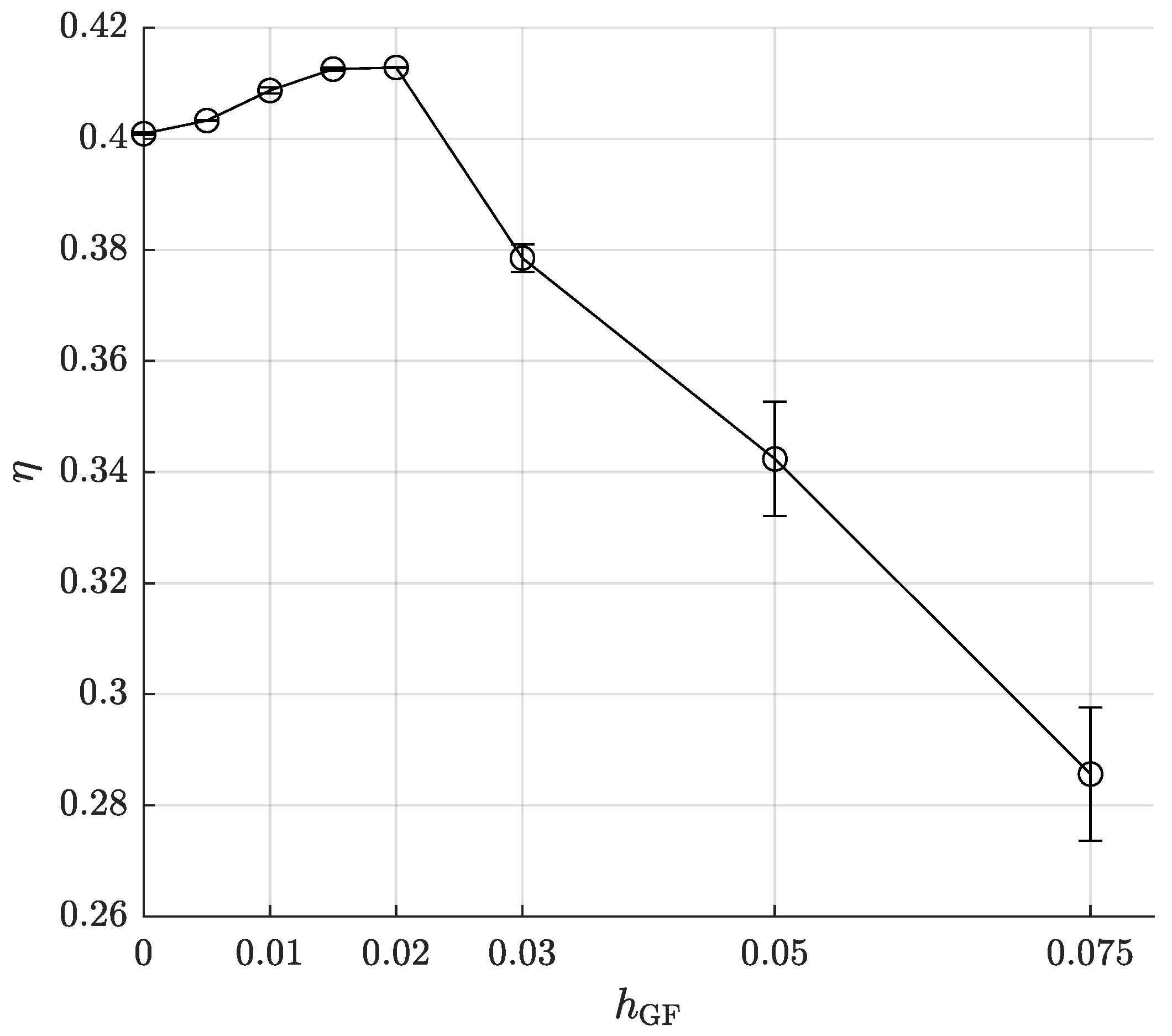
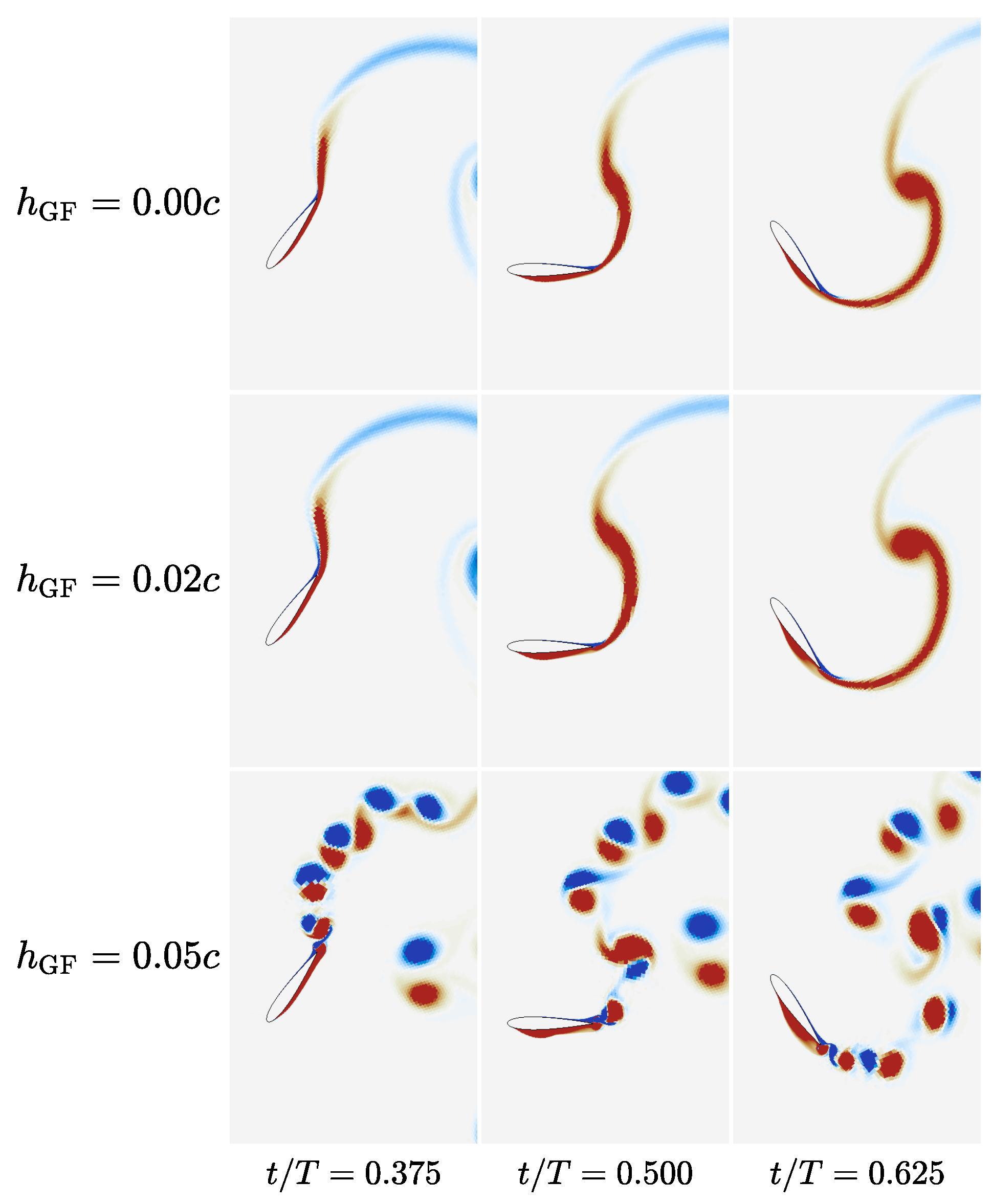
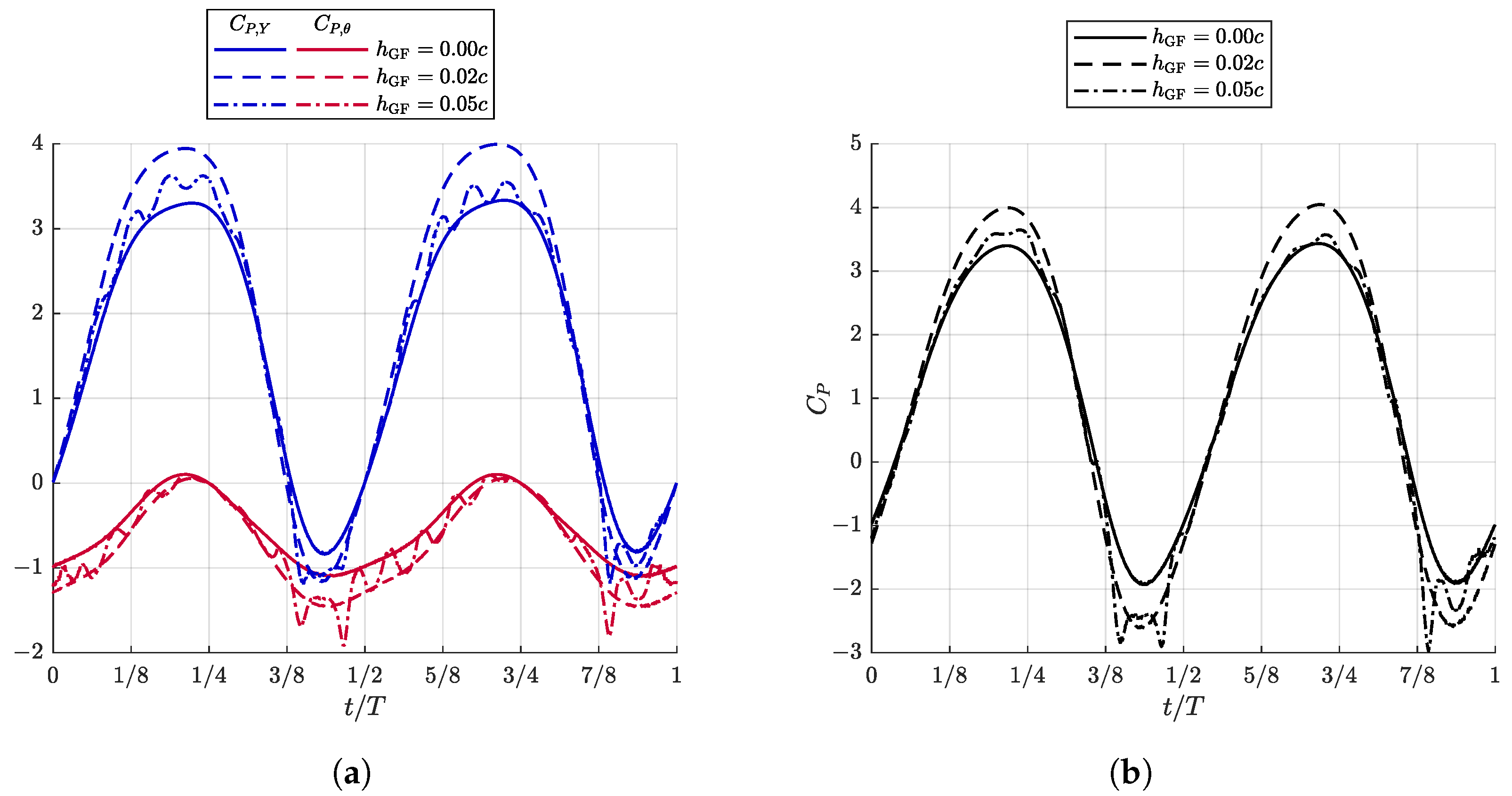
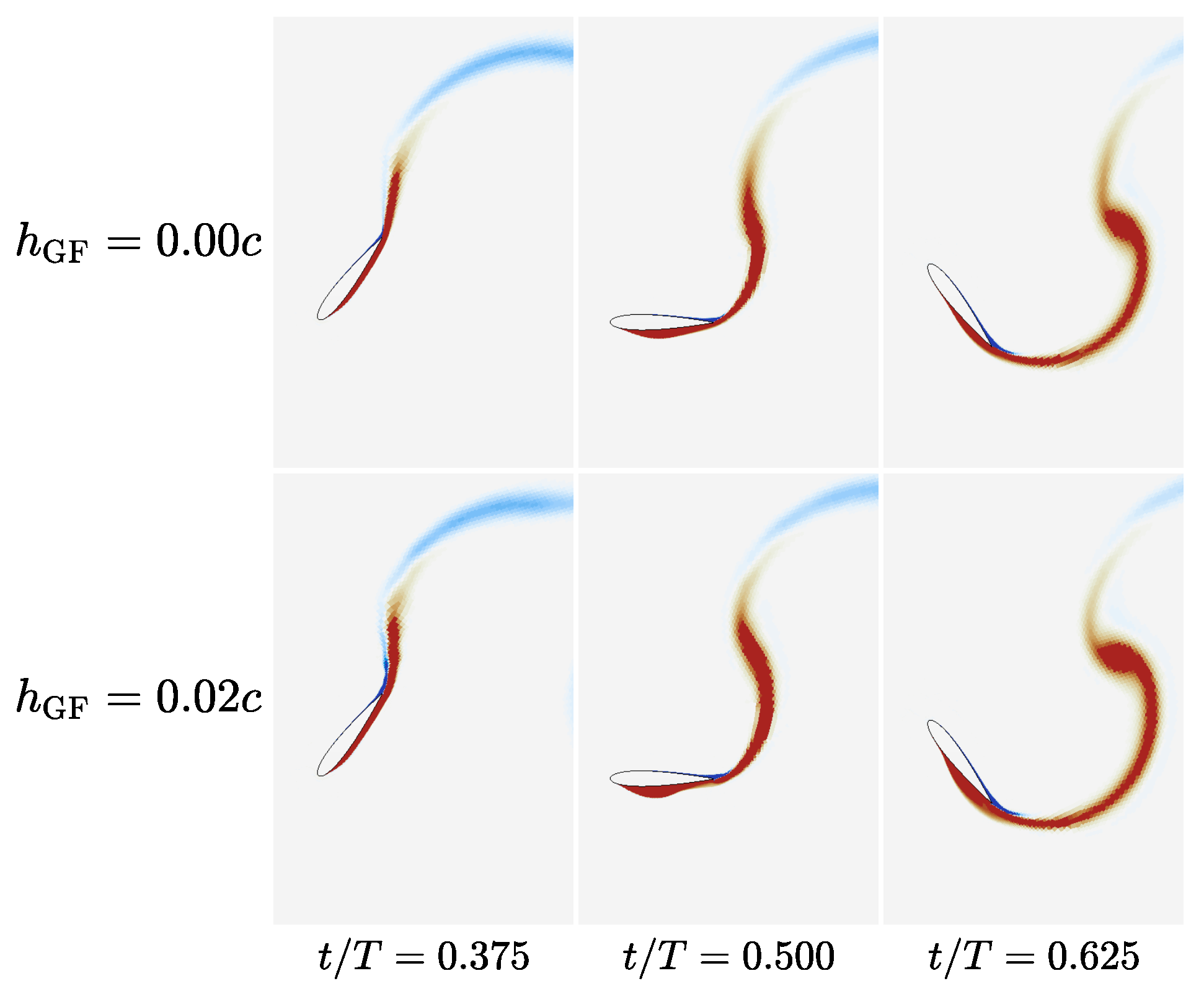
3.1. Impact of Double Gurney Flaps

The effect of the double GF on the OFT is first studied for a base case f = 0.18 yielding the best performance ( η = 0.401 ). Gurney flaps of heights ranging from h GF = 0.005 c to 0.075 c are added and the effect on performance η is presented in Figure 6.
Performance is improved by the addition of double GFs, for heights up to h GF = 0.02 c . Maximum performance of 0.413 is achieved for a relative improvement of + 3 % . Taller Gurney flaps have an adverse effect on performance, with h GF = 0.03 c decreasing performance below that of the base case and successively taller flaps having more adverse effects and yielding a more chaotic cycle-to-cycle variation, as shown by the error bars plotted.
Figure 7 shows the reversal portion of the oscillating cycle between t / T = 0.375 and 0.625 , that is, the moment in the cycle when the blade undergoes rapid pitching motion combined with a small to null heaving velocity, through which the heaving motion direction is reversed. This part of the cycle is where LEVS normally occur when the effective angle of attack is larger. We see that fitting a moderate double GF of h GF = 0.02 c has a qualitatively small effect on the vorticity field, whereas tall GFs of 0.05 c modify the flow field dramatically, introducing trailing-edge vortex shedding originating from the GFs and interacting with the OFT blade in a non-synchronized fashion, leading to the large cycle-to-cycle variations observed in Figure 6.
Going further and looking at the instantaneous power coefficients for the heaving motion and the pitching motion in Figure 8a, we observe that the double GF h GF = 0.02 c has increased the maximum instantaneous heaving power extraction around t / T = 0.625 to 0.75 . This is due to a larger vertical force (by means of increased lift) acting in the same direction as the heaving motion. The h GF = 0.05 c flaps have generated smaller maximum C P , Y increases, whilst adding heavy shedding that is not synchronized with the heaving cycle and thus generates important cycle-to-cycle variations. The negative contribution of the pitching motion is also observed through C P , θ . Both cases with flaps show increased power consumption during the reversal portion of the cycle. The combined contribution of both motions is shown in Figure 8b, and displays larger peaks for all cases equipped with flaps, both in power extraction ( C P > 0 ) and in power consumption ( C P < 0 ). This signal, once cycle-averaged ( C P ¯ ), was shown in Figure 6 to increase for h GF = 0.02 c but to decrease for h GF = 0.05 c . In short, h GF = 0.02 c provides a net positive balance between increased heaving force and increased power consumption during reversal, whilst h GF = 0.05 c increases the power consumption of the reversal cycle but provides limited increases in heaving force.

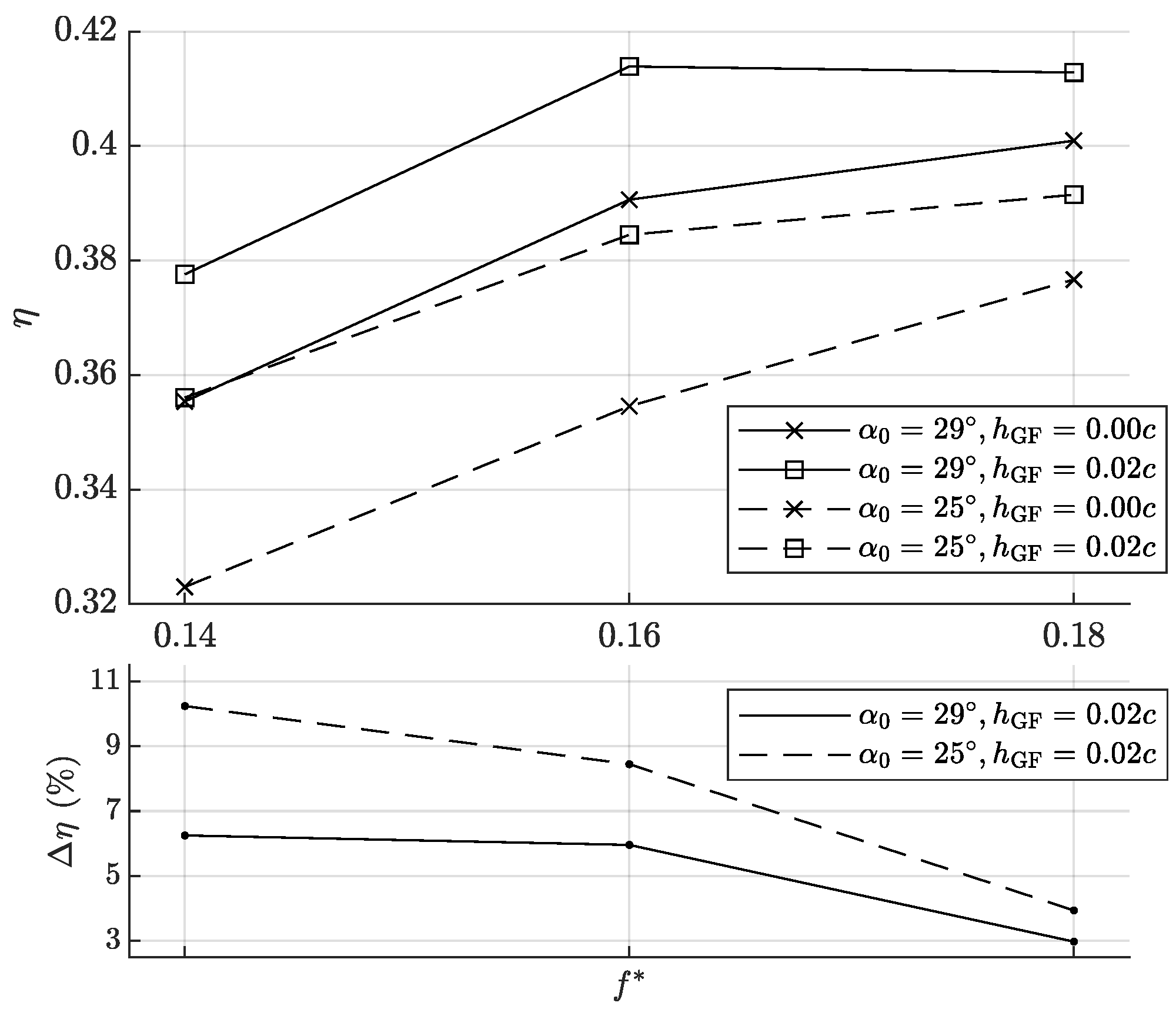
3.2. Operating Frequency

The effect of the double GF is now studied over five reduced operating frequencies ranging from f = 0.12 to 0.20 . Gurney flaps of various heights are fitted and the performance is plotted along with the base case (no flaps) in Figure 9. All f cases are improved by the addition of GFs, with maxima reached between h GF = 0.015 c and 0.02 c in all instances. For f = 0.12 , 0.14 and 0.20 , noteworthy performance improvements can be achieved up to h GF = 0.03 c , but for the other operating cases, performance decreases past h GF = 0.02 c . Furthermore, higher operating frequencies ( f = 0.16 to 0.20 ) display a sharp decrease in performance past h GF = 0.03 c , whereas lower reduced frequency cases have a more progressive decrease in performance.
We now concentrate on the effect of small GFs in relation to reduced operating frequency. The same f between 0.12 and 0.20 are selected, and flaps of h GF = 0.01 c and 0.02 c are considered. The performance and its relative gain are obtained in Figure 10.
We can see that, aside from our selected base case f = 0.18 , performance with the addition of double GFs can be improved by more than + 6.0 % when using a h GF = 0.02 c . The base case experiences a lower performance improvement of + 3.0 % . This can be analyzed by looking at Figure 11, which displays the vorticity field during reversal for the f = 0.16 case. Comparing the flow field with that of f = 0.18 in Figure 7, we observe that the latter has introduced a weaker vorticity region, fore of the GF located on the lower-side of the blade, which is not present on the case at f = 0.16 . This suggests that the f = 0.18 case is near a limit for fully attached cases, hence the lower performance improvements noted.

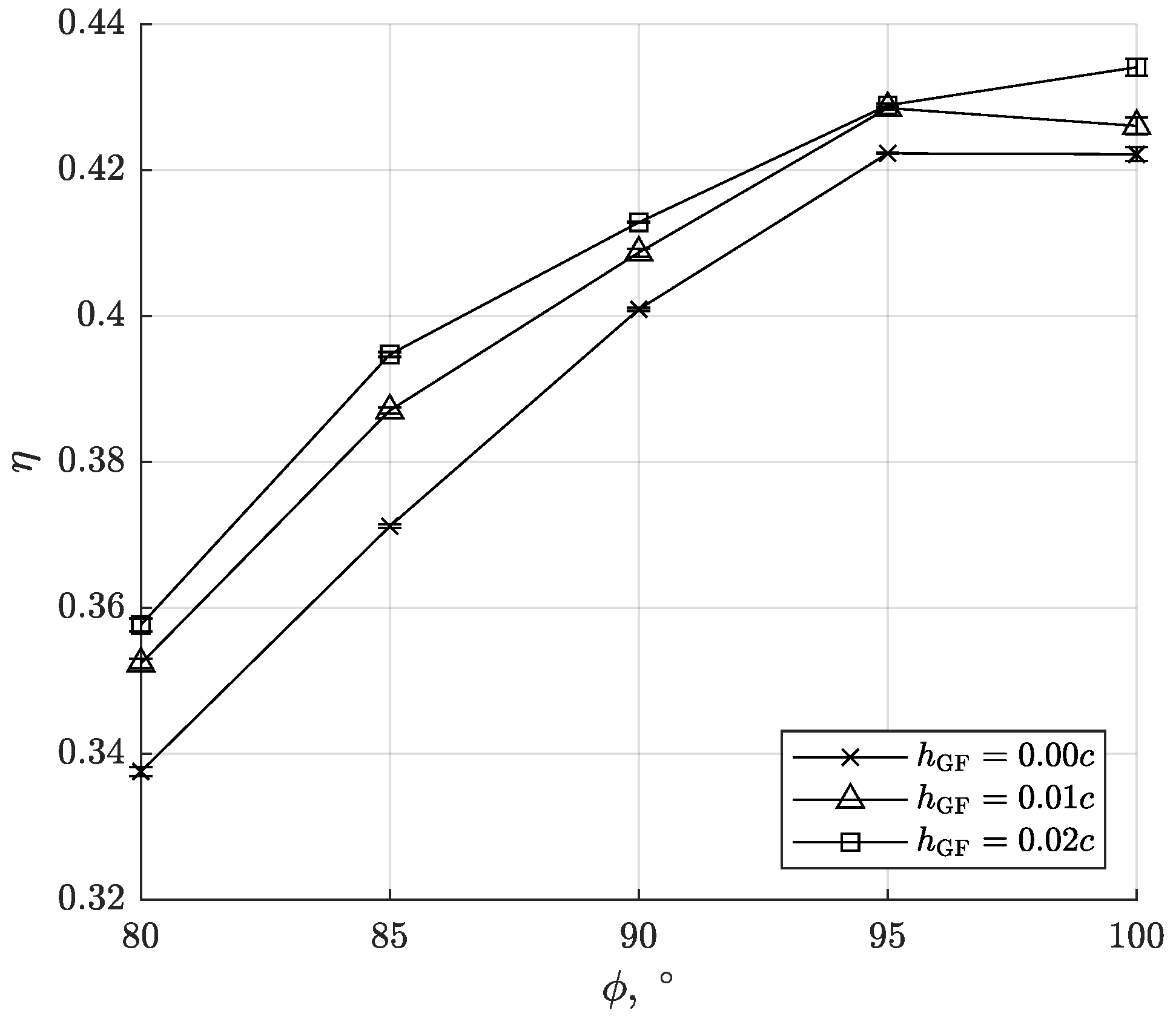
3.3. Pivot-Point Location
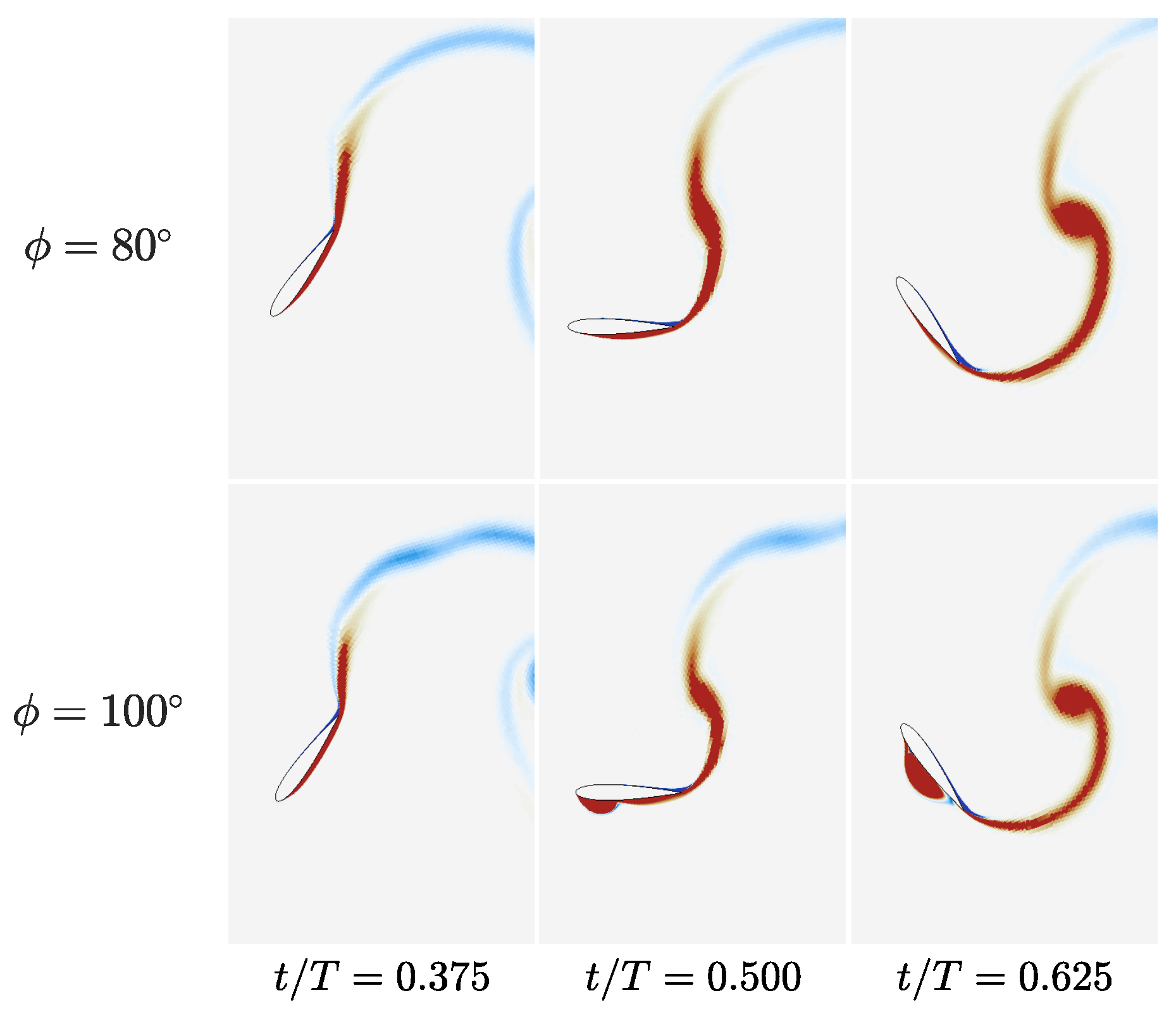
Pivot-point location was varied while keeping the kinematics quasi-similar and the maximum effective angle of attack constant, following the method described earlier in Section 2.1. The effect of pivot location x p is presented in Figure 12.
We see that moving the pivot-point whilst keeping α 0 constant has a definite impact on performance. An optimum for the base case (no GF) can be found around x p = 0.4 c with η = 0.403 . Fitting double GFs can improve the performance of all cases, with a relative impact similar at most pivot-point locations. Maximum performance of η = 0.419 is reached for x p = 0.4 c when a double GF of h GF = 0.02 c is fitted (relative improvement of + 3.9 % over no-flap case at x p = 0.4 c and of + 4.5 % over the base case at x p = c / 3 ).
Varying pivot-point location without reproducing quasi-similar motions through the method described earlier imparts kinematics changes which impact vortex generation during the reversal motion of the foil. For instance, to keep α 0 constant, the pitching amplitude must be adjusted as well as heaving amplitude, which impact the maximum angular acceleration of the blade.

3.4. Motion Phase

The effect of motion phase on turbine performance and double GF effectiveness is presented in Figure 13. Double Gurney flaps are fitted to OFTs operating at a fixed f = 0.18 , and the phase between pitch and heave motions is varied from ϕ = 80 to 100 , whilst keeping α 0 = 29 and H 0 = c . The effect on η is noticeable on both the base case ( ϕ = 90 ) and on cases with double GFs fitted, and is of greater magnitude than simply fitting GFs.
Observing the impact of motion phase on the flow field in Figure 14 shows that the motion phase dramatically impacts the reversal portion of the oscillation cycle. A large leading-edge vortex is now apparent at ϕ = 100 , although it is not strictly shed, whereas ϕ = 80 shows thinner vorticity region on the lower-side compared with the base case at ϕ = 90 presented in Figure 7. This indicates that the criterion selected to avoid LEVS of α 0 = 29 is not strictly sufficient if ϕ 90 .

3.5. Maximum Effective Angle of Attack

A maximum effective angle of attack of 29 was selected as a starting point in the current study in order to have efficient cases without LEVS. The performance of OFTs operating between f = 0.12 and 0.20 was presented earlier in Figure 10, and the relative performance improvements when fitted with double Gurney flaps was shown to remain below + 7 % .
Performance and its relative improvement is now compared in Figure 15 for f = 0.14 to 0.18 between OFTs operating at α 0 = 29 and at α 0 = 25 , before and after fitting double GFs of h GF = 0.02 c .
Performance is still improved in all turbines, with relative improvements ranging from ≈ + 3 % to more than + 10 % . The fact that the same GFs ( h GF = 0.02 c ) on different turbines produce different results is now evidenced. The highest relative performance improvement ( + 10.2 % ) is obtained for the lowest-performing no-flap case ( f = 0.14 and α 0 = 25 ). Further, turbines operating at α 0 = 25 all produce a lower base performance, but see greater improvements by the addition of double GFs, compared with α 0 = 29 . Relative improvements are greater for lower reduced-frequency cases ( f = 0.14 ), which also display the smallest performance in the first place.
Nevertheless, maximum performance is still obtained with the higher α 0 case and the highest reduced frequency, as found in Section 3.2. This highlights the importance of selecting already high-performance turbine cases when testing geometric improvements, and the misleading message of reporting large relative improvements based on tests conducted on initially poor-performance turbines.

3.6. Discussion

The optimal double Gurney flap height for the base turbine case studied is located between h GF = 0.015 c and 0.02 c . For stationary airfoils, the optimal double GF that improved performance—i.e., L / D ratio—was found by Genest and Dumas [35] to be h GF = 0.005 c at R e = 5 × 10 5 on a NACA 0015 foil, but the lift coefficient was found to be increased by GFs up to h GF = 0.02 c . OFTs can therefore benefit from much taller flaps, compared to foils at fixed angles of attack. This is in part due to the fact that the OFT’s performance is derived from power-extraction, which is directly related to lift and moment on the blade, but to a lesser degree to drag.
In fact, the best double GFs used here ( h GF = 0.015 c and 0.02 c ) were found by Genest and Dumas [35] to have an increased coefficient of drag, a greater lift slope. and a more negative and negatively sloped moment coefficient compared with a clean airfoil. This led to a reduced airfoil performance ( L / D ) when compared with smaller flaps or no-flap airfoils. When applied to turbines, it is expected that heaving power extraction would be increased by lift, and that pitching power extraction would be diminished. This is indeed what we observed in Figure 8a.
From those observations, we can infer that the main beneficial characteristic of an airfoil fitted with a double GF and used as an OFT blade is to have a greater lift slope. The more negative pitching moment associated with the double GF, a device fitted at the trailing-edge that shifts the pressure distribution aftwards [35], is detrimental to power-extraction. This negative effect could have been reduced by changing pivot-point location or motion phase, yet similar performance improvements were found when tested in Section 3.3 and Section 3.4.
Finally, we should note that the conclusions derived from this study of the double GF may only be applicable to a single turbine, and not necessarily to turbine arrays, where the increased turbine drag will impact wake-recovery and could be detrimental to the array’s power extraction.

4. Conclusions

The numerical investigation of double Gurney flaps applied to OFT turbines operating with a maximum effective angle of attack of α 0 = 29 without the presence of LEVS has demonstrated the interest of the double GF to improve the power-extraction performance of turbines already operating with high extraction performance. Performance improvements from + 3.0 % to + 10.2 % were found over all cases observed.
The conclusions of this paper can be summarized as follows:
  • Overall, the effect of adding double GFs remains modest, but has been shown to always be beneficial if its height is kept within the prescribed limits found (max h GF = 0.02 c ). This limit suggests that the optimal double GFs for OFT performance are the ones yielding the highest lift coefficient on static airfoils, regardless of airfoil performance ( L / D ).
  • Selecting a maximum effective angle of attack α 0 is not a sufficient criterion to avoid LEVS. Indeed, changing motion phase has shown that leading edge vortices can start to appear, yet remain attached and are not being shed.
  • Changing pivot-point location also has an important effect on performance, yet the impact of double GFs still remains qualitatively the same.
  • Adding double GFs is a passive modification, applicable even to the highest-performing OFTs, that offers a good potential for making the OFT an even more attractive concept in the development of hydrokinetic turbines.
Future works could take advantage of the increased lift slope of the double GF by using a proportionally longer power extraction period. For instance, this could be performed by imposing large heaving amplitudes and a modified pitching function that locates the reversal motion only at the limits of heaving, such as that explored by Picard-Deland et al. [12] for cases of very large heaving amplitudes.
Additionally, the effect of Reynolds number on the optimal Gurney flap height should now be studied, stemming from the conclusions of Giguère et al. [34] and Genest and Dumas [35] regarding the scaling relative to the boundary layer thickness. A boundary layer thickness scaling in the context of OFTs would be difficult to quantify, and as shown by the taller GFs employed, might not be fully applicable. Hence, the effect of Reynolds number on the GFs’ performance improvements would provide more insight into their proper scaling.
Finally, studying the effect of perturbed flow conditions at the inlet could provide insight into the effect of double GFs on the boundary layer robustness and characteristics.

Author Contributions

Conceptualization, B.G. and G.D.; Methodology, B.G.; Validation, B.G.; Formal analysis, B.G. and G.D.; Investigation, B.G.; Resources, G.D.; Data curation, B.G.; Writing—original draft, B.G.; Writing—review & editing, G.D.; Visualization, B.G.; Supervision, G.D.; Funding acquisition, G.D. All authors have read and agreed to the published version of the manuscript.

Funding

This research was made possible through access to the high performance computing resources provided by Calcul Québec (calculquebec.ca) and the Digital Research Alliance of Canada (alliancecan.ca) (RAPI qcy-255), and was funded by the Natural Sciences and Engineering Research Council of Canada (NSERC Discovery Grant RGPIN-2018-04527 and NSERC CGS M scholarship).

Data Availability Statement

Not applicable.

Acknowledgments

The authors would like to acknowledge all members of the CFD Laboratory LMFN, and in particular Kevin Gunther, for their everlasting support and many insightful discussions. We also wish to thank Thomas Kinsey for graciously providing the original data used in Ref. [18].

Conflicts of Interest

The authors declare no conflict of interest, and the funders had no role in the design of the study; in the collection, analyses, or interpretation of data; in the writing of the manuscript; or in the decision to publish the results.

Abbreviations

The following abbreviations are used in this manuscript:
GFGurney flap
LEVSLeading-edge vortex shedding
OFTOscillating-foil turbine
TStime-step
URANSUnsteady Reynolds-averaged Navier–Stokes

References

  1. Lemonis, G.; Cutler, J. Wave and Tidal Energy Conversion. In Encyclopedia of Energy; Elsevier: Amsterdam, The Netherlands, 2004; pp. 385–396. [Google Scholar] [CrossRef]
  2. McKinney, W.; DeLaurier, J. The Wingmill: An Oscillating-Wing Windmill. J. Energy 1981, 5, 109–115. [Google Scholar] [CrossRef]
  3. Kinsey, T.; Dumas, G.; Lalande, G.; Ruel, J.; Méhut, A.; Viarouge, P.; Lemay, J.; Jean, Y. Prototype testing of a hydrokinetic turbine based on oscillating hydrofoils. Renew. Energy 2011, 36, 1710–1718. [Google Scholar] [CrossRef]
  4. Jiang, W.; Zhang, D.; Xie, Y. Numerical investigation into the effects of arm motion and camber on a self-induced oscillating hydrofoil. Energy 2016, 115, 1010–1021. [Google Scholar] [CrossRef]
  5. Sitorus, P.E.; Ko, J.H. Power extraction performance of three types of flapping hydrofoils at a Reynolds number of 1.7E6. Renew. Energy 2019, 132, 106–118. [Google Scholar] [CrossRef]
  6. Peng, Z.; Zhu, Q. Energy harvesting through flow-induced oscillations of a foil. Phys. Fluids 2009, 21, 123602. [Google Scholar] [CrossRef] [Green Version]
  7. Veilleux, J.C.; Dumas, G. Numerical optimization of a fully-passive flapping-airfoil turbine. J. Fluids Struct. 2017, 70, 102–130. [Google Scholar] [CrossRef]
  8. Boudreau, M.; Dumas, G.; Rahimpour, M.; Oshkai, P. Experimental investigation of the energy extraction by a fully-passive flapping-foil hydrokinetic turbine prototype. J. Fluids Struct. 2018, 82, 446–472. [Google Scholar] [CrossRef]
  9. Shimizu, E.; Isogai, K.; Obayashi, S. Multiobjective Design Study of a Flapping Wing Power Generator. J. Fluids Eng. 2008, 130, 021104. [Google Scholar] [CrossRef]
  10. Zhu, Q.; Peng, Z. Mode coupling and flow energy harvesting by a flapping foil. Phys. Fluids 2009, 21, 033601. [Google Scholar] [CrossRef] [Green Version]
  11. Boudreau, M.; Gunther, K.; Dumas, G. Investigation of the energy-extraction regime of a novel semi-passive flapping-foil turbine concept with a prescribed heave motion and a passive pitch motion. J. Fluids Struct. 2019, 84, 368–390. [Google Scholar] [CrossRef]
  12. Picard-Deland, M.; Olivier, M.; Dumas, G.; Kinsey, T. Oscillating-Foil Turbine Operating at Large Heaving Amplitudes. AIAA J. 2019, 57, 5104–5113. [Google Scholar] [CrossRef]
  13. Dumas, G.; Kinsey, T. Eulerian simulations of oscillating airfoils in power extraction regime. Adv. Fluid Mech. VI 2006, 52, 10. [Google Scholar]
  14. Kinsey, T.; Dumas, G. Parametric Study of an Oscillating Airfoil in a Power-Extraction Regime. AIAA J. 2008, 46, 1318–1330. [Google Scholar] [CrossRef]
  15. Kinsey, T.; Dumas, G. Optimal operating parameters for an oscillating foil turbine at Reynolds number 500,000. AIAA J. 2014, 52, 1885–1895. [Google Scholar] [CrossRef]
  16. Kinsey, T.; Dumas, G. Three-Dimensional Effects on an Oscillating-Foil Hydrokinetic Turbine. J. Fluids Eng. 2012, 134, 071105. [Google Scholar] [CrossRef]
  17. Kinsey, T.; Dumas, G. Optimal Tandem Configuration for Oscillating-Foils Hydrokinetic Turbine. J. Fluids Eng. 2012, 134, 031103. [Google Scholar] [CrossRef]
  18. Kinsey, T.; Dumas, G. Computational Fluid Dynamics Analysis of a Hydrokinetic Turbine Based on Oscillating Hydrofoils. J. Fluids Eng. 2012, 134, 021104. [Google Scholar] [CrossRef]
  19. Young, J.; Ashraf, M.A.; Lai, J.C.S.; Platzer, M.F. Numerical Simulation of Fully Passive Flapping Foil Power Generation. AIAA J. 2013, 51, 2727–2739. [Google Scholar] [CrossRef]
  20. Drofelnik, J.; Campobasso, M.S. Comparative turbulent three-dimensional Navier–Stokes hydrodynamic analysis and performance assessment of oscillating wings for renewable energy applications. Int. J. Mar. Energy 2016, 16, 100–115. [Google Scholar] [CrossRef] [Green Version]
  21. Jeanmonod, G.; Olivier, M. Effects of chordwise flexibility on 2D flapping foils used as an energy extraction device. J. Fluids Struct. 2017, 70, 327–345. [Google Scholar] [CrossRef] [Green Version]
  22. Liu, W.; Xiao, Q.; Zhu, Q. Passive Flexibility Effect on Oscillating Foil Energy Harvester. AIAA J. 2016, 54, 1172–1187. [Google Scholar] [CrossRef] [Green Version]
  23. Dang, H.N.L.; Jeong, D.; Ko, J.H. Study of the power performance of a variable-camber hydrofoil used in a flapping tidal stream turbine. J. Mar. Sci. Technol. 2022, 27, 1148–1162. [Google Scholar] [CrossRef]
  24. Liu, G.; Tian, C.; Wu, L.; Liu, X. Energy extraction of oscillating foil with an active deflecting trailing-edge flap. J. Renew. Sustain. Energy 2021, 13, 064501. [Google Scholar] [CrossRef]
  25. Sun, G.; Wang, Y.; Xie, Y.; Ma, P.; Zhang, Y. Hydrodynamic and energy extraction properties of oscillating hydrofoils with a trailing edge flap. Appl. Ocean Res. 2021, 110, 102530. [Google Scholar] [CrossRef]
  26. Xie, Y.; Jiang, W.; Lu, K.; Zhang, D. Numerical investigation into energy extraction of flapping airfoil with Gurney flaps. Energy 2016, 109, 694–702. [Google Scholar] [CrossRef]
  27. Zhu, B.; Huang, Y.; Zhang, Y. Energy harvesting properties of a flapping wing with an adaptive Gurney flap. Energy 2018, 152, 119–128. [Google Scholar] [CrossRef]
  28. Sun, G.; Wang, Y.; Xie, Y.; Lv, K.; Sheng, R. Research on the effect of a movable gurney flap on energy extraction of oscillating hydrofoil. Energy 2021, 225, 120206. [Google Scholar] [CrossRef]
  29. Wu, X.; Zhang, X.; Tian, X.; Li, X.; Lu, W. A review on fluid dynamics of flapping foils. Ocean Eng. 2020, 195, 106712. [Google Scholar] [CrossRef]
  30. The Engineering Business Limited. Stingray Tidal Energy Device—Phase 3; Tech. Rep.; Crown Copyright; The Engineering Business Limited: Stocksfield, UK, 2005. [Google Scholar]
  31. Anderson, J.M.; Streitlien, K.; Barrett, D.S.; Triantafyllou, M.S. Oscillating foils of high propulsive efficiency. J. Fluid Mech. 1998, 360, 41–72. [Google Scholar] [CrossRef] [Green Version]
  32. Jones, K.; Platzer, M. Numerical computation of flapping-wing propulsion and power extraction. In Proceedings of the 35th Aerospace Sciences Meeting and Exhibit, Reno, NV, USA, 6–9 January 1997. [Google Scholar] [CrossRef]
  33. Davids, S.T. A Computational and Experimental Investigation of a Flutter Generator. Master’s Thesis, Naval Postgraduate School, Monterey, CA, USA, 1999. [Google Scholar]
  34. Giguère, P.; Dumas, G.; Lemay, J. Gurney Flap Scaling for Optimum Lift-to-Drag Ratio. AIAA J. 1997, 35, 1888–1890. [Google Scholar] [CrossRef]
  35. Genest, B.; Dumas, G. Numerical Investigation into Single and Double Gurney Flaps for Improving Airfoils Performance. J. Aircr. 2023; in press. [Google Scholar]
  36. Betz, A. Das Maximum der theoretisch möglichen Ausnützung des Windes durch Windmotoren. Z. Gesamte Turbinenwesen 1920, 26, 307–309. [Google Scholar]
Figure 1. Double Gurney flap geometry and definition.
Energies 16 02885 g001
Figure 2. Heaving motion function h ( t ) of two locations along the chord ( x / c ) for a pivot location x p = c / 3 , showing how the new heaving amplitude and motion phase are determined.
Energies 16 02885 g002
Figure 3. Representation of the kinematic parameters of the OFT equipped with a double GF (adapted with permission from Kinsey and Dumas [15]).
Energies 16 02885 g003
Figure 4. Mesh and domain specifications, including boundary conditions.
Energies 16 02885 g004
Figure 5. Comparison of instantaneous C P and C Y for 3 mesh resolutions and with Kinsey and Dumas [18] reference, for case f = 0.16 , θ 0 = 75 , H 0 = c , ϕ = 90 , x p = c / 3 (without GF).
Energies 16 02885 g005
Figure 6. Effect of Gurney flaps on the performance of an OFT operating at f = 0.18 , H 0 = c , α 0 = 29 , ϕ = 90 fitted with various heights of double Gurney flaps (error bars showing variation of η over last 5 cycles).
Energies 16 02885 g006
Figure 7. Normalized z-vorticity field during reversal for three double GF heights at f = 0.18 . Positive vorticity in red, negative vorticity in blue.
Energies 16 02885 g007
Figure 8. Instantaneous signals for three GF cases at f = 0.18 and α 0 = 29 . (a) Power coefficients of heave and pitch. (b) Total power extraction coefficient.
Energies 16 02885 g008
Figure 9. Effect of Gurney flaps on the performance of OFTs operating at reduced frequencies from f = 0.12 to 0.20 , fitted with double GFs of h GF = 0.005 c to 0.075 c .
Energies 16 02885 g009
Figure 10. Effect on performance (top) and relative performance improvement (bottom) of OFTs operating at different reduced frequencies ( f ) with α 0 = 29 when fitted with double GFs of h GF = 0.01 c and 0.02 c .
Energies 16 02885 g010
Figure 11. Normalized z-vorticity field during reversal for two double GF heights at f = 0.16 . Positive vorticity in red, negative vorticity in blue.
Energies 16 02885 g011
Figure 12. Effect on performance of fitting double GFs on OFTs with different pivot-point locations ( x p ) at f = 0.18 and α 0 = 29 .
Energies 16 02885 g012
Figure 13. Effect on performance of fitting double GFs on OFTs with different motion phases at f = 0.18 and α 0 = 29 .
Energies 16 02885 g013
Figure 14. Normalized z-vorticity field during reversal for two motion phases at f = 0.18 . Positive vorticity in red, negative vorticity in blue.
Energies 16 02885 g014
Figure 15. Effect on performance (top) and on relative performance improvement (bottom) of a h GF = 0.02 c double GF fitted to turbines operating at α 0 = 29 and α 0 = 25 .
Energies 16 02885 g015
Table 1. Results for numerical parameters sensitivity studies and comparison with Kinsey and Dumas [18]. (Bold indicates the case with numerical parameters retained for the study).
CaseTime Steps/
Cycle
Cells
(Near-Foil)
C ^ Y C ^ M C P ¯
Reference [18]20003.168 (+2.64%)0.613 (−0.75%)1.023 (+2.02%)
Coarse mesh200035,0003.016 (−2.28%)0.618 (+0.06%)0.988 (−1.51%)
Standard (Medium mesh)200066,6003.0870.6181.003
Fine mesh2000145,0003.099 (+0.41%)0.618 (+0.04%)1.006 (+0.30%)
Coarse TS/cycle100066,6003.126 (+1.29%)0.616 (−0.20%)1.002 (−0.07%)
Fine TS/cycle400066,6003.069 (−0.58%)0.619 (+0.18%)1.003 (−0.01%)
Disclaimer/Publisher’s Note: The statements, opinions and data contained in all publications are solely those of the individual author(s) and contributor(s) and not of MDPI and/or the editor(s). MDPI and/or the editor(s) disclaim responsibility for any injury to people or property resulting from any ideas, methods, instructions or products referred to in the content.

