1. Introduction
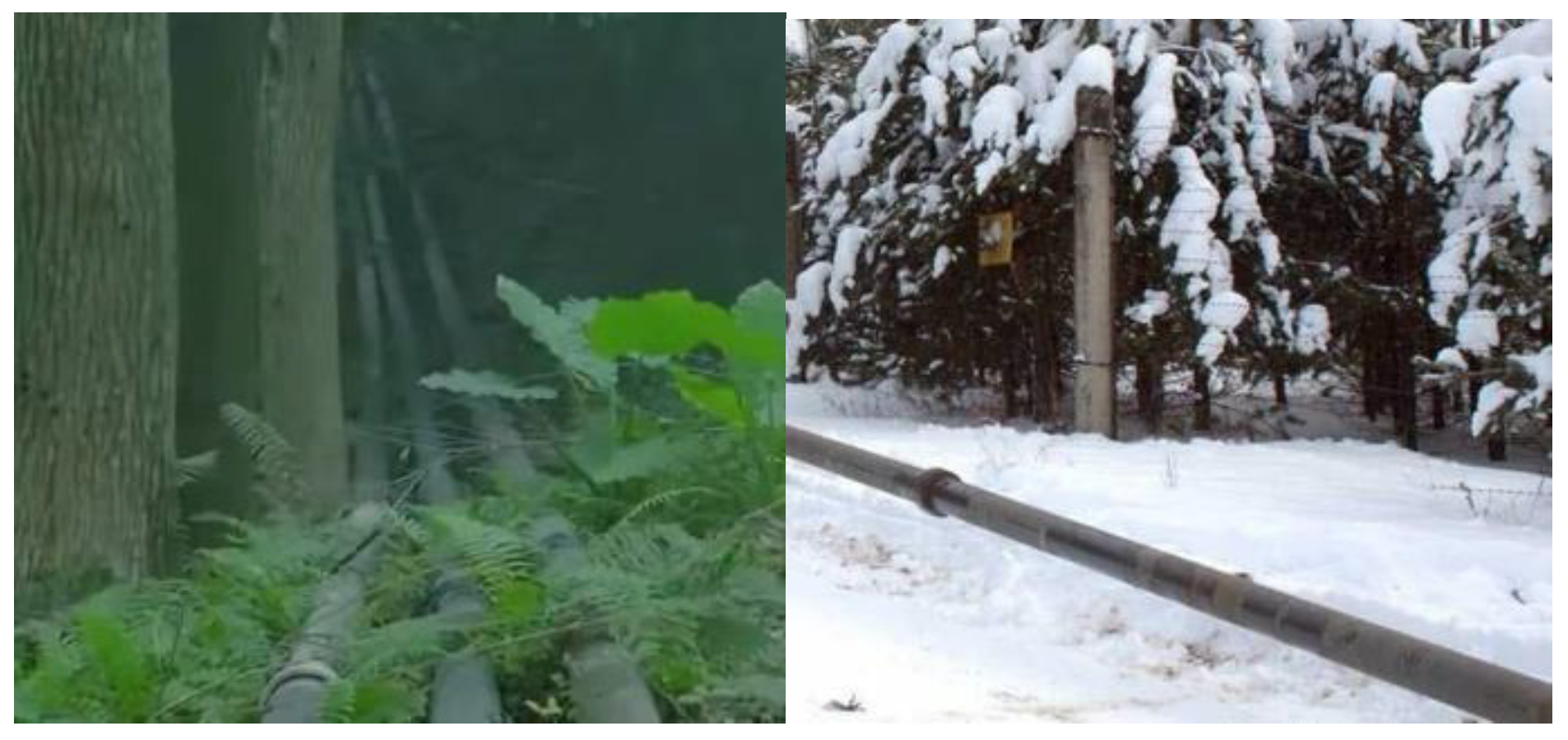
A mobile pipeline is an assembly-type system composed of pipes, mobile oil pumps, valves, metering instruments, etc., which can be connected by detachable joints (socket type or slotted head type). It has the characteristics of rapid laying, withdrawal and flexible maneuvering [
1]. Therefore, a mobile pipeline is often used to transport oil in hard-to-reach areas, as shown in
Figure 1.
Different to the product pipeline, the mobile pipeline must be emptied of oil and recover it to the oil tank or the oil carrier when the mobile pipeline completes the oil transmission task and pipeline maintenance. At present, there are three kinds of emptying methods for mobile pipelines: artesian, gas displacement and water displacement. Artesian is accomplished by the height difference and gravity of the oil itself. It can only be implemented in the low-lying section of the pipeline, which requires high terrain. Gas displacing oil uses an air compressor to inject the compressed air into the upstream of the pipeline, displacing the oil in the pipeline from the downstream. Because the pressure provided by the equipped motorized air compressor is far lower than the working pressure of the oil pump, the emptying-out operation needs to be carried out in sections, which makes the process complicated and slow. At the same time, a large amount of oil and gas mixture will be produced in the process, which is not safe or convenient. Water displacing oil uses the oil pump of the pipeline system to directly inject water into the pipeline and gradually push the oil in the pipeline out of the pipeline. In this process, a mixture of oil and water will be formed, which will lead to certain economic losses and the decline of oil quality. Compared with artesian and gas displacing oil, water displacing oil has the advantages of fewer requirements on terrain, direct use of oil transport equipment, a simple process, fast speed, small oil and gas loss and high safety, so it is widely used. Therefore, if the temperature and water source conditions permit, emptying by water displacing oil is preferred [
2].
At present, the determination of emptying process parameters and the tracking, measurement and cutting of the oil–water mixture of mobile pipelines are mainly based on the oil–oil alternating transport theory of product oil pipelines [
3]; due to the insolubility of the oil phase and water phase, the oil–water mixing mechanism and flow characteristics of the water displacing oil are different from the oil–oil alternating transport of product oil. Secondly, there are density and polarity differences between the oil phase and the water phase, especially under conditions of increased pressure and mixing in the pipeline, which makes it impossible to form a stable emulsion. Under the action of buoyancy, the oil phase gathers at the high point of the pipeline and forms a liquid accumulation, which is difficult to carry and discharge by water flow. As a result, the emptying efficiency of the mobile pipeline is low. At the same time, it is found that the oil–water mixing section is several kilometers long during the emptying process, which not only consumes a lot of water resources, but also wastes a lot of time and reduces the emptying efficiency. The small diameter of the pipeline, the large number of joints and the fluctuation of the terrain make the oil in a mobile pipeline easy to accumulate and not easy to carry. There is a large difference in the control of an oil–water mixture in a product oil pipeline and mobile pipeline. Those problems increase the difficulty of emptying.
At present, there are few summaries on the oil–water flow characteristics of water-top emptying in mobile pipelines. Research progress on the oil–water two-phase flow characteristics of the displacement flow of oil by water in mobile pipelines is mainly summarized as flow pattern change in the process of mobile pipeline emptying [
3]. This literature compares two main flow classification methods for a two-phase flow pattern. The conclusion of this review is that with the increase of flow velocity in the pipeline, there will be stratified flow, annular flow, discrete flow and other flow patterns, but the conclusion is still based on the sequential transmission theory of product pipelines.
This paper aims to review the current research status of oil–water flow characteristics from macro and micro perspectives, by comparing the difference between the sequence transportation of product oil pipelines and emptying by water displacing oil of mobile pipelines and analyze the shortcomings of the current research results applied to mobile pipelines. The research direction proposed is for the emptying by water displacing oil of a mobile pipeline itself. Instead of referring to the theory of product pipeline sequential transportation, it will provide references and ideas for further promoting the study of oil–water flow characteristics of emptying by water displacing oil in mobile pipelines.
2. Method
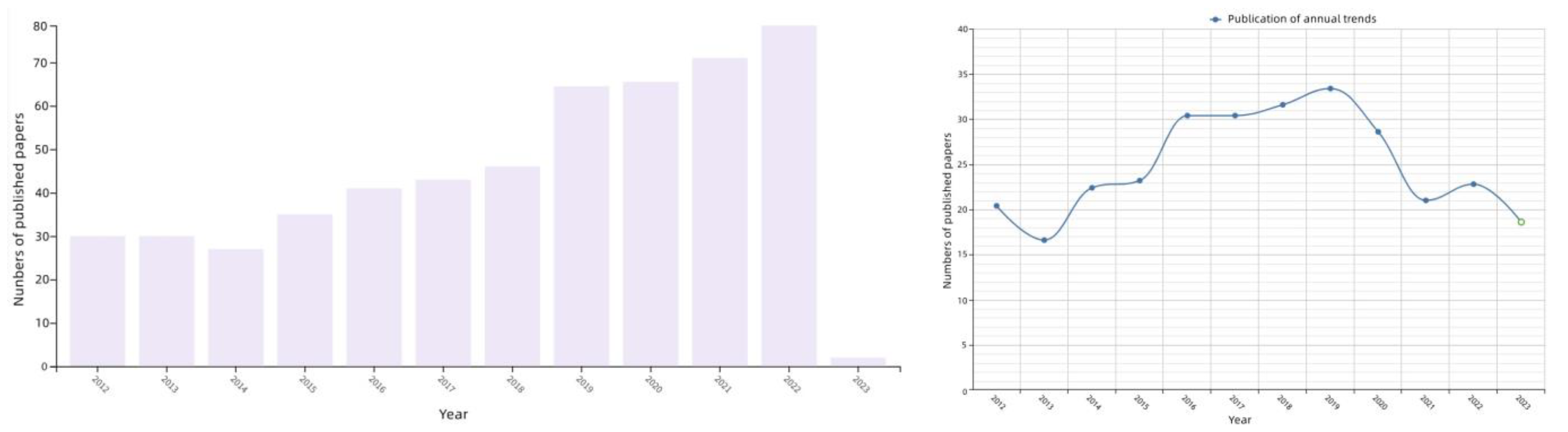
In order to systematically review the research status of oil–water flow characteristics in emptying by water displacing oil in mobile pipelines and explore the differences between mobile pipelines and oil–water flow characteristics in the sequential transmission of product oil pipelines, we conducted a systematic literature search under the guidance of science librarians. Literature retrieval sources mainly included “Web of Science Core Collection” and “CNKI” retrieval databases. The search was conducted on 1 February 2023. The search was carried out in two directions. First, according to the keyword “oil-water flow characteristics”, a large number of research literatures from 2012 to now were obtained, as shown in
Figure 2. Then, based on the search results, according to the macro and micro research perspectives, the selection included the macro-level including “flow pattern, pressure drop, water content” and the micro-level including “local flow field, droplet dispersion pattern”; they are classified according to the research direction of the full paper. Second, based on the keywords “oil-water flow characteristics”, we searched the keywords “measuring equipment”. In order to ensure a comprehensive review of the historical evolution of the measurement method, a large number of documents from 2001 to now were retrieved, and duplicate items and other documents unrelated to this paper were excluded. The specific categories are shown in
Table 1.
After the search, all the references were screened by title and abstract by two researchers. All the references meeting the prerequisite criteria but with uncertain research contents were screened, and the literatures with repeated research contents were excluded. If two researchers had a disagreement, a third researcher was sought to resolve it. They carefully reviewed the list of references included in the study and related reviews to ensure that their content and format were accurate.
In the third and fourth part of this paper, 73 papers (
Table 1) related to oil–water flow characteristics are collected and systematically reviewed. The fifth part deeply analyzes the deficiencies in the formation mechanism of the oil–water mixture, displacing flow characteristics of immiscible fluids and flow characteristics of water carrying oil. It is found that the liquid–liquid interface is usually assumed as the solid–liquid interface with sliding velocity in current studies. The dynamic evolution of liquid–liquid interface with time under the action of flow field and the study of droplet separation, deformation and mixing characteristics at the interface are lacking. The paper then puts forward five development directions which can be studied in the next step to provide reference and thought for further research on oil–water flow characteristics of emptying by water displacing oil in mobile pipelines. The sixth part makes a comprehensive summary of the whole article.
3. Measuring Equipment
In the 1960s and 1970s, due to the limitation of measurement technology, scholars mainly relied on the naked eye to distinguish different oil flow patterns, and there were limitations in the cognition of oil–water flow law [
59]. With the development of technology, a large amount of measuring equipment based on electricity and optics has been gradually used in the study of the law of oil–water flow, including a resistance probe, a focused beam reflection measurement (FBRM) instrument, laser velocimetry equipment and a gamma phase division instrument, etc.
Resistance probes are mainly used for two-phase flow pattern detection, pipeline cross section average and local phase fraction measurement [
60], interface wave capture and continuous phase fluid identification of dispersed flow, which are mainly reflected in the height of the oil–water interface under stratified smooth flow, stratified wave flow and two-fluid flow patterns. There is also the measurement of shape [
61,
62,
63] and interfacial instability [
59,
64] as well as the estimation of the average phase separation rate of dispersed systems.
FBRM is mainly used to measure droplet distribution in dispersed flow. Relevant studies mainly focus on exploring the relationship between microscopic droplet distribution and the stability of the emulsion system, and studying the influence of different tube flow conditions on droplet distribution and the influence of effective viscosity and pressure drop change law in the dispersed system [
65,
66].
The optical equipment mainly includes a high-speed camera, planar laser induction fluorescence (PLIF), a laser doppler velocimeter (LDV) and a particle image velocimeter (PIV). At present, it is mainly used for the identification of stratified flow, two-fluid flow and dispersed flow in the oil–water pipe flow experiment, as well as the capture of microscopic morphology and flow field changes in the flow pattern transformation process [
27,
28,
67,
68,
69,
70,
71,
72].
A gamma phase divider is used to distinguish flow patterns and measure the average phase divider at fixed positions [
67,
68,
70]. Compared with the conductivity probe, it has the advantage that the non-invasive measurement will not cause interference to the multiphase flow. The simultaneous measurement of multiple emission sources can be used to measure the phase separation of different axis positions of the pipeline. The disadvantage is that it is impossible to measure the wave characteristics of the stratified flow interface. It is impossible to recognize the flow pattern of the non-transparent pipeline by relying solely on the gamma phase fraction. The use of relevant equipment is currently limited due to the radioactivity of the gamma source.
In summary, due to the limitation of measuring equipment, it is difficult for previous studies to accurately observe and measure the changes of oil–water two-phase behavior and the evolution of mesoscopic two-phase flow field in the flow process. Moreover, it lacks the interpretation of mesoscopic and microscopic mechanisms behind macroscopic flow phenomena. With the development and evolution of measuring equipment, it provides complete equipment support for the study of two-phase flow field information measurement and oil–water interface capture, which lays a foundation for the study of oil–water flow characteristics in the emptying by water displacing oil in mobile pipelines and ensures the feasibility of the study.
4. Study on Oil–Water Flow Characteristics
The essence of water displacing oil in a mobile pipeline is an oil–water two-phase unsteady displacement flow, involving liquid–liquid displacement flow, oil–water two-phase flow and water carrying oil.
4.1. Study on Emptying Characteristics by Water Displacing Oil in Mobile Pipelines
At present, the research on the water displacing oil of mobile pipelines mainly focuses on the oil–water mixed oil model [
4,
5,
6,
7] and mixed oil cutting process [
8,
9]. Zhang et al. [
4] established an oil–water mixing model in the process of mobile pipeline emptying, based on the theory of an oil–oil alternating transport of the product oil pipeline and two-dimensional convection and diffusion and considering the mutual influence of convection and turbulence. Zhang et al. [
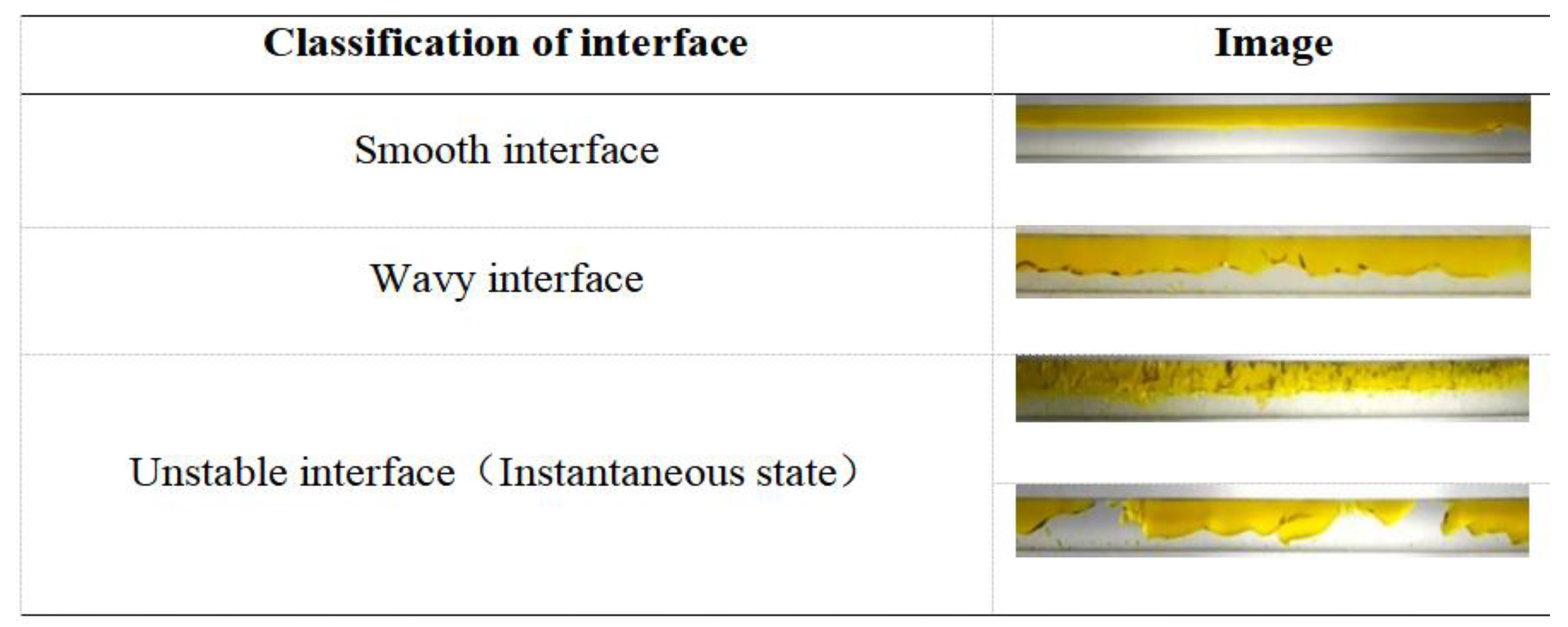
5] established an oil mixture model for the sequential transportation of gasoline and water, and conducted a simulation calculation by Phoenics, a computational fluid dynamics software. By comparing this with the sequential transportation of gasoline and diesel, the special oil–water mixture change rule for sequential transportation of gasoline and water was analyzed. Zheng et al. [
4,
6] experimentally studied the flow characteristics of the reservoir formed during the water displacing oil process of the down-dip pipe, and divided the flow patterns into smooth interface, wavy interface and unstable interface according to the oil–water interface morphology (
Figure 3).
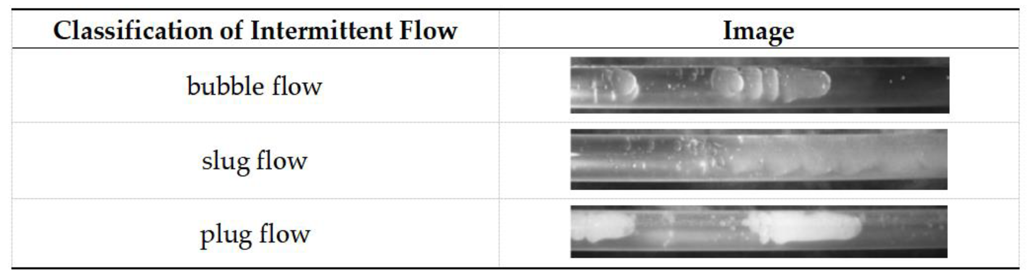
Tan et al. [
3] believe that with the increase of flow velocity, the oil–water interface will become more unstable, resulting in intermittent flow, which mainly includes bubble flow, slug flow and plug flow (
Figure 4). The research ideas and methods mainly refer to the research results of oil carrying water in the product pipeline [
73].
It is not difficult to see that there is a lack of research on the influence of complex pipeline structures such as elbow pipes, U-shaped pipes and undulating pipe segments on the emptying process in the literature. Just as some local resistance components can cause increased friction loss in the pipeline, some special pipe sections (such as undulating pipe sections) are prone to cause a large amount of oil and water mixing, which affects the overall emptying efficiency of the pipeline system. Therefore, the next study needs to consider the influence of special conditions on the emptying process, so as to avoid causing a large amount of oil mixing as much as possible.
4.2. Study on Displacement Flow Characteristics of Immiscible Fluids and Mutually-Dissolved Liquids
Emptying by water displacing oil in a mobile pipeline is due to the displacement flow between two kinds of immiscible fluids, and liquid–liquid displacement flow has a wide range of industrial applications [
10]. Taghavi et al. [
11,
12] studied the flow law of high density salt water displacing low density clear water in the pipeline under different dip angles through experiments. With the difference in stress playing a leading role in the flow process, the flow was divided into five flow patterns, and it was observed that there would be a retention layer in the pipeline under low flow velocity. Caliman et al. [
13] found through experiments that in the liquid–liquid displacement flow dominated by buoyancy, the dip angle of the pipeline had a great influence on the flow form. Hasnain et al. [
14,
15,
16] established a flow characteristic model of the displaced liquid based on the change rule of the cross-sectional area and height of the displaced liquid in liquid–liquid displacement flow over time and obtained the relationship between the front velocity and the inlet velocity of the displaced fluid. Oladosu et al. [
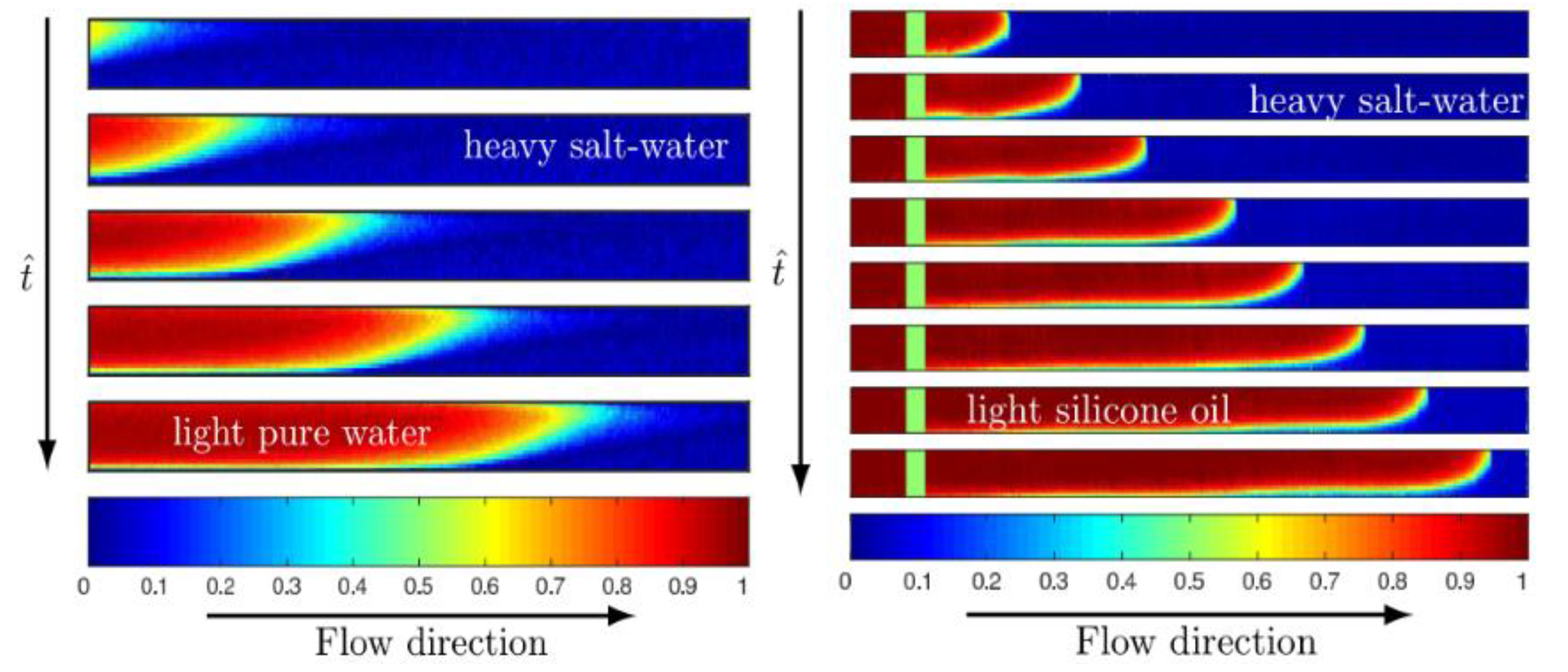
10,
17] studied the differences in displacement flows between immiscible fluids and mutually-dissolved liquids and found that the displacement flows between immiscible fluids and mutually-dissolved liquids with a high Peclet number (Pe) presented similar flow characteristics (
Figure 5). It can be seen from this figure that the two kinds of displacement flow both have clear and obvious interfaces, and the flow pattern is similar.
Chattopadhyay et al. [
18,
19,
20,
21,
22] calculated and simulated the displacement flow of liquids with different densities driven by pressure. In the early stage of displacement, the displacement rate was large and the volume fraction of the displaced liquid rapidly decreased, and after a period of time the displacement rate tended to be gentle. The water combined transport mode adopted in the product pipeline is essentially the flow process of the product oil displacing water. Diesel oil was injected into the first station to realize the replacement of oil top water. Aiming at this problem, Li [
23] and Wang et al. [
24] established a physical model for predicting the location and length of slack flow and the volume of the oil–water mixture based on the oil–oil alternating transport theory of product oil pipelines for the whole process of pipeline water commissioning.
In summary, in terms of displacement flow of immiscible fluids and mutually-dissolved liquids, the current research mainly focuses on the working conditions of a small pipe diameter, low Reynolds number and similar liquid viscosity, while there are few studies on the operating conditions applicable to the emptying by water displacing oil in mobile pipelines.
Secondly, due to the complex rheological characteristics of liquid–liquid displacement flow, the above researchers attempted to conduct a comparative study on the process by theoretical derivation, numerical simulation and experimentation. However, the situation is more complicated in the process of emptying by water displacing oil in mobile pipelines, so each condition should be considered separately to form a unified flow pattern description method and pressure drop calculation formula. The liquid–liquid mass transfer at the interface should also be considered.
4.3. Study on Mixing Characteristics of Oil–Water Two-Phase Dual Continuous Flow
According to the previous study [
7], in the initial stage of emptying by water displacing oil in the mobile pipeline, the water flows into the oil from the beginning of the pipeline at a certain speed, forming the oil–water mixing interface. As the oil–water mixing boundary migrates downstream, the oil–water interface changes constantly, and the oil–water mixing section presents stratified flow, dual continuous mixing flow and dispersed flow, respectively. Demori et al. [
25,
26] experimentally studied the mixing characteristics of oil–water dual continuous flow under different mixing flow rates, and found that the pressure drop was closely related to the oil–water dispersion characteristics and the distribution of phase separation rate and gave the critical mixing flow rate for droplet mixing. Morgan et al. [
27,
28] and Ismail et al. [
29,
30] measured the phase separation rates at different radial positions of pipelines under the condition of oil–water dual continuous flow but did not obtain the change of droplet distribution morphology. Abubakar et al. [
31,
32,
33,
34] and Zhang et al. [
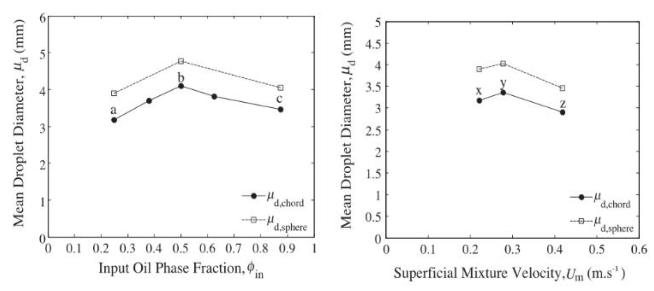
35] studied the distribution of droplets in oil–water dual continuous flow and found that the number and chord length of droplets gradually decreased with the increase of the distance between the spatial location and the oil–water interface. The particle size of the dispersed oil droplets was larger than that of the water droplets, and increasing the water phase velocity would reduce the number density of large droplets. Paolinelli et al. [
36,
37,
38,
39] observed the variation of droplet distribution during the oil–water mixing process by planar laser-induced fluorescence technology, and found that with the increase of the oil phase volume fraction or the increase of mixing speed, the average particle size of droplets increased first and then decreased (
Figure 6). At high flow rate, the number of small droplets decreased. Under different oil phase volume fractions, the higher the oil phase volume fraction, the more uniform the distribution.
It can be seen that current experimental studies mostly focus on the measurement of the interface morphology, droplet distribution and droplet velocity after the mixing formation by mixing flow rate and water content, while further studies on the mechanism of mixing generation are still needed.
4.4. Study on Dispersion Characteristics of Oil–Water Two-Phase Flow
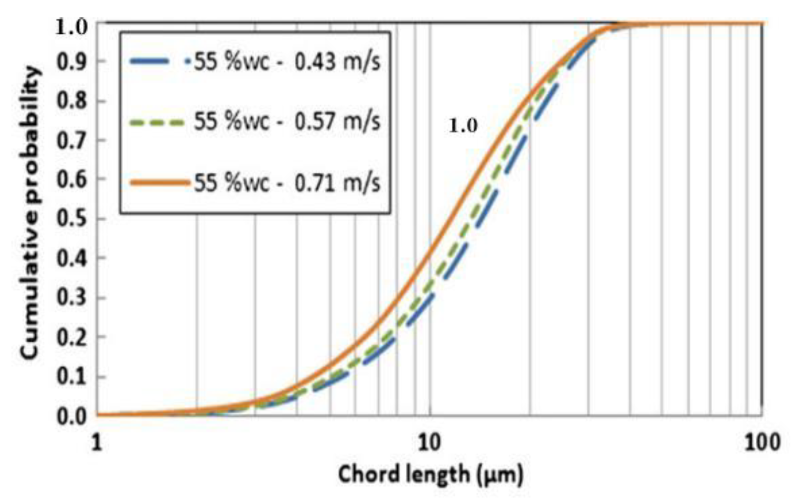
For the oil–water two-phase pipe flow, the droplet dispersion degree greatly affects the stability of the flow. Plasencia et al. [
40,
41] used Focused Beam Reflectance Measurement (FBRM) to measure droplets upstream and downstream of oil–water dispersed flow in pipes and study the effects of mixing velocity on their distribution. The results are shown in
Figure 7. It was found that droplet sizes were observed to decrease as the mixture velocity increased for a constant water cut for all the emulsions.
Schümann et al. [
42,
43,
44] used FBRM to measure droplets in six kinds of crude oil dispersion systems with different properties and believed that the formation of large droplets was the inducement factor for the occurrence of the reverse phase, and the droplet coalescence and reverse phase were not only dependent on the continuous phase viscosity but also related to the interface active substances. For the development of the droplet rupture and coalescence model, researchers mainly combined the influence of dispersed phase content, viscosity and surfactant. Based on turbulence analysis, Victor and Angeli [
45,
46] proposed a fracture and coalescence model suitable for low-dispersing phase dispersing systems. Thierry et al. [
47,
48] believed that the introduction of the dispersed phase would increase the energy dissipation rate of the turbulent field. Based on this, the turbulence partitioning model was modified to better predict the droplet distribution of the oil–water system with a high dispersed phase. Buffo et al. [
49,
50] coupled the convergence action to the Population Balance Equations (PBE), and the calculation results show that the axial variation of droplet distribution is small in a low dispersed phase system.
At present, it mainly focuses on the experimental study of the dispersion form of oil and water and the distribution of droplets in a stirred kettle and analyzes the influence of the volume fraction of the dispersed phase, inertia force and the concentration of the active agent [
33,
34,
35,
36,
37,
38,
39,
40,
41,
42,
43,
44,
45,
46,
47,
48,
49,
50]. The researchers found that the degree of dispersion greatly affected the stability of the flow [
65]. However there is a lack of research on the formation mechanism of interfacial droplet mixing under the unstable mixing flow of oil and water and the establishment of the corresponding mixing amount calculation model. Moreover, it is necessary to further study the influence of dispersed phase content on the turbulent flow field characteristics of oil–water dispersed flow.
4.5. Study on Flow Characteristics of Water Carrying Oil
At present, there are few researches on the flow characteristics of water carrying oil in mobile pipelines, mainly focusing on the oil carrying water mechanism in product oil pipelines. A large number of researches have found that parameters such as pipe diameter, oil phase velocity and pipe tilt angle have an impact on the capacity of carrying liquid.
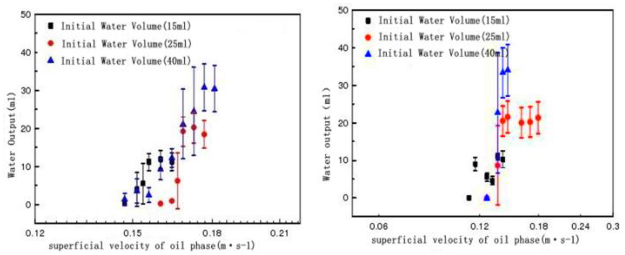
Xu et al. [
51,
52,
53] used two sets of galvanized steel pipe test systems with a diameter of 27 mm and 41 mm to conduct experiments on oil carrying water by using 0# diesel and tap water, and found the influence of a different pipe diameter on the water-output of oil carrying water in an up-dip pipeline, as shown in
Figure 8.
The left and right sides of
Figure 8 show the changes of water output with the oil phase superficial velocity at the same outlet of the upper inclined section with a diameter of 21 mm and 41 mm, respectively. It can be seen from the comparison that under the same oil phase superficial velocity, regardless of the amount of initial water volume, water output decreases with the increase of pipe diameter.
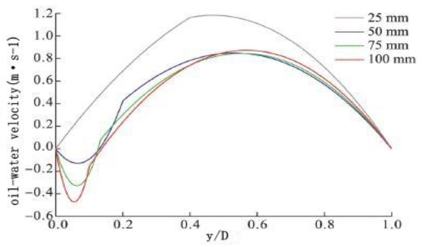
Zhang et al. [
54] conducted a comparative experimental analysis on the oil–water velocity and the water phase reflux ratio of the up dip pipe with the diameters of 25 mm, 50 mm, 75 mm and 100 mm, respectively, and the results are shown in
Figure 9 and
Table 2.
It can be seen from the data in the table that with the increase of pipe diameter the proportion of the water phase reflux also increases correspondingly, thus verifying the result proved by Xu’s experiment that the increase of pipe diameter leads to the decrease of carried water output.
Xiong et al. [
55,
56] set eight groups of loop experimental systems with the incline angles of 10°, 15°, 20°, 25°, 30°, 35°, 40° and 45°, respectively, for the visible glass tube with a diameter of 50 mm. By observing the critical velocity of the water being carried, and according to the experimental results and similar criteria, the relationship between different dip angles, pipe diameters and critical velocities is deduced. With the increase of dip angle and pipe diameter, the critical carrying-water velocity also needs to increase correspondingly, which indicates that the increase of the dip angle has a weakening effect on the capacity of oil carrying water and further proves that the increase of pipe diameter has a negative impact on the capacity of oil carrying water.
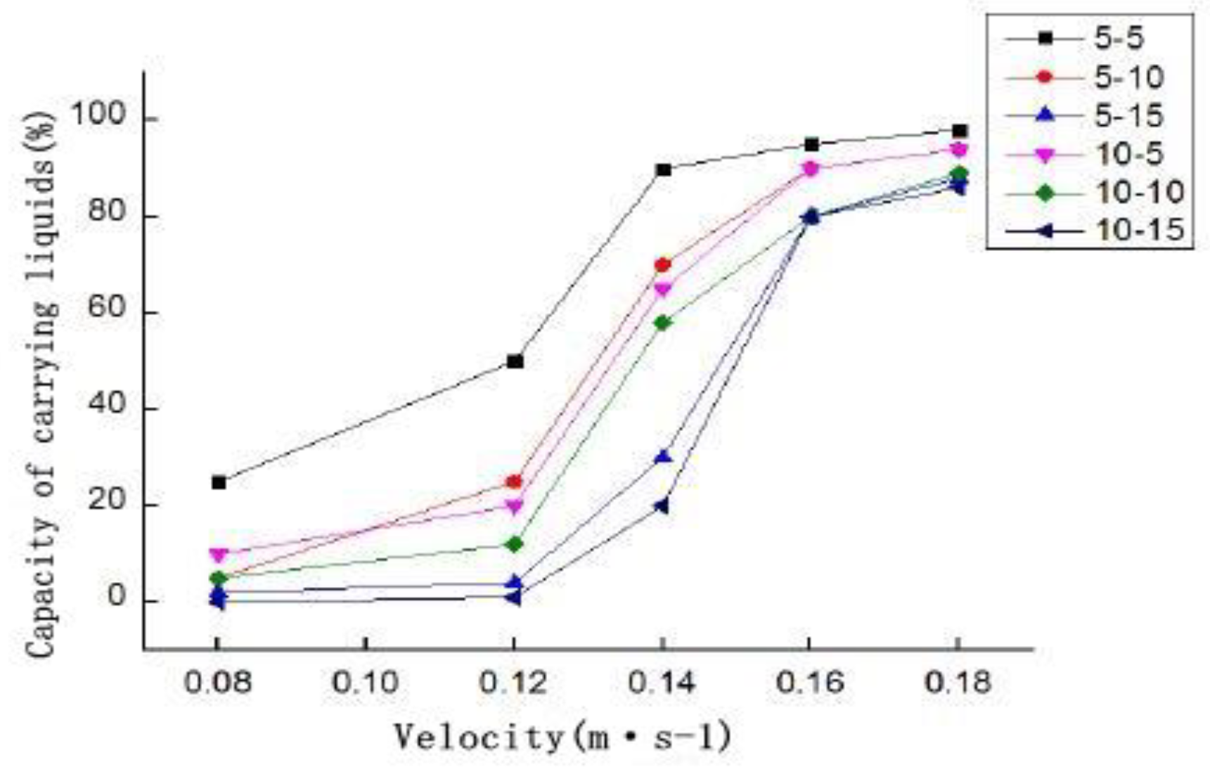
Yang et al. [
57] used the “down-dip-up-dip” pipe loop experimental system to conduct experiments on pipe segments with up-dip angles of 5°, 10° and 15° and pipe segments with down-dip angles of 5° and 10°. Under the premise of a certain amount of water volume, the experimental results are shown in
Figure 10.
As can be seen from this figure, in the case of the same downdip angle, the capacity of oil flow carrying water decreases significantly with the increase of the up-dip angle. Compared with the case of the same up-dip angle but a different down-dip angle, the capacity decreases with the increase of the down-dip angle, but the influence is small.
Being different from sequential transportation, the water carried by oil flow mainly relies on the sheer force of oil phase to carry water out of the pipeline. In view of the influence of the oil phase velocity, Xu et al. [
44,
45,
58] believe that as the superficial velocity of the oil phase increases, the velocity of the water phase will also increase, and more water will be carried out of the pipeline, indicating that the superficial velocity of the oil phase is positively correlated with the carrying-water capacity of oil flow. Zhang et al. [
54] also set up a loop experiment to study the influence of oil inlet speed on the water phase velocity and reflux ratio, and the results are shown in
Table 3. It can be found that the higher the oil inlet speed, the more the water phase flow rate will increase, the water phase reflux ratio decreases, and the water phase shows no reflux when the flow rate reaches a certain value.
Therefore, with the increase of the superficial flow velocity of the oil phase, the carrying-water capacity of oil flow will also be enhanced when the parameters such as pipe angle and pipe diameter are fixed.
Through the above research, it can be concluded that increasing the diameter of the pipeline, increasing the inclination angle and decreasing the flow rate all have a weakening effect on the water carrying capacity. On the contrary, reducing pipe diameter, decreasing inclination angle and increasing velocity will enhance water carrying capacity.
The research on oil carrying water is still based on the theory of sequential transmission of a product oil pipeline, but the emptying by water displacing oil in a mobile pipeline is a process of water carrying oil, and the effect of gravity and buoyancy is opposite to that of oil carrying water. Therefore, the influence of dip angle, diameter and velocity of a mobile pipeline on the ability of water flow to carry oil during emptying is unknown and worthy of further exploration.
5. Discussions
Through the analysis of the above research status at home and abroad, it is found that although a series of valuable researches has been carried out in the experiment and theory of emptying by water displacing oil in mobile pipelines, it is not difficult to see that most of the researches still simply apply the oil–oil alternating transport theory of product oil pipelines and do not thoroughly study the water–oil flow characteristics in the emptying process from the perspective of oil–water two-phase flow.
1. From the perspective of research on the formation mechanism of oil–water mixing, researchers regard emptying by water displacing oil as the sequential transport treatment of product oil, and there is no consensus on the formation mechanism of the oil–water mixture in the process of emptying. Zhang et al. [
7] believe that in the process of sequential transportation, due to the small velocity difference between the oil phase and the water phase, the distribution of oil and water in the oil–water mixing section is not “uniform agitation” but “relative aggregation”. However, Zheng et al. [
6] believe that in the process of emptying by the water displacing oil, due to the relatively static oil phase, the oil phase was broken and evenly mixed in the water phase. The formation, development and physical form of the oil–water mixture in the process of emptying are very different from the characteristics of oil sequential transportation, and the calculation of the oil–water mixture quantity cannot adopt the model of oil sequential transportation. When the oil is transported sequentially, the two adjacent oil products are miscible, and the flow process is generally treated as a single-phase flow with continuous density changes. Due to the insolubility of oil and water, the oil–water mixing section presents oil–water two-phase flow with different flow patterns, and the flow characteristics are significantly different from single-phase flow. Therefore, it can be studied from the following three directions.
The first direction is study on the interface morphology and flow field characteristics of oil–water two-phase layered flow. Since the oil–water mixing section can form three different flow patterns, namely stratified flow, dual continuous flow and dispersed flow, the oil–water two-phase flow characteristics under different flow patterns are quite different, so it is necessary to use different physical models to describe the oil–water two-phase flow. Stratified flow is the most common and basic flow pattern in oil–water two-phase flow, which is the basis of studying oil–water flow characteristics under other flow patterns. Therefore, in order to obtain the oil–water mixing mechanism and flow characteristics of emptying by water displacing oil, it is necessary to first study the interface morphology and flow field characteristics of oil–water two-phase stratified flow and lay a foundation for the subsequent research of dual continuous mixed flow and dispersed flow.
The second direction is study on local mixing characteristics at the interface of oil–water two-phase dual continuous flow. In stratified flow, the velocity of the two phases of oil and water is different, the interfacial wave is easy to deform under the action of drag force and the windward side gradually tends to the vertical flow direction. At this time, the interfacial tension hindering the change of the interface waveform only exists in the leeward side (axial). If the drag force is greater than the interfacial tension component force, the droplet will detach. With the increase of flow velocity, the mixing of droplets gradually appears at the interface of the oil–water stratified flow, forming a dual continuous flow with local mixing at the interface, which makes the oil–water mixing increase rapidly. Therefore, based on the study of the interface morphology and flow field characteristics of oil–water stratified flow, it is necessary to study the local mixing characteristics of the oil–water two-phase interface.
The third direction is study on droplet distribution and flow characteristics of oil–water two-phase dispersed flow. In the process of emptying by water displacing oil, with the increase of water phase velocity the separation and mixing of oil and water droplets gradually appear at the oil–water stratified flow interface, and the mixed droplets partially diffuse to the oil–water phase, forming a dual continuous flow with local mixing at the interface. With the further increase of water velocity, the thickness of the droplet layer increases until the droplet layer penetrates through the tube wall and forms a dispersed flow. The formation and evolution of the dispersion flow pattern are directly determined by the droplet rupture, polymerization and radial movement. The size, quantity, interfacial concentration and distribution of droplets have important effects on oil–water mixing volume, viscosity and pressure drop, etc. The design of terminal oil–water separation equipment also depends on the grain size and distribution law of oil and water.
2. From the perspective of the study of displacement flow in immiscible fluids, due to the complexity of displacement flow, the liquid–liquid interface is usually assumed to be a solid–liquid interface with slip velocity [
11,
12,
13,
14,
15,
16]. The dynamic evolution of the liquid–liquid interface under the action of flow field and the study of droplet detachment, deformation and mixing characteristics at the interface are lacking, and the mass transfer between liquid and liquid at the interface is ignored. At present, the computational model of displacement flow characteristics mainly describes liquid–liquid two-phase flow, ignoring the interaction between liquid–liquid two-phase flow, displacement fluid and displaced fluid and ignoring the unsteady flow of displacement flow.
Therefore, the unsteady flow characteristics of the oil–water mixture can be further studied for emptying by water displacing oil in mobile pipelines. In the process of water displacing oil, the oil–water mixing interface and the oil–water mixing section move in the pipe, and the length, position, flow pattern and flow characteristics of the mixing section change constantly with time, so that the energy supply and energy consumption of the system constantly change. The pipeline system has been in an unsteady flow until the oil–water mixture is completely discharged from the pipeline. Emptying by water displacing oil is a complicated coupled process of oil–water two-phase flow and mass transfer. It is an unsteady flow problem in which oil–water two-phase flow is coupled with a pure oil phase and a pure water phase. Therefore, in order to clarify the evolution law of oil–water interface formation, development and migration, the research needs to establish the oil–water-mixed oil tracking model and obtain the oil–water mechanism and flow characteristics of water displacing oil; it is also necessary to study the unsteady flow characteristics of water displacing oil and oil–water mixture on the basis of the studies of oil–water two-phase stratified flow, dual continuous mixing flow and dispersed flow.
3. From the perspective of the study of the characteristics of water carrying oil, it is very different from the existing oil–water two-phase pipe flow; in traditional research, the oil phase and the water phase enter the pipeline at a certain flow rate and phase holdup [
7,
18,
23,
24]. However, after the oil is injected into the pipeline in the process of emptying by water displacing oil, the oil volume in the pipeline will no longer increase. With the movement of oil accumulation, the oil content of the different sections of the pipeline will change at different times. At the same time, at the entrance of the pipeline, only the water phase enters the pipeline with a certain flow rate, and the momentum of oil accumulation in the pipeline all comes from the interaction between the oil and water phases. The flow rate of oil accumulation and the phase holdup are unknown. There are many complex pipeline structures, such as elbow pipe and undulating pipe sections, so there is a big difference in oil mixing amount predicted by using the existing oil mixing model.
Therefore it needs the study of oil accumulation and flow characteristics in topographic relief pipes. In the process of emptying by water displacing oil, the oil phase and the water phase are insoluble and there are density and polarity differences between them, which makes it difficult to form a stable emulsion. In a topographic relief pipe, due to the action of buoyancy, liquid interface instability and wall backflow, the oil phase gathers at the high point of the pipeline and forms a liquid accumulation, which is difficult to carry and discharge by water flow; as a result the oil cannot be completely discharged from the pipeline, greatly reducing the emptying efficiency. Therefore it is necessary to establish the liquid layer thickness model and the calculation model of the critical flow velocity and reveal the mechanism of water flow carrying oil. It is necessary to study the characteristics of oil accumulation and flow in topographic relief pipes.
6. Conclusions
In this paper, the literature related to the oil–water flow characteristics of emptying by water displacing oil in mobile pipelines in recent years was systematically reviewed. Starting from macro and micro perspectives, domestic and foreign scholars have carried out research on the emptying characteristics of mobile pipelines, the displacement flow characteristics of immiscible fluids, the mixing characteristics of oil–water two-phase dual continuous flow, the dispersion characteristics of oil–water two-phase flow and the characteristics of oil carrying water. The oil–water mixing model of emptying by water displacing oil was established, and the relationship between macroscopic quantity (flow pattern, pressure drop and water content) and microscopic quantity (local flow field and droplet dispersion pattern, etc.) under each flow type was established. The influence of pipeline diameter, oil phase velocity and pipeline tilt angle on the capacity of carrying fluid was analyzed.
Secondly, the shortcomings of research methods such as treating the emptying by water displacing oil as the sequential transportation of product oil, assuming the liquid–liquid interface as being the solid–liquid interface with the slip speed and treating the oil accumulation as the additive amount were analyzed in depth. It is concluded that the oil–water mixed section presents different flow patterns of oil–water two-phase flow in the process of emptying, and the flow characteristics are significantly different from single-phase flow. The mass transfer between liquid–liquid at the interface and the coupling between liquid–liquid two-phase flow and displacing fluid and displaced fluid exist objectively. The momentum of oil accumulation in the pipeline all comes from the interaction between the oil and water phases, and the amount of oil accumulation will not increase.
Finally, considering that the essence of the emptying problem by water displacing oil is the oil–water two-phase unsteady displacement flow, the development dynamic analysis is made in combination with the shortcomings of the current research situation, and the next step can be studied from five directions, including the evolution characteristics of the oil–water phase interface, the unsteady flow characteristics of the oil–water mixture and the accumulation and flow characteristics of oil in the topographic relief pipe. This paper provides reference and thought for further research on oil–water flow characteristics of emptying by water displacing oil in mobile pipelines.


