
Power Generation with Renewable Energy and Advanced Supercritical CO2 Thermodynamic Power Cycles: A Review

Abstract
:1. Introduction and Motivation
- (i)
- In Section 2, the superior thermal–physical properties of CO2 are outlined, along with the benefits of incorporating CO2 in supercritical power generation cycles.
- (ii)
- Section 3 demonstrates the advantage characteristics and categorizations of renewable energy as a promising source of heat, encompassing biomass, solar, geothermal and waste heat.
- (iii)
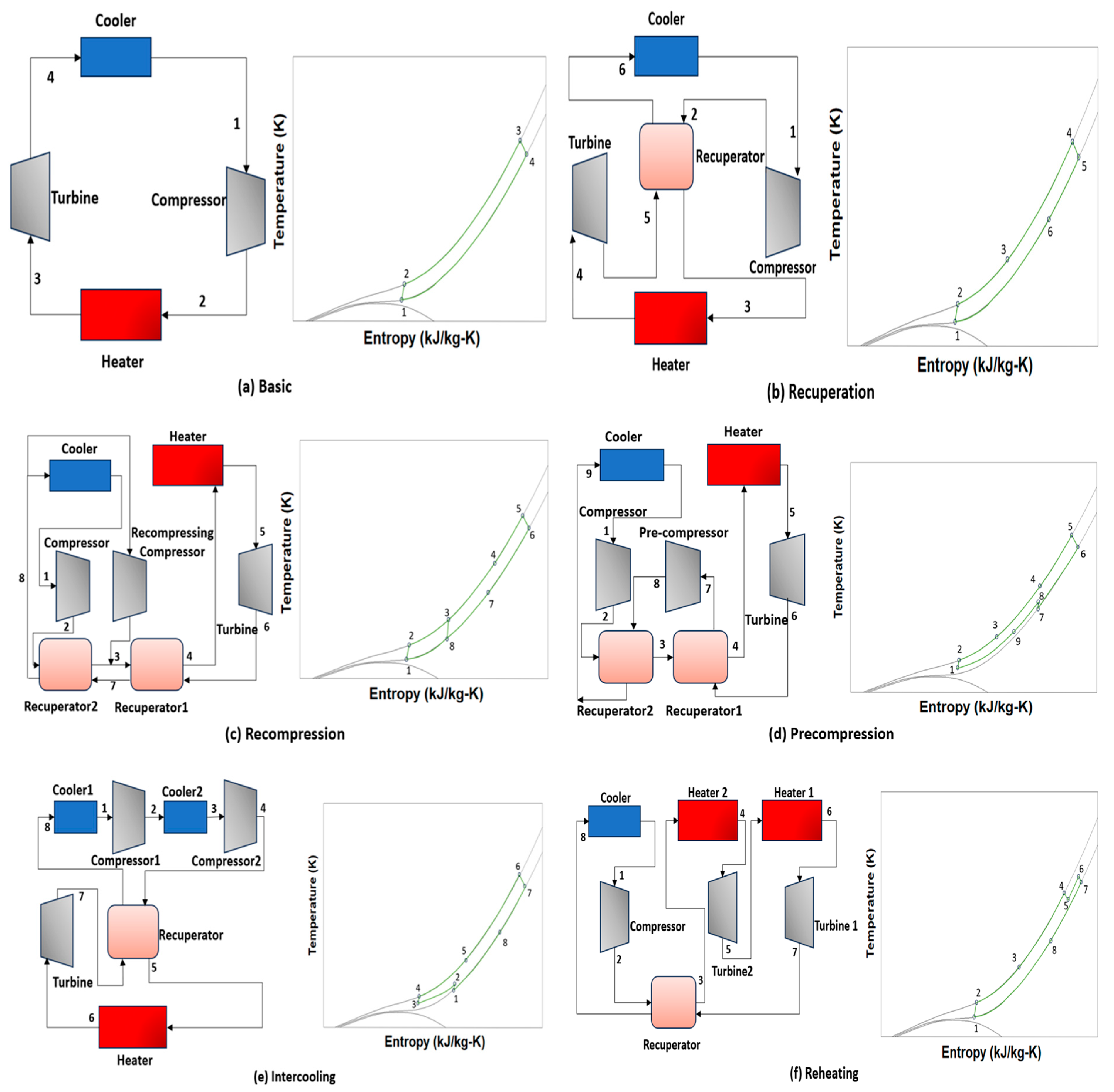
- In Section 4, representative S-CO2 cycles are summarized with emphasis on features of each layout, T-S diagrams and thermodynamic equations.
- (iv)
- In Section 5, a review of recent applications of S-CO2 renewable power systems is presented, including S-CO2 for biomass power systems, S-CO2 cycle for concentrating solar power systems, S-CO2 cycle for geothermal power systems and S-CO2 cycle for waste heat recovery. This focuses on various technologies, operating conditions and efficiencies. In addition, the barriers to S-CO2 technology are also concluded.
2. Superior Thermal–Physical Properties of CO2
3. Superior Characteristics of Renewable Energy
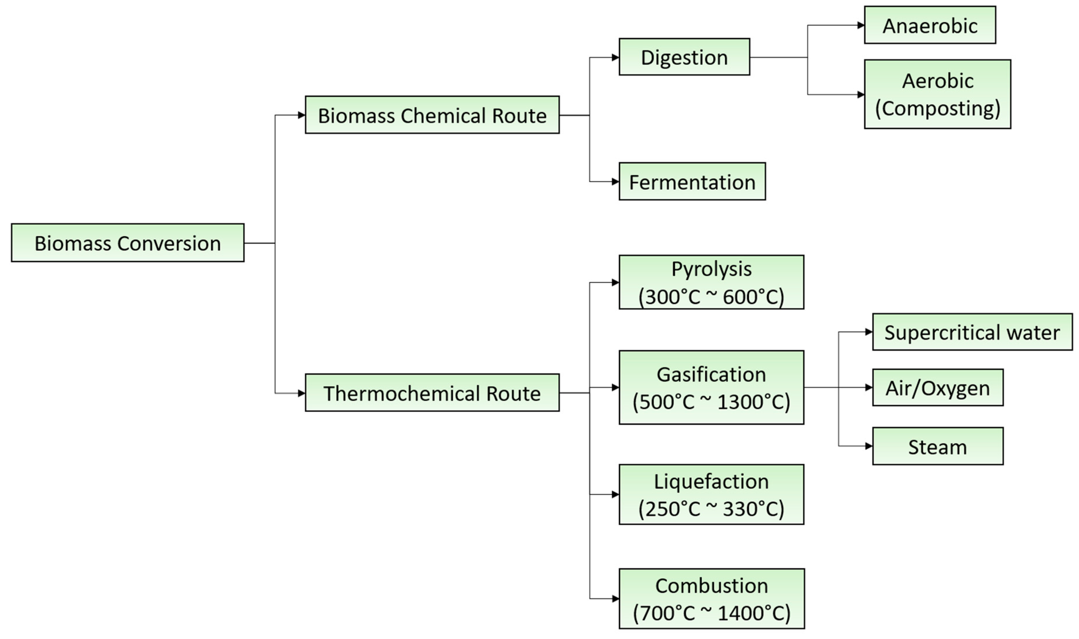
3.1. Biomass
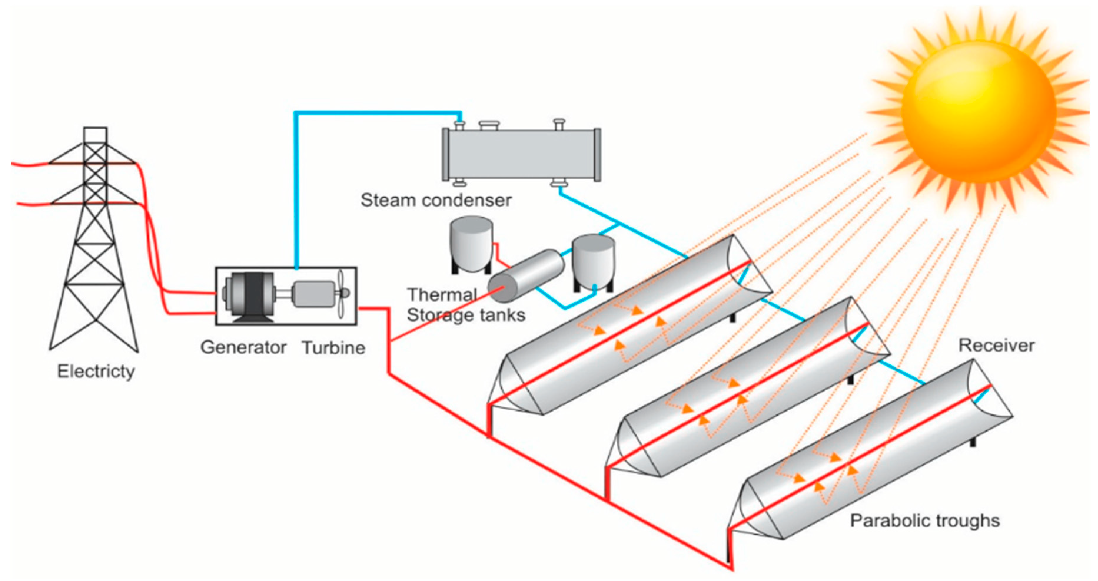
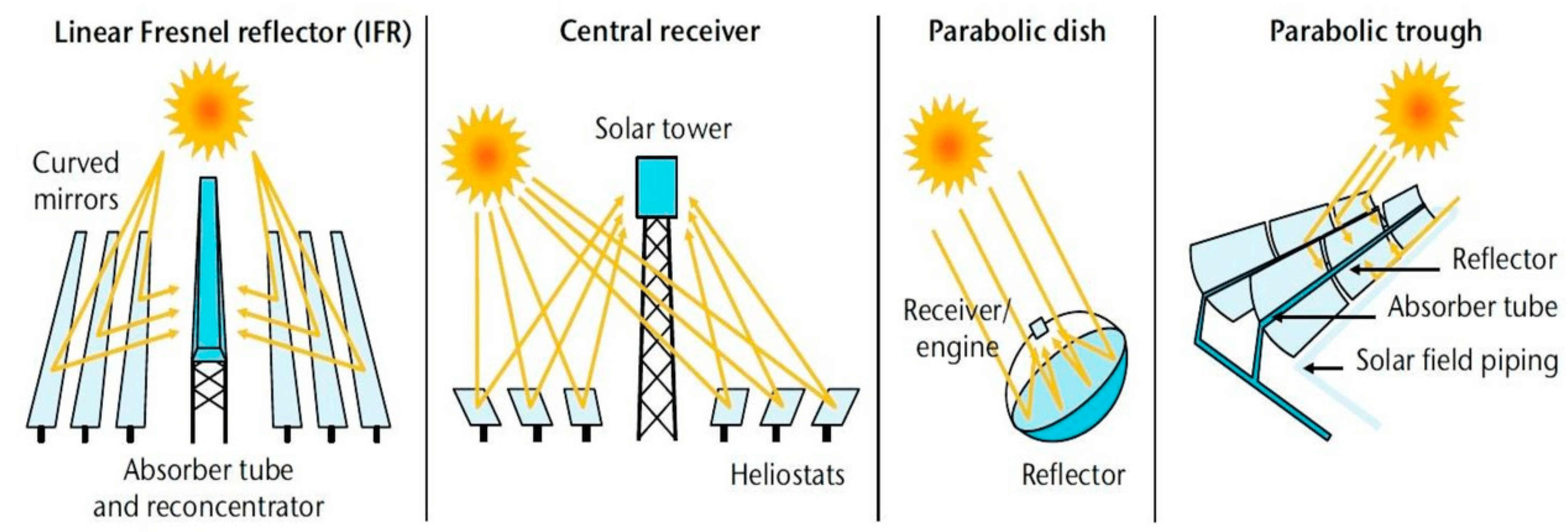
3.2. Solar Power
3.3. Geothermal Resource
3.4. Waste Heat Resource
4. S-CO2 Layouts
5. Application Status of S-CO2 Renewable Power Systems
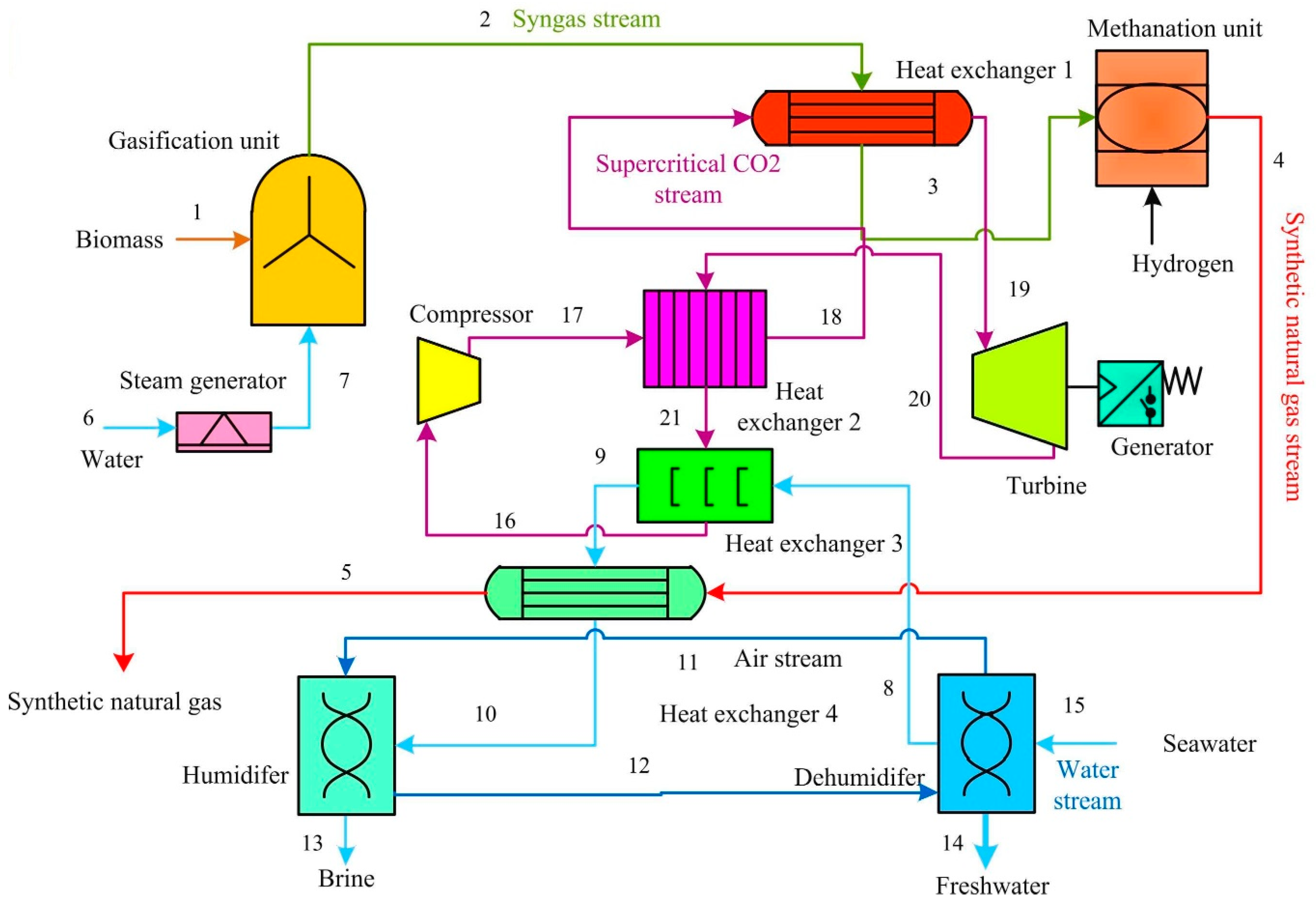
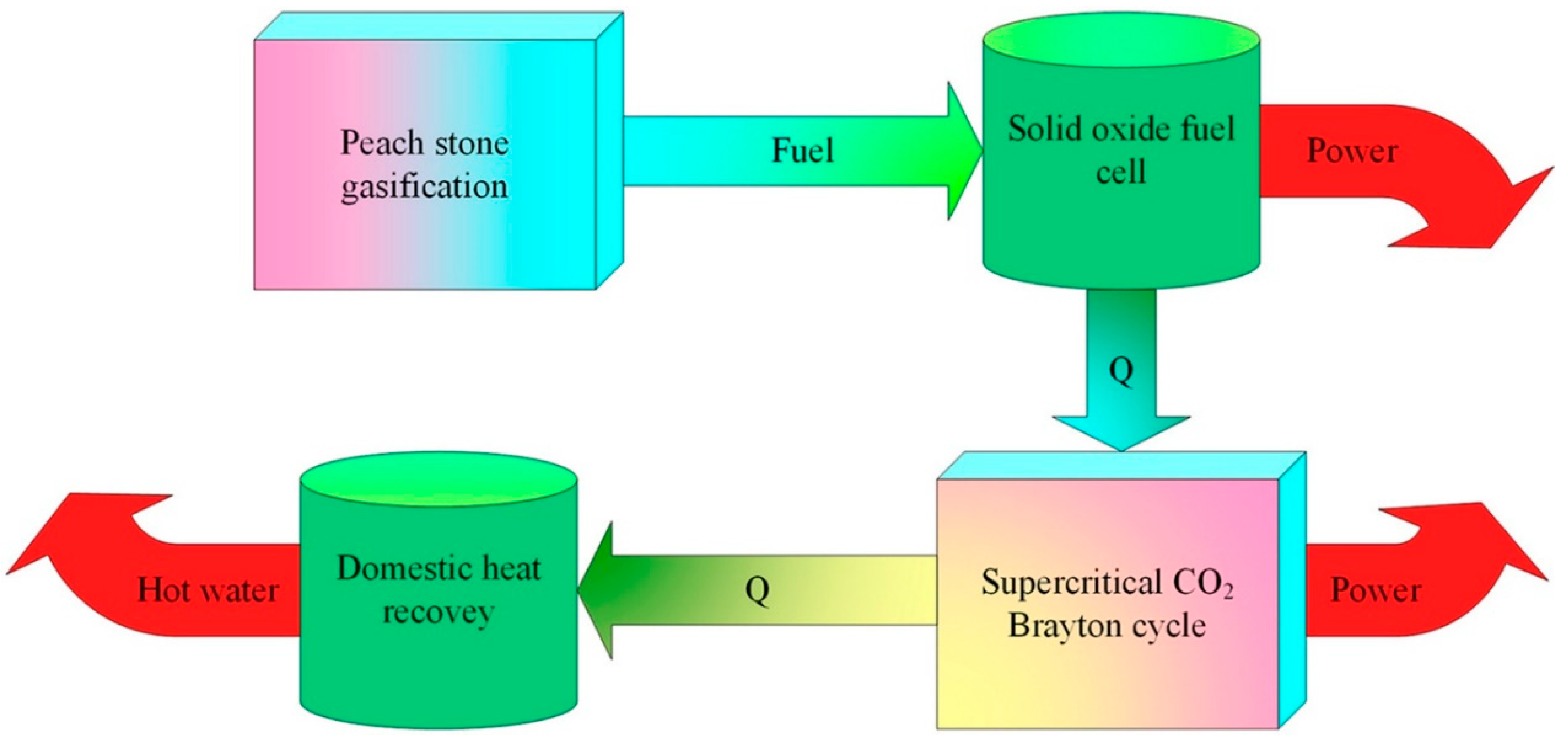
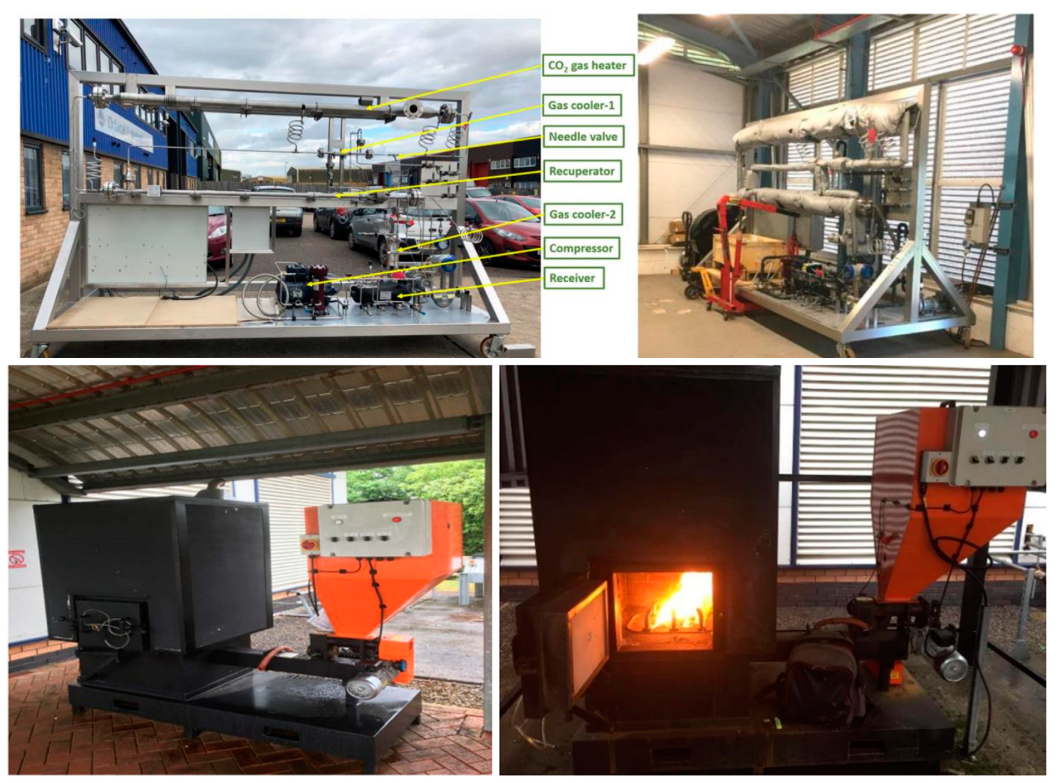
5.1. S-CO2 for Biomass Power Systems
5.2. S-CO2 Cycle for Concentrating Solar Power Systems
5.3. S-CO2 Cycle for Geothermal Power Systems


| Ref. | Year | Technology | Tsource (°C) | Pmax (MPa) | Pmin (Mpa) | Wnet (kW) | ⴄth | |
|---|---|---|---|---|---|---|---|---|
| Ezekiel et al. [101] | 2019 | CO2 EGR-CPG | 150 | 30 | 1187 | |||
| Ruiz-Casanova et al. [100] | 2020 | Simple Brayton cycle | 150 | 23.942 | 7.904 | 725.34 | 10.71% | |
| Recuperated Brayton cycle | 17.919 | 8 | 748.95 | 11.1% | ||||
| Intercooled Brayton cycle | 24.74 | 7.939 | 719.31 | 10.62% | ||||
| Intercooled recuperated Brayton cycle | 18.332 | 8.13 | 779.99 | 11.51% | ||||
| Wang [92] | 2018 | Simply sCO₂ cycle | 195 | 22.5 | 7.8 | 2758 | 13.92% | |
| Recuperative sCO₂ cycle | 2584 | 8.92% | ||||||
| sCO2 cycle with pre-compression and inter-cooling | 3194 | 11.02% | ||||||
| sCO2 cycle with reheating | 5970 | 10.3% | ||||||
| sCO2 Cycle with pre-compression, inter-cooling and reheating | 6904 | 11.91% | ||||||
| Wright [102] | 2017 | sCO2 cycle with recompression, reheating and intercooling | >160 | 22.2 | 8.62 | 2369 | 15% | |
| sCO2/10% Butane cycle with recompression, reheating and intercooling | 2675 | 18% | ||||||
| Glos et al. [105] | 2019 | s-CO2 Rankine cycle | >102 | 24.5 | 6 | 3240 | 5% | |
| Levy et al. [106] | 2018 | Direct turbine expansion system | 225 | 14.5 | 8.34 | 30,000 | - | |
| Tagliaferri et al. [107] | 2022 | Direct sCO2 cycle | District heating system located between turbine: T hot water = 35 °C T cold water = 60 °C Recovery heat exchanger located after the production well: T hot water = 50 °C T cold water = 80 °C 35 °C ≤ Tinjection ≤ 55 °C | 1630 | - | |||
| Indirect sCO2 cycle with ORC (binary cycle) | 2612 | - | ||||||
| Direct S-CO2 with cogeneration | District heating system located between turbine stages | 1556 | - | |||||
| District heating system located after the production well | 1055 | - | ||||||
| Combined direct sCO2 with ORC | Recovery heat exchanger located before the injection well | 2918 | - | |||||
| Recovery heat exchanger located after the production well | 2663 | - | ||||||
| Sun et al. [108] | 2023 | T-CO2 Rankine Cycle + power and heat generation unit | 1966 | 20 | 5.73 | 67.5 | 42.5% | |
5.4. S-CO2 Cycle for Waste Heat Recovery
5.5. Barriers to Take Up of the S-CO2 Technology
- Although a small power generation system can be constructed owing to the high density of CO2, it allows for more compact turbine, compressor and heat exchanger components. The design, production and selection of turbomachinery is still a challenge for operating CO2 in a wide range of temperatures and pressures.
- Enhancing the efficiency of the system via the improvement in heat exchangers remains a compelling aspect for the successful operation of a S-CO2 Brayton cycle, given the presence of at least two heat exchangers in the basic cycle.
- Insufficient practical experience and performance data from both experimental and commercial applications to provide solid support for applying this technology in the area of renewable energy.
6. Conclusions
Author Contributions
Funding
Data Availability Statement
Acknowledgments
Conflicts of Interest
Nomenclature
| Cp | Specific heat at constant pressure, J/(kg.K) |
| h | Enthalpy, J/kg |
| Mass flow rate, kg/s | |
| P | Pressure, Pa |
| Q | Heat transfer, W |
| T | Temperature, K |
| W | Power, W |
| Greek letters | |
| η | Efficiency |
| Ꜫ | Effectiveness |
| Subscripts | |
| C | Cooler |
| H | Heater, High |
| L | Low |
| P | Compressor |
| Rec | Recuperator |
| s | Isentropic |
| th | Thermal |
| T | Turbine |
References
- Energy Institute. Statistical Review of World Energy; Energy Institute: London, UK, 2023. [Google Scholar]
- Schuster, A.; Karellas, S.; Kakaras, E.; Spliethoff, H. Energetic and Economic Investigation of Organic Rankine Cycle Applications. Appl. Therm. Eng. 2009, 29, 1809–1817. [Google Scholar] [CrossRef]
- Tchanche, B.F.; Lambrinos, G.; Frangoudakis, A.; Papadakis, G. Low-Grade Heat Conversion into Power Using Organic Rankine Cycles—A Review of Various Applications. Renew. Sustain. Energy Rev. 2011, 15, 3963–3979. [Google Scholar] [CrossRef]
- Coco-Enríquez, L.; Muñoz-Antón, J.; Martínez-Val, J.M. New Text Comparison between CO2 and Other Supercritical Working Fluids (Ethane, Xe, CH4 and N2) in Line- Focusing Solar Power Plants Coupled to Supercritical Brayton Power Cycles. Int. J. Hydrogen Energy 2017, 42, 17611–17631. [Google Scholar] [CrossRef]
- Manzolini, G.; Binotti, M.; Bonalumi, D.; Invernizzi, C.; Iora, P. CO2 Mixtures as Innovative Working Fluid in Power Cycles Applied to Solar Plants. Techno-Economic Assessment. Sol. Energy 2019, 181, 530–544. [Google Scholar] [CrossRef]
- Besarati, S.M.; Yogi Goswami, D. Analysis of Advanced Supercritical Carbon Dioxide Power Cycles with a Bottoming Cycle for Concentrating Solar Power Applications. J. Sol. Energy Eng. 2013, 136, 010904. [Google Scholar] [CrossRef]
- Sulzer, G. Verfahren zur erzeugung von arbeit aus warme. Swiss Pat. 1950, 269599, 15. [Google Scholar]
- Feher, E.G. The supercritical thermodynamic power cycle. Energy Convers. 1968, 8, 85–90. [Google Scholar] [CrossRef]
- Angelino, G. Perspectives for the Liquid Phase Compression Gas Turbine. J. Eng. Power 1967, 89, 229–236. [Google Scholar] [CrossRef]
- Angelino, G. Carbon Dioxide Condensation Cycles for Power Production. J. Eng. Power 1968, 90, 287–295. [Google Scholar] [CrossRef]
- Angelino, G. Real Gas Effects in Carbon Dioxide Cycles. In Proceedings of the ASME 1969 Gas Turbine Conference and Products Show, Cleveland, OH, USA, 9–13 March 1969. [Google Scholar] [CrossRef]
- Brun, K.; Friedman, P.; Dennis, R. Fundamentals and Applications of Supercritical Carbon Dioxide (SCO2) Based Power Cycles; Woodhead Publishing: Cambridge, UK, 2017. [Google Scholar]
- Le Moullec, Y. Conceptual Study of a High Efficiency Coal-Fired Power Plant with CO2 Capture Using a Supercritical CO2 Brayton Cycle. Energy 2013, 49, 32–46. [Google Scholar] [CrossRef]
- Mecheri, M.; Le Moullec, Y. Supercritical CO2 Brayton Cycles for Coal-Fired Power Plants. Energy 2016, 103, 758–771. [Google Scholar] [CrossRef]
- Xu, J.; Wang, X.; Sun, E.; Li, M. Economic Comparison between SCO2 Power Cycle and Water-Steam Rankine Cycle for Coal-Fired Power Generation System. Energy Convers. Manag. 2021, 238, 114150. [Google Scholar] [CrossRef]
- Wang, Z.; Xu, J.; Wang, T.; Miao, Z.; Wang, Q.; Liu, G. Performance of SCO2 Coal-Fired Power Plants at Various Power Capacities. J. Clean. Prod. 2023, 416, 137949. [Google Scholar] [CrossRef]
- Ahn, Y.; Bae, S.J.; Kim, M.; Cho, S.K.; Baik, S.; Lee, J.I.; Cha, J.E. Review of Supercritical CO2 Power Cycle Technology and Current Status of Research and Development. Nucl. Eng. Technol. 2015, 47, 647–661. [Google Scholar] [CrossRef]
- Dostal, V.; Driscoll, M.J.; Hejzlar, P. A Supercritical Carbon Dioxide Cycle for Next Generation Nuclear Reactors. Doctoral Dissertation, Department of Nuclear Engineering, Massachusetts Institute of Technology, Cambridge, MA, USA, 2004. [Google Scholar]
- Moisseytsev, A.; Sienicki, J.J. Investigation of Alternative Layouts for the Supercritical Carbon Dioxide Brayton Cycle for a Sodium-Cooled Fast Reactor. Nucl. Eng. Des. 2009, 239, 1362–1371. [Google Scholar] [CrossRef]
- Wright, S.A.; Conboy, T.M.; Radel, R.; Rochau, G.E. Modeling and Experimental Results for Condensing Supercritical CO2 Power Cycles; OSTI OAI (U.S. Department of Energy Office of Scientific and Technical Information): Oak Ridge, TN, USA, 2011. [CrossRef]
- Yoon, H.J.; Ahn, Y.; Lee, J.I.; Addad, Y. Potential Advantages of Coupling Supercritical CO2 Brayton Cycle to Water Cooled Small and Medium Size Reactor. Nucl. Eng. Des. 2012, 245, 223–232. [Google Scholar] [CrossRef]
- World Nuclear Performance Report 2023. Available online: https://www.world-nuclear.org/getmedia/0156a8d7-01c6-42d9-97be-3f04f34cb8fa/performance-report-2023-final.pdf.aspx (accessed on 1 September 2023).
- Kumar, P.; Srinivasan, K. Carbon Dioxide Based Power Generation in Renewable Energy Systems. Appl. Therm. Eng. 2016, 109, 831–840. [Google Scholar] [CrossRef]
- Crespi, F.; Gavagnin, G.; Sánchez, D.; Martínez, G.S. Supercritical Carbon Dioxide Cycles for Power Generation: A Review. Appl. Energy 2017, 195, 152–183. [Google Scholar] [CrossRef]
- Marchionni, M.; Bianchi, G.; Tassou, S.A. Review of Supercritical Carbon Dioxide (SCO2) Technologies for High-Grade Waste Heat to Power Conversion. SN Appl. Sci. 2020, 2, 611. [Google Scholar] [CrossRef]
- White, M.T.; Bianchi, G.; Chai, L.; Tassou, S.A.; Sayma, A.I. Review of Supercritical CO2 Technologies and Systems for Power Generation. Appl. Therm. Eng. 2021, 185, 116447. [Google Scholar] [CrossRef]
- Guo, J.Q.; Li, M.J.; He, Y.L.; Jiang, T.; Ma, T.; Xu, J.L.; Cao, F. A Systematic Review of Supercritical Carbon Dioxide(S-CO2) Power Cycle for Energy Industries: Technologies, Key Issues, and Potential Prospects. Energy Convers. Manag. 2022, 258, 115437. [Google Scholar] [CrossRef]
- Ge, Y.T.; Tassou, S.A.; Santosa, I.D.; Tsamos, K. Design Optimisation of CO2 Gas Cooler/Condenser in a Refrigeration System. Appl. Energy 2015, 160, 973–981. [Google Scholar] [CrossRef]
- Dostal, V.; Hejzlar, P.; Driscoll, M.J. The Supercritical Carbon Dioxide Power Cycle: Comparison to Other Advanced Power Cycles. Nucl. Technol. 2006, 154, 283–301. [Google Scholar] [CrossRef]
- Garg, P.; Kumar, P.; Srinivasan, K. Supercritical Carbon Dioxide Brayton Cycle for Concentrated Solar Power. J. Supercrit. Fluids 2013, 76, 54–60. [Google Scholar] [CrossRef]
- Chen, H.; Goswami, D.Y.; Stefanakos, E.K. A Review of Thermodynamic Cycles and Working Fluids for the Conversion of Low-Grade Heat. Renew. Sustain. Energy Rev. 2010, 14, 3059–3067. [Google Scholar] [CrossRef]
- Chen, Y.; Lundqvist, P.; Johansson, A.; Platell, P. A Comparative Study of the Carbon Dioxide Transcritical Power Cycle Compared with an Organic Rankine Cycle with R123 as Working Fluid in Waste Heat Recovery. Appl. Therm. Eng. 2006, 26, 2142–2147. [Google Scholar] [CrossRef]
- Basu, P. Biomass Gasification, Pyrolysis and Torrefaction: Practical Design and Theory; Elsevier Academic Press: London, UK, 2018. [Google Scholar]
- Pospíšil, J.; Lisý, M.; Špiláček, M. Optimalization of Afterburner Channel in Biomass Boiler Using CFD Analysis. Acta Polytech. 2016, 56, 379–387. [Google Scholar] [CrossRef]
- Biomass Strategy. 2023. Available online: https://assets.publishing.service.gov.uk/government/uploads/system/uploads/attachment_data/file/1178897/biomass-strategy-2023.pdf (accessed on 1 September 2023).
- Aboelwafa, O.; Fateen, S.E.K.; Soliman, A.; Ismail, I.M. A Review on Solar Rankine Cycles: Working Fluids, Applications, and Cycle Modifications. Renew. Sustain. Energy Rev. 2018, 82, 868–885. [Google Scholar] [CrossRef]
- Global Solar Energy Share in Electricity Mix. 2022. Statista. Available online: https://www.statista.com/statistics/1302055/global-solar-energy-share-electricity-mix/ (accessed on 1 September 2023).
- Tzivanidis, C.; Bellos, E.; Antonopoulos, K.A. Energetic and Financial Investigation of a Stand-Alone Solar-Thermal Organic Rankine Cycle Power Plant. Energy Convers. Manag. 2016, 126, 421–433. [Google Scholar] [CrossRef]
- Tchanche, B.F.; Pétrissans, M.; Papadakis, G. Heat Resources and Organic Rankine Cycle Machines. Renew. Sustain. Energy Rev. 2014, 39, 1185–1199. [Google Scholar] [CrossRef]
- Turchi, C.S.; Ma, Z.; Neises, T.W.; Wagner, M.J. Thermodynamic Study of Advanced Supercritical Carbon Dioxide Power Cycles for Concentrating Solar Power Systems. J. Sol. Energy Eng. 2013, 135, 041007. [Google Scholar] [CrossRef]
- Caccia, M.; Tabandeh-Khorshid, M.; Itskos, G.; Strayer, A.R.; Caldwell, A.S.; Pidaparti, S.; Singnisai, S.; Rohskopf, A.D.; Schroeder, A.M.; Jarrahbashi, D.; et al. Ceramic–Metal Composites for Heat Exchangers in Concentrated Solar Power Plants. Nature 2018, 562, 406–409. [Google Scholar] [CrossRef] [PubMed]
- Patil, V.R.; Kiener, F.; Grylka, A.; Steinfeld, A. Experimental Testing of a Solar Air Cavity-Receiver with Reticulated Porous Ceramic Absorbers for Thermal Processing at above 1000 °C. Sol. Energy 2021, 214, 72–85. [Google Scholar] [CrossRef]
- Mahlia, T.M.I.; Syaheed, H.; Abas, A.E.P.; Kusumo, F.; Shamsuddin, A.H.; Ong, H.C.; Bilad, M.R. Organic Rankine Cycle (ORC) System Applications for Solar Energy: Recent Technological Advances. Energies 2019, 12, 2930. [Google Scholar] [CrossRef]
- Loni, R.; Mahian, O.; Najafi, G.; Sahin, A.Z.; Rajaee, F.; Kasaeian, A.; Mehrpooya, M.; Bellos, E.; le Roux, W.G. A Critical Review of Power Generation Using Geothermal-Driven Organic Rankine Cycle. Therm. Sci. Eng. Prog. 2021, 25, 101028. [Google Scholar] [CrossRef]
- DiPippo, R. Geothermal Power Plants; Butterworth-Heinemann: Oxford, UK, 2012. [Google Scholar]
- Liu, Q.; Duan, Y.; Yang, Z. Performance Analyses of Geothermal Organic Rankine Cycles with Selected Hydrocarbon Working Fluids. Energy 2013, 63, 123–132. [Google Scholar] [CrossRef]
- Quoilin, S.; Broek, M.V.D.; Declaye, S.; Dewallef, P.; Lemort, V. Techno-Economic Survey of Organic Rankine Cycle (ORC) Systems. Renew. Sustain. Energy Rev. 2013, 22, 168–186. [Google Scholar] [CrossRef]
- Reddy, C.; Naidu, S.V.; Rangaiah, G.P. Waste heat recovery methods and technologies: There is significant potential for recovering some of the wasted heat in the CPI. Key requirements, benefits and drawbacks for numerous techniques are reviewed. Chem. Eng. 2013, 120, 28–39. [Google Scholar]
- Wu, P.; Ma, Y.; Gao, C.; Liu, W.; Shan, J.; Huang, Y.-P.; Wang, J.; Zhang, D.; Ran, X. A Review of Research and Development of Supercritical Carbon Dioxide Brayton Cycle Technology in Nuclear Engineering Applications. Nucl. Eng. Des. 2020, 368, 110767. [Google Scholar] [CrossRef]
- Yun, S.; Zhang, D.; Li, X.; Zhou, X.; Jiang, D.; Lv, X.; Wu, W.; Feng, Z.; Min, X.; Tian, W.; et al. Design, Optimization and Thermodynamic Analysis of SCO2 Brayton Cycle System for FHR. Prog. Nucl. Energy 2023, 157, 104593. [Google Scholar] [CrossRef]
- Khan, Y.; Mishra, R.S. Performance Evaluation of Solar Based Combined Pre-Compression Supercritical CO2 Cycle and Organic Rankine Cycle. Int. J. Green Energy 2020, 18, 172–186. [Google Scholar] [CrossRef]
- Li, M.J.; Zhu, H.H.; Guo, J.Q.; Wang, K.; Tao, W.Q. The Development Technology and Applications of Supercritical CO2 Power Cycle in Nuclear Energy, Solar Energy and Other Energy Industries. Appl. Therm. Eng. 2017, 126, 255–275. [Google Scholar] [CrossRef]
- Wang, K.; Li, M.J.; Guo, J.Q.; Li, P.; Liu, Z.B. A Systematic Comparison of Different S-CO2 Brayton Cycle Layouts Based on Multi-Objective Optimization for Applications in Solar Power Tower Plants. Appl. Energy 2018, 212, 109–121. [Google Scholar] [CrossRef]
- Saeed, M.; Kim, M.H. A Newly Proposed Supercritical Carbon Dioxide Brayton Cycle Configuration to Enhance Energy Sources Integration Capability. Energy 2022, 239, 121868. [Google Scholar] [CrossRef]
- Biomass Co-Firing: A Renewable Alternative for Utilities. 2000. Available online: https://www.nrel.gov/docs/fy00osti/28009.pdf (accessed on 1 September 2023).
- Biomass for Power Generation and CHP. 2007. Available online: https://iea.blob.core.windows.net/assets/1028bee0-2da1-4d68-8b0a-9e5e03e93690/essentials3.pdf (accessed on 1 September 2023).
- Liu, H.; Shao, Y.; Li, J. A Biomass-Fired Micro-Scale CHP System with Organic Rankine Cycle (ORC)—Thermodynamic Modelling Studies. Biomass Bioenergy 2011, 35, 3985–3994. [Google Scholar] [CrossRef]
- Qiu, G.; Shao, Y.; Li, J.; Liu, H.; Riffat, S.B. Experimental Investigation of a Biomass-Fired ORC-Based Micro-CHP for Domestic Applications. Fuel 2012, 96, 374–382. [Google Scholar] [CrossRef]
- Chitsaz, A.; Khalilarya, S.; Mojaver, P. Supercritical CO2 Utilization in a CO2 Zero Emission Novel System for Bio-Synthetic Natural Gas, Power and Freshwater Productions. J. CO2 Util. 2022, 59, 101947. [Google Scholar] [CrossRef]
- Cao, Y.; Dhahad, H.A.; Rajhi, A.A.; Alamri, S.; Anqi, A.E.; El-Shafay, A.S. Combined Heat and Power System Based on a Proton Conducting SOFC and a Supercritical CO2 Brayton Cycle Triggered by Biomass Gasification. Int. J. Hydrogen Energy 2022, 47, 5439–5452. [Google Scholar] [CrossRef]
- Ji-chao, Y.; Sobhani, B. Integration of Biomass Gasification with a Supercritical CO2 and Kalina Cycles in a Combined Heating and Power System: A Thermodynamic and Exergoeconomic Analysis. Energy 2021, 222, 119980. [Google Scholar] [CrossRef]
- Moradi, R.; Cioccolanti, L.; Zotto, L.D.; Renzi, M. Comparative Sensitivity Analysis of Micro-Scale Gas Turbine and Supercritical CO2 Systems with Bottoming Organic Rankine Cycles Fed by the Biomass Gasification for Decentralized Trigeneration. Energy 2023, 266, 126491. [Google Scholar] [CrossRef]
- Zhang, X.; Ge, Y.; Ling, C.; Lang, P. Power Generation and Heat Recovery from Biomass with Advanced CO2 Thermodynamic Power Cycles: Modelling Development and Simulation. In Proceedings of the IIR Rankine Conference, Glasgow, UK, 27–31 July 2020. [Google Scholar]
- Zhang, X. Experimental and Theoretical Investigation of Biomass-CO2 Transcritical Brayton Cycles and Heat Exchanger Optimizations. Doctoral Dissertation, London South Bank University, London, UK, 2022. [Google Scholar]
- Ge, Y.T.; Zhang, X. Performance Optimization of Supercritical CO2 Gas Heater in a Biomass-CO2 Power Generation System. J. Enhanc. Heat Transf. 2023, 30, 1–28. [Google Scholar] [CrossRef]
- Manente, G.; Lazzaretto, A. Innovative Biomass to Power Conversion Systems Based on Cascaded Supercritical CO2 Brayton Cycles. Biomass Bioenergy 2014, 69, 155–168. [Google Scholar] [CrossRef]
- Wang, X.; Liu, Q.; Bai, Z.; Lei, J.; Jin, H. Thermodynamic Investigations of the Supercritical CO2 System with Solar Energy and Biomass. Appl. Energy 2017, 227, 108–118. [Google Scholar] [CrossRef]
- Nkhonjera, L.; Ansari, S.H.; Liu, X. Development of Hybrid CSP Biomass Gasification Process with Supercritical Carbon Dioxide Cycle for Power Generation. In Proceedings of the SOLARPACES 2019: International Conference on Concentrating Solar Power and Chemical Energy Systems, Daegu, Republic of Korea, 1–4 October 2019. [Google Scholar] [CrossRef]
- Chein, R.Y.; Chen, W.H. Thermodynamic Analysis of Integrated Adiabatic Chemical Looping Combustion and Supercritical CO2 Cycle. Energy Convers. Manag. X 2021, 10, 100078. [Google Scholar] [CrossRef]
- Wang, Y.; Zhu, L.; He, Y.; Yu, J.; Zhang, C.; Jin, S. High-Efficient and Carbon-Free Biomass Power Generation Hybrid System Consisting of Chemical Looping Air Separation and Semi-Closed Supercritical CO2 Cycle with a Bottoming Organic Rankine Cycle. Fuel Process. Technol. 2022, 236, 107393. [Google Scholar] [CrossRef]
- Zhang, W.; Chen, F.; Shen, H.; Cai, J.; Yi, L.; Zhang, J.; Wang, X.; Heydarian, D. Design and Analysis of an Innovative Biomass-Powered Cogeneration System Based on Organic Flash and Supercritical Carbon Dioxide Cycles. Alex. Eng. J. 2023, 80, 623–647. [Google Scholar] [CrossRef]
- Zhang, Q.; Chen, H.; Li, B.; Pan, P.; Xu, G.; Zhao, Q.; Jiang, X. A Novel System Integrating Water Electrolysis and Supercritical CO2 Cycle for Biomass to Methanol. Appl. Therm. Eng. 2023, 225, 120234. [Google Scholar] [CrossRef]
- Concentrating Solar Power Projects. National Renewable Energy Laboratory 2023. Available online: https://solarpaces.nrel.gov/ (accessed on 1 September 2023).
- Bijarniya, J.P.; Sudhakar, K.; Baredar, P. Concentrated Solar Power Technology in India: A Review. Renew. Sustain. Energy Rev. 2016, 63, 593–603. [Google Scholar] [CrossRef]
- Răboacă, M.S.; Badea, G.; Enache, A.; Filote, C.; Răsoi, G.; Rata, M.; Lavric, A.; Felseghi, R.-A. Concentrating Solar Power Technologies. Energies 2019, 12, 1048. [Google Scholar] [CrossRef]
- He, Y.L.; Qiu, Y.; Wang, K.; Yuan, F.; Wang, W.Q.; Li, M.J.; Guo, J.Q. Perspective of Concentrating Solar Power. Energy 2020, 198, 117373. [Google Scholar] [CrossRef]
- Persichilli, M.; Kacludis, A.; Zdankiewicz, E.; Held, T. Supercritical CO2 power cycle developments and commercialization: Why sCO2 can displace steam. In Proceedings of the Power-Gen India & Central Asia, New Delhi, India, 19–21 April 2012. [Google Scholar]
- Turchi, C. 10 MW Supercritical CO2 Turbine Test; OSTI OAI (U.S. Department of Energy Office of Scientific and Technical Information): Oak Ridge, TN, USA, 2014. [CrossRef]
- Wang, K.; He, Y.L.; Zhu, H.H. Integration between Supercritical CO2 Brayton Cycles and Molten Salt Solar Power Towers: A Review and a Comprehensive Comparison of Different Cycle Layouts. Appl. Energy 2017, 195, 819–836. [Google Scholar] [CrossRef]
- Neises, T.; Turchi, C. A Comparison of Supercritical Carbon Dioxide Power Cycle Configurations with an Emphasis on CSP Applications. Energy Procedia 2014, 49, 1187–1196. [Google Scholar] [CrossRef]
- Zhu, H.H.; Wang, K.; He, Y.L. Thermodynamic Analysis and Comparison for Different Direct-Heated Supercritical CO2 Brayton Cycles Integrated into a Solar Thermal Power Tower System. Energy 2017, 140, 144–157. [Google Scholar] [CrossRef]
- Padilla, R.V.; Too, Y.C.S.; Benito, R.; Stein, W. Exergetic Analysis of Supercritical CO2 Brayton Cycles Integrated with Solar Central Receivers. Appl. Energy 2015, 148, 348–365. [Google Scholar] [CrossRef]
- Binotti, M.; Astolfi, M.; Campanari, S.; Manzolini, G.; Silva, P. Preliminary Assessment of SCO2 Cycles for Power Generation in CSP Solar Tower Plants. Appl. Energy 2017, 204, 1007–1017. [Google Scholar] [CrossRef]
- Osorio, J.D.; Hovsapian, R.; Ordóñez, J.C. Dynamic Analysis of Concentrated Solar Supercritical CO2-Based Power Generation Closed-Loop Cycle. Appl. Therm. Eng. 2016, 93, 920–934. [Google Scholar] [CrossRef]
- Dyreby, J.J.; Klein, S.A.; Nellis, G.F.; Reindl, D.T. Modeling Off-Design and Part-Load Performance of Supercritical Carbon Dioxide Power Cycles. In Volume 8: Supercritical CO2 Power Cycles; Wind Energy; Honors and Awards, Proceedings of the ASME Turbo Expo 2013: Turbine Technical Conference and Exposition, San Antonio, TX, USA, 3–7 June 2013; ASME: New York, NY, USA, 2013. [Google Scholar] [CrossRef]
- Iverson, B.D.; Conboy, T.M.; Pasch, J.J.; Kruizenga, A.M. Supercritical CO2 Brayton Cycles for Solar-Thermal Energy. Appl. Energy 2013, 111, 957–970. [Google Scholar] [CrossRef]
- Khan, M.S.; Abid, M.; Ali, H.M.; Amber, K.P.; Bashir, M.A.; Javed, S. Comparative Performance Assessment of Solar Dish Assisted S-CO2 Brayton Cycle Using Nanofluids. Appl. Therm. Eng. 2019, 148, 295–306. [Google Scholar] [CrossRef]
- Sun, Y.; Duniam, S.; Guan, Z.; Gurgenci, H.; Dong, P.; Wang, J.; Hooman, K. Coupling Supercritical Carbon Dioxide Brayton Cycle with Spray-Assisted Dry Cooling Technology for Concentrated Solar Power. Appl. Energy 2019, 251, 113328. [Google Scholar] [CrossRef]
- Liu, Y.; Wang, Y.; Zhang, Y.; Hu, S. Design and Performance Analysis of Compressed CO2 Energy Storage of a Solar Power Tower Generation System Based on the S-CO2 Brayton Cycle. Energy Convers. Manag. 2021, 249, 114856. [Google Scholar] [CrossRef]
- Chen, J.; Cheng, K.; Li, X.; Huai, X.; Dong, H. Thermodynamic Evaluation and Optimization of Supercritical CO2 Brayton Cycle Considering Recuperator Types and Designs. J. Clean. Prod. 2023, 414, 137615. [Google Scholar] [CrossRef]
- Matek, B. The Manageable Risks of Conventional Hydrothermal Geothermal Power Systems; Geothermal Energy Association: Washington, DC, USA, 2014. [Google Scholar]
- Wang, X. Investigation of Geothermal Heat Extraction Using Supercritical Carbon Dioxide (sCO2) and Its Utilization in sCO2-based Power Cycles and Organic Rankine Cycles—A Thermodynamic & Economic Perspective. Doctoral Dissertation, Lehigh University, Bethlehem, PA, USA, 2018. [Google Scholar]
- Randolph, J.B.; Saar, M.O. Carbon-dioxide plume geothermal (CPG) systems, an alternative engineered geothermal system (EGS) that does not require hydrofracturing: Comparison with traditional EGS regarding geologic reservoir heat energy extraction and potential for inducing seismicity. In AGU Fall Meeting Abstracts; American Geophysical Union: Washington, DC, USA, 2010; p. H23I-06. [Google Scholar]
- Zhang, F.Z.; Jiang, P.X. Thermodynamic Analysis of a Binary Power Cycle for Different EGS Geofluid Temperatures. Appl. Therm. Eng. 2012, 48, 476–485. [Google Scholar] [CrossRef]
- Mohan, A.R.; Turaga, U.; Shembekar, V.; Elsworth, D.; Pisupati, S.V. Utilization of Carbon Dioxide from Coal-Based Power Plants as a Heat Transfer Fluid for Electricity Generation in Enhanced Geothermal Systems (EGS). Energy 2013, 57, 505–512. [Google Scholar] [CrossRef]
- Xu, T.; Feng, G.; Hou, Z.; Tian, H.; Shi, Y.; Lei, H. Wellbore–Reservoir Coupled Simulation to Study Thermal and Fluid Processes in a CO2-Based Geothermal System: Identifying Favorable and Unfavorable Conditions in Comparison with Water. Environ. Earth Sci. 2015, 73, 6797–6813. [Google Scholar] [CrossRef]
- Zhong, C.; Xu, T.; Gherardi, F.; Yuan, Y. Comparison of CO2 and Water as Working Fluids for an Enhanced Geothermal System in the Gonghe Basin, Northwest China. Gondwana Res. 2022, 122, 199–214. [Google Scholar] [CrossRef]
- Randolph, J.B.; Saar, M.O. Coupling Carbon Dioxide Sequestration with Geothermal Energy Capture in Naturally Permeable, Porous Geologic Formations: Implications for CO2 Sequestration. Energy Procedia 2011, 4, 2206–2213. [Google Scholar] [CrossRef]
- Adams, B.M.; Kuehn, T.H.; Bielicki, J.M.; Randolph, J.B.; Saar, M.O. A Comparison of Electric Power Output of CO2 Plume Geothermal (CPG) and Brine Geothermal Systems for Varying Reservoir Conditions. Appl. Energy 2015, 140, 365–377. [Google Scholar] [CrossRef]
- Ruiz-Casanova, E.; Rubio-Maya, C.; Pacheco-Ibarra, J.J.; Ambriz-Díaz, V.M.; Romero, C.E.; Wang, X. Thermodynamic Analysis and Optimization of Supercritical Carbon Dioxide Brayton Cycles for Use with Low-Grade Geothermal Heat Sources. Energy Convers. Manag. 2020, 216, 112978. [Google Scholar] [CrossRef]
- Ezekiel, J.; Ebigbo, A.; Adams, B.M.; Saar, M.O. On the use of supercritical carbon dioxide to exploit the geothermal potential of deep natural gas reservoirs for power generation. In Proceedings of the European Geothermal Congress, Hague, The Netherlands, 11–14 June 2019; p. 292. [Google Scholar]
- Wright, S.A.; Conboy, T.M.; Ames, D.E. CO2-Based Mixtures as Working Fluids for Geothermal Turbines; OSTI OAI (U.S. Department of Energy Office of Scientific and Technical Information): Oak Ridge, TN, USA, 2012. [CrossRef]
- Yin, H.; Sabau, A.S.; Conklin, J.; McFarlane, J.; Qualls, A.L. Mixtures of SF6–CO2 as Working Fluids for Geothermal Power Plants. Appl. Energy 2013, 106, 243–253. [Google Scholar] [CrossRef]
- De Rose, A.; Buna, M.; Strazza, C.; Olivieri, N.; Stevens, T.; Peeters, L.; Tawil-Jamault, D. Technology Readiness Level: Guidance Principles for Renewable Energy Technologies; European Commission: Ispra, Italy, 2017; pp. 17–27. [Google Scholar] [CrossRef]
- Glos, S.; Grotkamp, S.; Wechsung, M. Assessment of performance and costs of CO2 based next level geothermal power (NLGP) systems. In Proceedings of the 3rd European Supercritical CO2 Conference, Paris, France, 19–20 September 2019; pp. 19–20. [Google Scholar] [CrossRef]
- Levy, E.K.; Wang, X.; Pan, C.; Romero, C.E.; Maya, C.R. Use of Hot Supercritical CO2 Produced from a Geothermal Reservoir to Generate Electric Power in a Gas Turbine Power Generation System. J. CO2 Util. 2018, 23, 20–28. [Google Scholar] [CrossRef]
- Tagliaferri, M.; Gładysz, P.; Ungar, P.; Strojny, M.; Talluri, L.; Fiaschi, D.; Manfrida, G.; Andresen, T.; Sowiżdżał, A. Techno-Economic Assessment of the Supercritical Carbon Dioxide Enhanced Geothermal Systems. Sustainability 2022, 14, 16580. [Google Scholar] [CrossRef]
- Sun, K.; Zhang, W.; Liang, Y.F.; Habila, M.A.; Chen, X.; Zheng, J.; Xie, S.; Project, S. Multi-Variable Investigation of an Innovative Multigeneration Process Based on Geothermal Energy and Allam Power Unit for Yielding Electric Power, Cooling, Heating, and Liquid CO2 with Zero CO2 Footprint. Sep. Purif. Technol. 2023, 326, 124731. [Google Scholar] [CrossRef]
- Hou, S.; Zhou, Y.; Yu, L.; Zhang, F.; Cao, S.; Wu, Y. Optimization of a Novel Cogeneration System Including a Gas Turbine, a Supercritical CO2 Recompression Cycle, a Steam Power Cycle and an Organic Rankine Cycle. Energy Convers. Manag. 2018, 172, 457–471. [Google Scholar] [CrossRef]
- Johnson, I.; Choate, W.T.; Davidson, A. Waste Heat Recovery. Technology and Opportunities in U.S. Industry; United States Department of Energy: Washington, DC, USA, 2008. [CrossRef]
- Lehar, M.A.; Michelassi, V. General Electric Co. System and Method for Recovery of Waste Heat from Dual Heat Sources. U.S. Patent 9,038,391, 26 May 2015. [Google Scholar]
- Held, T.J.; Hostler, S.; Miller, J.D.; Vermeersch, M.; Xie, T. Echogen Power Systems LLC. Heat Engine and Heat to Electricity Systems and Methods with Working Fluid Mass Management Control. U.S. Patent 8,613,195, 24 December 2013. [Google Scholar]
- Ahnb, Y.; Seoa, H.; Chaa, J.E.; Chunga, H.J. Design of Supercritical CO2 Waste Heat Recovery System for Shipboard Applications. Available online: https://sco2symposium.com/papers2018/098_Paper.pdf (accessed on 1 September 2023).
- Zhang, R.; Su, W.; Lin, X.; Zhou, N.; Zhao, L. Thermodynamic Analysis and Parametric Optimization of a Novel S-CO2 Power Cycle for the Waste Heat Recovery of Internal Combustion Engines. Energy 2020, 209, 118484. [Google Scholar] [CrossRef]
- Song, J.; Li, X.; Ren, X.; Gu, C. Performance Improvement of a Preheating Supercritical CO2 (S-CO2) Cycle Based System for Engine Waste Heat Recovery. Energy Convers. Manag. 2018, 161, 225–233. [Google Scholar] [CrossRef]
- Wright, S.A.; Davidson, C.S.; Scammell, W.O. Thermo-economic analysis of four sCO2 waste heat recovery power systems. In Proceedings of the Fifth International SCO2 Symposium, San Antonio, TX, USA, 28–31 March 2016. [Google Scholar]
- Manente, G.; Costa, M. On the Conceptual Design of Novel Supercritical CO2 Power Cycles for Waste Heat Recovery. Energies 2020, 13, 370. [Google Scholar] [CrossRef]
- Liu, L.; Yang, Q.; Cui, G. Supercritical Carbon Dioxide(S-CO2) Power Cycle for Waste Heat Recovery: A Review from Thermodynamic Perspective. Processes 2020, 8, 1461. [Google Scholar] [CrossRef]
- Ahmadi, M.H.; Mohammadi, A.; Pourfayaz, F.; Mehrpooya, M.; Bidi, M.; Valero, A.; Uson, S. Thermodynamic Analysis and Optimization of a Waste Heat Recovery System for Proton Exchange Membrane Fuel Cell Using Transcritical Carbon Dioxide Cycle and Cold Energy of Liquefied Natural Gas. J. Nat. Gas Sci. Eng. 2016, 34, 428–438. [Google Scholar] [CrossRef]
- Manjunath, K.; Sharma, O.P.; Tyagi, S.K.; Kaushik, S.C. Thermodynamic Analysis of a Supercritical/Transcritical CO2 Based Waste Heat Recovery Cycle for Shipboard Power and Cooling Applications. Energy Convers. Manag. 2018, 155, 262–275. [Google Scholar] [CrossRef]
- Bonalumi, D.; Giuffrida, A.; Sicali, F. Thermo-Economic Analysis of a Supercritical CO2-Based Waste Heat Recovery System. In Proceedings of the E3S Web of Conferences, Strasbourg, France, 5–7 May 2021; Volume 312, p. 08022. [Google Scholar] [CrossRef]
- Sanchez, D.; De Escalona, J.M.; Chacartegui, R.; Munoz, A.; Sanchez, T. A Comparison between Molten Carbonate Fuel Cells Based Hybrid Systems Using Air and Supercritical Carbon Dioxide Brayton Cycles with State of the Art Technology. J. Power Sources 2011, 196, 4347–4354. [Google Scholar] [CrossRef]
- Marchionni, M. Supercritical Carbon Dioxide Power Cycles for Waste Heat Recovery Applications. Doctoral Dissertation, Brunel University London, London, UK, 2021. [Google Scholar]
- Wang, J.; Belusko, M.; Semsarilar, H.; Evans, M.; Liu, M.; Bruno, F. An Optimisation Study on a Real-World Transcritical CO2 Heat Pump System with a Flash Gas Bypass. Energy Convers. Manag. 2022, 251, 114995. [Google Scholar] [CrossRef]
- Ji, W.; Evans, M.D.; Belusko, M.; Zhao, C.; Liu, M.; Bruno, F. Subcooling Effect on the Optimal Performance for a Transcritical CO2 Heat Pump with Cold Thermal Energy Storage. Heat Mass Transf. 2022, 59, 1257–1275. [Google Scholar] [CrossRef]
- Wang, J.; Belusko, M.; Evans, M.; Liu, M.; Zhao, C.; Bruno, F. A Comprehensive Review and Analysis on CO2 Heat Pump Water Heaters. Energy Convers. Manag. X 2022, 15, 100277. [Google Scholar] [CrossRef]
- Wang, J.; Belusko, M.; Liu, M.; Semsarilar, H.; Liddle, R.; Alemu, A.; Evans, M.; Zhao, C.; Hudson, J.; Bruno, F. A Comprehensive Study on a Novel Transcritical CO2 Heat Pump for Simultaneous Space Heating and Cooling—Concepts and Initial Performance. Energy Convers. Manag. 2021, 243, 114397. [Google Scholar] [CrossRef]


| Ref. | Year | Main Energy | Thermodynamic Equations | Summary Points | Limitations |
|---|---|---|---|---|---|
| Ahn et al. [17] | 2015 |
| n/a |
| Application reviews of various heat sources are not sufficient. |
| Kumar and Srinivasan [23] | 2016 |
| n/a |
| The study mainly focuses on the application of solar power generation without specifically considering other renewable energies. |
| Crespi et al. [24] | 2017 |
| n/a |
| The limited thermodynamic equations or T-S diagrams aim to assist readers in comprehending distinctions among different S-CO2 configurations. |
| Marchionni et al. [25] | 2020 |
| n/a |
| The illustrations of various cycles are not sufficient. |
| White et al. [26] | 2021 |
| n/a |
| The advantages of integrating the S-CO2 cycle with renewable energies are not thoroughly outlined. |
| Guo et al. [27] | 2022 |
| n/a |
| The thermodynamic performance of system application needs to be further analyzed. |
| Advantages | Disadvantages |
|---|---|
| Renewable and inexhaustible source | Low energy density |
| Low content of ash, C, S, N and trace elements | Potential competition with food and feed production |
| During combustion, ash can capture some hazardous components | Great harvesting, collection, transportation and storage cost |
| Cheap resource | Could lead to global warming if burned directly |
| Temperature °C | MWth | MWe |
|---|---|---|
| 65–90 | 147,736 | 10,462 |
| 90–120 | 75,421 | 7503 |
| 120–150 | 22,819 | 1268 |
| 150–225 | 42,703 | 4745 |
| 225–350 | 66,897 | 11,150 |
| Component | Thermodynamic Equation | |
|---|---|---|
| Heater |  | |
| Turbine |  | , |
| Recuperator |  | |
| Gas cooler |  | |
| Compressor |  | |
| Layout | First Law Efficiency Equation |
|---|---|
| Basic S-CO2 | |
| Recuperation S-CO2 | |
| Recompression S-CO2 | = |
| Pre-compression S-CO2 | = |
| Intercooling S-CO2 | = |
| Reheating S-CO2 | = |
| Technologies | Efficiency % (LHV) | Typical Size (MWe) | Typical Costs | |
|---|---|---|---|---|
| Capital Costs ($/kW) | Electricity ($/kWh) | |||
| Co-firing | 35–40 | 10–50 | 1100–1300 | 0.05 |
| Dedicated steam cycles | 30–35 | 5–25 | 3000–5000 | 0.11 |
| IGCC | 30–40 | 10–30 | 2500–5500 | 0.11–0.13 |
| Gasification + engine CHP | 25–30 | 0.2–1 | 3000–4000 | 0.11 |
| Stirling engine CHP | 11–20 | <0.1 | 5000–7000 | 0.13 |
| Refs | Year | Biomass Conversion | Thermodynamic Cycle | Optimum Power Production (kWe) | Energy Conversion Efficiency |
|---|---|---|---|---|---|
| Manente et al. [66] | 2014 | Combustion | Cascaded supercritical CO2 Brayton cycles | 5359 | 36% |
| Wang et al. [67] | 2018 | Combustion | Recompression S-CO2 Brayton cycle combined with Recuperation S-CO2 Brayton cycle | 11,250 | 21% |
| Ge et al. [63,64,65] | 2020 | Combustion | Recuperation T-CO2 Brayton cycle | 11.9 | 22% |
| Nkhonjera et al. [68] | 2020 | Gasification | Recuperation S-CO2 Brayton cycle combined with Steam Rankine cycle | - | 60% |
| Ji-chao et al. [61] | 2021 | Gasification | Recuperation S-CO2 Brayton cycle combined with Kalina cycles | 7400 | 78.15% |
| Chein et al. [69] | 2021 | Gasification | Recuperation S-CO2 Brayton cycle | - | 21% |
| Chitsaz et al. [59] | 2022 | Gasification | Recuperation S-CO2 Brayton cycle | 172.6 | - |
| Cao et al. [60] | 2022 | Gasification | Recuperation S-CO2 Brayton cycle | 138 | - |
| Wang et al. [70] | 2022 | Gasification | semi-closed S-CO2 cycle with a bottom ORC | 70,210 | 38.76% |
| Moradi et al. [62] | 2023 | Gasification | Gas turbine, S-CO2 Brayton cycle, ORC | 126 | 48% |
| Zhang et al. [71] | 2023 | Gasification | Gas turbine cycle, S-CO2 cycle, Organic Flash Cycle integrated | 8210 | 75.80% |
| Zhang et al. [72] | 2023 | Gasification | Recuperation S-CO2 Brayton cycle | 68,200 | 67.98% |
| Generation | First Generation | Second Generation | Third Generation |
|---|---|---|---|
| Receiver outlet temperature (°C) | 250–450 | 500–720 | >700 |
| Typical technology | Parabolic trough collector Solar power tower Linear Fresnel reflector | Parabolic trough collector Solar power tower Linear Fresnel reflector Power dish collector | Particles Gas |
| Heat transfer medium | Oil Steam | Salt Steam Gas | Salt Air Helium CO2 |
| Thermodynamic cycle | Steam Rankine cycle | Steam Rankine cycle/Stirling | Brayton cycle |
| Cycle efficiency (%) | 28–38 | 38–44 | >50 |
| Ref. | Year | Approach | CSP type | Thermodynamic Cycles | Pmax (MPa) | Pmin (MPa) | TH (°C) | TL (°C) | ⴄth | Wnet (MW) |
|---|---|---|---|---|---|---|---|---|---|---|
| Dyreby et al. [85] | 2013 | Modelling | - | Recuperation; Recompression | 25 | 8.14~9.17 | 700 | 45 | 47.6~49.4% | 10 |
| Iverson et al. [86] | 2013 | Experiment | Six immersion heaters | Split-flow recompression | 14.091 | 7.688 | 538 | 32.4 | 15.2% | 0.176 |
| Neises and Turchi [80] | 2014 | Modelling | Solar power tower | Recuperation; Recompression; Partial Cooling | 25 | 650 | 50 | 44.6~49.5% | 35 | |
| Padilla et al. [82] | 2015 | Modelling | Solar power tower | Recuperation; Recompression; Partial cooling with recompression; Recompression with main compression intercooling | 25 | 6.25~16.1 | 500~800 | 55.5 | 35.1~55.2% | - |
| Osorio et al. [84] | 2016 | Modelling | Solar power tower | Recompression with multi-stage expansion and intercooling | 20 | 8 | 497.1~515.2 | 38.2~44.9 | 44.3~48.1% | 1.516~1.855 |
| Binotti et al. [83] | 2017 | Modelling | molten salts solar tower plants | Recompression; Partial-cooling; Recompression with main compression intercooling | 25 | 5.23~9.37 | 740~780 | 51 | - | 23.81~24.78 |
| Wang et al. [53,79,81] | 2017 | Modelling | Molten salt solar power towers | Recompression; Intercooling; Partial-cooling; Split-expansion | 25 | 7.6 | 450~800 | 35 | 38%~58% | 1 |
| Khan et al. [87] | 2019 | Modelling | Parabolic dish solar | Recompression with reheat | 20 | 7.6 | 549.9 | 31.85 | 33.7% | - |
| Sun et al. [88] | 2019 | Experiment | Heater | Recuperation with spray-assisted dry cooling | 20 | 8 | 610 | 42~57 | 39.4~40.9% | 0.79~0.9 |
| Liu et al. [89] | 2021 | Modelling | Molten salt solar power tower | Split-recompression with bottom Rankine Cycle | 31.81 | 8.14 | 893.2 | 35 | 44.5~49.5% | 50 |
| Chen et al. [90] | 2023 | Modelling | - | Recompression | 25 | 7.615~7.646 | 500~700 | 32 | 44.5~53.7% | - |
| Waste Heat Sources | Energy End Use |
|---|---|
Cement kiln; Fume incinerator; Aluminum reverberatory furnace; Boiler.
Air compressors; Internal combustion engines.
|
mechanical power; process steam;
|
| Ref. | Year | Source | Cycle | Power of Source (kW) | Tsource (°C) | Pmax (Mpa) | Pmin (Mpa) | Wnet (kW) | ⴄth | ⴄrecovery |
|---|---|---|---|---|---|---|---|---|---|---|
| Ahnb et al. [113] | - | Gas turbine | Recuperation S-CO2 | 25,000 | 566 | - | - | 4175 | - | 16.70% |
| Ahmadi et al. [119] | 2016 | Proton exchange membrane fuel cell | S-CO2 Rankine cycle combined with liquefied natural gas cycle | - | >70 | 10 | 0.6 | 1413 | - | 66.39% |
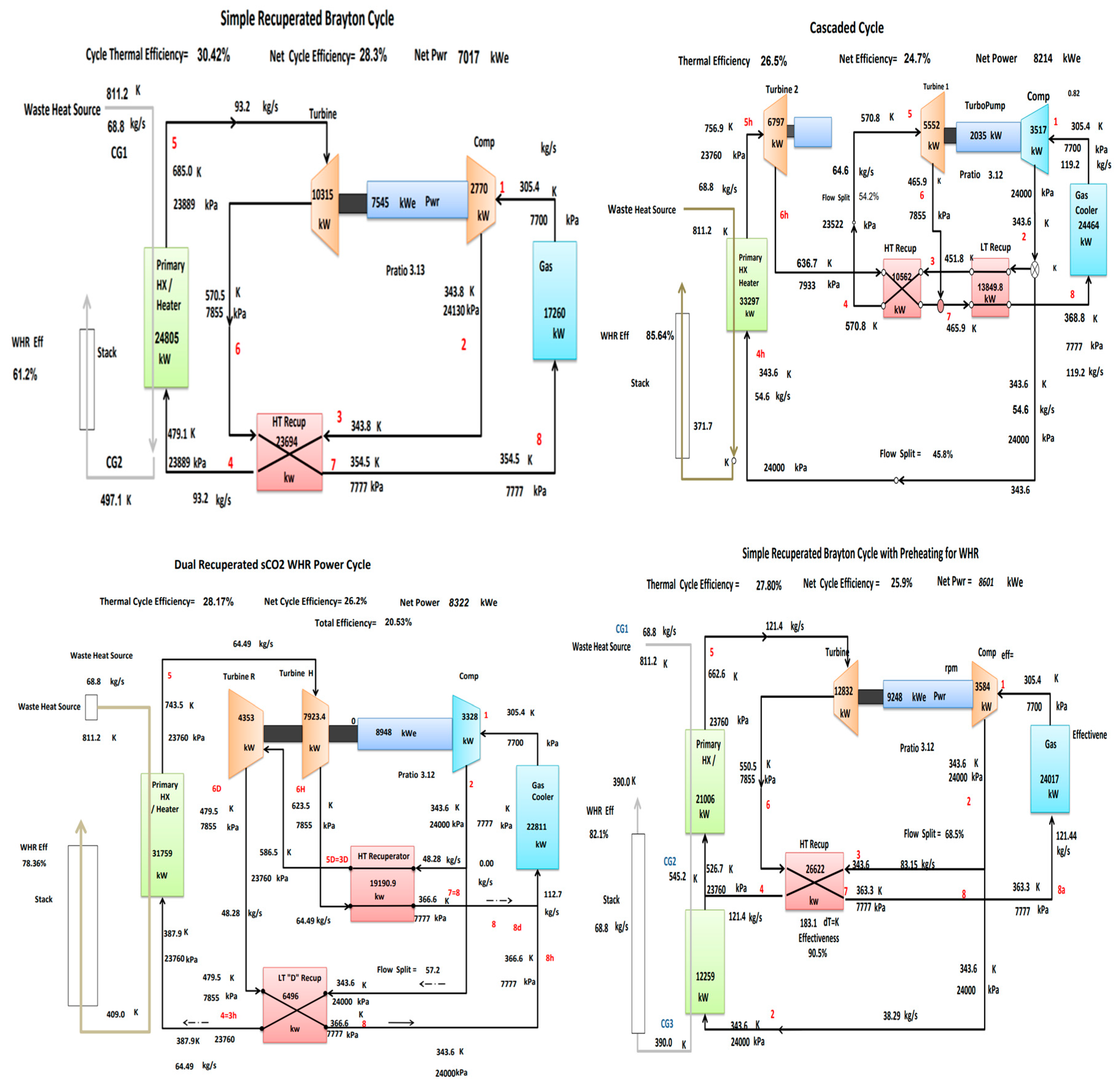
| Wright et al. [116] | 2016 | Gas turbine | Recuperation S-CO2 | 40,731 | 549 | 24 | 7.7 | 7017 | 30.42% | 61.20% |
| Cascaded S-CO2 cycle | 8214 | 26.50% | 85.64% | |||||||
| Dual recuperated sCO2 | 8322 | 28.17% | 78.36% | |||||||
| Recuperated Brayton cycle with preheating | 8601 | 27.80% | 82.10% | |||||||
| Manjunath et al. [120] | 2018 | Gas turbine | Recuperation S-CO2 with T-CO2 vapour compression cycle | 20,600 | 572 | 20 | >7.37 | 3138 | 38.70% | 44.50% |
| Song et al. [115] | 2018 | Engine waste heat | Preheating S-CO2 | 996 | 300 | 15 | 7.8 | 64 | - | - |
| Preheating S-CO2 with regeneration | 68 | |||||||||
| Zhang et al. [114] | 2020 | Internal combustion engines | Recompression S-CO2 | 235.8 | 519 | 25 | 8 | 33.06 | 35.86% | 58.70% |
| Manente et al. [117] | 2020 | Steel industry | S-CO2 dual expansion | 2010 | 600 | 20 | 7.63 | 1000 | 26.62% | 22.30% |
| Gas turbine | S-CO2 dual recuperation | 2312 | 28.40% | 19.39% | ||||||
| Fuel cell | S-CO2 partial heating | 2073 | 25.82% | 21.63% | ||||||
| Bonalumi et al. [121] | 2021 | Gas turbine | Partial heating S-CO2 | 4710 | 511 | 26 | 9.56 | 1550 | 25% | 70% |
| Sanchez et al. [122] | 2011 | Molten carbonate fuel cell | Simple recuperation S-CO2 | - | >650 | 22.5 | 7.5 | 583.6 | 39.90% | 59.40% |
| Marchionni et al. [123] | 2021 | Simulated waste heat source–Air heater | Simple recuperation S-CO2 | 830 | 650 | 20 | 7.4 | 84 | 23% | - |
| Reheating S-CO2 | 87 | 25% | - | |||||||
| Recompression S-CO2 | 85 | 24% | - | |||||||
| Recompression reheating S-CO2 | 88 | 27% | - | |||||||
| Preheating S-CO2 | 155 | 26% | - | |||||||
| Preheating Split-Expansion S-CO2 | 140 | 23% | - | |||||||
| Split-heating Split-Expansion S-CO2 | 110 | 17.50% | - | |||||||
| Preheating pre-compression S-CO2 | 150 | 25 | - |
Disclaimer/Publisher’s Note: The statements, opinions and data contained in all publications are solely those of the individual author(s) and contributor(s) and not of MDPI and/or the editor(s). MDPI and/or the editor(s) disclaim responsibility for any injury to people or property resulting from any ideas, methods, instructions or products referred to in the content. |
© 2023 by the authors. Licensee MDPI, Basel, Switzerland. This article is an open access article distributed under the terms and conditions of the Creative Commons Attribution (CC BY) license (https://creativecommons.org/licenses/by/4.0/).
Share and Cite
Zhang, X.; Ge, Y. Power Generation with Renewable Energy and Advanced Supercritical CO2 Thermodynamic Power Cycles: A Review. Energies 2023, 16, 7781. https://doi.org/10.3390/en16237781
Zhang X, Ge Y. Power Generation with Renewable Energy and Advanced Supercritical CO2 Thermodynamic Power Cycles: A Review. Energies. 2023; 16(23):7781. https://doi.org/10.3390/en16237781
Chicago/Turabian StyleZhang, Xinyu, and Yunting Ge. 2023. "Power Generation with Renewable Energy and Advanced Supercritical CO2 Thermodynamic Power Cycles: A Review" Energies 16, no. 23: 7781. https://doi.org/10.3390/en16237781