Article

Numerical Investigation of the Effects of the Hole Inclination Angle and Blowing Ratio on the Characteristics of Cooling and Stress in an Impingement/Effusion Cooling System

1
National Key Laboratory of Science and Technology on Aero Engines Aero-Thermodynamics, Beihang University, Beijing 102206, China
2
Research Institute of Aero-Engine, Beihang University, Beijing 102206, China
3
School of Energy and Power Engineering, Beihang University, Beijing 102206, China
4
AECC Sichuan Gas Turbine Establishment, Chengdu 610500, China
*
Author to whom correspondence should be addressed.
Energies 2023, 16(2), 937; https://doi.org/10.3390/en16020937
Submission received: 14 December 2022 / Revised: 5 January 2023 / Accepted: 11 January 2023 / Published: 13 January 2023
(This article belongs to the Special Issue Clean Combustion and Heat Transfer of Gas Turbine)

Abstract

:
Due to the uneven temperature field and temperature gradient introduced by an efficient cooling structure, the analysis of the stress field is necessary. In this study, the cooling characteristics and stress characteristics such as the thermal stress and thermomechanical stress of an impingement/effusion cooling system were investigated by employing a fluid–thermal-structure coupling simulation method. The effects of film hole injection angle (30°–90°) and blowing ratio (0.5–2.0) were studied. The results showed that the film hole shape and the non-uniform temperature field introduced by the cooling structure had a great influence on the stress field distribution. With the increase in the blowing ratio, not only the overall cooling effectiveness of the cooling system increased, but the maximum thermal stress and thermomechanical stress near film holes also increased. The cases with a smaller inclination angle could provide a better cooling performance, but caused a more serious stress concentration of the film hole. However, the thermal stress difference at the leading and trailing edges of the film hole increased with a decreasing inclination angle. The cases with a = 30° and 45° showed serious thermal stress concentration near the hole’s acute region.

1. Introduction

The inlet temperature of advanced aero-engines constantly increases to effectively increase the thrust. At present, the existing high-temperature-resistant materials cannot meet the growth rate of the turbine inlet temperature. It is necessary to use cooling technology to protect the turbine blade to ensure its safety and life [1].
In order to achieve efficient cooling, turbine blades usually apply a composite cooling system that combines internal and external cooling. Impingement/effusion cooling is a typical and promising composite cooling system that is widely employed for turbine blades [2]. Some researchers studied the influences of aerodynamic parameters on this cooling system, including the effect of the cold air mass flow rate [3], cross flow [4], and blowing ratio [5,6]. The blowing ratio (M) is an important parameter that affects the cooling performance of an impingement/effusion cooling system. The overall cooling effectiveness increases with an increase in the blowing ratio [5,6], while the adiabatic cooling effectiveness decreases gradually [6]. Since the cooling efficiency can be jointly affected by both internal impingement cooling and external effusion cooling, the influence of geometric parameters on the cooling performance is more complicated. The effects of the relative hole arrangements [7,8], hole numbers [9], hole diameter [10], hole pitch [11] of impingement and film holes, and inclination angle [12,13,14] of film holes has been studied previously. The inclination angle of film holes received more attention in previous studies because the film holes directly determine the gas outflow [12,13], and the cooling inside the film holes also plays an important role in the overall cooling effect [14].
Turbine blades operate in harsh working environments such as high temperatures and high rotation speeds. In addition to the effect of high temperatures on turbine blade life, stress is also one of the main failure mechanisms for turbine blades [15]. Turbine blade stress is mainly composed of centrifugal stress and thermal stress. The centrifugal stress is associated with the high-speed rotation of the turbine blade. The thermal stress is mainly caused by a non-uniform blade temperature field with a high temperature gradient. The stress distribution of the turbine blade becomes more complicated under the combined influences of centrifugal stress and thermal stress. The existence of cooling structures such as film holes destroys the geometric continuity of the turbine blades, which leads to the deterioration of the turbine blade’s stress distribution and seriously reduces the turbine blade’s lifetime. There have been many studies on test pieces with holes under tensile behavior to investigate the effect of the centrifugal load on cooling structures [16,17,18,19,20]. All results showed that the test piece with holes had an obvious stress concentration near the hole under a tensile state. Zhou et al. [18] and Zhang et al. [19] compared the effects of various hole inclination angles on cooling structures. They pointed out that the hole inclination angle can have a significant impact on the stress field distribution and the stress near the hole. Li et al. [20] conducted a study on a double-walled cooling structure and pointed out that the impingement hole distance can affect the maximum von Mises stress behavior.
The above studies that investigated the stress behavior of cooling structures at different temperatures and tensile loads provided important findings. These studies paid more attention to the material, creep, and damage behavior, but insufficient consideration was given to the non-uniform temperature effect on stress when the cooling structure performed the cooling function. Recently, a few studies were carried out on the thermal stress caused by the uneven temperature field and temperature gradient of a cooling structure [21,22,23,24,25,26]. Wang et al. [21], Jiang et al. [22], and Liu et al. [26] reported that the region of high thermal stress concentration occurred near the film hole. Wang et al. [21] also indicated that the maximum thermal stress could be reduced by changing the film hole angle. Skamniotis et al. [23,24,25] pointed out that it is important to consider the temperature-dependent thermoelastic properties of blade materials.
To summarize, extensive research has been carried out on impingement/effusion cooling systems. However, most of these studies focused on the cooling performance and heat transfer. The inhomogeneous temperature field and cooling structure parameters have a great influence on thermal stress and thermomechanical stress distributions, which will further affect the lifetime of a turbine blade [15]. Although there has been limited research on the stress characteristics of cooling systems that considered the temperature distribution, very few studies on the stress characteristics of impingement/effusion cooling systems are available in the open literature. In addition, the recent studies [23,24,25,26] all showed that the film hole stress is one of the most important issues in the design of a cooling system. The film hole plays an important role in the cooling performance of such cooling systems. However, the existence of film holes can destroy the geometric continuity of turbine blades and deteriorate the stress distribution of turbine blades. Therefore, it is necessary to study the effect of the inclination angle of film holes on impingement/effusion cooling systems.
In this paper, the cooling characteristics and stress characteristics of an impingement/effusion cooling system with different film hole inclination angles (α) using different blowing ratios (M) were comprehensively investigated based on a fluid–thermal-structure coupling simulation method. The value of α was varied from 30° to 90°, and M was set from 0.5 to 2.0. The objective was to discuss the influence of different geometric (α) and aerodynamic (M) parameters on the overall cooling performance and the effect of the resulting inhomogeneous temperature field on the thermal stress distribution. Finally, the performance of thermomechanical stress under a 200 MPa centrifugal load was discussed.

2. Numerical Setup

2.1. Research Model

The research model studied in this paper is shown in Figure 1a.
For the fluid domain, the coolant in the cooling cavity impinged onto the internal surface of film plate after passing through the impingement holes and formed a protective film when it was discharged through the film holes. The high-temperature mainstream flowed in from the upstream of film plate. Figure 1b shows the dimensions of model, and Figure 1c presents the staggered hole arrangement for the impingement and film holes (the streamwise position of each impingement hole was in the middle of the two film hole inlets). The diameter (D) of each of the two holes was 0.4 mm, which is a typical size of a turbine blade. The hole pitches of the spanwise distance and streamwise distance were 5D and 10D, respectively. Four angles of 30°, 45°, 60°, and 90° for the film holes were investigated in this study. The angle of the impingement holes was 90°. The thickness of both the film plate and the impingement plate and the impingement distance were all 2.5D. The front and back of the mainstream were respectively delayed by 25D to eliminate the inlet and outlet effects. Other structural dimensions are listed in Figure 1.

2.2. Numerical Method

The temperature field and stress field of the cooling system were obtained in this study by employing the fluid–thermal-structure coupling simulation method. First, the temperature field of the fluid and solid domains and flow field were calculated by using computational fluid dynamics (CFD) based on a conjugate heat transfer analysis. Then, the temperature field of the predicted solid domain was used as the temperature load, and the thermal stress and thermomechanical stress of the cooling system were calculated by using the finite element method (FEM). The effects of the structural deformation on the flow and heat transfer were not considered in this study because the deformation of the turbine blade was relatively small [27]. The calculations of these two parts are described below.

2.2.1. Conjugate Heat Transfer Analysis

The boundary conditions of the computation domain are shown Figure 1a. The temperature of the mainstream and coolant were set at 1500 K and 750 K, respectively, to meet the density ratio under real engine operating conditions [28,29]. The mainstream Reynolds number (Re) based on D was set at 3326, from which the mainstream mass flow rate was determined. The mass flow rate of the coolant depended on the blowing ratio (M). Four consecutive values of M (0.5, 1.0, 1.5, and 2.0) were investigated in this study. The turbulence intensity of the mainstream and coolant were both medium (intensity = 5%). A static pressure of 1,013,250 Pa was specified at the outlet. Detailed boundary conditions are shown in Table 1. Both spanwise sides of the fluid and solid surfaces were set as periodic boundary conditions because the computation domain was a period. The solid domain only considered the film plate for conjugate calculation with the fluid domain. Since there was almost no heat conduction, the impingement plate was not included. The interfaces between the fluid domain and film plate were set as a conjugate boundary to transfer the heat flux. The other walls were set as adiabatic walls. Dry air was used as the fluid material. The material of the film plate was the superalloy GH3536. The physical properties of the air and GH3536, such as the specific heat capacity, density, and thermal conductivity, depended on the temperature and were obtained by fitting values at different temperatures. The viscosity coefficient of the air was set using Sutherland’s formula. The mainstream Re mentioned above is defined in in Equation (1), and M is shown in Equation (2):
R e = ρ g u g D μ
M = ρ c u c ρ g u g
where ρg and ug represent the density and velocity of the mainstream, respectively; μ is the viscosity coefficient of the mainstream; ρc represents the coolant density; and ug is the coolant velocity at the film cooling hole.
The overall cooling effectiveness can represent the combined internal and cooling capacity of an impingement/effusion cooling system, which is defined in Equation (3). The Nusselt number (Nu) shown in Equation (4) can represent the heat transfer on the internal surface:
ϕ = T g T w T g T c
N u = h D k
where Tg and Tc represent the temperature of mainstream and coolant, respectively; Tw is the external surface temperature of film plate; k represents the fluid thermal conductivity; and h is the heat transfer coefficient and can be calculated as h = q w , in / ( T w , in T c ) , where qw,in and Tw,in represent the heat flux and temperature of internal surface of film plate, respectively.
The ANSYS CFX was applied for steady-state numerical computations. The SST k-ω turbulence model was selected due to its better simulation results for impingement/effusion cooling systems [5,14,30]. High-resolution discretization schemes for the convection and turbulence terms were employed to obtain the more accurate simulation results. Turbulence model validation was conducted in our previous study [31]; the validation process is briefly described here. The experimental model of impingement/effusion cooling in [30] was used for the numerical simulation due to the similar geometry parameters to those of the model in this study. Six widely used turbulence models—SST k-ω, k-ω, k-ε, RNG k-ε, BLS, and SSG—were selected for calculation, and their reliabilities in predicting flow and heat transfer were evaluated by comparing the results with the experimental data in [30]. A comparison of the laterally averaged overall cooling effectiveness ( ϕ ) is shown in Figure 2a. The results showed that the cooling effectiveness trend of the SST k-ω model was the most similar to that of the experiment. The effectiveness of all models was underestimated at X/D > 20, but the values of the SST k-ω model were the closest to those of the experimental results. Therefore, the SST k-ω turbulence model was adopted in this paper. In addition, the mainstream Reynolds number, blowing ratio, and temperature ratio in the literature’s experimental research [30] were similar to those used in this study, and the inclination angle of the film hole was also 30 degrees. A comparison of the globally averaged ϕ between the present simulation’s results with α = 30° in this study and the experimental values from the literature was conducted; the results are shown in Figure 2b. The numerical results of this study were in good agreement with the trend in the literature data. Since the film holes in the literature were in a staggered arrangement, the present study used a linear arrangement, and there were deviations of no more than 10% in the large blowing ratio, which was reasonably acceptable. The average temperature of the external surface of the film plate was monitored to judge the calculation convergence. The simulation results were considered reasonably well converged when the temperature variation remained stable for at least 500 iterations and the RMS residuals were less than 10−5.
Figure 3 shows the mesh obtained by using the software Fluent Meshing. The purple represents the mesh of the fluid domain and brown represents the mesh of the solid domain. There were 15 prism layers; these are pointed out with red arrows in Figure 3. The y+ of the first-layer grid was less than 1 to fulfill the demand of the turbulence mode. The grid independence validation was carried out by comparing three different sizes of grid 1 to grid 3. For case with a = 30°, the numbers of grids from grid 1 to grid 3 were 7.1 million, 14.9 million, and 25.1 million, respectively. The lateral ϕ was used to evaluate the independence of the grids as shown in Figure 4. The cooling effectiveness of grid 2 and grid 3 was almost the same. Therefore, the grid parameters settings of grid 2 were used for the conjugate simulation.

2.2.2. Stress Analysis

The commercial software ANSYS Workbench was used to solve the stress of the cooling system. The temperature distributions at different values of M obtained by the CFD simulation were transferred to the commercial software ANSYS Workbench and re-interpolated to obtain the temperature field that could be used by the finite element. The fundamental equations of the linear structural problem [32] are shown in Equations (5)–(7):
T σ + f = 0
ε = s
σ = D ε + ε th
where σ and f are the stress and body force, respectively; ε and ε th represent the stain and thermal strain, respectively; s is the displacement; and D is the elastic stiffness matrix.
The von Mises stress, also known as the equivalent stress, was used as the criterion, which could be calculated using Equation (8):
σ VM = σ x + σ y 2 + σ y + σ z 2 + σ x + σ z 2 / 2 1 / 2
where σ VM represents the equivalent stress; and σ x , σ y , and σ z are the stress in the X, Y, and Z direction, respectively.
Since the two walls of the film plate were in contact with the high-temperature mainstream and coolant, the temperature field was severely uneven. In addition, the change in the inclination angle of the film hole also changed the structure of the cooling system. All of these could affect the stress distribution of the film plate. Therefore, only the stress behaviors of the film plate were the focus of this paper. Two types of stress characteristics—thermal stress and thermomechanical stress—were investigated in this study. The thermal stress was mainly caused by the non-uniform temperature field of the cooling system and the film holes. The thermomechanical stress was the total stress under the joint action of the inhomogeneous temperature field and centrifugal load. Thus, two boundary conditions were set to obtain the thermal stress distribution and thermomechanical stress distribution. The constraints for thermal stress are shown in Figure 5a: the Y and Z directions of Point A were fixed, and the Y direction of point B was fixed. The other directions of these two points were free. The X direction of surface C was fixed, and the Y and Z directions were free. In this way, the film plate could expand freely without translation and rotation, and the thermal stress could depend on the inhomogeneous temperature field and the film holes. The constraints of thermomechanical stress are shown in Figure 5b: the uniform pressure load of 200 MPa was applied in the direction perpendicular to mainstream to simulate the centrifugal stress effect. It should be noted that the thermal stress and thermomechanical stress presented in this paper were all von Mises stress.
The finite element mesh is generated by the commercial software ANSYS Meshing. The mesh around the film holes was densified to obtain greater stress detail changes and more accurate calculations. When the calculated stress had less than a 0.5% difference compared with that of the finer mesh, the mesh was considered suitable for analysis.

3. Results and Discussion

3.1. Cooling Characteristics

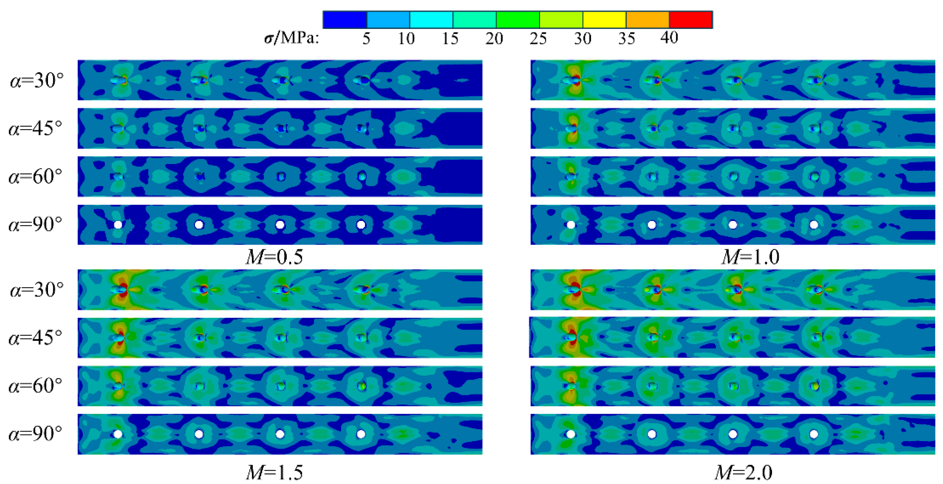
Figure 6 shows the contours of the overall cooling effectiveness ( ϕ ) for all inclination angled hole cases at each blowing ratio (M). The region near the film cooling holes showed higher cooling efficiency under different values of M due to the coolant passing through the holes, which had a cooling effect around the film holes. For all angled hole cases, the film could cover the surface of the film plate well at M = 0.5. As M was increased, the traces of film coverage gradually weakened. The reason was that the increasing M could enhance the momentum of the coolant. This could promote the occurrence of the film lift-off phenomenon and reduce the film-cooling effect. However, the cooling performance of the cooling system increased with an increasing M. This phenomenon was consistent with the results obtained by Oh [18]. The reason should be attributed to the continuous enhancement of the internal impingement holes’ cooling effect.
In addition to the areas near and downstream of the film holes, there were also some areas with high cooling efficiency in the direction of Y/D = ±2.5 at the relative position of the impingement holes. The cooling efficiency of these areas showed a gradually increasing trend with an increasing M. This was due to the effect of the internal jet impingement. The position of the impingement holes caused these areas to be more affected by the impingement cooling. The influence of the internal impingement on the heat transfer will be explained later.
Figure 6 also indicates that the cooling system with small-inclination angled holes could always provide a relatively higher cooling efficiency under each M. When M = 0.5, the film coverage region of the cooling system with an inclination angle of 30° was the largest. As M was increased, although the covering effect of the film was weakened, the smaller inclination angles of the holes still provided a better cooling performance. This was because the smaller inclination angle of the film holes caused the film to attach to the plate’s surface more easily.
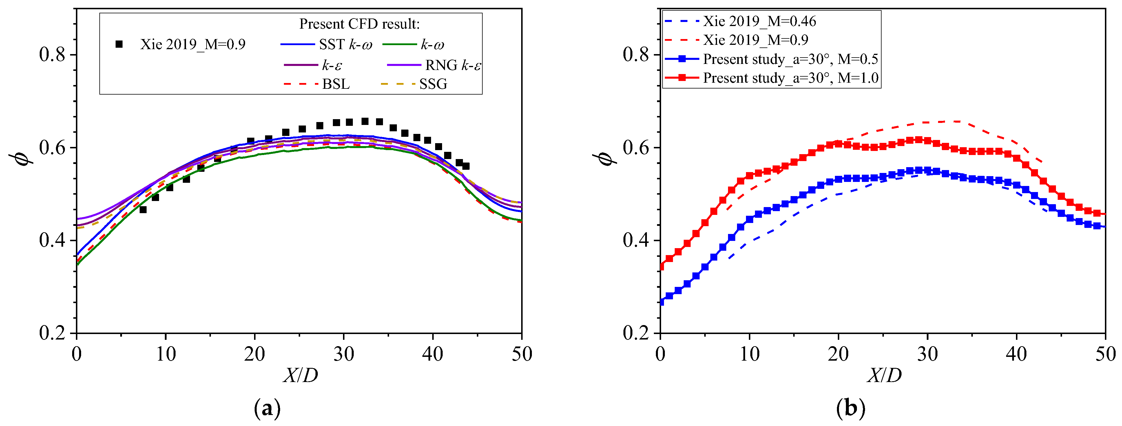
Figure 7 shows the laterally averaged ϕ corresponding to the cases shown in Figure 6. The ϕ of the cooling system with smaller-inclination angled holes was higher under each M. When M = 0.5, the ϕ of the cases with holes with different inclination angles showed the large difference level. As M was increased gradually, the gap of cooling effectiveness between cooling systems with different hole-inclination angles gradually decreased, especially at the end of the flow. This was because the film cooling played a major role under the condition of a small M, and the effect of the impingement cooling increased and gradually assumed the dominant role as M was increased.
Figure 8 shows the contours of the non-dimensional temperature θ at the Y = 0 plane for both the fluid and solid domains. θ is defined as: θ = ( T g T ) / ( T g T c ) , where T is the temperature at one point. Under the M = 0.5 condition, the jet flowing out of the film holes with α = 30° was easier to attach to the wall. Although the jet stream with α = 30° shot out perpendicular to the main flow direction, it could still adhere to the wall. The thickness of the film layer with α showed an obvious difference, and the smaller α could provide a thinner film. As M was increased to 1.0, the film jet with α = 30° had a tendency to detach from the wall surface after outflow. The case with α = 90° had a relatively high temperature downstream of the film hole that was caused by the main flow introduced by the entrainment effect. Since the film hole was perpendicular to the main flow, the entrainment effect on the vortex formed by the film jet could promote the hot gas to directly contact the wall. As M was increased to 2.0, film jets with different values of α were all detached from the wall. The entrainment effect began to occur downstream from the film hole for the case with α = 30°. However, the mainstream introduced by the entrainment was very close to the film hole outlet for the case with α = 90°, and the film could no longer work normally on the outer surface. The entrainment phenomenon could further influence the temperature distribution of the solid domain. It can be seen in the above that the smaller inclination angle of the film hole could provide effective film protection. The difference in the film cooling effect between a small α and a larger α was larger with an increasing M.
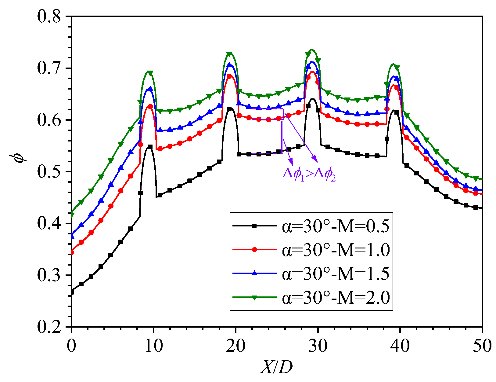
In order to further discuss the conjugate effect of film cooling and impingement cooling in the impingement/effusion cooling system, the laterally averaged ϕ with α = 30° under different values of M is presented in Figure 9. The contours of the local Nu of the internal surface of the film plate is shown in Figure 10. Figure 9 indicates that the laterally averaged ϕ gradually increased with an increasing M. In addition, it can be observed that the increase in effectiveness Δ ϕ 2 when M was increased from 1.0 to 1.5 was much lower than that of Δ ϕ 1 when M was increased from 0.5 to 1.0. Liu [6] reported that the adiabatic cooling effectiveness decreased with an increasing M in the range of 0.5 to 2.0 for an impingement/effusion cooling system. The research model was similar to the one used in this paper. Thus, the increase in ϕ was attributed to the heat transfer enhancement of the internal impingement cooling. When combined with those in Figure 10 the results showed that the local Nu of the corresponding position of the impingement hole increased significantly when M was increased from 0.5 to 1.0. This showed that the heat transfer of the inner surface was significantly enhanced, which could further promote the improvement in the cooling performance. The coolant jet impinged on the inner surface and formed the stagnant region, and the heat exchange in these regions could be greatly enhanced. It is worth noting that there were higher heat transfer zones between the lower heat transfer zones. There were collisions and strong disturbances between adjacent wall flows. As M was increased, the velocity of the impinging jet and wall jet increased, which led to a significant increase in the heat transfer enhancement. In addition, another reason for the phenomenon that Δ ϕ 1 was higher than Δ ϕ 2 was that the constriction effect and local flow detachment occurred at part of the perimeter of the film hole inlet for the inclined film hole, especially the 30° film hole. The fluid impinged on the inlet’s leading edge and created a low-velocity recirculation region at the trailing edge of the film holes. At M = 0.5, the contraction effect was very strong. As M was increased, this effect gradually weakened.
Figure 11 shows the contours of θ at the Y = 0 plane for the film plate. Under the same value of M, the non-dimensional temperature around the film hole increased with a decreasing α. The reason was that the heat-exchange area in the film hole increased as α decreases, which was beneficial to the cooling near film cooling hole. This can also be seen in the θ of the jet in the film holes shown in Figure 8. The black dimensionless line of temperature could qualitatively represent the change degree of the temperature gradient. As M was increased, the dimensionless temperature lines of the solid under the same α become denser, which indicated that the temperature gradient along the Z direction increased gradually. In addition, the dimensionless temperature curves near the film holes for cases with different α were obviously different. This meant that the cooling in the film hole also affected the distribution trend of the film plate’s temperature. Therefore, the cooling in the film hole was also an important component of the cooling.
Figure 12 presents the relative heat transfer quantity (Qi/Q0) on the internal surface of the film holes for all inclinations of the angled hole cases at each M. Q0 is the heat transfer quantity on the internal surface for the case with α = 90° at M = 0.5, with which that of the other cases was compared. The heat transfer in the film holes for cases with α = 90° showed the lowest level at each blowing ratio. As α was decreased, the heat transfer on the internal surface of film holes increased gradually. The heat transfer quantity of the film hole surface for the case with α = 30° was about 3.0 times that of the case with α = 90° under the condition of M = 0.5. The significantly enhanced heat transfer was attributed to the increased heat transfer area on the inner surface of the film holes; the heat transfer area of the internal surface of the film holes at α = 30° was about twice that at α = 90°. This further improved the cooling effect at a small α. As M was increased, the heat transfer at the same α also increased significantly. This was due to the significant increase in the velocity of the jet entering the film hole, which enhanced the heat transfer level in the holes.
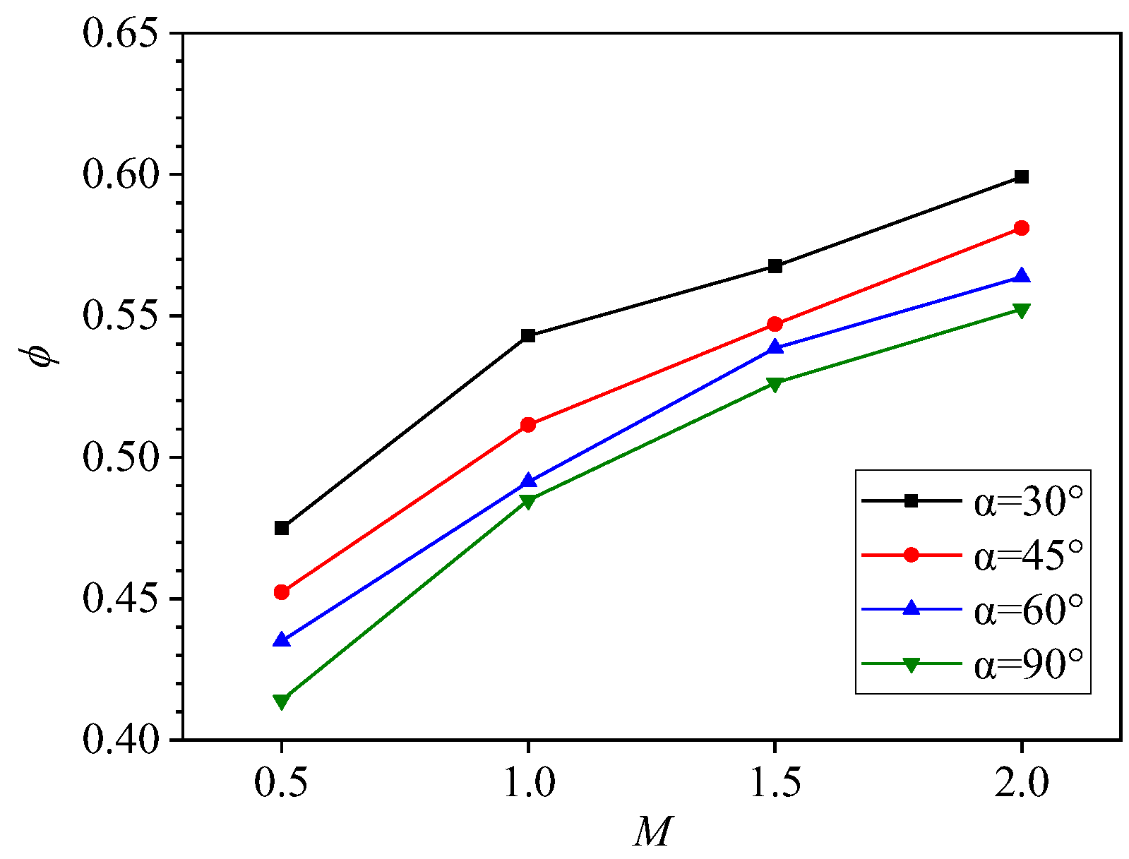
The area-averaged ϕ is presented in Figure 13. The results showed that the cooling system with α = 30° provided the highest area-averaged ϕ at all values of M. The area-averaged ϕ for cases with different inclination angles also increased with an increasing M.

3.2. Thermal Stress Distribution

Since the film cooling plate was directly in contact with the high-temperature gas, the uneven distribution of the temperature field was more serious than that of the impingement cooling plate, so this study focused on the stress distribution of the film cooling plate. Figure 14 shows the contours of thermal stress distribution on the external wall of the film plate. The areas of high thermal stress were concentrated around the film holes. This was because the generation of thermal stress was mainly caused by the uneven temperature distribution of the solid domain due to the setting of boundary conditions. The inhomogeneous temperature distribution could generate temperature gradients. This led to different levels of expansion and displacement in different regions that could not expand freely under mutual constraints and caused greater stress. The regions around the film holes were the high-cooling-efficiency areas, which was represented by the large temperature gradient around the film holes. Another reason was that the stress concentration easily occurred around the holes. Furthermore, due to the influence of the impingement cooling, the position corresponding to the impingement hole also caused a large temperature gradient, and the region of high thermal stress was also generated in these areas. The high-thermal-stress area of these areas gradually increased with an increasing M, which could further affect the thermal stress near the holes. As mentioned above, the heat transfer enhancement of the internal wall was improved with an increasing M. This could affect the whole temperature distribution of the film plate and made the stress concentration more obvious. When M ≤ 1.0, it was found that a large thermal stress was also generated at the connection line of the film holes. This may have been due to the higher film coverage at a smaller M, thereby resulting in a greater degree of unevenness in the temperature gradient near the film hole line and an increase in the thermal stress there. Under the same M, the case with smaller α showed a greater number of high-thermal-stress regions, which was in agreement with Wang’s findings [21]. This may have been due to the heat transfer in the film holes. The smaller inclination angle had a greater effect on the temperature distribution in the solid domain due to the larger heat transfer area, which increased the inhomogeneity of the temperature field.
Cracks in turbine blades often occur around the film holes, so it was necessary to analyze the thermal stress distribution around the film holes. In order to avoid the influence of the inlet and outlet boundary conditions, a third film hole in the flow direction was selected for analysis, hereinafter referred to as the research film hole. Figure 15 shows the thermal stress trend of the hole’s exit presented in the form of the polar coordinate diagram in order to more vividly display the stress distribution. The angle β represents the angle between the hole’s leading edge (LE) and the current position, 0 degrees represents the location of hole’s LE, and 180 degrees represents the location of hole’s trailing edge (TE). The results showed that cases with a different α had different thermal stress distributions near the hole. As α was decreased, the difference in the thermal stress distribution between the hole’s LE and trailing edge increased gradually. Under different values of M, the maximum thermal stress for cases with α = 30° and α = 45° was concentrated at the hole’s LE and on both sides of the LE. However, the thermal stress of these regions for cases with α = 60° and α = 90° showed a more complicated trend. When M ≤ 1.0, the stress concentration near the hole’s trailing edge was more obvious; when M ≥ 1.5, the maximum thermal stress occurred near the hole’s LE. The reasons for these phenomena may have been the complex effect of the cooling structure geometry and the temperature field distribution. Compared with a vertical film hole (α = 90°), the curvature of leading and trailing edge for a skewed film hole was larger, which made it prone to generate a greater stress concentration. In addition, for cases with α = 30° and α = 45°, the hole’s LE was acute and has fewer constraints. Thus, the maximum thermal stress was more likely to occur there [18]. For cases with α = 60° and α = 90°, the constraints on the leading and trailing edge were not much different, especially for the α = 90° case. At this time, the distribution of the thermal stress may have been mainly affected by the temperature field and temperature gradient. When combining Figure 7 and Figure 12, it can be hypothesized that when M is small (M ≤ 1.0), the film coverage effect made the temperature gradient near the hole’s trailing edges more severe compared to near the LE region. When M was increased to 1.5, the main flow was in direct contact with the wall due to the entrainment effect and the temperature gradient near the hole LE is more serious, which could have resulted in a greater stress concentration near the LE region.
The contours of thermal stress distribution at the internal wall of the film plate are shown in Figure 16. Similar to the thermal stress distribution on the external surface, the region of high thermal stress concentration was generated near the film hole and the corresponding position of impingement hole. Since the impinging jet directly acted on the internal surface, the increase in the high thermal stress region on the internal surface was more obvious than that on the external surface with an increasing M and heat transfer. The thermal stress concentration occurred at both sides near the hole’s trailing edge for cases with α = 30° and α = 45°. In addition, a separate area of high thermal stress was also observed in the region connecting the holes except for α = 30°. This can be explained by the phenomenon of a high heat transfer band between the two film holes shown in Figure 11 The heat transfer in these areas was strong and the temperature gradient was large; this is shown by the convex dimensionless temperature line in the Z direction that corresponds to the position of the heat transfer belt in Figure 11 However, due to the increased heat transfer area and longer heat transfer path, the cooling effect in the film hole with α = 30° had a greater influence on the temperature distribution around the hole, and no convex dimensionless temperature line was observed.
Figure 17 shows the thermal stress distribution trend for the hole inlet near the research film hole. Unlike the film hole’s exit, the acute region was at the hole’s tailing edge. For cases with skewed film holes, the thermal stress distribution with the same α showed a similar variation trend under different values of M. As M was increased, the thermal stress values near the hole for different values of α increased significantly. The cases with α = 30° showed the highest thermal stress values under different values of M near the hole’s trailing edge. As α was increased, the high thermal stress value gradually shifted to the area away from the hole’s trailing edge. Similarly, the stress distribution trends for cases with α = 90° were relatively irregular and mainly affected by the temperature gradient.
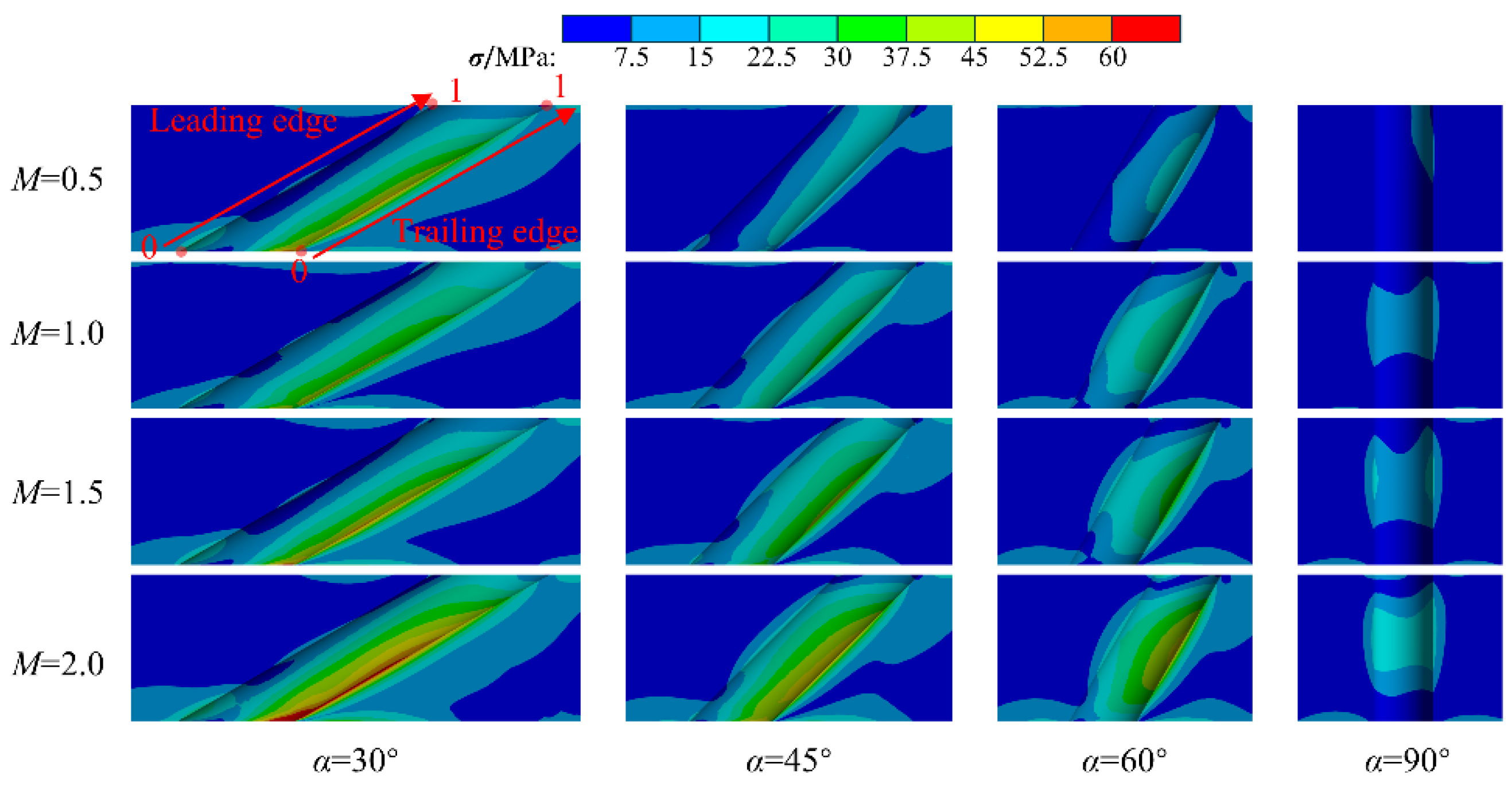
The contours of thermal stress at the Y= 0 plane of the research film hole is presented in Figure 18 to show the stress distribution in and around the hole. Figure 19 shows the thermal stress distribution on the path of the LE and TE of the film hole, where position 0 is at the hole inlet and position 1 is at the hole outlet. Figure 18 indicates that the high-thermal-stress region around the film hole gradually increased with a decreasing α. Compared with cases with other values of α, the α = 30° cases showed an obvious stress concentration near the inlet LE region of the film hole. As M was increased, the stress concentration there became more obvious. The thermal stress distribution of the LE and TE region for cases with α = 30° had the largest difference (see Figure 19). However, the vertical hole was relatively consistent. This meant that the decrease in α would increase the difference level of the thermal stress distribution near the LE and TE. In addition, as α was increased, the stress concentration gradually moved toward the middle region of hole path.
Figure 20 shows the temperature difference (∆T) of the maximum and minimum temperature and the maximum stress value of the film hole under different values of M and α. ∆T could qualitatively represent the temperature gradient level of the film hole. As M was increased, the temperature difference of cases with a fixed α gradually increased, which indicated that the whole temperature gradient of the film hole was gradually increasing. At the same time, the maximum thermal stress value of the film hole also increased. This further illustrated that the thermal stress of the film hole was proportional to the temperature difference; that is, the temperature gradient increase could increase the thermal stress level of the film hole. In addition, the maximum stress value of the film hole increased gradually with a decreasing α under the same M.

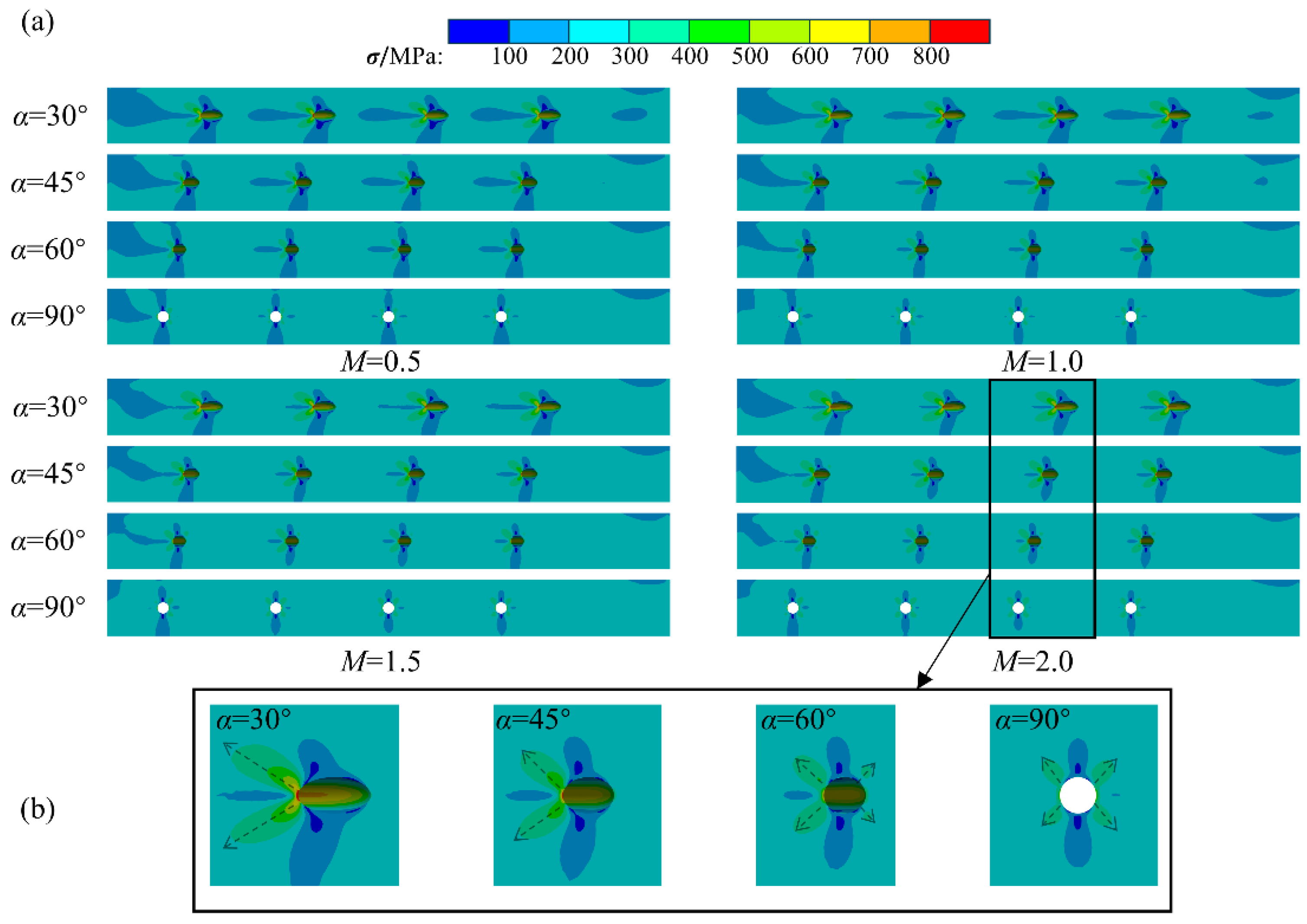
3.3. Thermomechanical Stress Distribution

Figure 21a shows the contours of thermomechanical stress distribution at the external surface of the film plate under a 200 MPa centrifugal load and thermal stress, and Figure 21b shows the thermomechanical stress distribution near the film hole at M = 2.0. Figure 22 presents the thermomechanical stress trend of the inlet and outlet near the research film hole. It can be observed in Figure 21a and Figure 22 that for cases with the same α, the thermomechanical stress distribution trend near the film holes was essentially the same under different values of M, and only the high-stress region and the maximum stress value changed. This indicated that under the centrifugal load of 200 MPa, the different temperature fields caused by the different values of M had little effect on the thermomechanical stress distribution. The dotted line in Figure 21b shows the path of the stress gradient in the high-stress region near the film hole. There was an obvious stress concentration phenomenon around the hole’s LE for the case with α = 30°. The stress contour band presents a semi-butterfly-like shape and shows the maximum stress near the hole leading edge. The wing part of the semi-butterfly band had a high-stress region with a higher stress level than the overall stress level of the film plate, and the high-stress gradient appeared when it was far away from the film hole. When combined with Figure 22a,b, it can be seen that stress concentration also occurred at the LE region of the film hole’s outlet, but it was smaller than that at the leading edge. As α was increased to 45° and 60°, the stress concentration near the hole’s LE was still obvious, and the semi-butterfly-like band decreased. However, the wing part of the semi-butterfly; that is, the angle between the gradient direction and the horizontal line in the high-stress area, gradually increased. The difference between the high-thermal-stress regions of the hole’s LE and TE gradually decreased. When α was increased to 90°, the stress distribution near the film hole showed a typical butterfly-like distribution, and high-stress regions and low-stress regions appeared alternately along the film hole. Figure 22 also shows that the change in α had a significant effect on the thermomechanical stress distribution around the film hole. At the same M, the acute side of the film hole presented the highest level of stress as α was decreased. This indicated that cooling systems with small inclination angles are more prone to damage and have shorter lifetimes under the joint actions of thermal stress and centrifugal load.
Compared with the thermal stress distribution on the film plate and near the film hole mentioned above, the 200 MPa centrifugal load obviously changed the distribution form of the overall stress field. Under different values of M, the thermal stress distribution of cases with different inclination angles was greatly affected by the temperature field and temperature gradient. However, the thermomechanical stress near the film hole was relatively regular at different values of M for each inclination angle, and the stress concentration mainly occurred in the area where the hole curvature was large. According to previous studies, stress concentration mainly occurs in the direction perpendicular to the loading direction [33]. In this study, the loading direction of the centrifugal load was in the vertical direction of the mainstream, which easily caused stress concentration near the hole’s LE and TE. For the skewed film holes, there were fewer constraints at the acute region, so the stress concentration was more evident under the effect of the centrifugal load.
Figure 23 shows the contours of thermomechanical stress at the Y = 0 plane of the research film hole. For cases with α = 30°, the stress concentration appeared at the TE region of the hole’s entrance and the LE region of the hole’s exit. As M was increased to 45° and 60°, the region with the largest stress concentration was still at the acute area of film hole, but the maximum stress value decreased. As α was increased to 90°, the stress concentration on both sides of the hole’s LE and TE region was the smallest and the distribution was more uniform. The coverage area of the high-stress region near the hole’s leading edge gradually increased with an increasing M, especially in the case with a small α.
Figure 24 shows the thermomechanical stress distribution on the LE and TE paths of the research film hole under M = 0.5 and 2.0. For cases with skewed film holes, the stress gradually increased at the LE and decreased at the TE from the hole’s entrance to the hole’s exit. For cases with skewed film holes, the stress along the LE path increased gradually at L/Ltotal < 0.25, increased slowly at 0.25 < L/Ltotal < 0.75, and then increased rapidly at L/Ltotal > 0.75. The stress trend along the TE path was just the opposite. Moreover, due to the different constraints at the hole’s leading and trailing edges, the maximum stress value for the acute region gradually increased and the maximum stress value for the obtuse region gradually decreased as the α was decreased. The difference in the stress distribution between the hole’s LE and TE paths for the α = 90° case was the smallest, and the stress level changed slightly from film hole’s inlet to outlet Therefore, for the skewed film holes, the damage occurred more easily at their acute regions, which also reflected that the change in the geometric parameters of the film holes had an obvious impact on the hole damage.
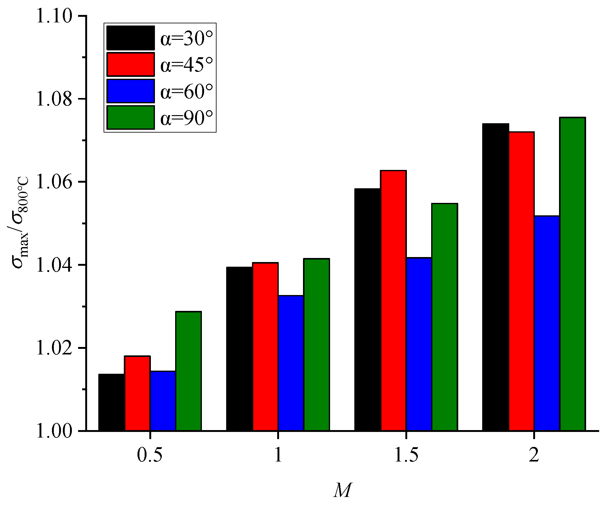
A cooling system will produce an uneven temperature field when it protects the blade. The case under a uniform temperature field of 800 °C was studied with the same centrifugal force to further study the influence of the temperature gradient brought about by cooling on the thermomechanical stress. Figure 25 presents the ratios of the maximum thermomechanical stress at different values of M to the stress under the temperature of 800 °C for the research film hole. The results showed that the maximum stress of the film hole under different values of M was higher than that under the uniform temperature field of 800 °C, which indicated that the combined effect of thermal stress and centrifugal load introduced by the inhomogeneous temperature field caused the maximum stress value to be larger than that under the uniform temperature field. The value of the maximum thermomechanical stress of the film hole at each value of α increased with an increasing M, which was attributed to the increases in the temperature gradient and thermal stress near the hole.

4. Conclusions

This study conducted a fluid–thermal-structure coupling analysis of an impingement/effusion cooling system. The novelty of the current paper in comparison with the previous works is that the cooling characteristics and stress characteristics of the impingement/effusion cooling system were simultaneously studied to evaluate the cooling system’s performance more comprehensively. A conjugate heat transfer analysis was performed to obtain the temperature field and cooling characteristics, and then the thermal stress and thermomechanical stress under a centrifugal load of 200 MPa were evaluated by using a finite element analysis based on the calculated temperature field. The effects of the blowing ratios (0.5–2.0) and film hole inclination angles (30°–90°) were considered. The main conclusions were as follows:
(1)
As M increases, the overall cooling effectiveness of the impingement/effusion cooling system at different inclination angles increases continuously. This is the result of the combined effects of film cooling and impingement cooling.
(2)
A smaller inclination angle of the film hole can provide a larger coverage of film, and it can increase the heat exchange area in the film hole and improve the overall cooling performance of the cooling system.
(3)
Stress concentration tends to occur around the film hole. An increase in M can increase the temperature gradient around the film hole and further increase the overall thermal stress level of the cooling system. The decrease in the hole inclination angle can cause a stress distribution difference near the LE and TE regions of the film hole to become more obvious, and the stress concentration phenomenon near the hole’s acute region will be more serious.
(4)
The addition of centrifugal stress will change the overall stress distribution. The thermomechanical stress for cases with different values of α showed a similar trend, but the maximum stress value gradually increased with the increasing M. As α was decreased, the stress concentration gradually presented a semi-butterfly distribution. Cases with α = 30° showed the highest thermomechanical stress level and the largest degree of stress concentration.
Temperature and stress are the main factors that affect the creep lifetime of turbine blades. Based on the above research, we know that the overall cooling effectiveness of an impingement/effusion cooling system will continuously increase with an increasing M and a decreasing α. In traditional cooling system designs, temperature-related design indicators (such as the overall cooling effectiveness in this study) are paid greater attention. This means that a smaller α and a higher M can achieve a better cooling performance and are conducive to the effective operation of the cooling system. However, this study showed that the levels of thermal stress and thermomechanical stress also increased accordingly with an increasing M and a decreasing α, which was detrimental to cooling system. Therefore, when designing a cooling structure, the designer should not only pay attention to the cooling performance, but also should consider the stress change caused by the temperature field of the cooling system. The results of this study provide fundamental information on the cooling and stress characteristics required for the design of such cooling systems. In the design of the cooling structures of turbine blades, the influence of the blowing ratio and the inclination angle of the film holes can be considered comprehensively to ensure that the cooling efficiency meets the requirements and at the same time reduce the blade stress as much as possible to improve turbine blade life.

Author Contributions

Conceptualization, H.L. and R.Y.; Data curation, R.Y.; Formal analysis, D.Z.; Investigation, D.Z.; Project administration, H.L.; Supervision, H.L.; Validation, Y.Z.; Visualization, D.Z. and S.L.; Writing—original draft, D.Z.; Writing—review and editing, R.Y. All authors have read and agreed to the published version of the manuscript.

Funding

This work was supported by the National Natural Science Foundation of China (grant number 52225602), the National Science and Technology Major Project (grant number 2019-III-0008-0051), and the Defense Industrial Technology Development Program (grant number JCKY2021601B206). The funding sources were not involved in the study design; in the collection, analysis, or interpretation of data; in the writing of the report; or in the decision to submit the article for publication.

Data Availability Statement

Not applicable.

Conflicts of Interest

The authors declare no conflict of interest.

References

  1. Unnikrishnan, U.; Yang, V. A review of cooling technologies for high temperature rotating components in gas turbine. Propuls. Power Res. 2022, 11, 293–310. [Google Scholar] [CrossRef]
  2. Andrews, G.E.; Asere, A.A.; Hussain, C.I.; Mkpadi, M.C.; Nazari, A. Impingement/Effusion Cooling: Overall Wall Heat Transfer. In Proceedings of the ASME 1988 International Gas Turbine and Aeroengine Congress and Exposition, Amsterdam, The Netherlands, 6–9 June 1988. [Google Scholar]
  3. Oguntade, H.I.; Andrews, G.E.; Burns, A.D.; Ingham, D.B.; Pourkashanian, M. Impingement/Effusion Cooling with Low Coolant Mass Flow. In Proceedings of the ASME Turbo Expo 2017: Turbomachinery Technical Conference and Exposition, Charlotte, NC, USA, 26–30 June 2017. [Google Scholar]
  4. Chen, G.; Liu, Y.; Rao, Y.; He, J.; Qu, Y. Numerical investigation on conjugate heat transfer of impingement/effusion double-wall cooling with different crossflow schemes. Appl. Therm. Eng. 2019, 155, 515–524. [Google Scholar] [CrossRef]
  5. Panda, R.K.; Prasad, B.V.S.S.S. Conjugate Heat Transfer From a Flat Plate With Combined Impingement and Film Cooling. In Proceedings of the ASME Turbo Expo 2012: Turbine Technical Conference and Exposition, Copenhagen, Denmark, 11–15 June 2012; pp. 347–356. [Google Scholar]
  6. Liu, C.-L.; Xie, G.; Wang, R.; Ye, L. Study on analogy principle of overall cooling effectiveness for composite cooling structures with impingement and effusion. Int. J. Heat Mass Transf. 2018, 127, 639–650. [Google Scholar] [CrossRef]
  7. Rhee, D.-H.; Yoon, P.-H.; Cho, H.H. Local heat/mass transfer and flow characteristics of array impinging jets with effusion holes ejecting spent air. Int. J. Heat Mass Transf. 2003, 46, 1049–1061. [Google Scholar] [CrossRef]
  8. Cho, H.H.; Rhee, D.H.; Goldstein, R.J. Effects of Hole Arrangements on Local Heat/Mass Transfer for Impingement/Effusion Cooling with Small Hole Spacing. J. Turbomach. 2008, 130, 041003. [Google Scholar] [CrossRef]
  9. Al Dabagh, A.M.; Andrews, G.E.; Abdul Husain, R.A.A.; Husain, C.I.; Nazari, A.; Wu, J. Impingement/Effusion Cooling: The Influence of the Number of Impingement Holes and Pressure Loss on the Heat Transfer Coefficient. In Proceedings of the ASME 1989 International Gas Turbine and Aeroengine Congress and Exposition, Toronto, ON, Canada, 4–8 June 1989. [Google Scholar]
  10. Li, X.; He, Y.; Mao, R.; Fan, R.; Xu, R.; Zhang, B. Experimental Investigations on Cooling Hole Diameters of an Impingement-Effusion Cooling System. In Proceedings of the ASME Turbo Expo 2014: Turbine Technical Conference and Exposition, Düsseldorf, Germany, 16–20 June 2014. [Google Scholar]
  11. Tan, X.; Zhang, J.; Xu, H. Experimental investigation on impingement/effusion cooling with short normal injection holes. Int. Commun. Heat Mass Transf. 2015, 69, 1–10. [Google Scholar] [CrossRef]
  12. Singh, K.; Udayraj. Combined film and impingement cooling of flat plate with reverse cooling hole. Appl. Therm. Eng. 2022, 208, 118224. [Google Scholar] [CrossRef]
  13. Oh, S.H.; Lee, D.H.; Kim, K.M.; Kim, M.Y.; Cho, H.H. Enhanced Cooling Effectiveness in Full-Coverage Film Cooling System with Impingement Jets. In Proceedings of the ASME Turbo Expo 2008: Power for Land, Sea, and Air, Berlin, Germany, 9–13 June 2008; pp. 735–744. [Google Scholar]
  14. Liu, Y.; Rao, Y.; Yang, L. Numerical simulations of a double-wall cooling with internal jet impingement and external hexagonal arrangement of film cooling holes. Int. J. Therm. Sci. 2020, 153, 106337. [Google Scholar] [CrossRef]
  15. Carter, T.J. Common failures in gas turbine blades. Eng. Fail. Anal. 2005, 12, 237–247. [Google Scholar] [CrossRef]
  16. Wen, Z.; Huang, S.; Gao, H.; Yue, Z. Experimental investigation on low cycle fatigue properties of GH3536 alloy with film cooling holes in different drilling processes. Eng. Fail. Anal. 2017, 82, 190–197. [Google Scholar] [CrossRef]
  17. Sun, W.; Xu, Y.; Hu, C.; Liu, X. Effect of film-hole configuration on creep rupture behavior of a second generation nickel-based single crystal superalloys. Mater. Charact. 2017, 130, 298–310. [Google Scholar] [CrossRef]
  18. Zhou, Z.J.; Wang, L.; Wen, J.L.; Lou, L.H.; Zhang, J. Effect of skew angle of holes on the tensile behavior of a Ni-base single crystal superalloy. J. Alloys Compd. 2015, 628, 158–163. [Google Scholar] [CrossRef]
  19. Zhang, Z.; Wang, W.; Jiang, R.; Kim, C.; Tian, W.; Xiong, Y.; Zhang, X.; Mao, Z.; Lee, M.-G. Tensile behavior of single-crystal superalloy with different structured cooling holes. Int. J. Mech. Sci. 2022, 229, 107514. [Google Scholar] [CrossRef]
  20. Li, L.; Wan, H.; Gao, W.; Tong, F.; Sun, S. Investigation on Creep Characteristic of Nickel-Base Single Crystal Alloy Double Wall Cooling Specimen. In Proceedings of the ASME Turbo Expo 2018: Turbomachinery Technical Conference and Exposition, Oslo, Norway, 11–15 June 2018. [Google Scholar]
  21. Wang, J.; Xu, H.; Lv, X.; Du, Z.; Yang, S. A Numerical Investigation on Fluid-Thermal-Structure Coupling Characteristics of Laminated Film Cooling Configurations. In Proceedings of the ASME Turbo Expo 2009: Power for Land, Sea, and Air, Orlando, FL, USA, 8–12 June 2009; pp. 599–606. [Google Scholar]
  22. Jiang, J.; Jiang, L.; Cai, Z.; Wang, W.; Zhao, X.; Liu, Y.; Cao, Z. Numerical stress analysis of the TBC-film cooling system under operating conditions considering the effects of thermal gradient and TGO growth. Surf. Coat. Technol. 2019, 357, 433–444. [Google Scholar] [CrossRef]
  23. Skamniotis, C.; Cocks, A.C.F. Designing against severe stresses at compound cooling holes of double wall transpiration cooled engine components. Aerosp. Sci. Technol. 2021, 116, 106856. [Google Scholar] [CrossRef]
  24. Skamniotis, C.; Courtis, M.; Cocks, A.C.F. Multiscale analysis of thermomechanical stresses in double wall transpiration cooling systems for gas turbine blades. Int. J. Mech. Sci. 2021, 207, 106657. [Google Scholar] [CrossRef]
  25. Skamniotis, C.; Cocks, A.C.F. Thermal and centrifugal stresses in curved double wall transpiration cooled components with temperature dependent thermoelastic properties. Int. J. Solids Struct. 2022, 234–235, 111273. [Google Scholar] [CrossRef]
  26. Liu, Z.Y.; Zhu, W.; Yang, L.; Zhou, Y.C. Numerical prediction of thermal insulation performance and stress distribution of thermal barrier coatings coated on a turbine vane. Int. J. Therm. Sci. 2020, 158, 106552. [Google Scholar] [CrossRef]
  27. Wang, H.B. An Introduction to Thermoelasticity; Tsinghua University Press: Beijing, China, 1989. [Google Scholar]
  28. Zhang, C.; Wang, W.; Wang, Z.; Tong, Z. Conjugate Heat Transfer Simulation of Overall Cooling Performance for Cratered Film Cooling Holes. Machines 2022, 10, 395. [Google Scholar] [CrossRef]
  29. Chen, X.; Li, J.; Long, Y.; Wang, Y.; Weng, S.; Yavuzkurt, S. A Conjugate Heat Transfer and Thermal Stress Analysis of Film-Cooled Superalloy with Thermal Barrier Coating. In Proceedings of the ASME Turbo Expo 2020: Turbomachinery Technical Conference and Exposition, Virtual, 21–25 September 2020. [Google Scholar]
  30. Xie, G.; Liu, C.-L.; Wang, R.; Ye, L.; Niu, J. Experimental Study on Analogy Principle of Overall Cooling Effectiveness for Composite Cooling Structures with Both Internal Cooling and Film Cooling. In Proceedings of the ASME Turbo Expo 2019: Turbomachinery Technical Conference and Exposition, Phoenix, AZ, USA, 17–21 June 2019. [Google Scholar]
  31. Li, H.; Zhang, D.; You, R. Sensitivity Analysis and Optimal Design of Cooling Characteristics and Creep Lifetime of Impingement/Effusion Cooling system. In Proceedings of the 2022 Asia-Pacific International Symposium on Aerospace Technology, Niigata, Japan, 12–14 October 2022. [Google Scholar]
  32. Chung, H.; Sohn, H.-S.; Park, J.S.; Kim, K.M.; Cho, H.H. Thermo-structural analysis of cracks on gas turbine vane segment having multiple airfoils. Energy 2017, 118, 1275–1285. [Google Scholar] [CrossRef]
  33. Xu, Y.; Sun, W.; Dai, W.; Hu, C.; Liu, X.; Zhang, W. Experimental and Numerical Modeling of the Stress Rupture Behavior of Nickel-Based Single Crystal Superalloys Subject to Multi-Row Film Cooling Holes. Metals 2017, 7, 340. [Google Scholar] [CrossRef] [Green Version]
Figure 1. (a) Computational model of impingement/effusion cooling system and boundary conditions for conjugate heat transfer analysis; (b) information on the model’s dimensions; (c) arrangement of impingement and film holes.
Energies 16 00937 g001
Figure 2. Comparison of laterally averaged overall cooling effectiveness (a) between CFD results of different turbulence models based on the literature model [30] and literature experimental data at M = 0.9 [30] and (b) between the present results at α = 30° and experimental data [30] at different M.
Energies 16 00937 g002
Figure 3. Mesh generated near the film hole at α = 30° with purple representing the fluid domain mesh and brown representing the solid domain mesh.
Energies 16 00937 g003
Figure 4. Grid independence validation of laterally averaged overall cooling effectiveness for case with α = 30° at M = 0.5.
Energies 16 00937 g004
Figure 5. Boundary conditions for (a) thermal stress and (b) thermomechanical stress under 200 MPa.
Energies 16 00937 g005
Figure 6. Contours of overall cooling effectiveness for all inclination angled hole cases at each M.
Energies 16 00937 g006
Figure 7. Laterally averaged overall cooling effectiveness for all inclinations of angled-hole cases at (a) M = 0.5, (b) M = 1.0, (c) M = 1.5 and (d) M = 2.0.
Energies 16 00937 g007
Figure 8. Contours of non-dimensional temperature at Y = 0 plane for fluid and solid domains.
Energies 16 00937 g008
Figure 9. Laterally averaged overall cooling effectiveness for cases with α = 30° at different values of M.
Energies 16 00937 g009
Figure 10. Contours of local Nusselt number on the internal surface of film plate with α = 30° at different values of M.
Energies 16 00937 g010
Figure 11. Contours of non-dimensional temperature at Y = 0 plane for solid domain for all cases.
Energies 16 00937 g011
Figure 12. Relative heat transfer quantity on the internal surface of film holes with different values of α.
Energies 16 00937 g012
Figure 13. Area-averaged overall cooling effectiveness for cases with different values of α at each M.
Energies 16 00937 g013
Figure 14. Contours of thermal stress on external wall of film plate for cases with different values of α at each M.
Energies 16 00937 g014
Figure 15. Thermal stress distributions around the research film hole’s exit for all cases. (a) M = 0.5. (b) M = 1.0. (c) M = 1.5. (d) M = 2.0.
Energies 16 00937 g015
Figure 16. Contours of thermal stress on the internal wall of film plate for all cases.
Energies 16 00937 g016
Figure 17. Thermal stress distributions around the research film hole’s inlet. (a) M = 0.5. (b) M = 1.0. (c) M = 1.5. (d) M = 2.0.
Energies 16 00937 g017
Figure 18. Contours of thermal stress at Y = 0 plane near the research film hole.
Energies 16 00937 g018
Figure 19. Thermal stress distribution on the leading and trailing paths of the research film hole. (a) M = 0.5. (b) M = 1.0. (c) M = 1.5. (d) M = 2.0.
Energies 16 00937 g019aEnergies 16 00937 g019b
Figure 20. Temperature differences and the maximum stress values of the research film hole under different values of M and α.
Energies 16 00937 g020
Figure 21. Contours of thermomechanical stress: (a) on the internal wall of film plate; (b) near the research film hole.
Energies 16 00937 g021
Figure 22. Thermal stress near the research film hole: (a) outlet at M = 0.5; (b) inlet at M = 2.0; (c) outlet at M = 0.5; (d) inlet at M = 2.0. (a) film hole outlet t at M = 0.5. (b) film hole outlet t at M = 2.0. (c) film hole inlet at M = 0.5. (d) film hole inlet at M = 2.0.
Energies 16 00937 g022
Figure 23. Contours of thermomechanical stress at Y = 0 plane near the research film hole.
Energies 16 00937 g023
Figure 24. Thermomechanical stress distribution on the leading and trailing edge paths of research film hole. (a) M = 0.5. (b) M = 1.0. (c) M = 1.5. (d) M = 2.0.
Energies 16 00937 g024aEnergies 16 00937 g024b
Figure 25. Ratios of maximum thermomechanical stress of research film hole to the stress under 800 °C for all cases.
Energies 16 00937 g025
Table 1. Parameters for boundary conditions.
Flow ParametersValue
Temperature of mainstream at inlet (Tg)1500/K
Density of mainstream (ρg)2.35/kg·m−3
Flow velocity of mainstream (ug)192/m·s−1
Mainstream Reynolds number (Reg)3326
Blowing ratio (M)0.5, 1.0, 1.5, 2.0
Temperature of coolant at inlet (Tc)750/K
Density of coolant (ρc)4.69/kg·m−3
Average static pressure at outlet1,013,250/Pa
Disclaimer/Publisher’s Note: The statements, opinions and data contained in all publications are solely those of the individual author(s) and contributor(s) and not of MDPI and/or the editor(s). MDPI and/or the editor(s) disclaim responsibility for any injury to people or property resulting from any ideas, methods, instructions or products referred to in the content.

