

Intelligent Monitoring Platform and Application for Building Energy Using Information Based on Digital Twin

Abstract
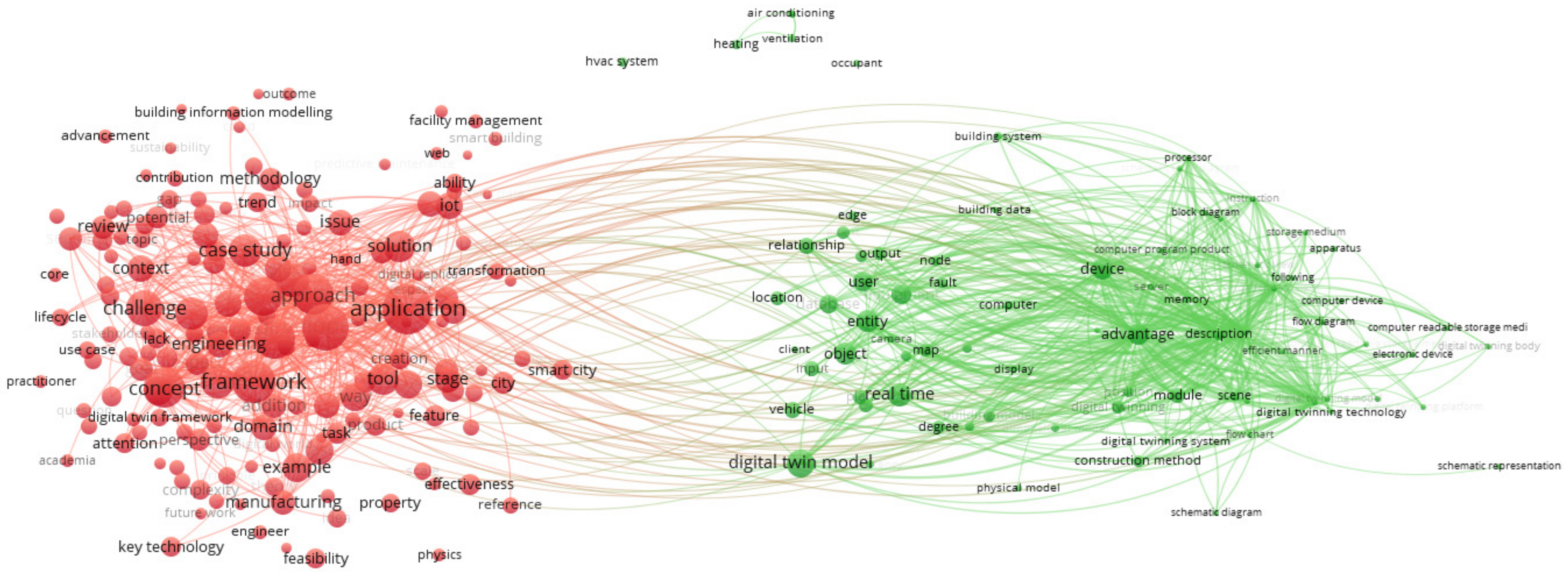
:1. Introduction
2. The Implementation of Digital Twin for Energy Using
2.1. The Digital Twin Composition
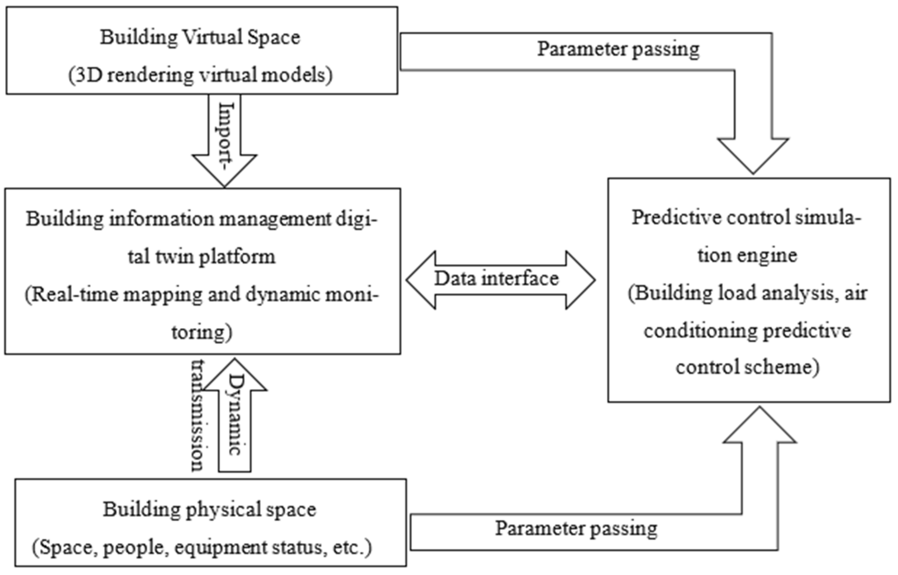
2.2. Implementation Method of Digital Twin System for Building Management
3. The Building Information Monitoring Case Base on DTT
3.1. Building Introduction
3.2. Digital Twin Operation and Maintenance Platform
- (1)
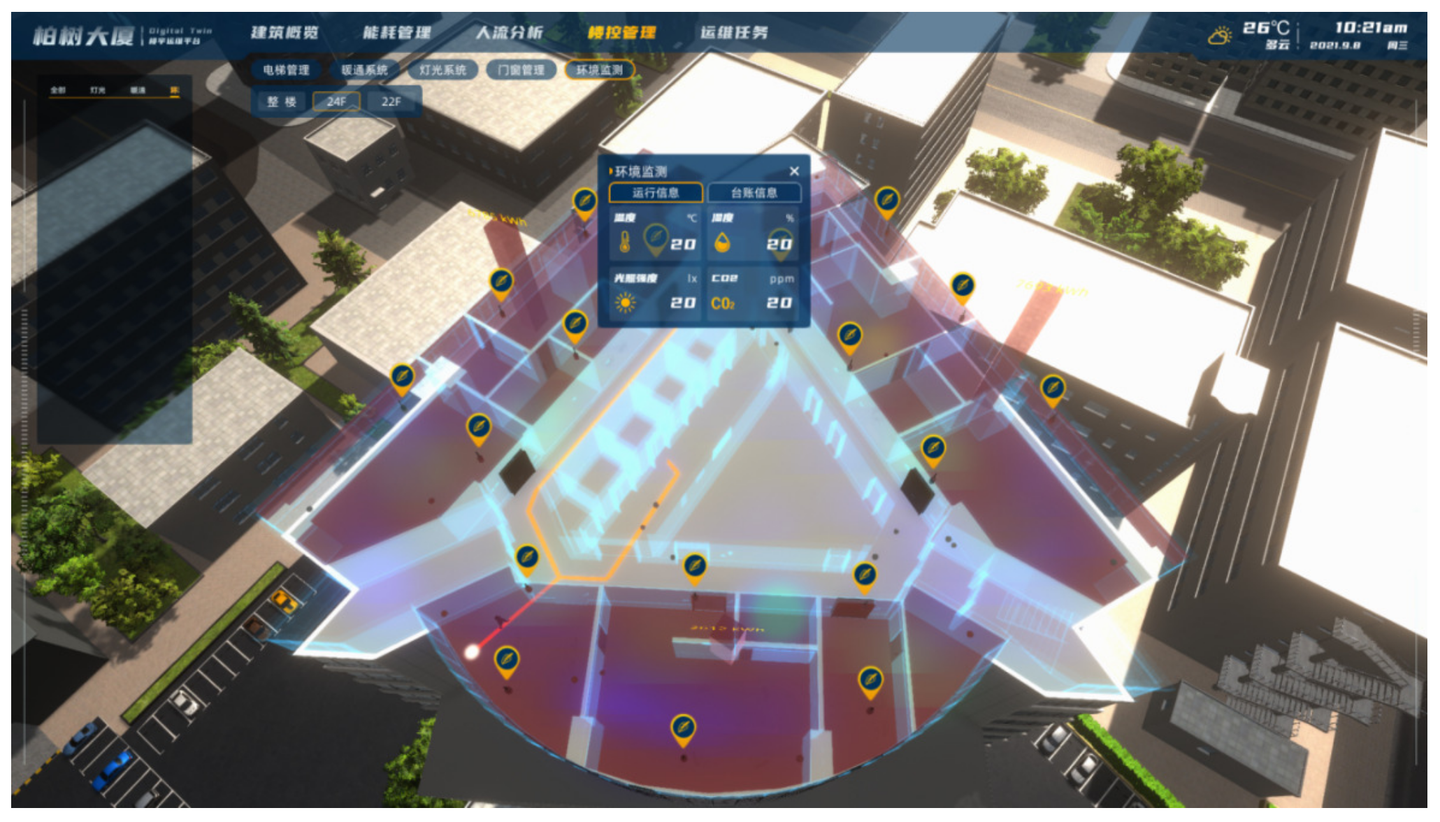
- Indoor environment monitoring system
- (2)
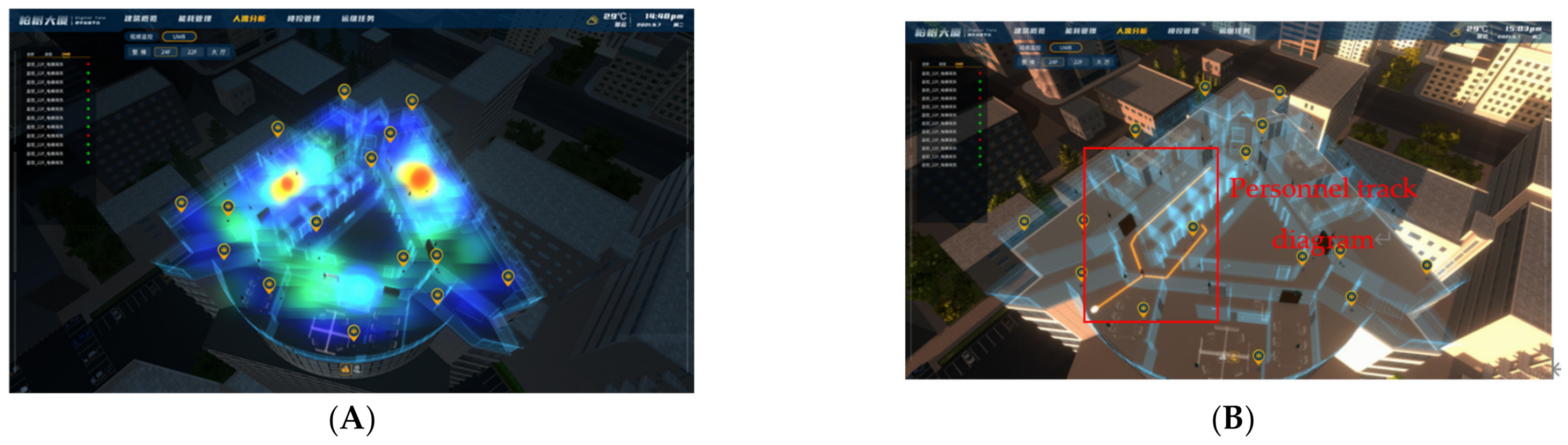
- Personnel location system
- (3)
- Door and window intelligent management system
- (4)
- Lighting intelligent management system
- (5)
- HVAC intelligent management system
- (6)
- Building energy consumption monitoring and management
4. Building Energy-Saving Verification for Energy System Monitoring and Management
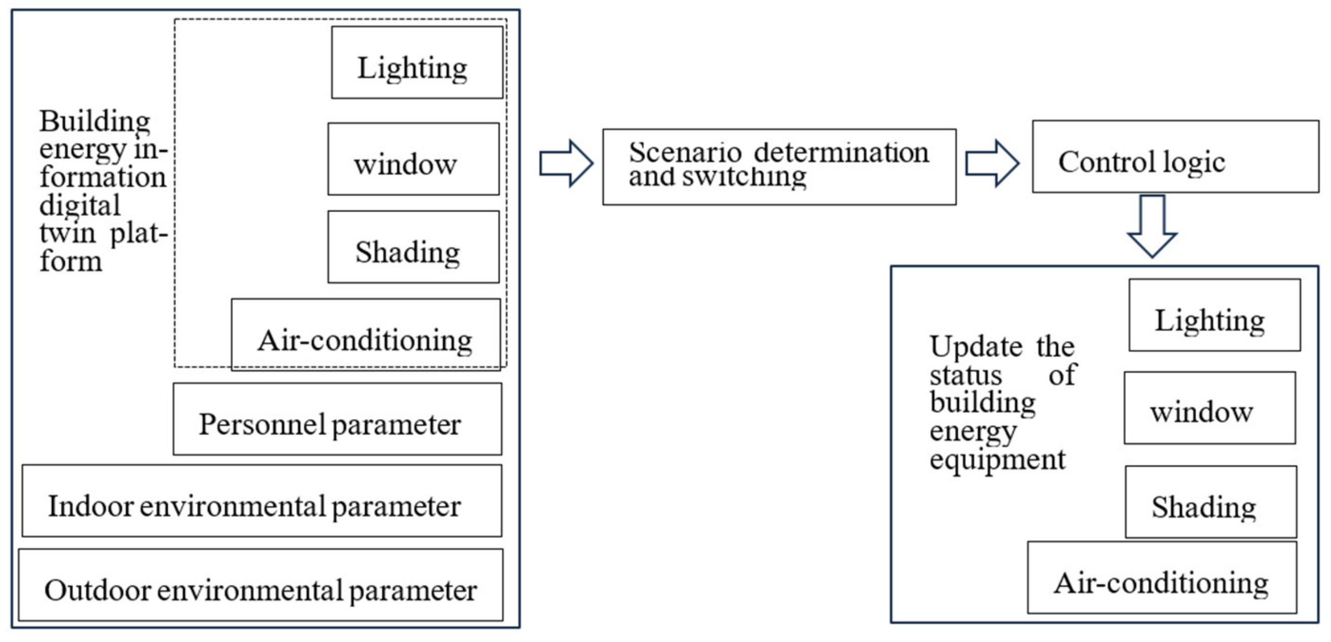
4.1. Intelligent Control Flow for Building Energy Using
4.2. Energy-Saving Verification for Building Energy Using Intelligent Control
- (1)
- Simulation parameter design
- (2)
- Simulation results and analysis for energy consumption
5. Conclusions
Author Contributions
Funding
Data Availability Statement
Conflicts of Interest
References
- Wang, C. Research on Human Behavior Simulation for Building Energy Use. Ph.D. Thesis, Tsinghua University, Beijing, China, November 2014. [Google Scholar]
- Tao, F.; Liu, W.; Liu, J.; Liu, X. Exploration of digital twin and its application. Comput. Integr. Manuf. Syst. 2018, 24, 1–18. [Google Scholar]
- Zhuang, C.; Liu, J.; Xiong, H.; Xiong, H.; Ding, X.; Ling, S.; Wong, G. The connotation, architecture and development trend of product digital twin. Comput. Integr. Manuf. Syst. 2017, 23, 753–768. [Google Scholar]
- Liu, D.; Guo, K.; Wang, B.; Peng, Y. Overview and prospect of digital twin technology. Chin. J. Instrum. 2018, 39, 1–10. [Google Scholar]
- White, G.; Zink, A.; Codecá, L.; Clarke, S. A digital twin smart city for citizen feedback. Cities 2021, 110, 103064. [Google Scholar] [CrossRef]
- Liu, X.; Wang, J.; Shang, G.; Wu, F.; Zhang, A.; Su, J.; Tang, T. A preliminary study of digital twin technology in spaceport. J. Northwestern Polytech. Univ. 2019, 37, 114–119. [Google Scholar]
- Ford, D.N.; Wolf, C.M. Smart Cities with Digital Twin Systems for Disaster Management. J. Manag. Eng. 2020, 36, 04020027. [Google Scholar] [CrossRef]
- Boje, C.; Guerriero, A.; Kubicki, S.; Rezgui, Y. Towards a semantic Construction Digital Twin: Directions for future research. Autom. Constr. 2020, 114, 103179. [Google Scholar] [CrossRef]
- Ding, K.; Zhang, X.; Zhou, H.; Wang, C.; Yang, H.; Zhang, F.; Cao, X. Multi-dimensional and multi-scale intelligent manufacturing space based on digital twin and its modeling method. Comput. Integr. Manuf. Syst. 2019, 25, 1491–1504. [Google Scholar]
- Wang, Y.; Chen, Y.; Wang, W. Design and application of green building operation cost management system based on digital twin. Build. Energy Sav. 2020, 9, 64–70. [Google Scholar]
- Hunhevicz, J.J.; Motie, M.; Hall, D.M. Digital building twins and blockchain for performance-based (smart) contracts. Autom. Constr. 2022, 133, 103981. [Google Scholar] [CrossRef]
- Angjeliu, G.; Coronelli, D.; Cardani, G. Development of the simulation model for Digital Twin applications in historical masonry buildings: The integration between numerical and experimental reality. Comput. Struct. 2020, 238, 106282. [Google Scholar] [CrossRef]
- Lydon, G.P.; Caranovic, S.; Hischier, I.; Schlueter, A. Coupled simulation of thermally active building systems to support a digital twin. Energy Build. 2019, 202, 109298. [Google Scholar] [CrossRef]
- Wang, W.; Guo, H.; Li, X. Deep learning for assessment of environmental satisfaction using BIM big data in energy efficient building digital twins. Sustain. Energy Technol. Assess. 2022, 50, 101897. [Google Scholar] [CrossRef]
- Zhao, J.; Feng, H.; Chen, Q. Developing a conceptual framework for the application of digital twin technologies to revamp building operation and maintenance processes. J. Build. Eng. 2022, 49, 104028. [Google Scholar] [CrossRef]
- He, B.; Wang, F.; Wang, Z. Architectural Digital Twin Application Based on UWB Positioning System. Archit. Techniqu. 2019, 9, 46–48. [Google Scholar]


| Building | Constituent | Heat Transfer Coefficient | Shading Factor |
|---|---|---|---|
| Roofing | Crushed stone concrete (50.0 mm) + Cement mortar (20.0 mm) + Foam glass (70.0 mm) + 1:8 Cement aerated concrete scraps (20.0 mm) + Rebar concrete (120.0 mm) | 0.68 | / |
| Outer wall | Cement mortar (20.0 mm) + Rock wool tape (40.0 mm) + Cement mortar (20.0 mm) + Porous concrete brick (200.0 mm) | 1.0 | / |
| Exterior window | Metal insulation profile (Height of insulation strip 20 mm) (5 Low-E + 12 A + 5) | 2.5 | 0.4 |
| Functional Area | Summer | Winter | Fresh Air Volume |
|---|---|---|---|
| Office room | 26 °C | 20 | 30 m3/h·p |
| Hall | 25 | 18 | / |
| Cooling Energy Consumption (kWh) | Heating Energy Consumption (kWh) | Lighting Energy Consumption (kWh) | Equipment Energy Consumption (kWh) | Total Energy Consumption (kWh) | |
|---|---|---|---|---|---|
| No intelligent control system | 3,411,812.33 | 1,479,888.04 | 1,589,092.85 | 738,846.59 | 7,219,639.81 |
| Intelligent control system applications | 3,180,358.7 | 1,211,976.97 | 1,589,092.85 | 738,846.59 | 6,720,275.11 |
| Energy consumption Comparison | −6.78% | −18.10% | 0.00% | 0.00% | −6.92% |
| Cooling Energy Consumption (kWh) | Heating Energy Consumption (kWh) | Lighting Energy Consumption (kWh) | Equipment Energy Consumption (kWh) | Total Energy Consumption (kWh) | |
|---|---|---|---|---|---|
| No intelligent control system | 3,411,812.33 | 1,479,888.04 | 1,589,092.85 | 738,846.59 | 7,219,639.81 |
| Intelligent control system applications | 2,628,972.13 | 1,816,202.4 | 283,331.2 | 738,846.59 | 5,467,352.32 |
| Energy consumption Comparison | −22.94% | 22.73% | −82.17% | 0.00% | −24.27% |
| Cooling Energy Consumption (kWh) | Heating Energy Consumption (kWh) | Lighting Energy Consumption (kWh) | Equipment Energy Consumption (kWh) | Total Energy Consumption (kWh) | |
|---|---|---|---|---|---|
| No intelligent control system | 3,411,812.33 | 1,479,888.04 | 1,589,092.85 | 738,846.59 | 7,219,639.81 |
| Intelligent control system applications | 3,241,677.3 | 1,480,365.73 | 1,603,342.22 | 738,846.59 | 7,064,231.84 |
| Energy consumption Comparison | −4.99% | 0.03% | 0.90% | 0.00% | −2.15% |
| Cooling Energy Consumption (kWh) | Heating Energy Consumption (kWh) | Lighting Energy Consumption (kWh) | Equipment Energy Consumption (kWh) | Total Energy Consumption (kWh) | |
|---|---|---|---|---|---|
| No intelligent control system | 3,411,812.33 | 1,479,888.04 | 1,589,092.85 | 738,846.59 | 7,219,639.81 |
| Intelligent control system applications | 2,339,640.75 | 1,583,489.31 | 318,117.48 | 738,846.59 | 4,980,094.13 |
| Energy consumption Comparison | −31.43% | 7.00% | −79.98% | 0.00% | −31.02% |
Disclaimer/Publisher’s Note: The statements, opinions and data contained in all publications are solely those of the individual author(s) and contributor(s) and not of MDPI and/or the editor(s). MDPI and/or the editor(s) disclaim responsibility for any injury to people or property resulting from any ideas, methods, instructions or products referred to in the content. |
© 2023 by the authors. Licensee MDPI, Basel, Switzerland. This article is an open access article distributed under the terms and conditions of the Creative Commons Attribution (CC BY) license (https://creativecommons.org/licenses/by/4.0/).
Share and Cite
Li, C.; Lu, P.; Zhu, W.; Zhu, H.; Zhang, X. Intelligent Monitoring Platform and Application for Building Energy Using Information Based on Digital Twin. Energies 2023, 16, 6839. https://doi.org/10.3390/en16196839
Li C, Lu P, Zhu W, Zhu H, Zhang X. Intelligent Monitoring Platform and Application for Building Energy Using Information Based on Digital Twin. Energies. 2023; 16(19):6839. https://doi.org/10.3390/en16196839
Chicago/Turabian StyleLi, Cui, Ping Lu, Weiran Zhu, Han Zhu, and Xinmin Zhang. 2023. "Intelligent Monitoring Platform and Application for Building Energy Using Information Based on Digital Twin" Energies 16, no. 19: 6839. https://doi.org/10.3390/en16196839