
Solar Energy Harnessing Technologies towards De-Carbonization: A Systematic Review of Processes and Systems

Abstract
:1. Introduction
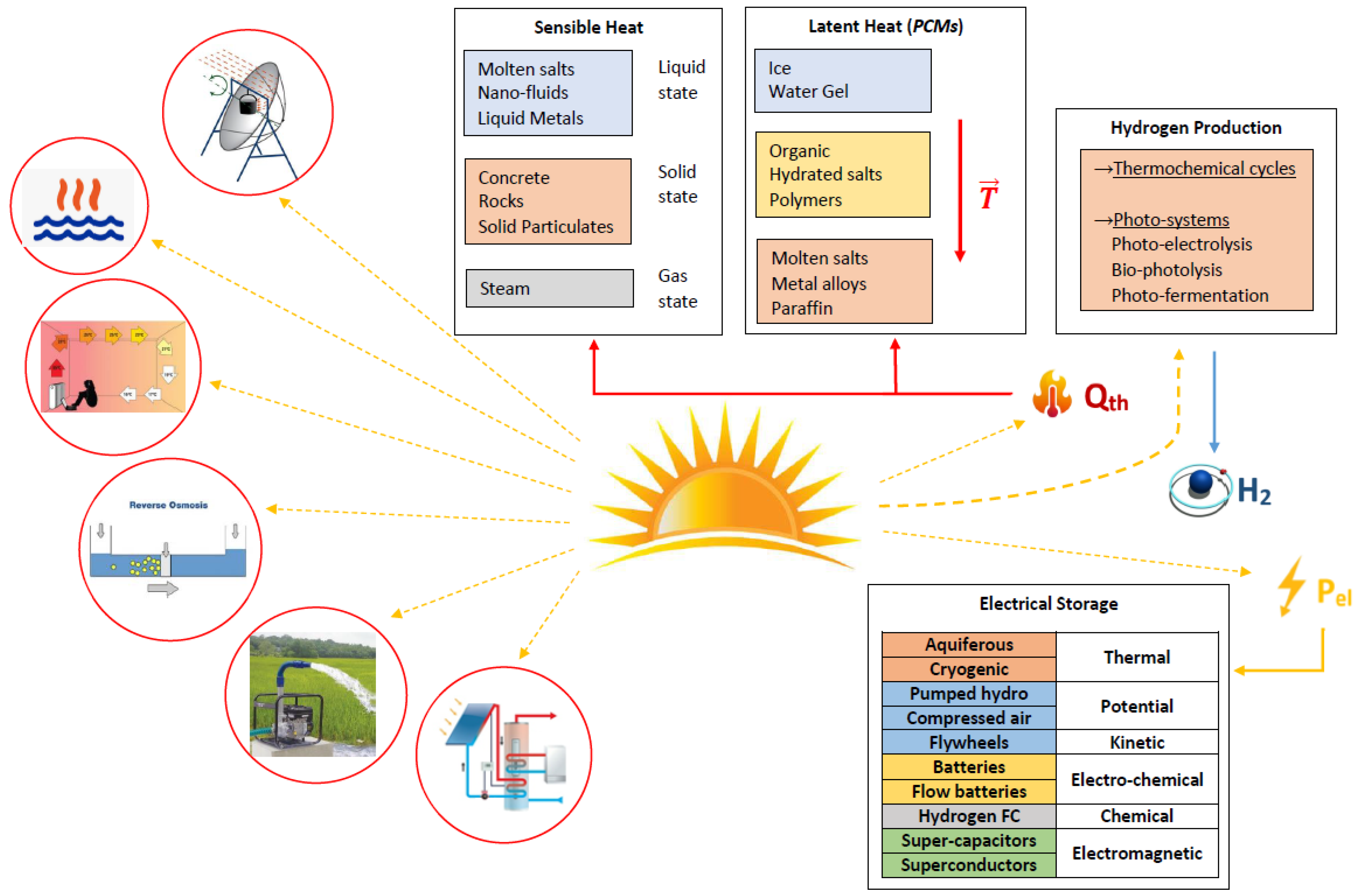
2. Direct Harnessing Systems
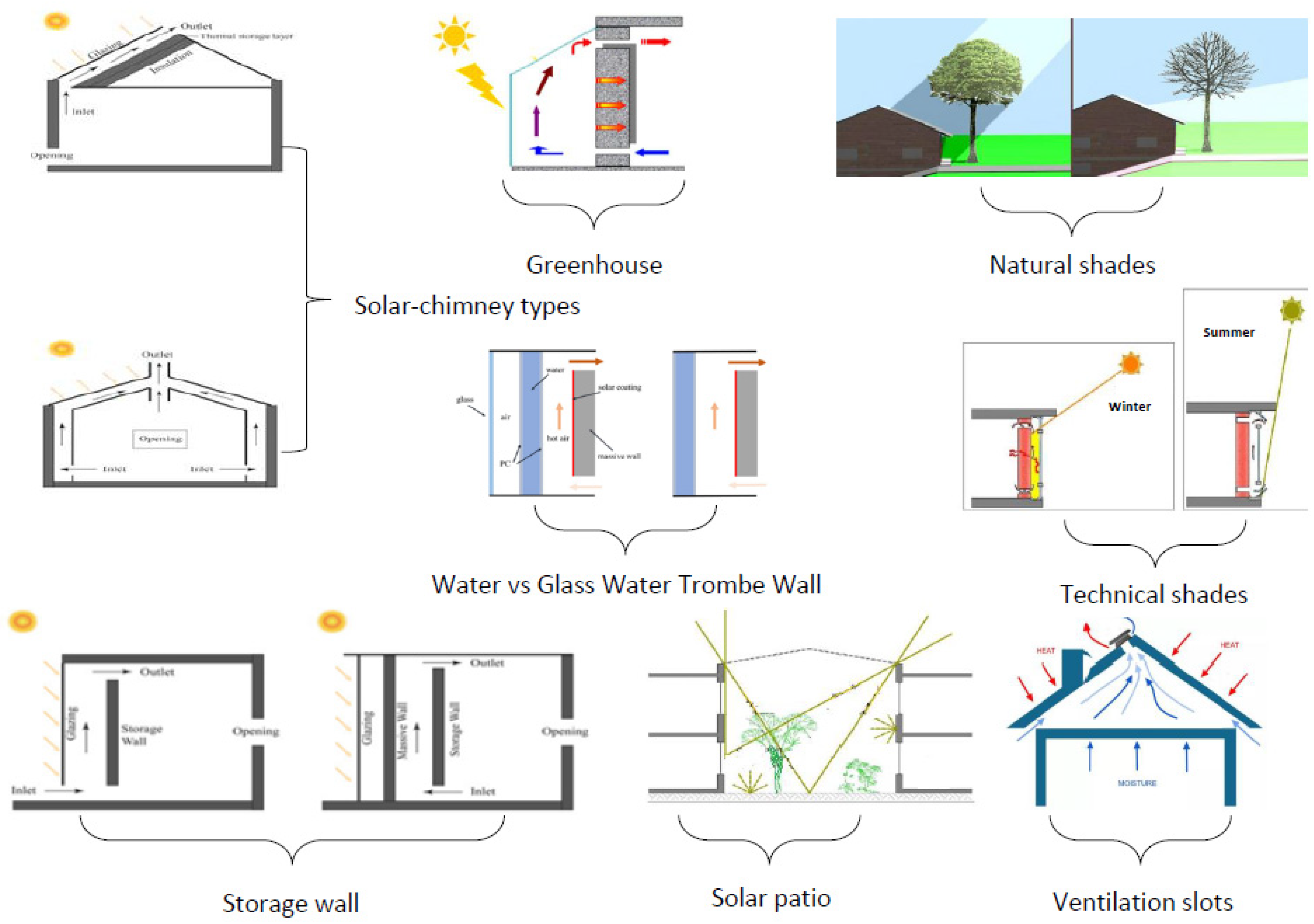
2.1. Space Heating/Cooling
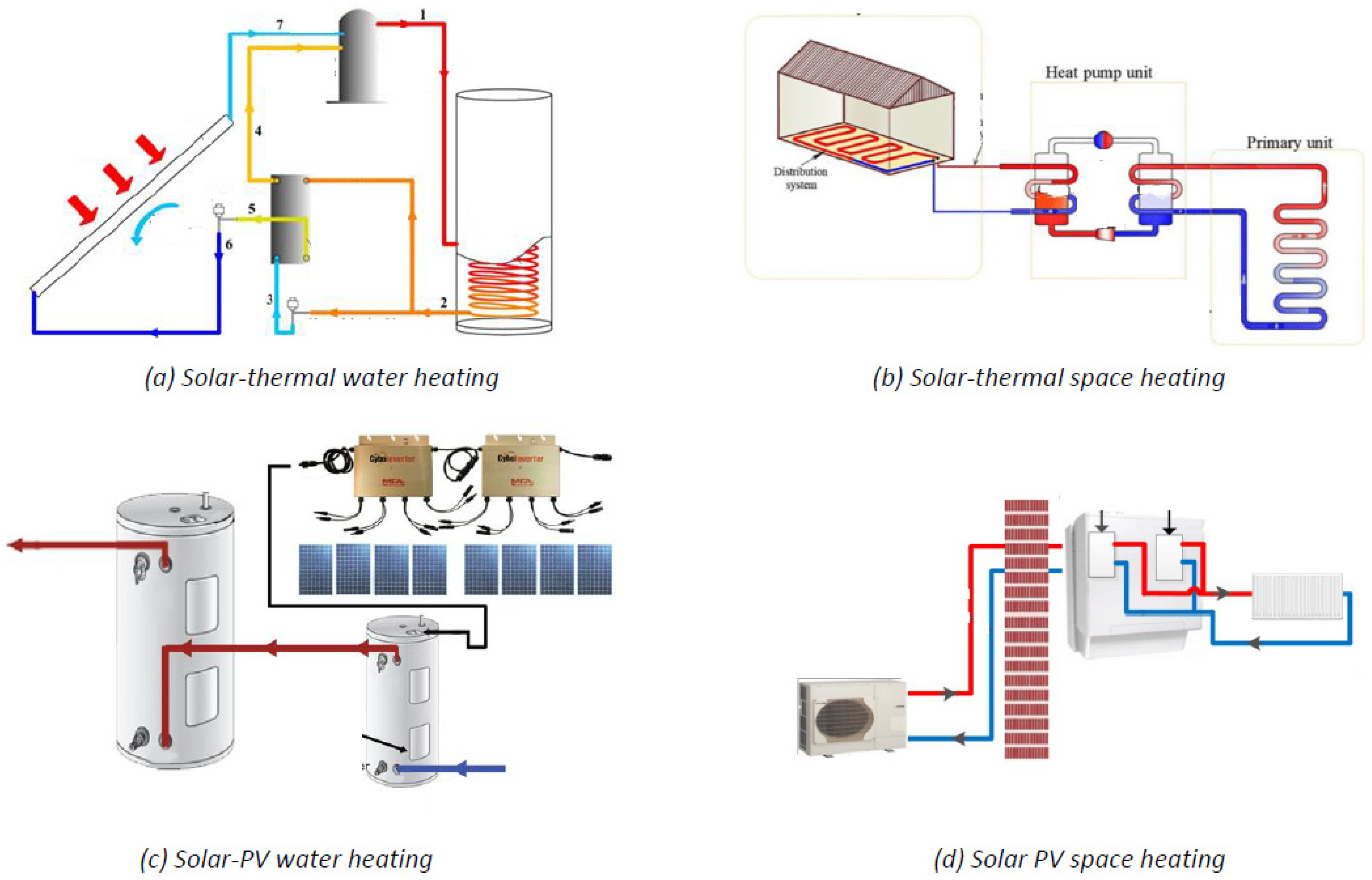
2.2. Domestic Water for Use or Space Heating
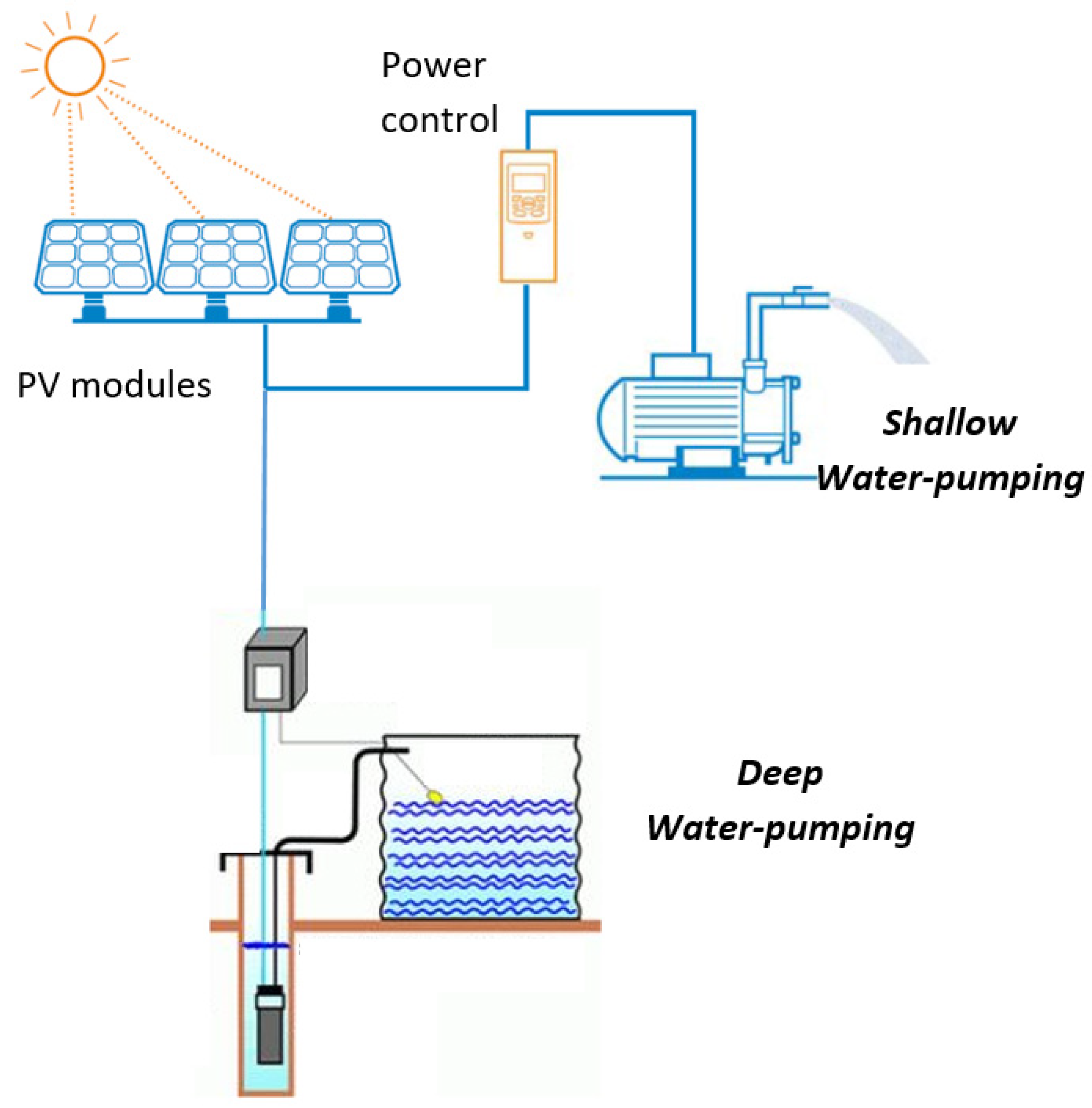
2.3. Water Pumping
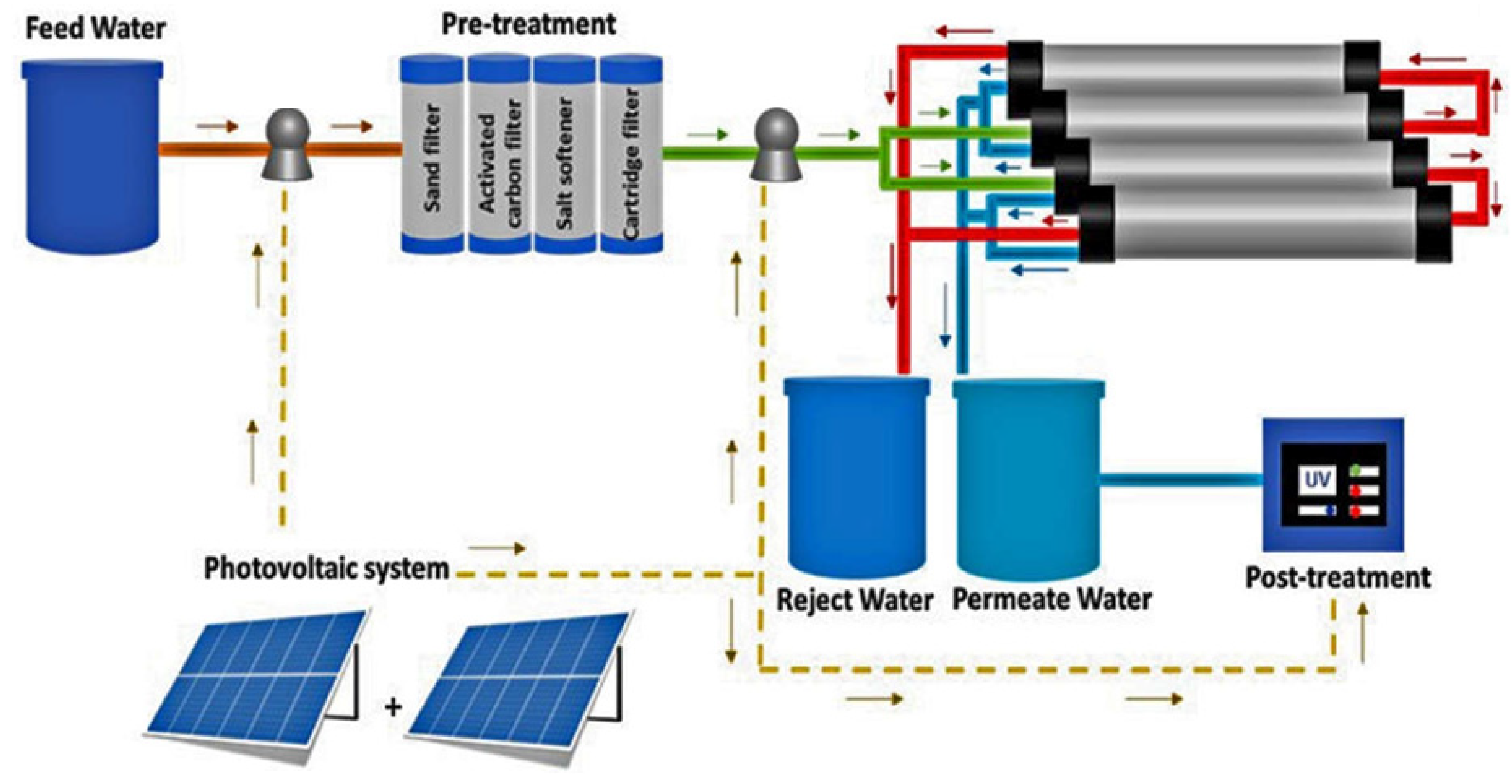
2.4. Seawater Desalination
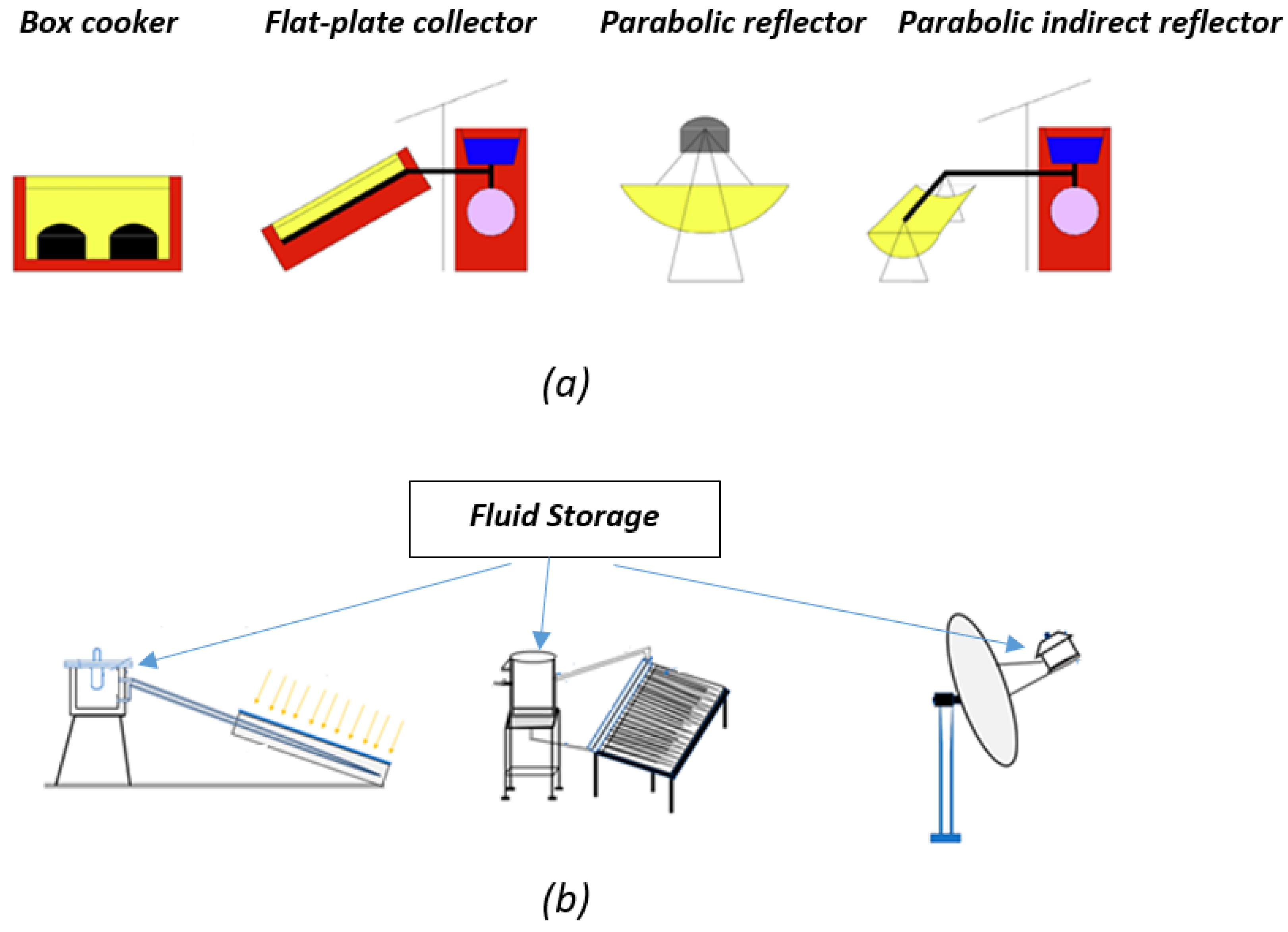
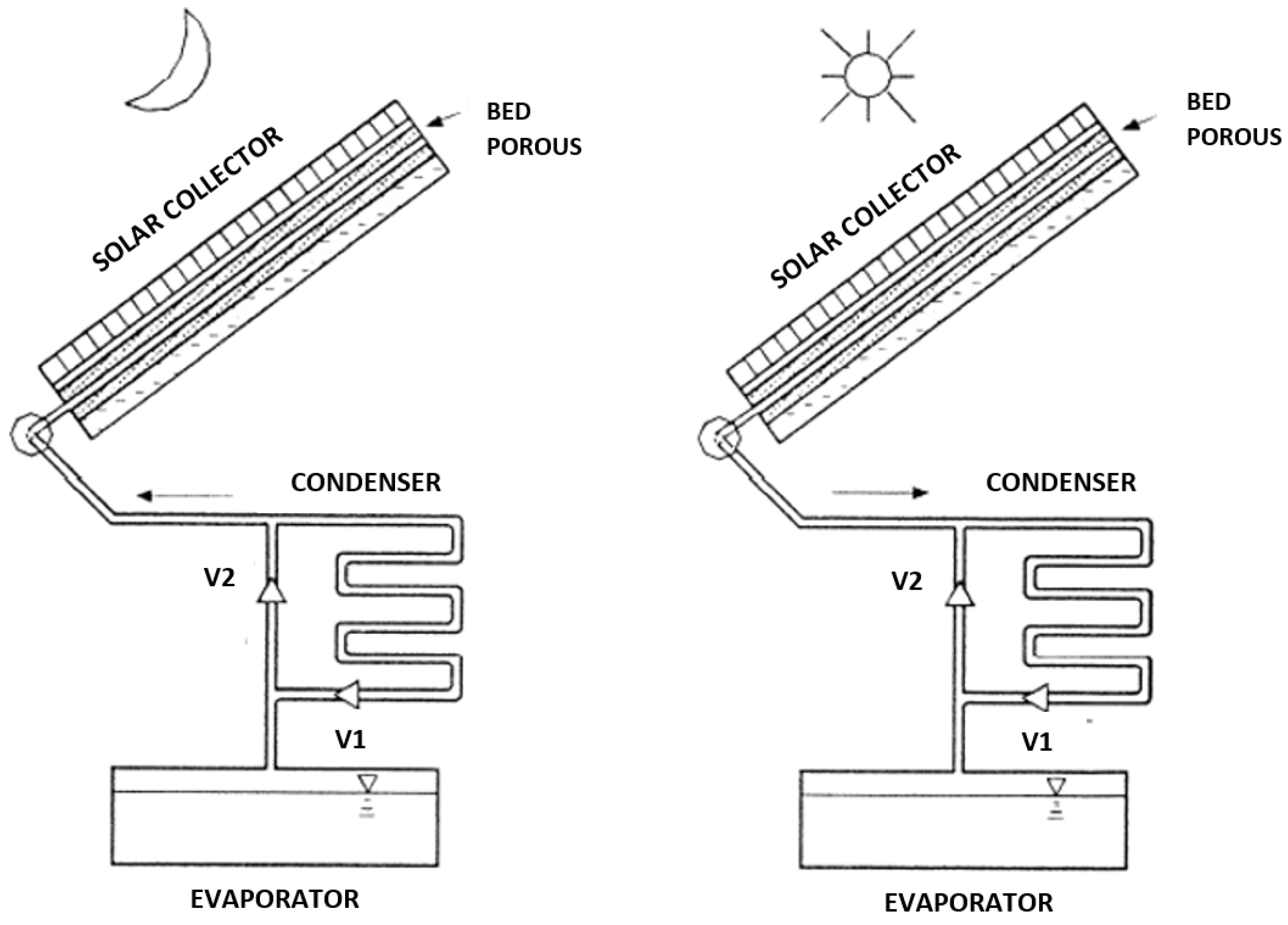
2.5. Solar Cooking
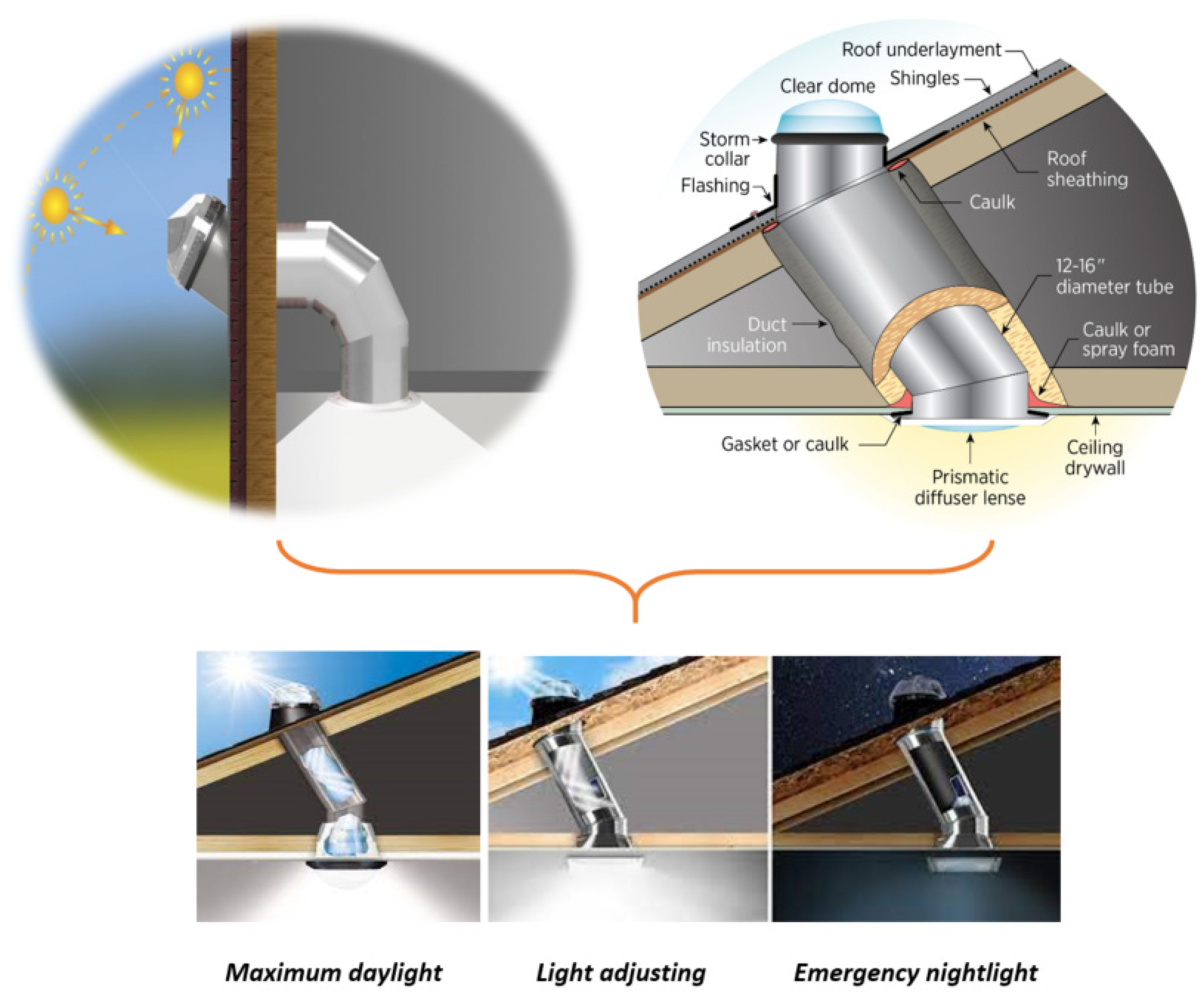
2.6. Solar Lighting
3. Thermal Storage Systems
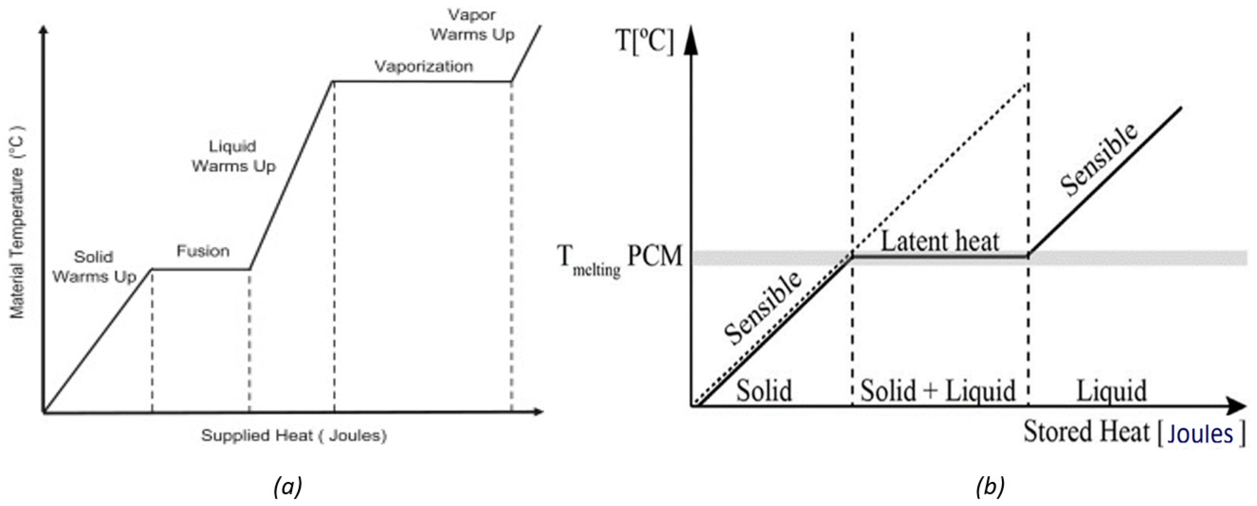
3.1. Sensible Heat
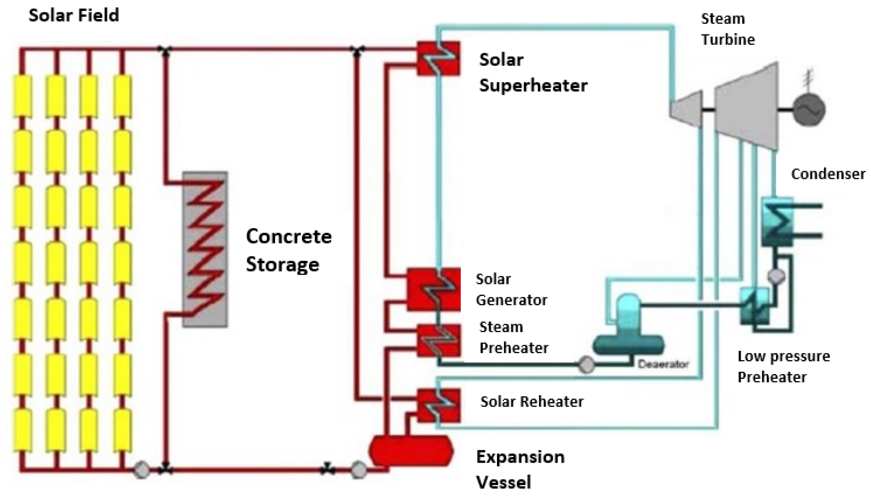
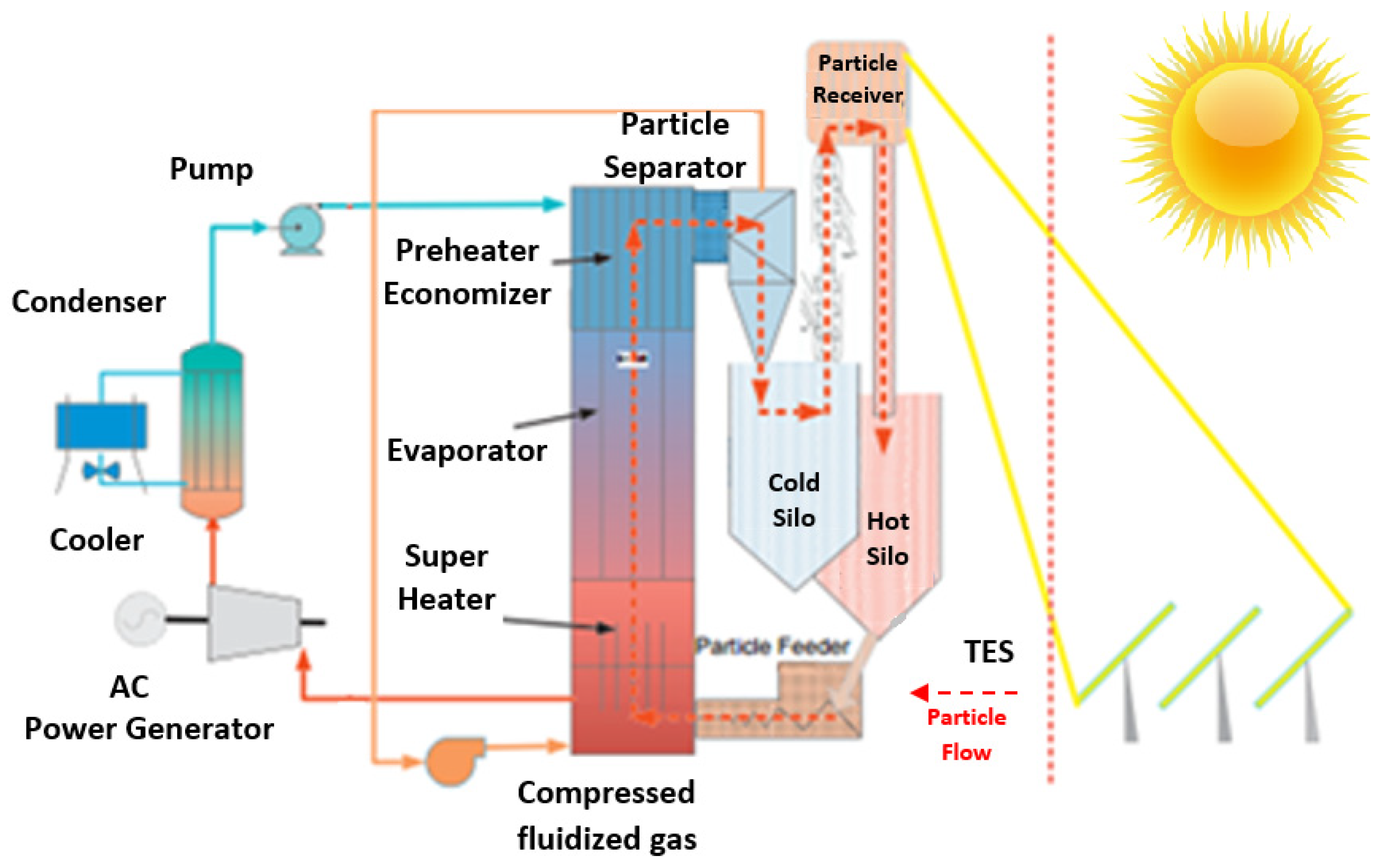
- Solid storage involves storing solar heat in solid materials such as stones, concrete, or bricks. These materials have a high thermal mass, which means they can store large amounts of heat for long periods of time. Solid storage is commonly used in passive solar buildings and some solar cooking systems.
- Liquid storage involves storing solar heat in liquids, such as water or oil. Liquid storage can be done either in a single tank or in two tanks (one for hot and one for cold fluids) connected by a heat exchanger. Liquid storage is commonly used in active solar heating and cooling systems.
- Gaseous storage involves storing solar heat in superheated gases, including steam. PCMs have a high energy density, which means they can store large amounts of heat in a small volume. Although they are commonly used in solar thermal energy storage systems for residential and commercial applications, sensible heat storage constitutes a retrospective procedure following the latent heat process (which is achieved by utilizing PCMs) in larger-scale industrial and energy-intensive plants.
3.1.1. Solid-State Thermal Storage
3.1.2. Liquid-State Thermal Storage
3.2. Latent Heat
4. Electricity Storage Systems
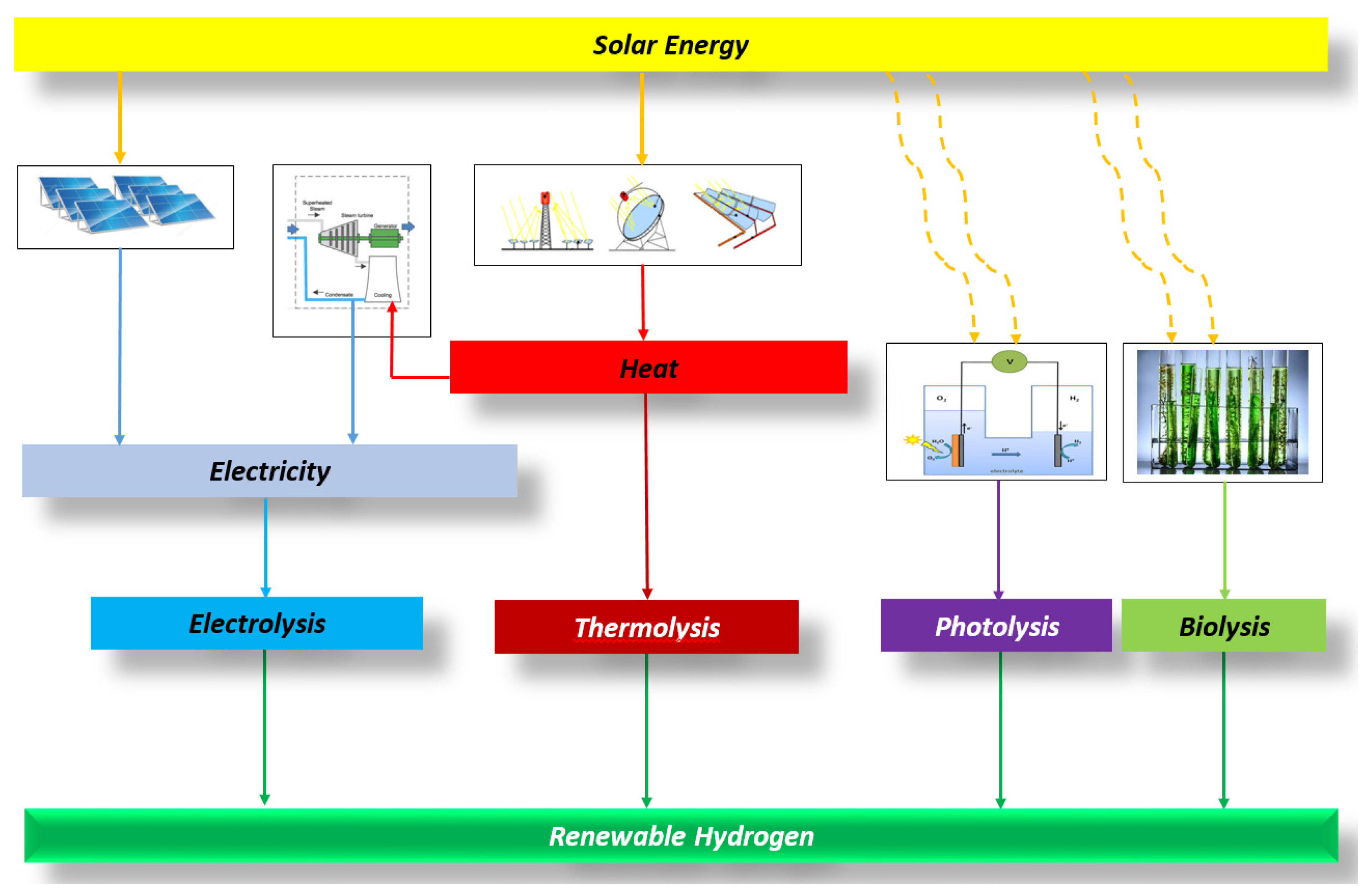
5. Hydrogen Storage Systems
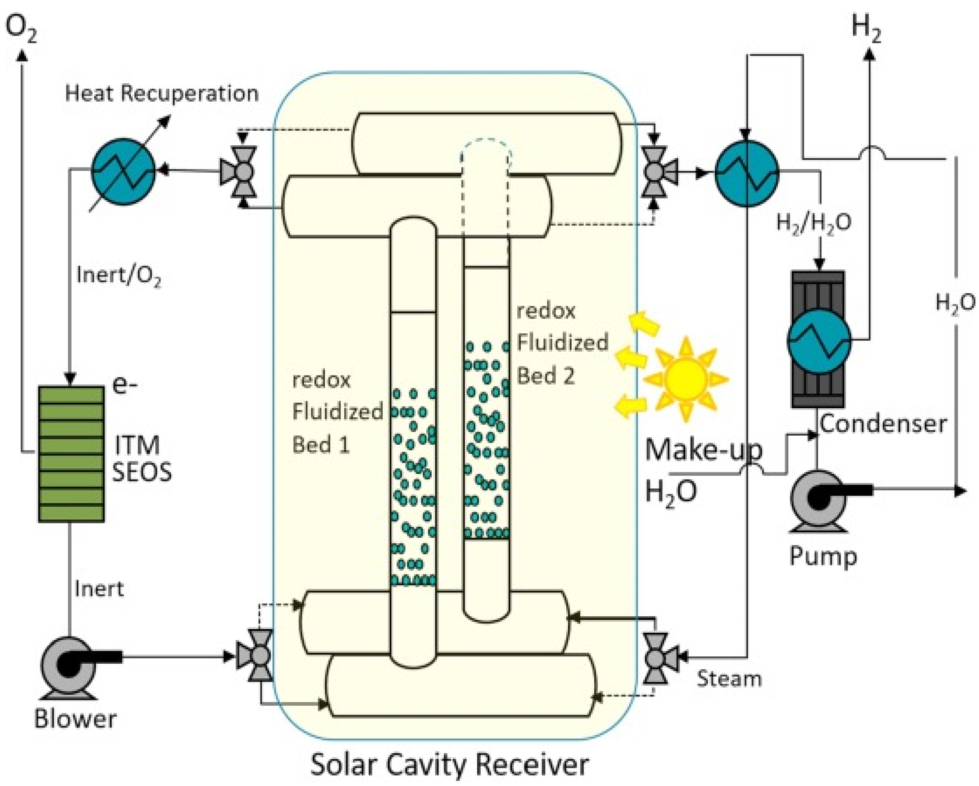
5.1. Thermochemical Cycles
5.2. Photosystems
6. Conclusions
Funding
Data Availability Statement
Conflicts of Interest
Appendix A

| Technology | Daily Self-Discharge (%) | Lifetime (Years) | Cycling Times (Cycles) | Round-Trip Efficiency (%) | DoD (%) | Response Time | Suitable Storage Duration |
|---|---|---|---|---|---|---|---|
| PHES | almost 0 | 30–50 | 10,000–30,000 | 70–85 | 95 | min | hours-months |
| CAES | almost 0 | 30 | 8000–12,000 | 42–54 | 100 | min | hours-months |
| TES | >50 | >25 | 50,000 | 40–50 | 100 | s-min | 3 h |
| FES | 55–100 | 20 | 105–107 | 90–95 | 100 | ms | secs-mins |
| SES | 40–60 | - | 106 | 23 | 100 | ms | mins-hours |
| GES | 10 | - | 106 | 80 | 80 | s | mins-hours |
| Pb-acid | 0.1–0.2 | 5–15 | 200–2000 | 85–90 | 80 | ms | mins-days |
| Ni-Cd | 0.1–0.2 | 10–20 | 1500–3000 | 60–90 | 100 | ms | mins-days |
| Zn-air | almost 0 | 0.17–30 | 100–300 | 50 | 100 | min | hours-months |
| Na-S | almost 0 | 10–15 | 1500–5000 | 89–92 | 100 | ms | secs-hours |
| ZEBRA | 20 | 10–14 | 1000 | 70–85 | 80 | - | secs-hours |
| Li-ion | 0.03 | 5–15 | 3000–10,000 | ~100 | 80 | ms | mins-days |
| VRB | almost 0 | 5–10 | >16,000 | 85 | 100 | ms | hours-months |
| Zn-Br | almost 0 | 5–10 | 2000–3500 | 75 | 100 | ms | hours-months |
| PSB | almost 0 | 10–15 | 800–2000 | 75 | 100 | ms | hours-months |
| HES | 0.06–3 | 5–15 | 20,000 | 20–50 | 90 | s | hours-months |
| SCES | 20–40 | 10–12 | 106 | 85–98 | 100 | ms | secs-hours |
| SMES | 10–15 | >20 | almost ∞ | 95 | 100 | ms | ≤30 min |
References
- Nikolaidis, P.; Poullikkas, A. A Thorough Emission-Cost Analysis of the Gradual Replacement of Carbon-Rich Fuels with Carbon-Free Energy Carriers in Modern Power Plants: The Case of Cyprus. Sustainability 2022, 14, 10800. [Google Scholar] [CrossRef]
- Zhang, J.; Xu, L.; Shabunko, V.; Tay, S.E.R.; Sun, H.; Lau, S.S.Y.; Reindl, T. Impact of urban block typology on building solar potential and energy use efficiency in tropical high-density city. Appl. Energy 2019, 240, 513–533. [Google Scholar] [CrossRef]
- Reames, T.G. Distributional disparities in residential rooftop solar potential and penetration in four cities in the United States. Energy Res. Soc. Sci. 2020, 69, 101612. [Google Scholar] [CrossRef]
- Stecca, M.; Elizondo, L.R.; Soeiro, T.B.; Bauer, P.; Palensky, P. A comprehensive review of the integration of battery energy storage systems into distribution networks. IEEE Open J. Ind. Electron. Soc. 2020, 1, 46–65. [Google Scholar] [CrossRef]
- Gabrielli, P.; Poluzzi, A.; Kramer, G.J.; Spiers, C.; Mazzotti, M.; Gazzani, M. Seasonal energy storage for zero-emissions multi-energy systems via underground hydrogen storage. Renew. Sustain. Energy Rev. 2020, 121, 109629. [Google Scholar] [CrossRef]
- Budin, L.; Grdenić, G.; Delimar, M. A quadratically constrained optimization problem for determining the optimal nominal power of a pv system in net-metering model: A case study for Croatia. Energies 2021, 14, 1746. [Google Scholar] [CrossRef]
- Nikolaidis, P.; Poullikkas, A. Increasing the Photovoltaic Hosting Capacity in Autonomous Grids and Microgrids via Enhanced Priority-List Schemes and Storage. Green Energy Sustain. 2021, 1, 1–21. [Google Scholar] [CrossRef]
- Garlík, B.; Křivan, M. Renewable energy unit commitment, with different acceptance of balanced power, solved by simulated annealing. Energy Build. 2013, 67, 392–402. [Google Scholar] [CrossRef]
- Nikolaidis, P. Sustainable Routes for Renewable Energy Carriers in Modern Energy Systems. In Bioenergy Research: Commercial Opportunities & Challenges; Springer: Singapore, 2021; pp. 247–323. Available online: http://www.springer.com/series/16486 (accessed on 10 August 2023).
- Tounta, E.-N. Green Smart Home: Systems, Materials and Simulation Design. 2022. Available online: https://polynoe.lib.uniwa.gr/xmlui/handle/11400/2798 (accessed on 6 August 2023).
- Dan, D.; Tanasa, C.; Stoian, V.; Brata, S.; Stoian, D.; Nagy Gyorgy, T.; Florut, S.C. Passive house design-An efficient solution for residential buildings in Romania. Energy Sustain. Dev. 2016, 32, 99–109. [Google Scholar] [CrossRef]
- Müller, L.; Berker, T. Passive House at the crossroads: The past and the present of a voluntary standard that managed to bridge the energy efficiency gap. Energy Policy 2013, 60, 586–593. [Google Scholar] [CrossRef]
- Zacharopoulou, K. Passive Buildings as Models for Energy Upgrade of Buildings in Greece; University of West Attica: Aigaleo, Greece, 2021. [Google Scholar]
- Georgiou, G.S.; Nikolaidis, P.; Lazari, L.; Christodoulides, P. A Genetic Algorithm Driven Linear Programming for Battery Optimal Scheduling in nearly Zero Energy Buildings. In Proceedings of the 2019 54th International Universities Power Engineering Conference, UPEC 2019—Proceedings, Bucharest, Romania, 3–6 September 2019; pp. 1–6. [Google Scholar] [CrossRef]
- Silva, S.M.; Mateus, R.; Marques, L.; Ramos, M.; Almeida, M. Contribution of the solar systems to the nZEB and ZEB design concept in Portugal—Energy, economics and environmental life cycle analysis. Sol. Energy Mater. Sol. Cells 2016, 156, 59–74. [Google Scholar] [CrossRef]
- Irfan, M.; Abas, N.; Saleem, M.S. Net Zero Energy Buildings (NZEB): A Case Study of Net Zero Energy Home in Pakistan. In Proceedings of the 2018 International Conference on Power Generation Systems and Renewable Energy Technologies (PGSRET), Islamabad, Pakistan, 10–12 September 2018; pp. 1–6. [Google Scholar] [CrossRef]
- Georgiou, G.S.; Nikolaidis, P.; Kalogirou, S.A.; Christodoulides, P. A hybrid optimization approach for autonomy enhancement of nearly-zero-energy buildings based on battery performance and artificial neural networks. Energies 2020, 13, 3680. [Google Scholar] [CrossRef]
- da Cunha, S.R.L.; de Aguiar, J.L.B. Phase change materials and energy efficiency of buildings: A review of knowledge. J. Energy Storage 2020, 27, 101083. [Google Scholar] [CrossRef]
- Bontemps, A.; Ahmad, M.; Johanns, K.; Sallée, H. Experimental and modelling study of twin cells with latent heat storage walls. Energy Build. 2011, 43, 2456–2461. [Google Scholar] [CrossRef]
- Mekhilef, S.; Saidur, R.; Safari, A. A review on solar energy use in industries. Renew. Sustain. Energy Rev. 2011, 15, 1777–1790. [Google Scholar] [CrossRef]
- Zhou, X.; Xu, Y.; Zhang, X.; Xu, D.; Linghu, Y.; Guo, H.; Wang, Z.; Chen, H. Large scale underground seasonal thermal energy storage in China. J. Energy Storage 2021, 33, 102026. [Google Scholar] [CrossRef]
- Zayed, M.E.; Zhao, J.; Elsheikh, A.H.; Hammad, F.A.; Ma, L.; Du, Y.; Kabeel, A.E.; Shalaby, S.M. Applications of cascaded phase change materials in solar water collector storage tanks: A review. Sol. Energy Mater. Sol. Cells 2019, 199, 24–49. [Google Scholar] [CrossRef]
- Kumar, L.; Hasanuzzaman, M.; Rahim, N.A. Global advancement of solar thermal energy technologies for industrial process heat and its future prospects: A review. Energy Convers. Manag. 2019, 195, 885–908. [Google Scholar] [CrossRef]
- Hu, M.; Zhao, B.; Ao, X.; Ren, X.; Cao, J.; Wang, Q.; Su, Y.; Pei, G. Performance assessment of a trifunctional system integrating solar PV, solar thermal, and radiative sky cooling. Appl. Energy 2020, 260, 114167. [Google Scholar] [CrossRef]
- Ge, T.S.; Wang, R.Z.; Xu, Z.Y.; Pan, Q.W.; Du, S.; Chen, X.M.; Ma, T.; Wu, X.N.; Sun, X.L.; Chen, J.F. Solar heating and cooling: Present and future development. Renew. Energy 2018, 126, 1126–1140. [Google Scholar] [CrossRef]
- Mustafa Omer, A. Ground-source heat pumps systems and applications. Renew. Sustain. Energy Rev. 2008, 12, 344–371. [Google Scholar] [CrossRef]
- Schibuola, L.; Scarpa, M. Experimental analysis of the performances of a surface water source heat pump. Energy Build. 2016, 113, 182–188. [Google Scholar] [CrossRef]
- Tan, Z.; Feng, X.; Wang, Y. Performance comparison of different heat pumps in low-temperature waste heat recovery. Renew. Sustain. Energy Rev. 2021, 152, 111634. [Google Scholar] [CrossRef]
- De Oliveira Turci, L.; Sun, H.; Bai, M.; Wang, J.; Hu, P. Water pump station scheduling optimization using an improved genetic algorithm approach. In Proceedings of the 2019 IEEE Congress on Evolutionary Computation (CEC), Wellington, New Zealand, 10–13 June 2019; pp. 944–951. [Google Scholar] [CrossRef]
- Subramaniam, U.; Dutta, N.; Padmanaban, S.; Almakhles, D.; Kyslan, K.; Fedak, V. Identification of sludge in water pumping system using support vector machine. In Proceedings of the 2019 International Conference on Electrical Drives & Power Electronics (EDPE), The High Tatras, Slovakia, 24–26 September 2019; pp. 403–408. [Google Scholar] [CrossRef]
- Pavlos, N. Sustainable services to enhance flexibility in the upcoming smart grids. In Sustaining Resources for Tomorrow; Springer: Cham, Switzrland, 2020; pp. 245–274. [Google Scholar] [CrossRef]
- Meah, K.; Fletcher, S.; Ula, S. Solar photovoltaic water pumping for remote locations. Renew. Sustain. Energy Rev. 2008, 12, 472–487. [Google Scholar] [CrossRef]
- Gao, X.; Liu, J.; Zhang, J.; Yan, J.; Bao, S.; Xu, H.; Qin, T. Feasibility evaluation of solar photovoltaic pumping irrigation system based on analysis of dynamic variation of groundwater table. Appl. Energy 2013, 105, 182–193. [Google Scholar] [CrossRef]
- Angadi, S. Comprehensive Review on Solar, Wind and Hybrid Wind-PV Water Pumping Systems-An Electrical Engineering Perspective. CPSS Trans. Power Electron. Appl. 2021, 6, 1–19. [Google Scholar] [CrossRef]
- Chandel, S.S.; Nagaraju Naik, M.; Chandel, R. Review of solar photovoltaic water pumping system technology for irrigation and community drinking water supplies. Renew. Sustain. Energy Rev. 2015, 49, 1084–1099. [Google Scholar] [CrossRef]
- Anand, B.; Shankar, R.; Murugavelh, S.; Rivera, W.; Midhun Prasad, K.; Nagarajan, R. A review on solar photovoltaic thermal integrated desalination technologies. Renew. Sustain. Energy Rev. 2021, 141, 110787. [Google Scholar] [CrossRef]
- Alawad, S.M.; Mansour, R.B.; Al-Sulaiman, F.A.; Rehman, S. Renewable energy systems for water desalination applications: A comprehensive review. Energy Convers. Manag. 2023, 286, 117035. [Google Scholar] [CrossRef]
- Tałałaj, I.A.; Biedka, P.; Bartkowska, I. Treatment of landfill leachates with biological pretreatments and reverse osmosis. Environ. Chem. Lett. 2019, 17, 1177–1193. [Google Scholar] [CrossRef]
- Adel, M.; Nada, T.; Amin, S.; Anwar, T.; Mohamed, A.A. Characterization of fouling for a full-scale seawater reverse osmosis plant on the Mediterranean sea: Membrane autopsy and chemical cleaning efficiency. Groundw. Sustain. Dev. 2022, 16, 100704. [Google Scholar] [CrossRef]
- Armendáriz-Ontiveros, M.M.; Dévora-Isiordia, G.E.; Rodríguez-López, J.; Sánchez-Duarte, R.G.; Álvarez-Sánchez, J.; Villegas-Peralta, Y.; Martínez-Macias, M. del R. Effect of Temperature on Energy Consumption and Polarization in Reverse Osmosis Desalination Using a Spray-Cooled Photovoltaic System. Energies 2022, 15, 7787. [Google Scholar] [CrossRef]
- Aramesh, M.; Ghalebani, M.; Kasaeian, A.; Zamani, H.; Lorenzini, G.; Mahian, O.; Wongwises, S. A review of recent advances in solar cooking technology. Renew. Energy 2019, 140, 419–435. [Google Scholar] [CrossRef]
- Sansaniwal, S.K.; Sharma, V.; Mathur, J. Energy and exergy analyses of various typical solar energy applications: A comprehensive review. Renew. Sustain. Energy Rev. 2018, 82, 1576–1601. [Google Scholar] [CrossRef]
- Lentswe, K.; Mawire, A.; Owusu, P.; Shobo, A. A review of parabolic solar cookers with thermal energy storage. Heliyon 2021, 7, e08226. [Google Scholar] [CrossRef]
- Mendoza, J.M.F.; Gallego-Schmid, A.; Schmidt Rivera, X.C.; Rieradevall, J.; Azapagic, A. Sustainability assessment of home-made solar cookers for use in developed countries. Sci. Total Environ. 2019, 648, 184–196. [Google Scholar] [CrossRef]
- Vanschoenwinkel, J.; Lizin, S.; Swinnen, G.; Azadi, H.; Van Passel, S. Solar cooking in Senegalese villages: An application of best-worst scaling. Energy Policy 2014, 67, 447–458. [Google Scholar] [CrossRef]
- Wu, Y. Research and development of solar light pipes in China. In Proceedings of the 2008 International Conference on Information Management, Innovation Management and Industrial Engineering, Taipei, Taiwan, 19–21 December 2008; Volume 3, pp. 146–149. [Google Scholar] [CrossRef]
- Mohapatra, B.N.; Ravi Kumar, M.; Mandal, S.K. Analysis of light tubes in interior daylighting system for building. Indones. J. Electr. Eng. Comput. Sci. 2019, 17, 710–719. [Google Scholar] [CrossRef]
- Nikolaidis, P.; Partaourides, H. A Model Predictive Control for the Dynamical Forecast of Operating Reserves in Frequency Regulation Services. Forecasting 2021, 3, 228–241. [Google Scholar] [CrossRef]
- Nikolaidis, P.; Poullikkas, A. A novel cluster-based spinning reserve dynamic model for wind and PV power reinforcement. Energy 2021, 234, 121270. [Google Scholar] [CrossRef]
- Nikolaidis, P. Wind power forecasting in distribution networks using non-parametric models and regression trees. Discov. Energy 2022, 2, 6. [Google Scholar] [CrossRef]
- Nikolaidis, P.; Poullikkas, A. Evolutionary Priority-Based Dynamic Programming for the Adaptive Integration of Intermittent Distributed Energy Resources in Low-Inertia Power Systems. Eng 2021, 2, 643–660. [Google Scholar] [CrossRef]
- Nikolaidis, P.; Poullikkas, A. Co-optimization of active power curtailment, load shedding and spinning reserve deficits through hybrid approach: Comparison of electrochemical storage technologies. IET Renew. Power Gener. 2022, 16, 92–104. [Google Scholar] [CrossRef]
- Yang, G.; Yim, Y.J.; Lee, J.W.; Heo, Y.J.; Park, S.J. Carbon-filled organic phase-change materials for thermal energy storage: A review. Molecules 2019, 24, 2055. [Google Scholar] [CrossRef]
- Cárdenas, B.; León, N. High temperature latent heat thermal energy storage: Phase change materials, design considerations and performance enhancement techniques. Renew. Sustain. Energy Rev. 2013, 27, 724–737. [Google Scholar] [CrossRef]
- He, Y.L.; Wang, K.; Qiu, Y.; Du, B.C.; Liang, Q.; Du, S. Review of the solar flux distribution in concentrated solar power: Non-uniform features, challenges, and solutions. Appl. Therm. Eng. 2019, 149, 448–474. [Google Scholar] [CrossRef]
- Hoivik, N.; Greiner, C.; Barragan, J.; Iniesta, A.C.; Skeie, G.; Bergan, P.; Blanco-Rodriguez, P.; Calvet, N. Long-term performance results of concrete-based modular thermal energy storage system. J. Energy Storage 2019, 24, 100735. [Google Scholar] [CrossRef]
- Rahjoo, M.; Goracci, G.; Gaitero, J.J.; Martauz, P.; Rojas, E.; Dolado, J.S. Thermal Energy Storage (TES) Prototype Based on Geopolymer Concrete for High-Temperature Applications. Materials 2022, 15, 7086. [Google Scholar] [CrossRef]
- Narayan, V.; Daniel, A.K. Design Consideration and Issues in Wireless Sensor Network Deployment. Exp. Tech. 2020, 3, 4–97. [Google Scholar] [CrossRef]
- Geissbühler, L.; Becattini, V.; Zanganeh, G.; Zavattoni, S.; Barbato, M.; Haselbacher, A.; Steinfeld, A. Pilot-scale demonstration of advanced adiabatic compressed air energy storage, Part 1: Plant description and tests with sensible thermal-energy storage. J. Energy Storage 2018, 17, 129–139. [Google Scholar] [CrossRef]
- Becattini, V.; Geissbühler, L.; Zanganeh, G.; Haselbacher, A.; Steinfeld, A. Pilot-scale demonstration of advanced adiabatic compressed air energy storage, Part 2: Tests with combined sensible/latent thermal-energy storage. J. Energy Storage 2018, 17, 140–152. [Google Scholar] [CrossRef]
- Benmansour, A.; Hamdan, M.A.; Bengeuddach, A. Experimental and numerical investigation of solid particles thermal energy storage unit. Appl. Therm. Eng. 2006, 26, 513–518. [Google Scholar] [CrossRef]
- Alva, G.; Lin, Y.; Fang, G. An overview of thermal energy storage systems. Energy 2018, 144, 341–378. [Google Scholar] [CrossRef]
- Grirate, H.; Zari, N.; Elamrani, I.; Couturier, R.; Elmchaouri, A.; Belcadi, S.; Tochon, P. Characterization of several Moroccan rocks used as filler material for thermal energy storage in CSP power plants. Energy Procedia 2014, 49, 810–819. [Google Scholar] [CrossRef]
- Zhang, H.; Baeyens, J.; Cáceres, G.; Degrève, J.; Lv, Y. Thermal energy storage: Recent developments and practical aspects. Prog. Energy Combust. Sci. 2016, 53, 1–40. [Google Scholar] [CrossRef]
- Calderón, A.; Barreneche, C.; Palacios, A.; Segarra, M.; Prieto, C.; Rodriguez-Sanchez, A.; Fernández, A.I. Review of solid particle materials for heat transfer fluid and thermal energy storage in solar thermal power plants. Energy Storage 2019, 1, e63. [Google Scholar] [CrossRef]
- González-Roubaud, E.; Pérez-Osorio, D.; Prieto, C. Review of commercial thermal energy storage in concentrated solar power plants: Steam vs. molten salts. Renew. Sustain. Energy Rev. 2017, 80, 133–148. [Google Scholar] [CrossRef]
- Muhammad, W.N.A.W.; Mohamad, M.N.A.; Tukimon, M.F. Characterization and Heat Transfer Performance of Quarternary Nitrate Based Molten Salts. J. Adv. Res. Fluid Mech. Therm. Sci. 2022, 97, 35–46. [Google Scholar] [CrossRef]
- Ramezanizadeh, M.; Alhuyi Nazari, M.; Ahmadi, M.H.; Açıkkalp, E. Application of nanofluids in thermosyphons: A review. J. Mol. Liq. 2018, 272, 395–402. [Google Scholar] [CrossRef]
- Nikolaidis, P. Analysis of Green methods to synthesize nanomaterials. In Green Synthesis of Nanomaterials for Bioenergy Applications; Wiley: Hoboken, NJ, USA, 2020; pp. 125–144. [Google Scholar]
- Nithiyanantham, U.; González-Fernández, L.; Grosu, Y.; Zaki, A.; Igartua, J.M.; Faik, A. Shape effect of Al2O3 nanoparticles on the thermophysical properties and viscosity of molten salt nanofluids for TES application at CSP plants. Appl. Therm. Eng. 2020, 169, 114942. [Google Scholar] [CrossRef]
- Dieng, A.O.; Wang, R.Z. Literature review on solar adsorption technologies for ice-making and air-conditioning purposes and recent developments in solar technology. Renew. Sustain. Energy Rev. 2000, 5, 313–342. [Google Scholar] [CrossRef]
- Nader, N.A. Application of Phase-Change Materials in Buildings. Am. J. Energy Eng. 2015, 3, 46. [Google Scholar] [CrossRef]
- Leite, A.P.F.; Daguenet, M. Performance of a new solid adsorption ice maker with solar energy regeneration. Energy Convers. Manag. 2000, 41, 1625–1647. [Google Scholar] [CrossRef]
- Zhang, Z.; Liang, M.; Ci, Z. Thermal performance analysis of latent heat thermal energy storage with cascaded phase change materials capsules under varying inlet temperature. J. Energy Storage 2023, 62, 106893. [Google Scholar] [CrossRef]
- Pascual, S.; Lisbona, P.; Romeo, L.M. Thermal Energy Storage in Concentrating Solar Power Plants: A Review of European and North American R&D Projects. Energies 2022, 15, 8570. [Google Scholar] [CrossRef]
- Lin, Y.; Alva, G.; Fang, G. Review on thermal performances and applications of thermal energy storage systems with inorganic phase change materials. Energy 2018, 165, 685–708. [Google Scholar] [CrossRef]
- Liu, M.; Steven Tay, N.H.; Bell, S.; Belusko, M.; Jacob, R.; Will, G.; Saman, W.; Bruno, F. Review on concentrating solar power plants and new developments in high temperature thermal energy storage technologies. Renew. Sustain. Energy Rev. 2016, 53, 1411–1432. [Google Scholar] [CrossRef]
- Kumar, A.; Shukla, S.K. A Review on Thermal Energy Storage Unit for Solar Thermal Power Plant Application. Energy Procedia 2015, 74, 462–469. [Google Scholar] [CrossRef]
- Rahimi, M.; Ardahaie, S.S.; Hosseini, M.J.; Gorzin, M. Energy and exergy analysis of an experimentally examined latent heat thermal energy storage system. Renew. Energy 2020, 147, 1845–1860. [Google Scholar] [CrossRef]
- Shubbak, M.H. Advances in solar photovoltaics: Technology review and patent trends. Renew. Sustain. Energy Rev. 2019, 115, 109383. [Google Scholar] [CrossRef]
- Santosh, R.; Arunkumar, T.; Velraj, R.; Kumaresan, G. Technological advancements in solar energy driven humidification-dehumidification desalination systems—A review. J. Clean. Prod. 2019, 207, 826–845. [Google Scholar] [CrossRef]
- Morstyn, T.; Chilcott, M.; McCulloch, M.D. Gravity energy storage with suspended weights for abandoned mine shafts. Appl. Energy 2019, 239, 201–206. [Google Scholar] [CrossRef]
- Rossi, F.; Castellani, B.; Nicolini, A. Benefits and challenges of mechanical spring systems for energy storage applications. Energy Procedia 2015, 82, 805–810. [Google Scholar] [CrossRef]
- Argyrou, M.C.; Christodoulides, P.; Kalogirou, S.A. Energy storage for electricity generation and related processes: Technologies appraisal and grid scale applications. Renew. Sustain. Energy Rev. 2018, 94, 804–821. [Google Scholar] [CrossRef]
- Nikolaidis, P.; Poullikkas, A. Secondary battery technologies: A static potential for power. In Energy Generation and Efficiency Technologies for Green Residential Buildings; IET: London, UK, 2019; pp. 191–207. Available online: https://d1wqtxts1xzle7.cloudfront.net/91327741/PBPO155E_Chap.09_May2019-libre.pdf?1663739412=&response-content-disposition=inline%3B+filename%3DSecondary_battery_technologies_a_static.pdf&Expires=1692850460&Signature=LsleilYwZekQFvPIkGqxK82-Y6eSX6XKuvGiat6-cmHSZTmvzbJ50-vg6jBUk3k6mWR7LlGc5wytMOCYEeEMNFZijncHk74BVG1RwZCEWPfw8gDVhr-16DmBS~jVcKbPEZH-yjzQ~eOhEZq7qyX8cRC92VsyuEbty2zlihQYvTEht6oMqrOPPtZC6zEZDZuJGdPpC5i~rvbJluXP8nVO3koT7FJB3b-yRc9CWZOdwCQr~9ys0QnMEFc3A4S2sUeQ0a4nEFGYOBsYqayaglsMhuoAK5O-LXHQ6JUAofJnHvFH7NqPz1Ptd~K72w5pl5xdik33dzfXDeQWdieYHRt5YA__&Key-Pair-Id=APKAJLOHF5GGSLRBV4ZA (accessed on 6 August 2023).
- Nikolaidis, P.; Poullikkas, A. Cost metrics of electrical energy storage technologies in potential power system operations. Sustain. Energy Technol. Assess. 2018, 25, 43–59. [Google Scholar] [CrossRef]
- Nikolaidis, P.; Poullikkas, A. A comparative review of electrical energy storage systems for better sustainability. J. Power Technol. 2017, 97, 220–245. Available online: http://papers.itc.pw.edu.pl/index.php/JPT/article/view/1096/776 (accessed on 10 August 2023).
- Nikolaidis, P.; Chatzis, S.; Poullikkas, A. Life cycle cost analysis of electricity storage facilities in flexible power systems. Int. J. Sustain. Energy 2019, 38, 752–772. [Google Scholar] [CrossRef]
- Züttel, A. Materials for hydrogen storage. Mater. Today 2003, 6, 24–33. [Google Scholar] [CrossRef]
- Nikolaidis, P.; Poullikkas, A. A comparative overview of hydrogen production processes. Renew. Sustain. Energy Rev. 2017, 67, 597–611. [Google Scholar] [CrossRef]
- Safari, F.; Dincer, I. A review and comparative evaluation of thermochemical water splitting cycles for hydrogen production. Energy Convers. Manag. 2020, 205, 112182. [Google Scholar] [CrossRef]
- Ma, Z.; Davenport, P.; Saur, G. System and technoeconomic analysis of solar thermochemical hydrogen production. Renew. Energy 2022, 190, 294–308. [Google Scholar] [CrossRef]
- Yilmaz, F.; Selbaş, R. Thermodynamic performance assessment of solar based Sulfur-Iodine thermochemical cycle for hydrogen generation. Energy 2017, 140, 520–529. [Google Scholar] [CrossRef]
- Hoskins, A.L.; Millican, S.L.; Czernik, C.E.; Alshankiti, I.; Netter, J.C.; Wendelin, T.J.; Musgrave, C.B.; Weimer, A.W. Continuous on-sun solar thermochemical hydrogen production via an isothermal redox cycle. Appl. Energy 2019, 249, 368–376. [Google Scholar] [CrossRef]
- Nikolaidis, P.; Poullikkas, A. Power-to-hydrogen concepts for 100% renewable and sustainable energy systems. In Hydrogen Economy; Academic Press: Cambridge, MA, USA, 2023; pp. 595–627. [Google Scholar]


| Collector Type | Outlet Temperature (°C) | Water Tank Temperature (°C) | Efficeiency (%) | Payback Period (yrs) |
|---|---|---|---|---|
| Flat plate | 27–60 | 45–65 | 52–80 | 2.92–4.53 |
| Evacuated tube | 27–60 | 45–65 | 55–80 | 3–10 |
| Compound parabolic | 66–80 | 37–65 | 65–80 | - |
| Type | Porosity (%) | Density (tn/m3) | Compressive Strength (MPa) | Thermal Conductivity (W/m·K) | Sensible Heat Storage Capacity (MJ/m3·°C) |
|---|---|---|---|---|---|
| Granite | 1.02–2.87 | 2.5–2.6 | 100–300 | 2.8 | 1.44–2.88 |
| Quartzite | 0.22–22.1 | 2.2–2.8 | 100–350 | 2 | 1.75–2.5 |
| Marble | 0.40–0.65 | 2.5–2.9 | 150–300 | 7.7 | 3.822 |
| Basalt | 0.65–0.81 | 2.6–2.7 | 50–200 | 3.2 | 1.68–2.52 |
| Hornfels | 0.8–2.3 | 2.4–2.8 | 100–200 | 1.5 | 2.56–2.88 |
| System | Operating Temperature (°C) | Energy Density (MJ/m3) | Efficeiency (%) | Life-Cycle (yrs) | Specific Cost ($/kWh) |
|---|---|---|---|---|---|
| Molten salts | 250–565 | 498 | 95 | 30 | 200 |
| Nanofluids | 100–400 | 145 | 98 | 10 | 700 |
| Liquid metals | 500–1000 | 775 | 92 | - | 5000 |
| System | Operating Temperature (°C) | Energy Density (MJ/kg) | Efficeiency (%) | Life-Cycle (yrs) | Specific Cost ($/m3) |
|---|---|---|---|---|---|
| Molten salts | 600–1000 | 220–450 | 97 | 20–30 | 327–588 |
| Metal alloys | 100–250 | 40–80 | 92–96 | >25 | ~550 |
| Paraffin | 60–150 | 120–220 | 60 | >20 | ~190 |
Disclaimer/Publisher’s Note: The statements, opinions and data contained in all publications are solely those of the individual author(s) and contributor(s) and not of MDPI and/or the editor(s). MDPI and/or the editor(s) disclaim responsibility for any injury to people or property resulting from any ideas, methods, instructions or products referred to in the content. |
© 2023 by the author. Licensee MDPI, Basel, Switzerland. This article is an open access article distributed under the terms and conditions of the Creative Commons Attribution (CC BY) license (https://creativecommons.org/licenses/by/4.0/).
Share and Cite
Nikolaidis, P. Solar Energy Harnessing Technologies towards De-Carbonization: A Systematic Review of Processes and Systems. Energies 2023, 16, 6153. https://doi.org/10.3390/en16176153
Nikolaidis P. Solar Energy Harnessing Technologies towards De-Carbonization: A Systematic Review of Processes and Systems. Energies. 2023; 16(17):6153. https://doi.org/10.3390/en16176153
Chicago/Turabian StyleNikolaidis, Pavlos. 2023. "Solar Energy Harnessing Technologies towards De-Carbonization: A Systematic Review of Processes and Systems" Energies 16, no. 17: 6153. https://doi.org/10.3390/en16176153