Article

A Solar Photovoltaic Array and Grid Source-Fed Brushless DC Motor Drive for Water-Pumping Applications

1
Department of Electrical Engineering, Maulana Azad National Institute of Technology, Bhopal 462003, India
2
Power Engineering Department, Faculty of Electrical Engineering, Computer Science and Information Technology, J. J. Strossmayer University of Osijek, K. Trpimira 2B, HR-31000 Osijek, Croatia
*
Author to whom correspondence should be addressed.
Energies 2023, 16(17), 6133; https://doi.org/10.3390/en16176133
Submission received: 17 July 2023 / Revised: 17 August 2023 / Accepted: 21 August 2023 / Published: 23 August 2023
(This article belongs to the Special Issue Advances on Solar Energy Materials and Solar Cells)

Abstract

:
This article presents a brushless DC motor drive using a solar photovoltaic (PV) array and grid. Solar PV array-fed drive systems typically need a DC–DC converter stage in order to optimize the solar PV array-generated power utilizing a maximum power point (MPP) tracking technique. In this work, a boost DC–DC converter is used for MPP tracking purposes. This work utilizes an incremental conductance (INC) MPP-tracking algorithm. A bridgeless asymmetrical converter without a bridge rectifier is used at the grid side to improve power quality at supply mains. The presented asymmetrical converter is an amalgamation of a second order (buck boost) with a fourth-order (Cuk) converter, which lowers the net system’s order. The input inductor of the Cuk converter manages the input current profile and, thus, eradicates the need for the filter at the grid mains. The bridgeless asymmetrical converter comes with several advantages, such as rectifier removal, component reduction, and input filter elimination. The performance of the brushless DC motor is examined in this article in all three scenarios: first, when grid and solar energy are both present; second, when solar energy is the only source of energy; and third, when grid energy is the only source of energy. The dual-source-based brushless DC motor drive system has been developed on matrix-laboratory/Simulink. The results are deployed and discussed to verify the drive-system performance. The article also presents a detailed stability analysis and mathematical modeling of the presented power-quality converter and MPP tracking converter to verify different converters’ stability using a bode diagram and a pole-zero plot.

1. Introduction

The dwindling supply of fossil fuels and rising emission rates of carbon influence customers to switch to clean energy sources. The best substitute for traditional sources for a variety of appliances is solar photovoltaic (PV) generation [1]. In light of this, the past several decades have seen a significant increase in fascination with the use of PV energy for water-pumping purposes [2,3]. Initially, DC motors were used to pump the water, followed by an ac induction motor [4]. Numerous studies on electric motor drives have been conducted to enhance the effectiveness and cost-effectiveness of PV-fed pumping stations. Since the previous decade, people have opted for permanent magnet brushless DC (BLDC) motors because of their excellent efficiency, superior power density, lack of maintenance, lengthy lifespan, lack of electromagnetic interference (EMI) problems, and diminutive size [5]. The use of this machine has been found to improve functionality and ensure an almost zero-maintenance operation while also lowering both the price and the dimension of PV panels [6]. The present BLDC motor-driven pumping systems supplied by PV panels hinge only on sunlight for energy because they are a grid-isolated system. Solar PV power has significant limitations due to its sporadic nature, which leads to unstable water-pumping systems. PV water pumps are severely disrupted by adverse weather conditions, and the system is underutilized since the pump is not used to its full potential. Additionally, no sunlight during moon time causes the water-pumping plant to stop working. In order to obtain a dependable PV-powered pumping plant, these flaws must be fixed. There are not many attempts in [7,8,9,10] in this relation, but they do not involve BLDC motor drives, which use batteries as energy storage. The battery is both charged and discharged in response to full and insufficient solar radiation (or no radiation), respectively, coupled with a bidirectional control, ensuring continual full water flow. In contrast, adding battery storage to the PV-based pumping plant increases total costs as well as maintenance and shortens the life of the system [11,12]. The typical serviceable life of a lead-acid battery is between two and three years, generally [13]. Due to the aforementioned drawbacks of battery storage, researchers are now focusing on a different type of technology that might be the most ideal in every way for dependable solar-powered water-pumping plant. The reality is that these newly acknowledged technologies connect a PV-producing unit installed for water-pumping purposes to a utility grid. The main focus is to maintain continuous water pumping at a maximum capacity irrespective of the operating circumstances, including day or night. An energy-management system that determines whether to take electricity from a PV array or from the utility (when the PV array is inadequate to operate the pump) is described in [14] for a grid-connected water-pumping plant. The PV array and grid-connected inverter’s shared dc bus is connected to a water pump and a pump controller. Since there is no need for battery storage, the system’s lifespan is increased, while the cost of servicing and production is decreased. However, the designed control only allows for unidirectional power flow. Thus, any extra or unused power from the PV array that is not needed for pumping is not sent back to the utility grid. The PV installation is not being used to its full potential as a result, and consumers are liable for a power bill. Another similar arrangement [13] uses a grid inverter to feed PV energy into the utility grid first, and a pump inverter to feed water pumps from the grid. Despite being a PV pumping plant tied to the grid, it looks to be a grid-fed system. In [15], a combination approach to a PV water-pumping plant is described. In this system, a pack of batteries is charged by PVan array of photovoltaic cells using a charge controller, and then it is released to power the water pump through an inverter. A utility interface enabled by an optional switch also supports the pump. Due to the additional production and maintenance costs of battery storage, this arrangement becomes pricey. In [16,17], a portion of the PV system is used to pump water, and the remaining portion is used to feed energy to the grid. The technology is unreliable because pumping requires only PV energy and does not use any utility power. The problem with the grid-connected BLDC motor-used pumping plant is its low power-quality operation as it draws peaky main currents, and the harmonic disturbances registered are nearly 60% [18,19], which disobeys the limits instructed in a IEC-61000-3-2 standard [20]. The main issue with the PV panel-fed plant is its discontinuous behavior, while the main concern while operating with those plants is to extract maximum power whenever it is available. This research article presents a solar photovoltaic array and grid (dual) source-fed BLDC motor drive for water-pumping purposes. The grid uses a rectifier-less bridgeless configured AC–DC converter operated in DiCM (discontinuous inductor current mode) as a power-factor augmenter (PFA), and the PV array uses an incremental conductance (INC) method for maximum power point tracking purposes [21]. Several non-isolated and isolated BLDC motor-driver networks are discussed in [22,23,24,25,26,27,28]. Ref. [29] discusses a sensor-less BLDC motor driver using a canonical cell converter. The INC MPP method-based PV-fed Zeta converter is elaborated in [30]. Ref. [31] discusses boost converters in an interleaved style for driving BLDC motor. The system presented is shown in Figure 1. The system uses an AC–DC converter, eliminating the rectifier that would have four diodes contributing significantly towards switching losses. The rectifier is a non-linear component that adds nonlinearity to the system. The system uses a bridgeless configured second- and fourth-order sandwiched converter. The usage of the second order with a fourth-order converter, and sharing some elements in both the half cycles, reduces the requirement of energy-storage elements, which reduces the apparatus’s order. The elimination of a low-pass filter due to input terminal inductance reduces the requirement of two energy-storing components (one inductor and a capacitor) and, thus, reduces the system’s order. In this study, the BLDC motor performance is examined in this article in all three scenarios: first, when grid and solar energy are both present; second, when solar energy is the only source of energy; and third, when grid energy is the only source of energy. The presented PFA converter has several benefits, such as an extra backfeed diode, an inductor, a low-pass filter, a bridged rectifier, and sensor eradication. These not only reduce the conduction, as well as switching losses, but they also make the system compact.

2. PFA Converter and MPP Converter Configuration

The PFA converter in the system is used in DiCM for PFA operation, which matches the mains voltage and current profile. The MPP converter connected to the PV source performs a twin function: tracking the maximum power and converting terminal voltage to 1/(1 − dPV) times VPV where dPV is the duty of the MPP converter.

2.1. Operation of PFA Converter

The PFA converter operating under DiCM was explained in the preceding section. Under DiCM, there is an aggregate of six situations for PFA converters: three occur during the main voltage’s negative semi-cycle, while the remaining three occur during the positive semi-cycle. Both of the semi-cycle processes of the PFA converter are detailed in the later part of this section to offer an additional understanding on its functioning; all six cases are elaborated due to the unsymmetrical structure and behaviour of the PFA converter. Figure 2a–f show the PFA converter’s conduction loop under various potential conditions.
DICM working of PFA converter in various scenarios:
  • Main voltage’s positive semi-cycle
    • Switch SY is switched on.
    • Gate pulse withdrawn from Switch SY.
    • Inductor current ILY vanishes with SY in the same state as Case 2.
  • Main voltage’s positive semi-cycle
    4.
    Switch SX is switched on.
    5.
    Gate pulse withdrawn from Switch SX.
    6.
    Diode current IDY finishes with SX in off state (negative cycle DICM).
The PFA converter’s functionality during various DICM mode operations is explained as follows
(1)
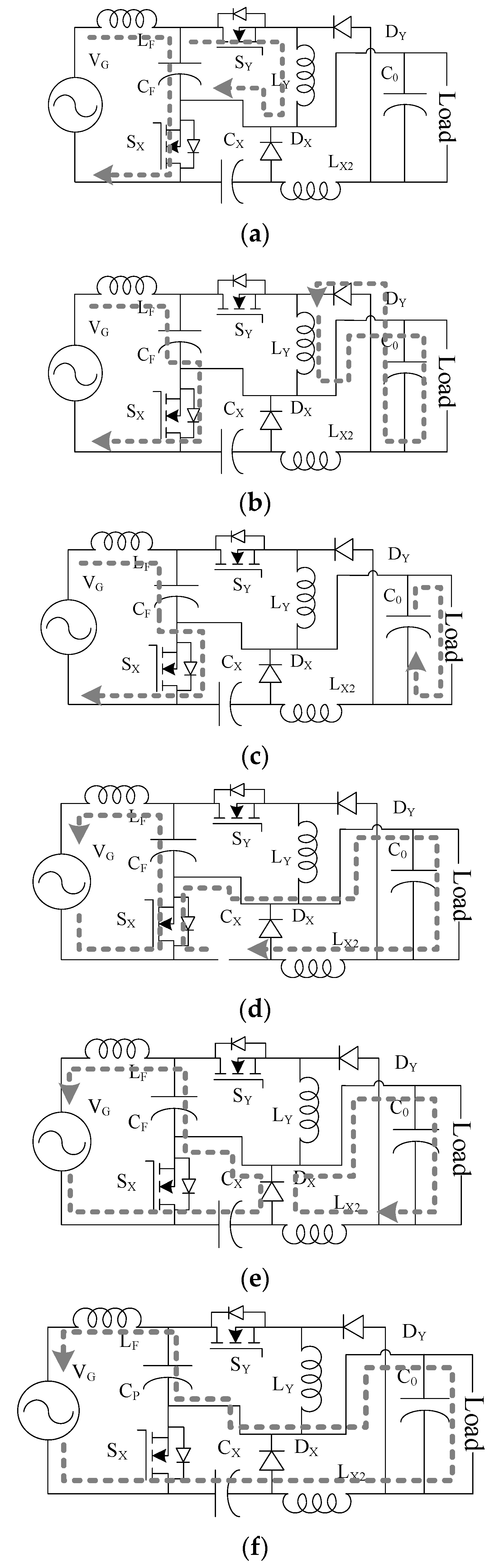
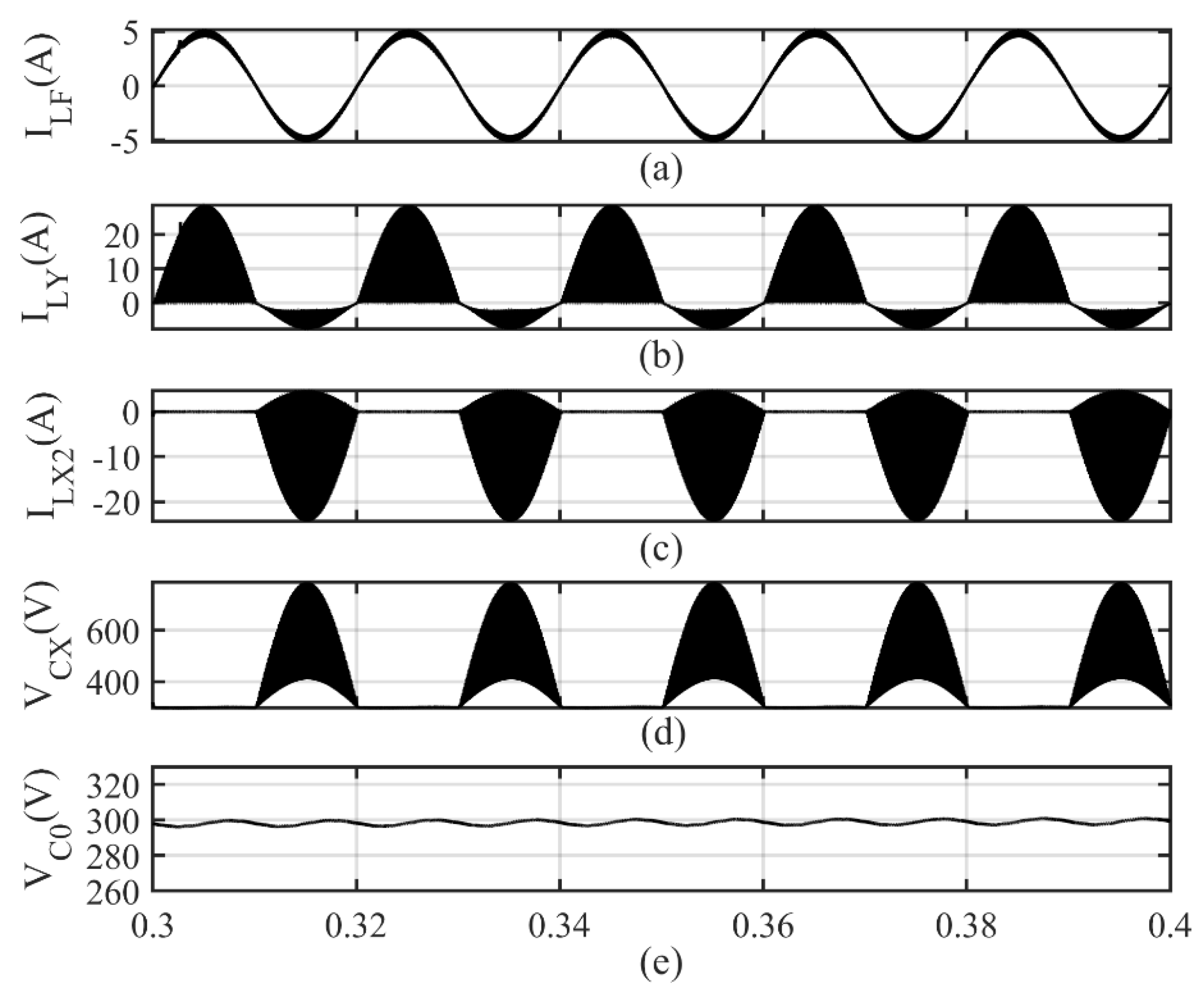
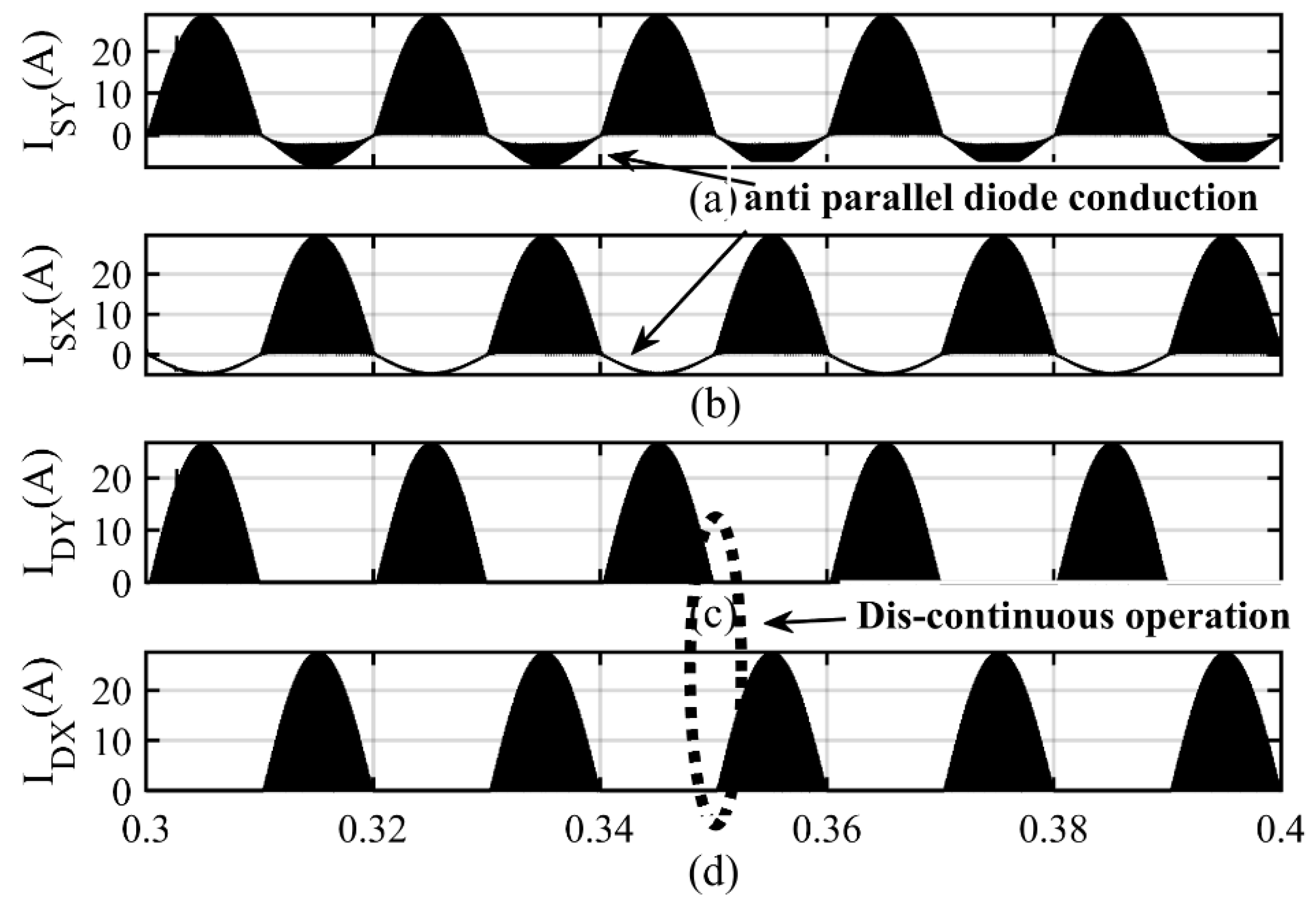
Mode I—The start of the positive semi-cycle of the main voltage initiates Mode I. IGBT SP is provided with a gate pulse throughout this time period. In addition, CF–LF–VG–CF and CF–SY–LY–CF are the conduction networks for this mode. The built-in anti-parallel IGBT (SY) diode additionally conducts during Mode I to complete the loop. In Figure 2a, a Mode I conduction path is deployed.
The following relationship is utilized for determining the inductor current:
V L = Ldi L dt
The maximum flow of the current through an IGBT SY operating in Mode I can be calculated as:
i SY _ peak = V CY d 1 T s L F
where TS stands for time interval and d1 for the duty cycle.
(2)
Mode II—IGBT SP is removed with an input gate pulse in Mode II. In Figure 2b, Mode II conduction loops are shown. The inductor LY discharges in Mode II via the load and diode DY. The formula can be used to calculate the diode current, which is:
i DY _ peak = V C 0 d 1 T s L Y
(3)
Mode III—The third and final mode of the positive semi-cycle is called DiCM. In Figure 2c, Mode III conduction loops are deployed. When the inductor’s energy storage is depleted, ModeVI begins.
(4)
Mode IV—IGBT SN is delivered with a gate signal in Mode IV. VG–SX–CF–LF–VG and SX–C0||R–LX2–CX–SX comprise the Mode IV conduction network. Capacitor CX is discharged through a load in this operating state. For greater clarity, the Mode IV loops have been deployed in Figure 2d. The following are the values for the maximum IGBT SX current stress in Mode IV:
i SX _ peak = i LF + i LX 2
where,
i LF = ( V G V CF ) d 1 T s L F
i LX 2 = ( V C 0 V CX ) d 1 T s L X 2
(5)
Mode V—Switch SX is disabled in Mode V, and Figure 2e shows the deployment of this mode’s conduction loop. In Mode V, Capacitor CX charging takes place, and the Diode DX conduction is observed throughout this time. The loop in Mode V is LF–CX–DX–CF–VG–LF. A DC-link capacitor (C0), in parallel with the load, is an additional loop constructed using an inductor LX2 and a diode DX. The maximum diode current via diode DN can be calculated using the equation.
i DX _ peak = ( V C 0 ) d 2 T s L X 2 + { V G ( V CX + V CF ) } d 2 T s L F
where, d 2 = Mode   V   duration   T S .
The peak voltage across switch SX is determined as follows:
V SX _ peak = V CX 2
(6)
Mode VI—In this mode, the IGBT SX is still not conducting. This mode begins as soon as Diode DX ceases to operate, causing the identical current to flow via Capacitor CX and Inductor LX2. When the supply voltage is in its negative semi-cycle, Mode VI is also known as the DICM mode. In Figure 2f, the conducting network is established during Mode VI.
The mathematical formula for the DCM mode is— d 1 T s + d 2 T s < T s .
Where, dON = dN and dOFF = dP + dDICM.
In addition,
d 1 + d 2 + d DICM = 1

2.2. Distinctive Features of PFA Converter

The power-factor augmentation, reduced element count, improved performance, easier control, eviction of the rectifier, reverse-feeding diode eviction, and presence of load-terminal inductances (LX2 and LY) to improve the load current profile over positive (+ve) as well as negative (−ve) semi-cycles of main voltages are the distinguishing characteristics of the PFA converter. Table 1, which is shown below, compares various bridgeless (BL) converter schemes and provides total element counts across different configurations, as well as the number of inductors, capacitors, switches, diodes, and transformers employed in the drive.

2.3. MPP Converter Operation

For MPP purposes, this work uses a boost converter, which not only performs as an MPP function but also increases the voltage by multiplying the grid voltage with a fraction of (1/(1 − dPV). The boost converter is a second-order converter with supply terminal inductance. The challenge with the MPP boost converter is to carefully analyze whether the maximum power for the solar array falls in the operating zone of the MPP boost converter. The buck and boost converters do not have a complete first quadrant available for operation unlike buck-boost converters. Therefore, the designer should check with the help of the power curve and I–V plot that the maximum power is within the range of operation of the converter. Otherwise, the MPP algo will not be able to track maximum power. The circuit of MPP converter is shown in Figure 1, and its MPP algo is discussed in later section.

2.4. Selection of PFA Converter Components

The system uses an asymmetrical converter for PFA, which requires a careful analysis to calculate the value of inductance and capacitance so that the main current during both half cycles of grid voltage are similar in shape and magnitude. The complete disappearance of the diode current (IDX) signals the start of the PFA converter’s DICM operation during the negative semi-cycle of the main voltage. The inductor LX2 current in this situation crosses the zero line and turns positive with an output magnitude equivalent to the capacitor CY current. Nevertheless, after the full power drain of the inductor LF, the positive semi-cycle DICM operation begins. For DICM mode operation, it is essential to select an inductor LF value that ensures the inductor discharges entirely before its positive main voltage semi-cycle was finished. However, the capacitor voltages VCY and VCX are constant during the cycle. The BLDC motor specifications under the test are in the Appendix A. The driver’s typical main voltage may be found with the relation
V G _ AVG = ( 2 2 ) π × V G = 0.901 × 220 = 198.10
The V-sec (voltage-second) equilibrium among the inductors of the PFA converter can be used to determine the output terminal and input main ratio of the PFA converter for both cycles.
V C 0 V G = d 1 1 d 1
The average input main voltage and the voltage over the DC-link capacitor appear to be important influences on the duty cycle of the PFA converter.
d A = V C 0 V G _ AVG + V C 0 = 300 198.10 + 300 = 0.6010
Losses and inductor size are switching frequency and inductance values. The dimensions and amplitude of the inductor grow as the switching frequency lowers. Furthermore, a lower degree of inductance has a linked issue of increasing current stress in DICM mode operating of the PFA converter because solid-state devices (switches) experience increased switching losses at greater switching frequencies. Although switching losses are significantly reduced with a lower switching frequency, the cost, dimensions, and magnitude of the inductor all increase. Therefore, considering the aforementioned factors, 20 kHz is chosen as the switching frequency for the current job. The relation evaluates the critical input inductance, LF, for the PFA converter.
L F = V G _ AVG   ×   d 1 2 Δ I G f s = V IN _ AVG d 1 2 Δ ( P V G _ AVG ) f s = 198.10   ×   0.301 2   ×   0.1   ×   ( 850 / 198.10 )   ×   20   ×   1000 = 3.475   mH
The value should be greater than the computed critical value as the input inductor must function in the CCM mode. The chosen value of LF for the current task is 4.5 mH.
Equations can be used to obtain output inductances for semi-cycles LX2 and LY.
L Y , X 2 = V 0 ( 1 d 1 ) Δ I 0 f s = 300 × ( 1 0.301 ) 0.2 × ( 850 ÷ 300 ) × 20 × 1000 = 9.26   mH
For the discontinuous operation of the PFA converter, the output inductor must be operated in DICM mode since its current polarity fluctuates. For this study, the 20th part of the estimated valve, or 0.196 mH, was chosen. With the following formula, the numerical value of the capacitor CX can be determined.
C X = I LX 1 d 1 Δ V CX f s = ( 850 ÷ 198.10 ) × 0.301 0.4 × ( 300 + 198.10 ) × 20 × 1000 = 0.32   μ F
The value selected for capacitor CX must be higher than the computed critical value in order for it to function in CCM. Therefore, CX is set to 0.5 F for the purposes of this investigation.
The formula can be used to determine the filter-capacitor magnitude for the converter running in the positive grid voltage cycle
C F = 1 4 π 2 f c 2 L F = 1 4 π 2 × 3800 2 × 4 . 5 × 10 3 = 431   nF
For the current work, a cutoff frequency of 3.8 kHz has been picked since the cutoff frequency in the computation of the filter capacitance ought to fall between switching and line frequency.
Rearranging the power equation will allow you to determine the value of the DC-link capacitor (C0).
P Max = V Max sin { ( 2 π × f L ) t } × I Max sin { ( 2 π × f L ) t }
P Max = 2 V Max I Max sin 2 { ( 2 π × f L ) t } = V Max I Max { 1 cos 2 ( 2 π × f L ) t }
The following formula might be rewritten as follows since the DC–Link capacitor manages the second harmonic portion
V C 0 × i C 0 = V Max I Max cos { 2 ( 2 π × f L ) t }
C 0 = i C 0 2 ( 2 π × f L ) Δ V 0 = P V 0 × 1 4 π f L Δ V 0
where ΔV0 is the allowed voltage ripple across the DC-link capacitor. Equation (17) can be used to compute the value of the DC link capacitance C0.
C 0 = P V 0 × 1 2 ( 2 π   ×   f L ) Δ V 0 C 0 = 850 198 . 10 × 1 4 π   ×   50   ×   0 . 02   ×   198 . 10 = 1 . 726 mF
Therefore, a 1.8-mF capacitor is selected for the DC link. The capacitor needs to be utilized at a lower switching (line) frequency because of the impact of second harmonics. The capacitor ought to have a larger capacitance value and a comparatively greater current rating. Since the capacitor itself must also have a higher capacitance value per unit volume, electrolytic capacitors might be appropriate for this application.

2.5. Selection of MPP Converter Components

The value of the photovoltaic array-based system, along with components, are listed in Table 2.

3. PFA Power-Factor Profile Improvement Converter-Based BLDC Speed Control

The control technique for the BLDC drive-fed by the PFA and MPP converter is described in this section. The complete BLDC drive design employs two different control loops: one to regulate the PFA converter output terminal voltage and the other for the MPP converter.

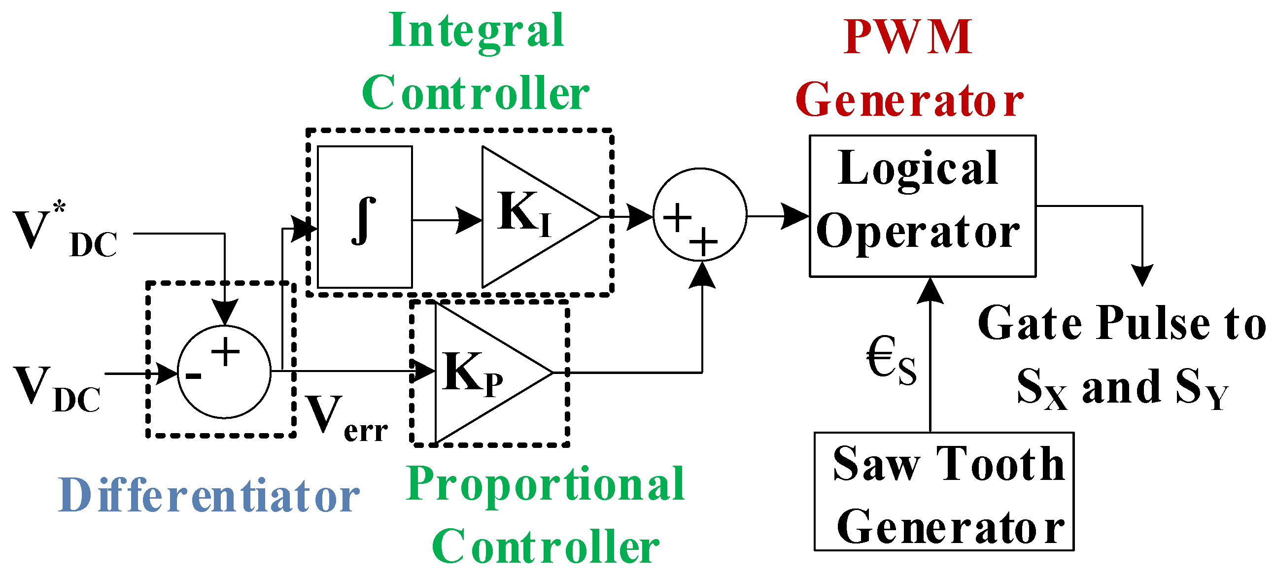
3.1. PFA Converter Control Scheme

In this paper, the operation of a DICM employing a PFA converter to optimize the power-factor profile is conducted using a voltage-tracking method. Unlike CCM, which requires two voltage sensors and one current sensor, this control has to sense dc-link voltage, which just requires a single-voltage sensor. The schematic representation of the control loop for the DC-link capacitor voltage is shown in Figure 3. This control strategy makes use of the saw-tooth wave generator, the proportional-integral (P–I) controller, the subtractor (error generator), and the pulse-width-modulation (PWM) generator unit.
Both the real (sensed) DC-link voltage and the referring DC-link voltage V0* are provided to the subtractor. The difference signal, which is the result of the subtractor, can be stated at the φth instant as below
V err ( φ ) = V 0 * ( φ ) V 0 ( φ )
The P–I controller receives a difference signal so as to generate a constant output voltage (V0). In order to express the controller output voltage, VCT,
V CT ( φ ) = V CT ( φ 1 ) + K I { V err ( φ ) } + K P { V err ( φ ) V err ( φ 1 ) }
where KP is proportional. However, KI is the integral constant values of the P–I controller. For the controlled voltage (VCT), when sent via a relational operator, a high-frequency saw-tooth wave (€S) generates a gate signal for the switches SY and SX. For gate-pulse generation, two cases exists depending upon the polarity of grid voltage. For both these cases, the gate pulse is generated only when €S is less than the controlled voltage. The insulated gate bipolar transistor (IGBT) only conducts whenever the gate pulse is available. An extra advantage of using the PFA bridgeless converter is the requirement of the same gate pulse (without any modification or phase delay) for both the IGBTs.

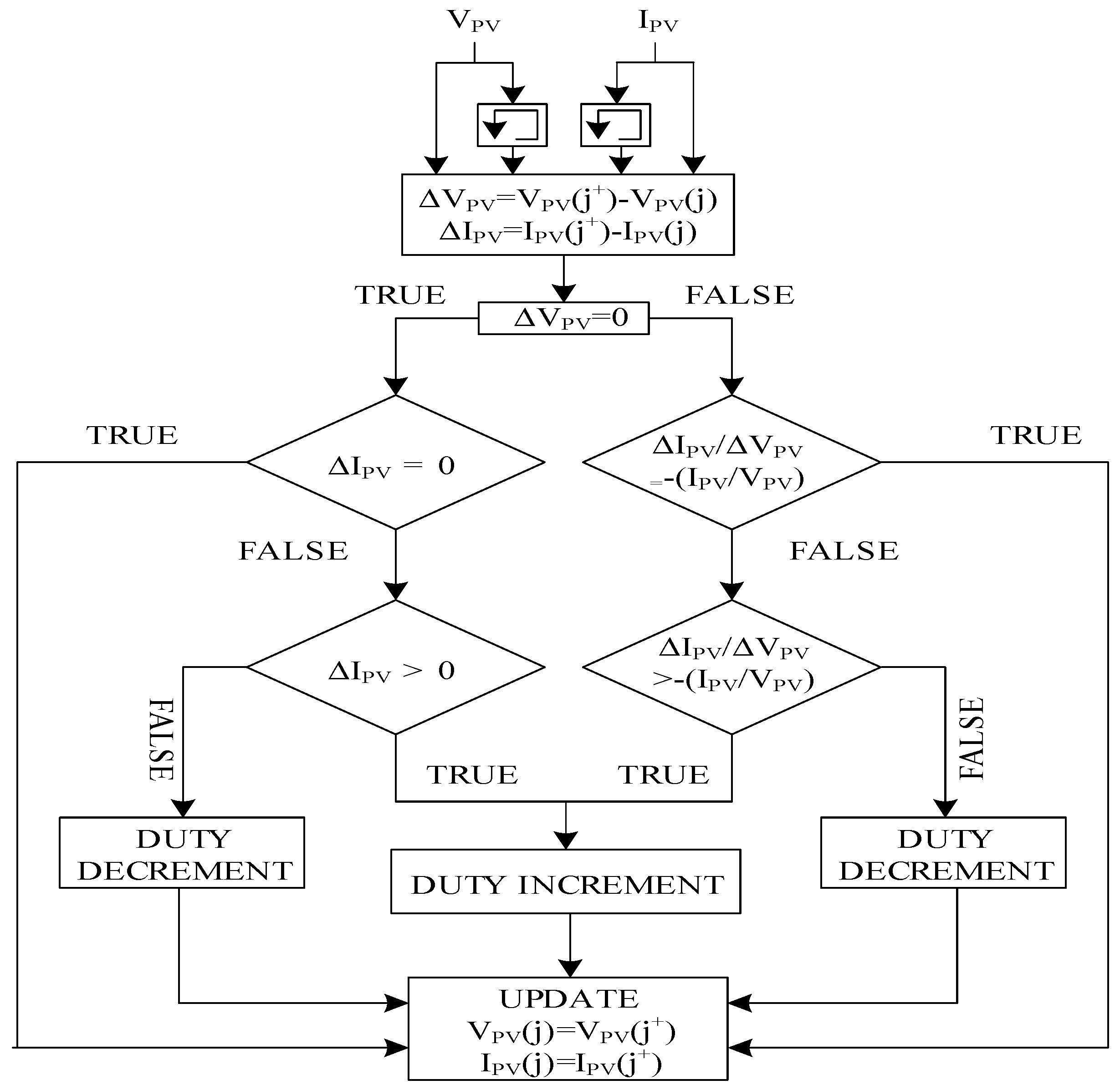
3.2. MPP Converter Control Technique

The gate pulse of the MPP follower converter is produced by using the INC technique. In this research, the solar PV voltage and current are applied to the MPP follower block, which provides the duty as the outcome. This outcome is applied to the PWM unit where it is compared and processed through the relational operator with the outcome of the high-frequency wave-generator unit. The outcome of this relational unit is the required gate pulse for the MPP boost converter. The logic diagram for the INC method used is shown in Figure 4.

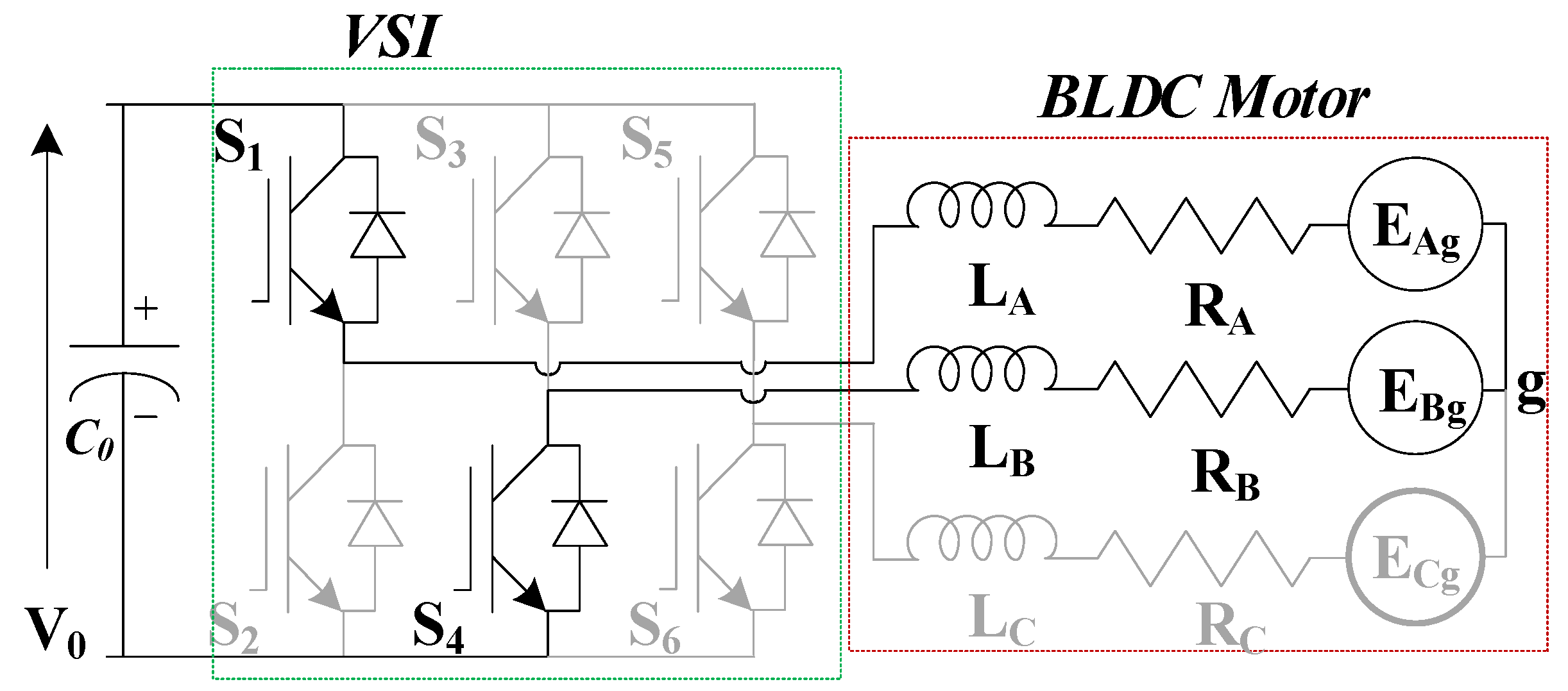
3.3. BLDC Motor Control

The electronic commutation method (ECM) is used to manage the speed of the BLDC motor, fully eliminating problems with maintenance, sparking, noise, and EMI while also greatly reducing the influence of the EMI. The hall-effect position sensors monitor the position of the BLDC motor rotor. Only two phases of the stator are allowed with excitation at any particular moment in the BLDC motor. Various VSI switches toggle on or off based on the rotor positioning (information provided by hall location sensors). This real-time rotor position information makes it possible to control the direction of current flow in the BLDC motor’s various windings at various times. When the VSI switches S1 and S4 conducts, Figure 5 depicts the durational conducting path. At this moment, the path depicted in Figure 5 is followed by applying the DC link voltage across the BLDC motor. Therefore, the amplitude and direction of the current are both influenced by the back EMFs (EAg and EBg), the DC-link voltage V0, the self- and mutual-inductances of the windings (A and B), and the mutual inductance (MAB). Additionally, Table 3 displays the switching states of all six VSI switches based on data from three Hall sensors (Ha, Hb, and Hc) feeding the BLDC motor.

4. Validation and Result

This section examines the performance of the PFA converter-based dual-source driver using MATLAB/Simulink results during all three conditions discussed above. The section also studies the PFA operation of the BLDC motor drive during the dynamic, as well as the steady condition when only the grid is the present source for energy.

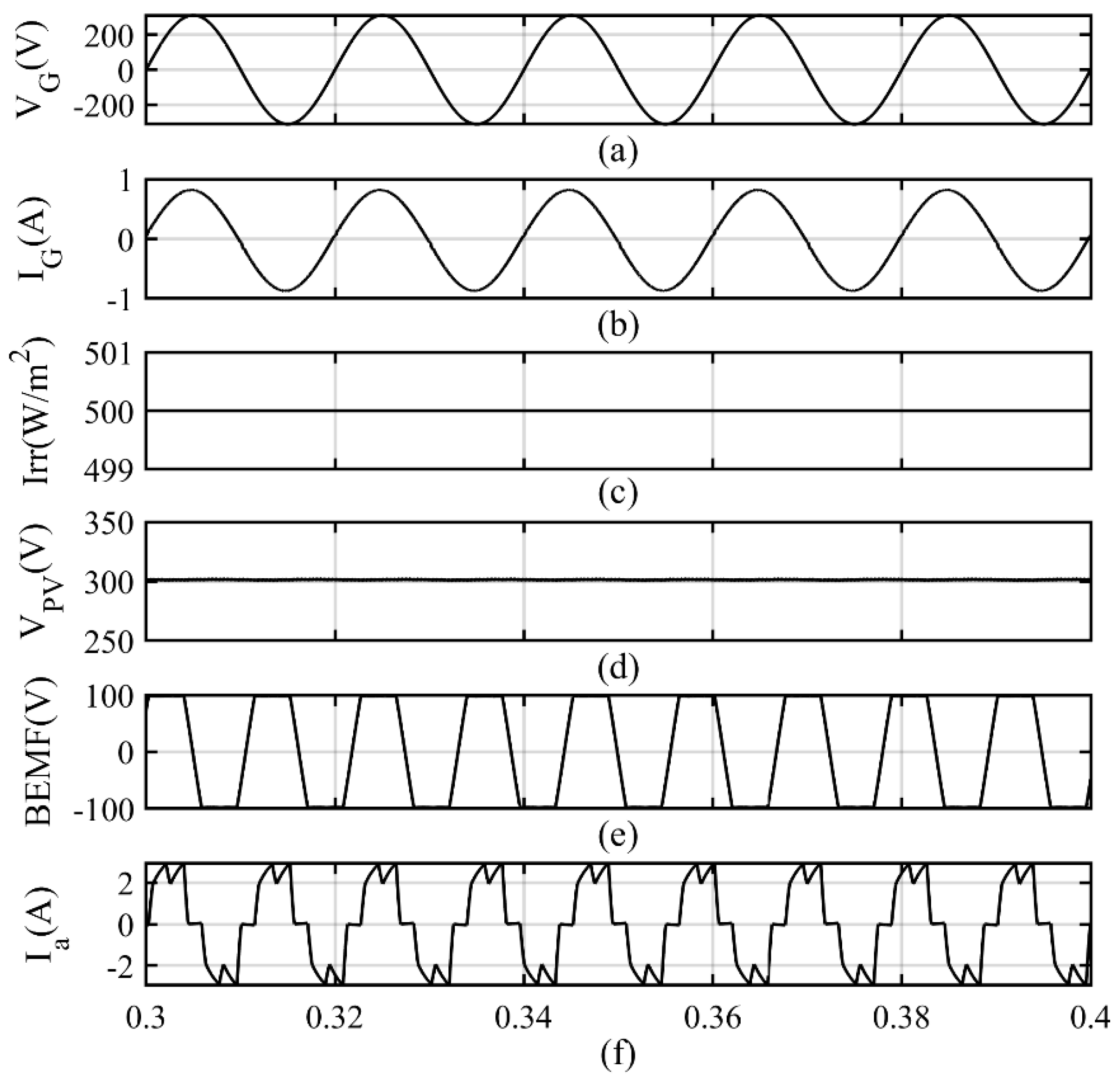
4.1. BLDC Motor Drive Performance during First Case (Both Sources Are Present)

This case represents the condition when both the sources are present with the power requirement at the load is less than or equal to power generated at PV array. During this condition, the load is fed by the solar-generated energy. When the solar array power is less than the load then both the grid and solar array will both feed the load. The condition when solar-array generation is more than the load demand then the results shown in Figure 6. The results in Figure 6a,b show the solar irradiance and voltage across the solar array. The trapezoidal back emf and armature current can be seen in Figure 6c,d. The results for the condition, when the solar-array generation is not zero but less than the load demand, is shown in Figure 7. To reduce the solar generation, the irradiance is reduced to 500 W/m2 at a fixed temperature of 25 °C. The linearly related grid voltage and current can be seen in Figure 7a,b. The solar irradiance and array voltage can be seen in Figure 7c,d. The trapezoidal back emf and BLDC motor armature current can be seen in Figure 7e,f, respectively.

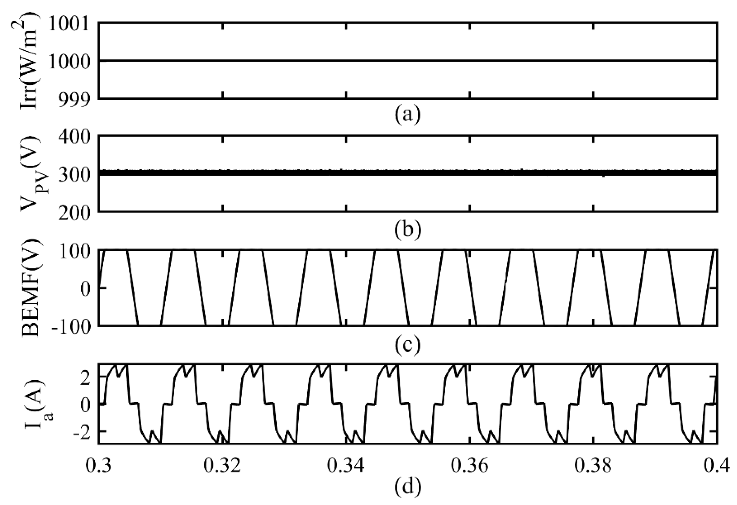
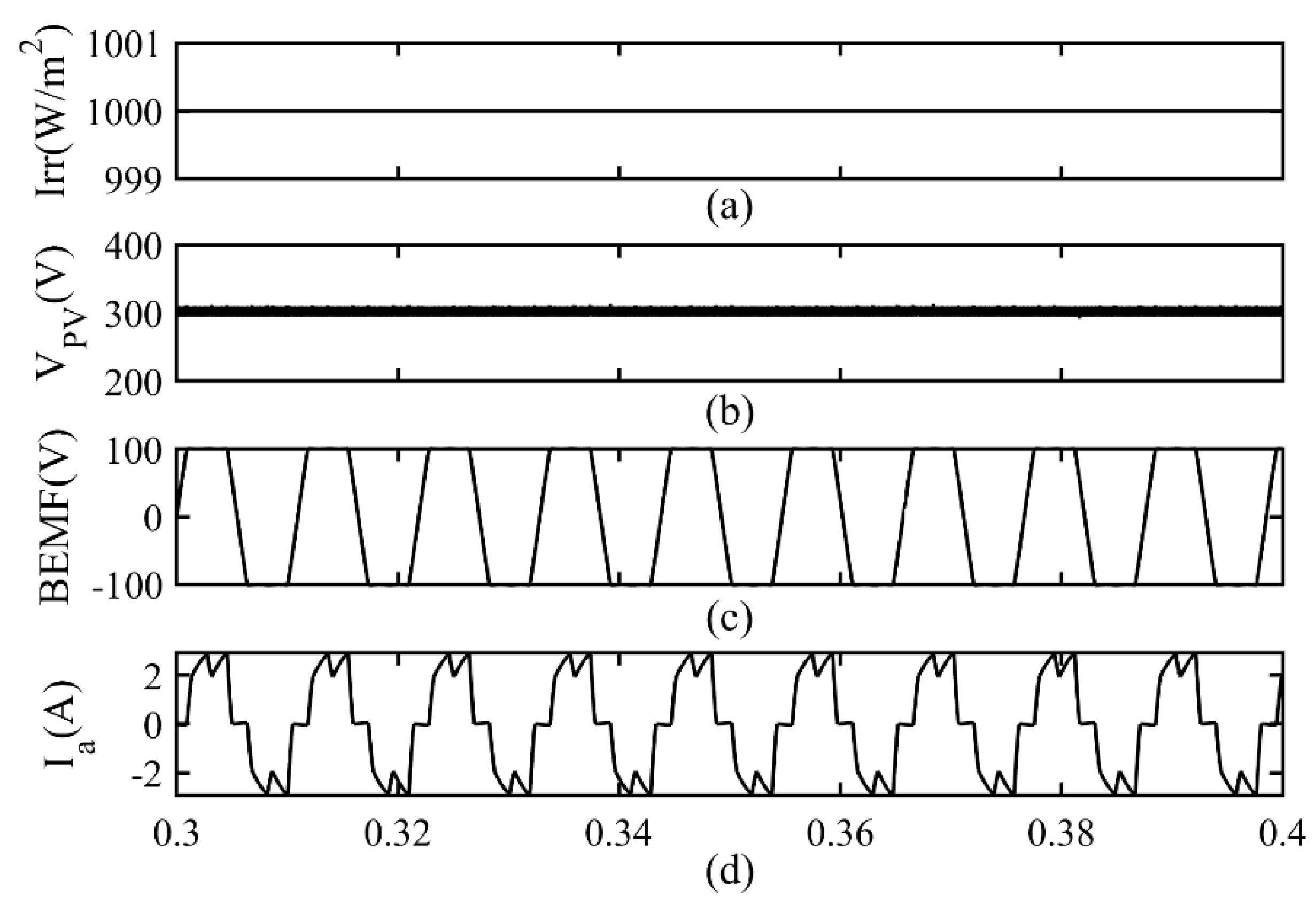
4.2. BLDC Motor Drive Performance during Second Case (Only Solar Energy Source Is Present)

This section examines the drive performance when solar energy is the only available source. The simulation results for this case are shown in Figure 8. The solar irradiance and array voltage with motor parameters can be seen in Figure 8.

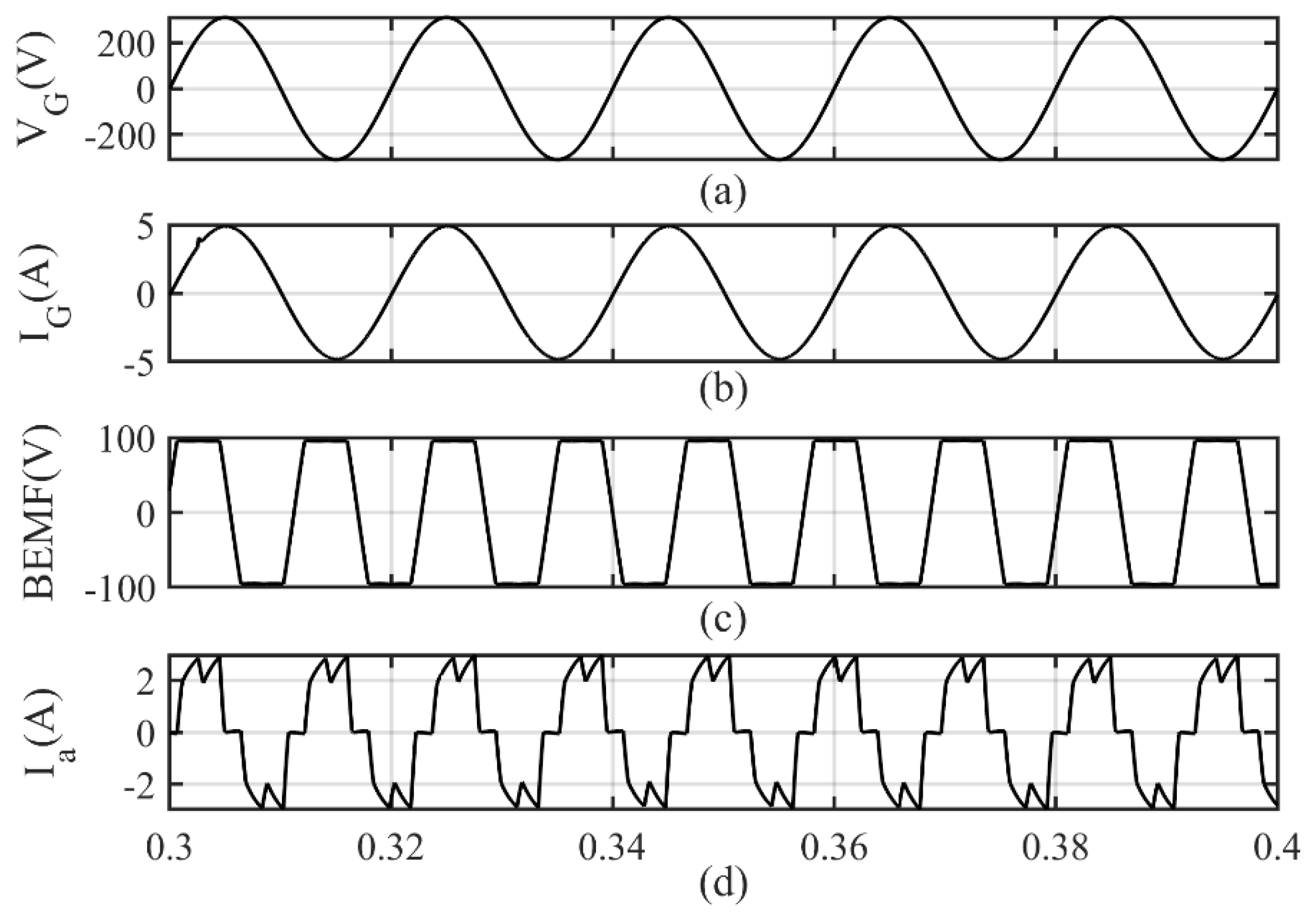
4.3. BLDC Motor Drive Performance during Third Case (Only Grid Is Present)

This section examines the PFA converter-based BLDC motor-driver performance when only the grid is the active source. Figure 9 verifies the power-factor correction operation of the PFA converter as the voltage profile is exactly being followed by the grid current. The BLDC motor back emf and armature current are shown in Figure 9c,d.
The current and voltage across different components of the PFA converter are shown in Figure 10. The inductor current across Inductors LF, LY, and LX2 are shown in Figure 10a–c, respectively. The capacitor voltage across the capacitor CX and C0 are deployed in Figure 10d,e. The current across Switches SY and SX, as well as Diodes DY and DX, are shown in Figure 11a–d. The discontinuous operation of the diode current before semicycle completion witnesses the discontinuous mode operation.

5. Conclusions

The performance of the brushless DC motor pump is examined in this article in all three scenarios: first, when the grid and solar energy are both present; second, when the solar energy is the only source of energy; and third, when the grid energy is the only source of energy. The motor performance in all three conditions is found satisfactory with almost no power drawn from the grid when the solar energy is present. In addition, the input current and voltage from the grid in the third case are found to be in phase and share a linear relationship with each other. The grid-current distortion is found to be less than 5% satisfying of the IEC standard limits. The elements of the PFA converter with different power-quality-improvement converters have been compared, and the PFA converter with a lesser number of elements was found to be working satisfactory.

Author Contributions

Methodology, T.S.; Validation, T.S. and S.N.; Formal analysis, T.S.; Investigation, T.S.; Data curation, T.S. and S.N.; Writing–original draft, T.S.; Writing–review & editing, T.S. and S.N.; Supervision, S.N. All authors have read and agreed to the published version of the manuscript.

Funding

No funding has been received for this work.

Data Availability Statement

Data sharing not applicable.

Conflicts of Interest

The authors declare no conflict of interest.

Appendix A

Quad-pole, Rated Power (PR) = 850 W, Rated Voltage at DC-Link (VR) = 300 V, Rated Torque (TR) = 1.46 Nm, Rated-Speed (ω*) = 2000 rpm, Phase-Inductance (Lph) = 26.21 mH, Phase-Resistance (Rph) = 14.42 Ω, J (Moment of Inertia) = 1.26 × 10⁻⁴ m/s2.

References

  1. Khan, M.T.A.; Norris, G.; Chattopadhyay, R.; Husain, I.; Bhattacharya, S. Autoinspection and permitting with a PV utility interface (PUI) for residential plug-and-play solar photovoltaic unit. IEEE Trans. Ind. Appl. 2017, 53, 1337–1346. [Google Scholar] [CrossRef]
  2. Montorfano, M.; Sbarbaro, D.; Morán, L. Economic and technical evaluation of solar-assisted water pump stations for mining applications: A case of study. IEEE Trans. Ind. Appl. 2016, 52, 4454–4459. [Google Scholar] [CrossRef]
  3. Talbi, B.; Krim, F.; Rekioua, T.; Mekhilef, S.; Laib, A.; Belaout, A. A high-performance control scheme for photovoltaic pumping system under sudden irradiance and load changes. Sol. Energy 2018, 159, 353–368. [Google Scholar] [CrossRef]
  4. Periasamy, P.; Jain, N.; Singh, I. A review on development of photovoltaic water pumping system. Renew. Sustain. Energy Rev. 2015, 43, 918–925. [Google Scholar] [CrossRef]
  5. Kumar, R.; Singh, B. BLDC motor driven solar PV array fed water pumping system employing zeta converter. IEEE Trans. Ind. Appl. 2016, 52, 2315–2322. [Google Scholar] [CrossRef]
  6. Singh, B.; Kumar, R. Solar PV array fed water pump driven by BLDC motor using landsman converter. IET Renew. Power Gener. 2016, 10, 474–484. [Google Scholar] [CrossRef]
  7. Rahrah, K.; Rekioua, D.; Rekioua, T.; Bacha, S. Photovoltaic pumping system in Bejaia climate with battery storage. Int. J. Hydrogen Energy 2015, 40, 13665–13675. [Google Scholar] [CrossRef]
  8. Khiareddine, A.; Ben Salah, C.; Mimouni, M.F. Power management of a photovoltaic/battery pumping system in agricultural experiment station. Sol. Energy 2015, 112, 319–338. [Google Scholar] [CrossRef]
  9. Sigarchian, S.G.; Malmquist, A.; Fransson, T. Modeling and Control Strategy of a Hybrid PV/Wind/Engine/Battery System to Provide Electricity and Drinkable Water for Remote Applications. Energy Procedia 2014, 57, 1401–1410. [Google Scholar] [CrossRef]
  10. Khiareddine, A.; Ben Salah, C.; Mimouni, M.F. Strategy of Energy Control in PVP/Battery Water Pumping System. In Proceedings of the 2014 First International Conference on Green Energy ICGE 2014, Sfax, Tunisia, 25–27 March 2014; pp. 49–54. [Google Scholar] [CrossRef]
  11. Ugale, J.H.; Panse, M. Single Phase AC Drive for Isolated Solar Photovoltaic Water Pumping System. In Proceedings of the 2015 International Conference on Green Computing and Internet of Things (ICGCIoT), Greater Noida, India, 8–10 October 2015; pp. 1285–1287. [Google Scholar] [CrossRef]
  12. Boussaibo, A.; Kamta, M.; Kayem, J.; Toader, D.; Haragus, S.; Maghet, A. Characterization of Photovoltaic Pumping System Model without Battery Storage by MATLAB/Simulink. In Proceedings of the 2015 9th International Symposium on Advanced Topics in Electrical Engineering (ATEE), Bucharest, Romania, 7–9 May 2015; pp. 774–780. [Google Scholar] [CrossRef]
  13. Yan, Z. Photovoltaic Pumping System Using Power Grid as Energy Storage Device. Chinese Patent CN 202455296 U, 26 September 2012. [Google Scholar]
  14. Huang, M. Photovoltaic Water Pumping and Residual Electricity Gridconnected System. Chinese Patent CN 204131142 U, 28 January 2015. [Google Scholar]
  15. Xing, W. High-Efficiency Photovoltaic Pump System. Chinese Patent CN 203884338 U, 22 October 2014. [Google Scholar]
  16. Steel, C.; Fang, A.; Weilong, S.; Jing, G.; Xiong, Z. Photovoltaic Agricultural Power Generating Unit. Chinese Patent CN 203859717 U, 1 October 2014. [Google Scholar]
  17. Qiang, L.T. Solar Power Station with Water Pumping and Energy Storage. Chinese Patent CN 103595337 A, 19 February 2014. [Google Scholar]
  18. Shukla, T.; Nikolovski, S. A Bridgeless Cuk-BB-Converter-Based BLDCM Drive for MEV Applications. Energies 2023, 16, 3747. [Google Scholar] [CrossRef]
  19. Shukla, T.; Kalla, U.K. A BL-CC Converter-Based BLDC Motor Drive for Marine Electric Vehicle Applications. Int. Trans. Electr. Energy Syst. 2022, 2022, 7026462. [Google Scholar] [CrossRef]
  20. IEC 61000-3-2; Limits for Harmonics Current Emissions (Equipment Current per Phase). International Electrotechnical Commission: Geneva, Switzerland, 2000.
  21. El Khateb, A.; Rahim, N.A.; Selvaraj, J.; Uddin, M.N. Fuzzy-logiccontroller-based SEPIC converter for maximum power point tracking. IEEE Trans. Ind. Appl. 2014, 50, 2349–2358. [Google Scholar] [CrossRef]
  22. Singh, B.; Bist, V.; Chandra, A.; Al-Haddad, K. Power Factor Correction in Bridgeless-Luo Converter-Fed BLDC Motor Drive. IEEE Trans. Ind. Appl. 2015, 51, 1179–1188. [Google Scholar] [CrossRef]
  23. Singh, B.; Bist, V. A BL-CSC Converter-Fed BLDC Motor Drive with Power Factor Correction. IEEE Trans. Ind. Electron. 2015, 62, 172–183. [Google Scholar] [CrossRef]
  24. Bist, V.; Singh, B. A Unity Power Factor Bridgeless Isolated Cuk Converter-Fed Brushless DC Motor Drive. IEEE Trans. Ind. Electron. 2014, 62, 4118–4129. [Google Scholar] [CrossRef]
  25. Kumar, P.; Mishra, S. Bridgeless Landsman Converter Based PM-BLDC Motor Drive for Exhaust Fan. In Proceedings of the 2022 2nd International Conference on Intelligent Technologies (CONIT), Hubli, India, 24–26 June 2022; pp. 1–7. [Google Scholar] [CrossRef]
  26. Jayachandran, S.; Pavana; Vinatha, U. One Cycle Controlled Bridge-Less SEPIC Converter fed BLDC Motor Drive. In Proceedings of the 2017 IEEE International Conference on Signal Processing, Informatics, Communication and Energy Systems (SPICES), Kollam, India, 8–10 August 2017; pp. 1–6. [Google Scholar] [CrossRef]
  27. Ramya, A.; Balaji, M.; Bharatiraja, C. Power Quality Improvement in BLDC Motor Drive using Bridgeless Modified Cuk Converter. In Proceedings of the 2018 IEEE International Conference on Power Electronics, Drives and Energy Systems (PEDES), Chennai, India, 18–21 December 2018; pp. 1–6. [Google Scholar] [CrossRef]
  28. Singh, B.; Bist, V.; Chandra, A.; Al-Haddad, K. Power Quality Improvement in PFC Bridgeless-Luo Converter fed BLDC Motor Drive. In Proceedings of the 2013 IEEE Industry Applications Society Annual Meeting, Lake Buena Vista, FL, USA, 6–11 October 2013; pp. 1–8. [Google Scholar] [CrossRef]
  29. Saha, B.; Singh, B.; Sen, A. SMO Based Position Sensorless BLDC Motor Drive Employing Canonical Switching Cell Converter for Light Electric Vehicle. IEEE Trans. Ind. Appl. 2023, 59, 2974–2984. [Google Scholar] [CrossRef]
  30. Umapathi, K.; Kathiravan, G.; Usha, P. Design and Development of INC-MPPT Switched ZETA Converter for Solar PV Arrays. In Proceedings of the 2023 9th International Conference on Advanced Computing and Communication Systems (ICACCS), Coimbatore, India, 6–7 June 2023; pp. 1434–1438. [Google Scholar] [CrossRef]
  31. Padhi, R.; Behera, B.P.; Mohanty, K.B.; Daramukala, P. Integrated SPV-Battery BLDC Motor Drive Powered by Interleaved Boost Converter. In Proceedings of the 2023 International Conference on Power, Instrumentation, Energy and Control (PIECON), Aligarh, India, 10–12 February 2023; pp. 1–6. [Google Scholar] [CrossRef]
Figure 1. PV array and grid source-fed BLDC motor drive.
Energies 16 06133 g001
Figure 2. PFA converter working during (a) Mode I; (b) Mode II; (c) Positive semi-cycle DICM mode; (d) Mode IV; (e) Mode V; (f) Negative semi-cycle DICM mode. The grey lines shows the conduction path during different modes.
Energies 16 06133 g002
Figure 3. PFA converter control method.
Energies 16 06133 g003
Figure 4. INC logic flowchart.
Energies 16 06133 g004
Figure 5. BLDC motor fed by VSI with switch S1 and S4 in “ON” state.
Energies 16 06133 g005
Figure 6. BLDC motor and its drive performance during Case 1 when solar energy is more than demand: (a) Solar irradiance; (b) Voltage across PV array; (c) Back emf of BLDC motor; (d) Armature current.
Energies 16 06133 g006
Figure 7. Motor and its drive performance during Case 1 when solar energy is less than load demand: (a) Grid voltage; (b) Grid current; (c) Solar irradiance; (d) Voltage across PV array; (e) Back emf of BLDC motor; (f) Armature current.
Energies 16 06133 g007
Figure 8. BLDC motor and its drive performance during Case 2: (a) Solar irradiance; (b) Voltage across PV array; (c) Back emf of BLDC motor; (d) Armature current.
Energies 16 06133 g008
Figure 9. Performance of BLDC motor and its drive in third case: (a) Grid voltage; (b) Grid current; (c) BEMF; (d) Armature current.
Energies 16 06133 g009
Figure 10. Parameters of PFA converter: (a) Filter inductor current; (b) ILY; (c) Current through inductor LX2; (d) Voltage across capacitor CX; (e) VC0.
Energies 16 06133 g010
Figure 11. Current through PFA converter diodes and switches: (a) ISY; (b) ISX; (c) IDY; (d) IDX.
Energies 16 06133 g011
Table 1. Assessment of the described PFA AC–DC converter in comparison with different BL-configured converters for the objective of improving power factor.
S.No.TopologyComponents Count
SwitchXCLDTotal
01BL-Luo [22]20045416
02BL-CSC [23]20043413
03BL-isolated Cuk [24]20265419
04BL-Landsman [25]20045415
05BL-SEPIC [26]20045415
06BL-Zeta [28]20045415
07BL-Cuk [27]40032211
08Proposed PFA Converter20033210
Table 2. Solar PV array-based system.
Module1 Soltech 1STH-215-P
VOC36.30 V
ISC07.84 A
PMax213.15 W
Series module/string20
Parallel String11
CZ440 nF
LZ2.8 mH
C02.2 mF
Table 3. VSI Switching states for BLDC motor based on Hall sensor data.
θ
(Degree)
Hall Effect Sensor SignalsSwitching States of VSI
HaHbHcS1S2S3S4S5S6
(0–360/6)101100100
(360/6)–(360/3)100100001
(360/3)–(360/2)110001001
(360/2)–(360∗2/3)010011000
(360∗2/3)–(360∗5/6)011010010
(360∗5/6)–360001000110
NA000000000
Disclaimer/Publisher’s Note: The statements, opinions and data contained in all publications are solely those of the individual author(s) and contributor(s) and not of MDPI and/or the editor(s). MDPI and/or the editor(s) disclaim responsibility for any injury to people or property resulting from any ideas, methods, instructions or products referred to in the content.

