
Low-Temperature Fabrication of Flexible Dye-Sensitized Solar Cells: Influence of Electrolyte Solution on Performance under Solar and Indoor Illumination

Abstract
:1. Background and Context
2. DSSCs
3. Exploring the Essential Components and Operational Mechanism of DSSC
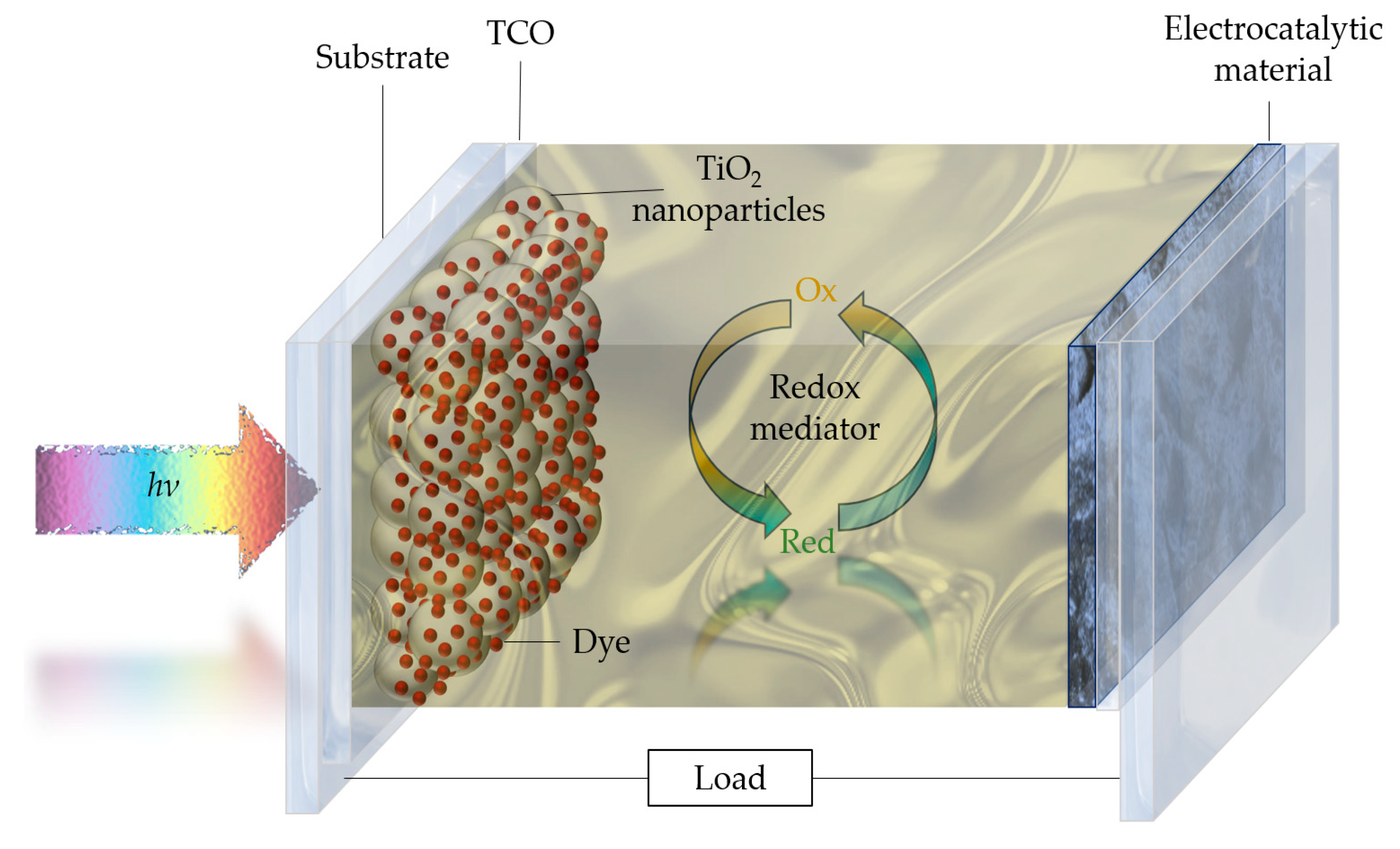
3.1. DSSC Elemental Structure
- The photoelectrode consists of a transparent conductive oxide coated substrate onto which a mesoporous oxide layer is deposited. This layer facilitates the transfer of electrons generated by the absorption of sunlight by the sensitizer.
- The sensitizer is a molecular monolayer of dye that is adsorbed onto the surface of the mesoporous oxide layer. Its function is to harvest incident sunlight and transfer electrons to the oxide.
- The electrolyte typically consists of an organic solvent that contains a redox mediator. This component is crucial for the regeneration of the dye and the redox electrolyte during operation.
- The counter electrode is typically a fluorine-doped tin oxide (FTO) or indium tin oxide (ITO) on glass or plastic coated with a catalyst material that facilitates the redox couple regeneration reaction and collects electrons from the external circuit (Figure 1).
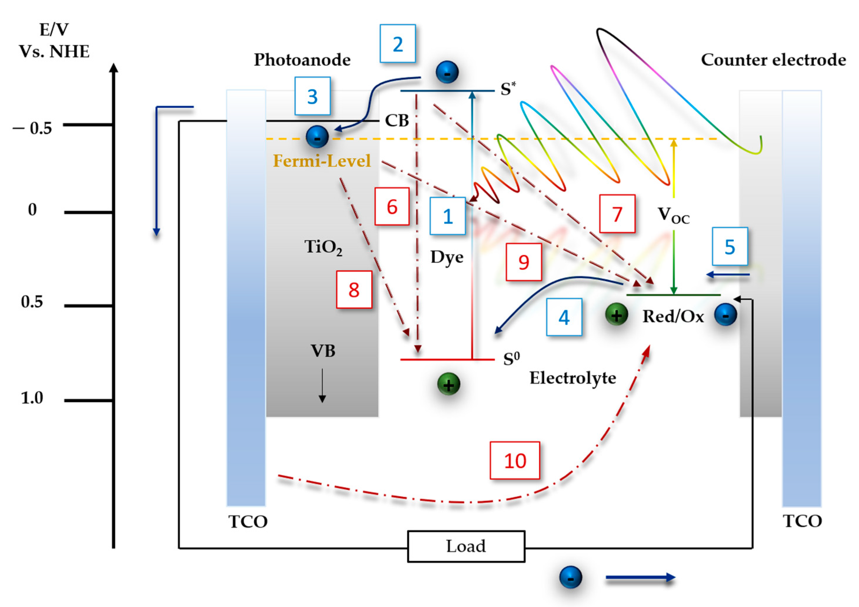
3.2. DSSC Operational Mechanism
3.3. Recombination Processes
3.4. DSSC PV Parameters
4. Flexible Photoelectrodes: Key Design Considerations for Optimal Performance
5. Mastering Flexibility: Pioneer and Cutting-Edge Strategies for Photoelectrode Manufacturing
5.1. Low-Temperature Physical-Chemical Binding
5.2. Film Transfer Techniques
5.3. TiO2 Film Compression
5.4. Low-Temperature Deposition Techniques
5.5. UV Irradiation Post-Treatment
5.6. Microwave Irradiation Post-Treatment
5.7. Accelerated Electron Beam (EB) Post-Treatment
5.8. Combination of Different Strategies
6. Experimental Section
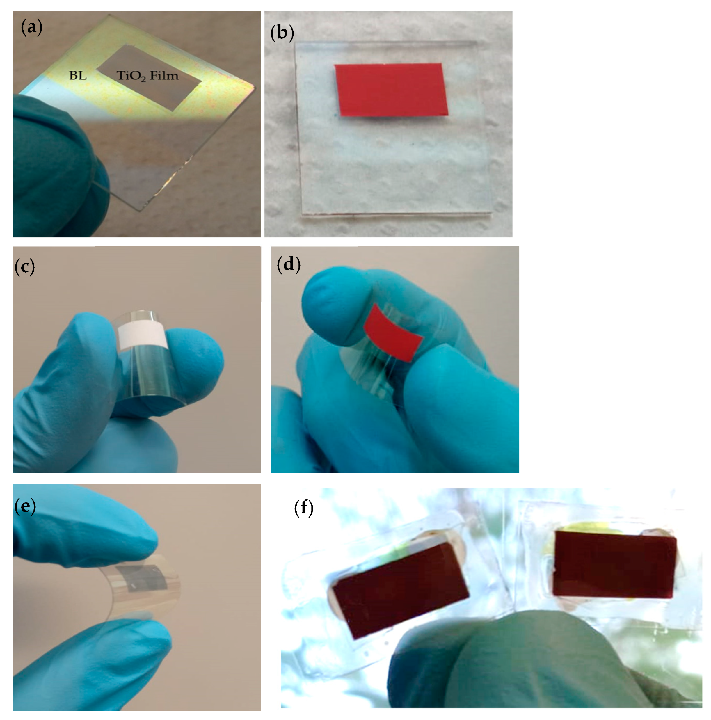
6.1. Rigid and Flexible Substrates Preparation
6.2. Low-Temperature Blocking Layer
6.3. TiO2 Nanoparticle Synthesis
6.4. Binder-Free Aqueous Paste for Low-Temperature Rigid and Flexible Dye-Sensitized TiO2 Films
6.5. Rigid and Flexible Counter Electrodes
6.6. Electrolyte Preparation
6.7. Rigid and F-DSSC Assembly
7. Results
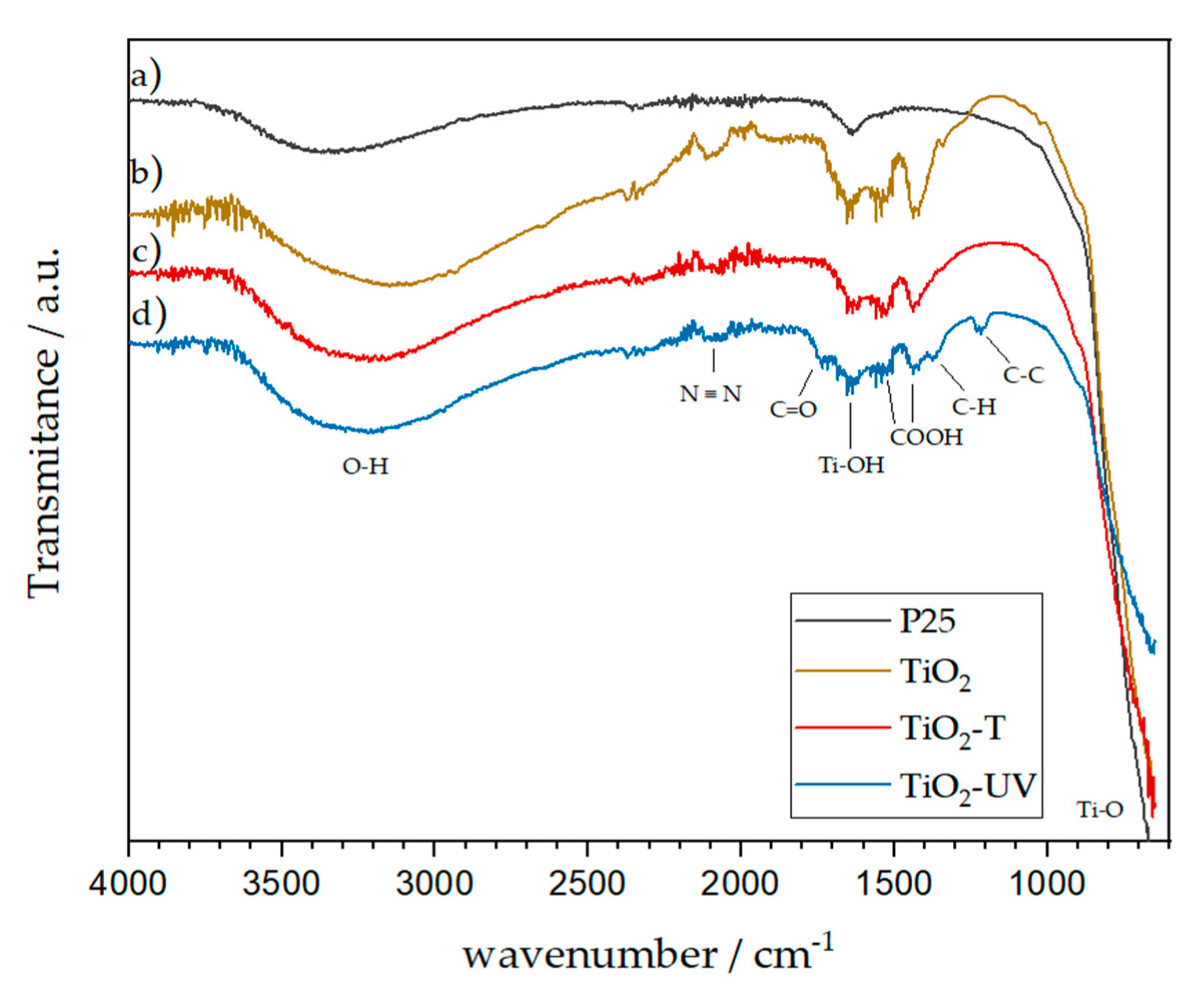
7.1. FT-IR Powder Measurements
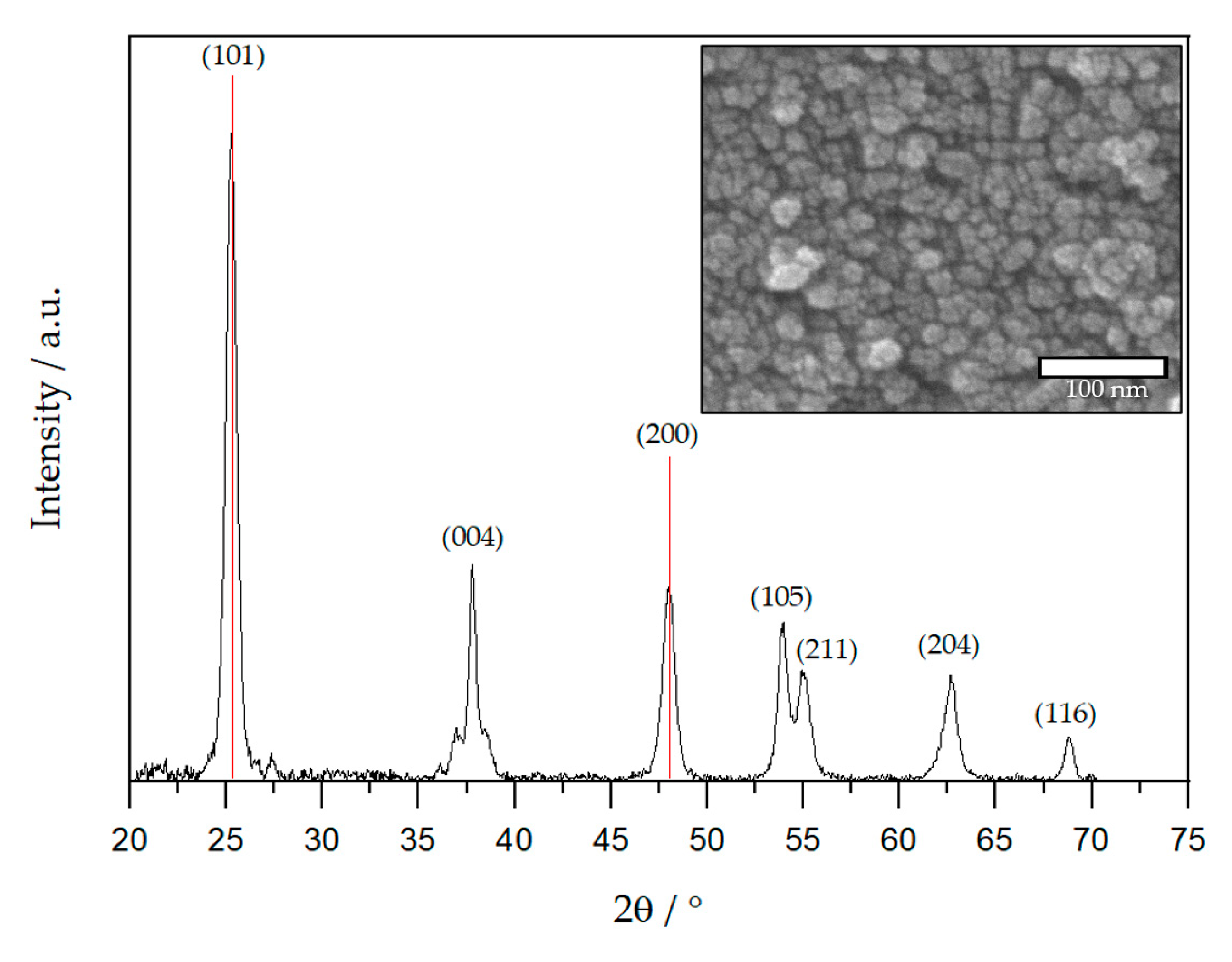
7.2. XRD Characterization TiO2 Nanomaterial
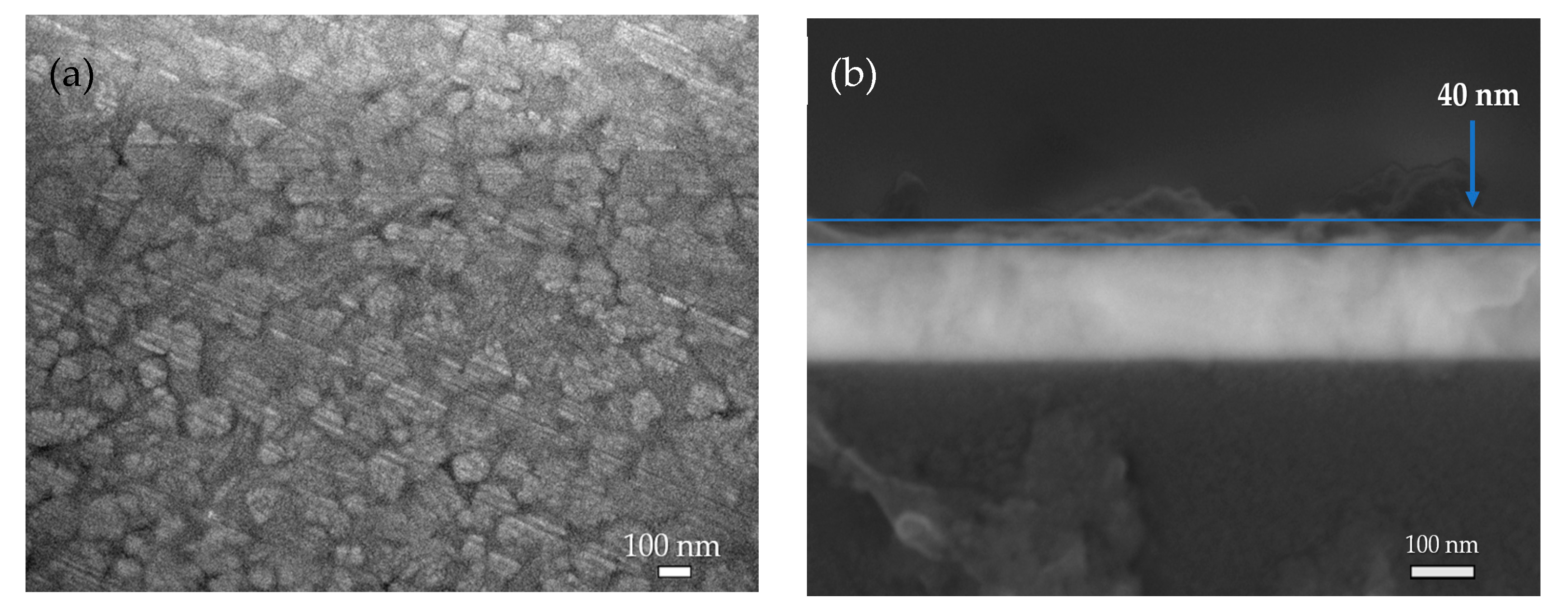
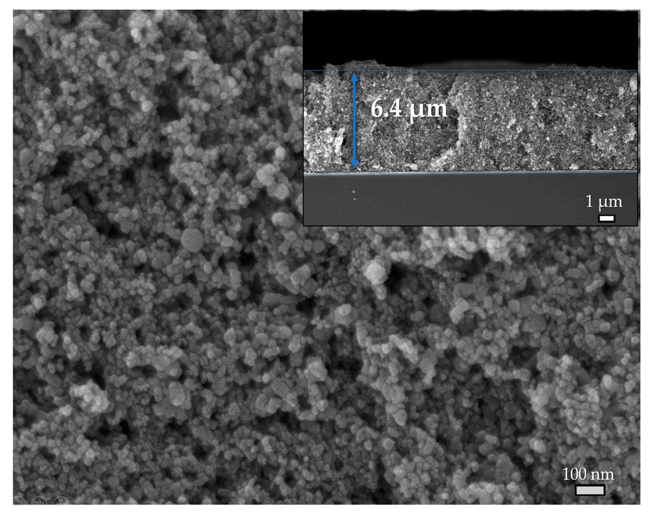
7.3. SEM Images of Deposited Films
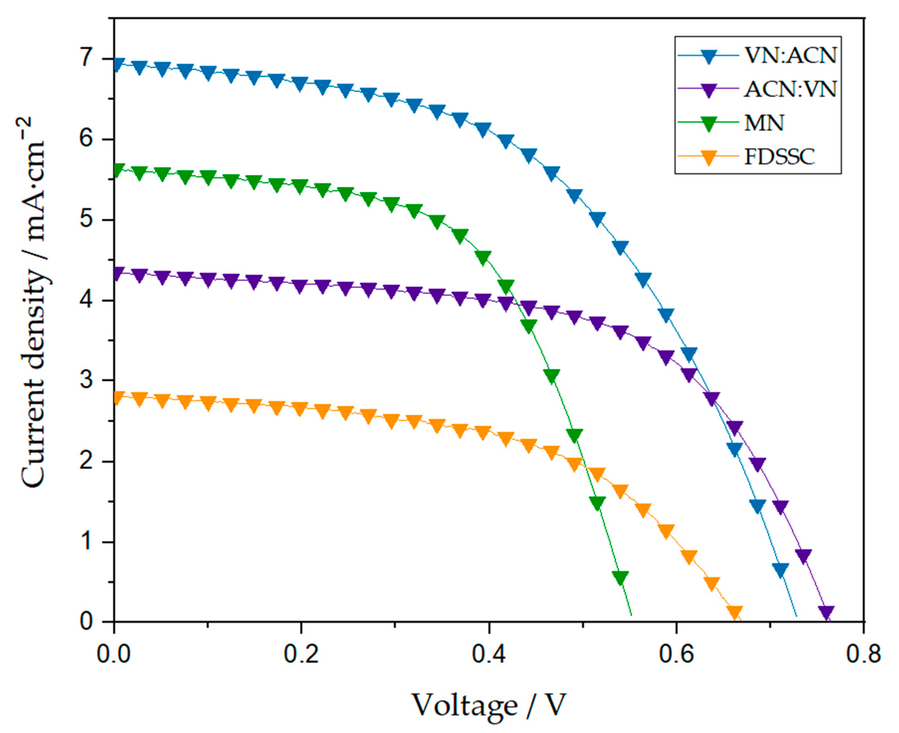
7.4. PV Characterization and J–V Curves of Rigid and F-DSSC
8. Discussion
9. Conclusions
Author Contributions
Funding
Data Availability Statement
Acknowledgments
Conflicts of Interest
References
- Kim, M.B.; Han, H.G.; Roh, D.H.; Park, J.; Kim, K.M.; Kim, U.Y.; Kwon, T.H. Flexible Dye-Sensitized Solar Cells. In Flexible Energy Conversion and Storge Devices, 1st ed.; Zhi, C., Dai, L., Eds.; Wiley-VCH Verlag GmbH & Co.: Weinheim, Germany, 2018; pp. 239–281. [Google Scholar]
- Mozaffari, S.; Nateghi, M.R.; Zarandi, M.B. An overview of the Challenges in the commercialization of dye sensitized solar 1362 cells. Renew. Sustain. Energy Rev. 2017, 71, 675–686. [Google Scholar] [CrossRef]
- Baby, R.; Nixon, P.D.; Kumar, N.M.; Subathra, M.S.P.; Ananthi, N. A comprehensive review of dye-sensitized solar cell 1368 optimal fabrication conditions, natural dye selection, and application-based future perspectives. Environ. Sci. Pollut. Res. 2022, 29, 371–404. [Google Scholar] [CrossRef]
- Gong, J.; Sumathy, K.; Qiao, Q.; Zhou, Z. Review on dye-sensitized solar cells (DSSCs): Advanced techniques and research 1371 trends. Renew. Sustain. Energy Rev. 2017, 68, 234–246. [Google Scholar] [CrossRef]
- Li, G.; Sheng, L.; Li, T.; Hu, J.; Li, P.; Wang, K. Engineering flexible dye-sensitized solar cells for portable electronics. Solar Energy 2018, 177, 80–98. [Google Scholar] [CrossRef]
- Hashmi, G.; Miettunen, K.; Peltola, T.; Halme, J.; Asghar, I.; Aitola, K.; Toivola, M.; Lund, P. Review of materials and manufacturing options for large area flexible dye solar cells. Renew. Sustain. Energy Rev. 2011, 15, 3717–3732. [Google Scholar] [CrossRef] [Green Version]
- Li, B.; Huang, F.; Zhong, J.; Xie, J.; Wen, M.; Pen, Y. Fabrication of Flexible Dye-Sensitized Solar Cell Modules using Commercially Available Materials. Energy Technol. 2016, 4, 536–542. [Google Scholar] [CrossRef]
- Freitag, M.; Teuscher, J.; Saygili, Y.; Zhang, X.; Giordano, F.; Liska, P.; Hua, J.; Zakeeruddin, M.; Moser, J.E.; Grätzel, M.; et al. Dye-sensitized solar cells for efficient power generation under ambient lighting. Nat. Photon. 2017, 11, 372–378. [Google Scholar] [CrossRef] [Green Version]
- Karthick, S.N.; Hemalatha, K.V.; Balasingam, S.K.; Clinton, F.M.; Akshaya, S.; Kim, H. Dye-Sensitized Solar Cells: History, Components, Configuration, and Working Principle. In Interfacial Engineering in Functional Materials for Dye-Sensitized Solar, 1st ed.; Pandikumar, A., Jothivenkatachalam, K., Bhojonaa, K.B., Eds.; Jhon Wiley & Sons: New York, NY, USA, 2020; pp. 1–16. [Google Scholar] [CrossRef]
- Conibeer, G. Third-generation photovoltaics. Mater. Today 2007, 10, 11. [Google Scholar] [CrossRef]
- Yan, J.; Saunders, B.R. Third-generation solar cells: A review and comparison of polymer:fullerene, hybrid polymer and perovskite solar cells. RSC Adv. 2014, 4, 43286. [Google Scholar] [CrossRef] [Green Version]
- Mingsukang, M.A.; Buraidah, M.H.; Arof, A.K. Third-Generation-Sensitized Solar Cells. In Nanostructured Solar Cells, 1st ed.; Das, N., Ed.; InTechOpen: London, UK, 2017; pp. 7–31. [Google Scholar] [CrossRef] [Green Version]
- Mahalingam, S.; Abdullah, H. Electron transport study of indium oxide as photoanode in DSSCs: A review. Renew. Sustain. Energy Rev. 2016, 63, 245–255. [Google Scholar] [CrossRef]
- Buitrago, E.; Novello, A.M.; Meyer, T. Third-Generation Solar Cells: Toxicity and Risk of Exposure. Helv. Chim. Acta 2020, 103, 9. [Google Scholar] [CrossRef]
- George, J.; Joseph, A.P.; Balachandran, M. Perovskites: Emergence of highly efficient third-generation solar cells. Int. J. Energy Res. 2022, 46, 21856–21883. [Google Scholar] [CrossRef]
- Wu, J.; Lan, Z.; Lian, J.; Huang, M.; Huang, Y.; Fan, L.; Luo, G. Electrolytes in dye-sensitized solar cells. Chem. Rev. 2015, 115, 2136–2173. [Google Scholar] [CrossRef]
- National Renewable Energy Laboratory. Available online: https://www.nrel.gov/pv/cell-efficiency.html (accessed on 26 June 2023).
- Toivola, M.; Halme, J.; Miettunen, K.; Aitola, K.; Lund, P.D. Nanostructured dye solar cells on flexible substrates-Review. Int. J. Energy Res. 2009, 33, 1145–1160. [Google Scholar] [CrossRef]
- Yugis, A.R.; Mansa, R.F.; Sipaut, C.S. Review on metallic and plastic flexible dye sensitized solar cell. IOP Conf. Ser. Mater. Sci. Eng. 2015, 78, 012003. [Google Scholar] [CrossRef]
- Nogueira, A.F.; Longo, C.; De Paoli, M.A. Polymers in dye sensitized solar cells: Overview and perspectives. Coord. Chem. Rev. 2004, 248, 1455–1468. [Google Scholar] [CrossRef]
- Miettunen, K.; Halme, J.; Lund, P. Metallic and plastic dye solar cells. WIREs Energy Environ. 2013, 2, 104–120. [Google Scholar] [CrossRef] [Green Version]
- Miettunen, K.; Vapaavuori, J.; Poskela, A.; Tiihonen, A.; Lund, P.D. Recent progress in flexible dye solar cells. WIREs Energy Environ. 2018, 7, e302. [Google Scholar] [CrossRef]
- Mariotti, N.; Bonomo, M.; Fagiolari, L.; Barbero, N.; Gerbaldi, C.; Bella, F.; Barolo, C. Recent advances in eco-friendly and cost-effective materials towards sustainable dye-sensitized solar cells. Green Chem. 2020, 22, 7168–7218. [Google Scholar] [CrossRef]
- James, S.; Contractor, R. Study on Nature-inspired Fractal Design-based Flexible Counter Electrodes for Dye-Sensitized Solar Cells Fabricated using Additive Manufacturing. Sci. Rep. 2018, 8, 17032. [Google Scholar] [CrossRef] [Green Version]
- Lin, L.Y.; Ho, K.C. Dye-sensitized solar cells. In Encyclopedia of Modern Optics, 2nd ed.; Guenther, B.D., Steel, D.G., Eds.; Elsevier Inc.: Amsterdam, The Netherlands, 2018; Volume 5, pp. 270–281. [Google Scholar] [CrossRef]
- Ito, S. Investigation of Dyes for Dye-Sensitized: Ruthenium-Complex Dyes, Metal-Free Dyes, Metal-Complex Porphyrin Dyes. In Solar Cells—Dye-Sensitized Devices, 1st ed.; Kosyachenko, L.A., Ed.; InTechOpen: London, UK, 2011; pp. 19–48. [Google Scholar] [CrossRef] [Green Version]
- Bella, F.; Bongiovanni, R. Photoinduced polymerization: An innovative, powerful and environmentally friendly technique for the preparation of polymer electrolytes for dye-sensitized solar cells. J. Photochem. Photobiol. C. 2013, 16, 1–21. [Google Scholar] [CrossRef]
- Ellis, H.; Vlachopoulos, N.; Häggman, L.; Perruchot, C.; Jouini, M.; Boschloo, G.; Hagfeldt, A. PEDOT counter electrodes for dye-sensitized solar cells prepared by aqueous micellar electrodeposition. Electrochim. Acta 2013, 107, 45–51. [Google Scholar] [CrossRef]
- Hagfeldt, A.; Boschloo, G.; Lindström, H.; Figgemeier, E.; Holmberg, A.; Aranyos, V.; Magnusson, E.; Malmqvist, L. A system approach to molecular solar cells. Coord. Chem. Rev. 2004, 248, 1501–1509. [Google Scholar] [CrossRef]
- Park, N.G.; Kim, K.M.; Kang, M.G.; Ryu, K.S.; Chang, S.H.; Shin, Y.J. Chemical Sintering of Nanoparticles: A Methodology for Low-Temperature Fabrication of Dye-Sensitized TiO2 Films. Adv. Mater. 2005, 17, 2349–2353. [Google Scholar] [CrossRef]
- Lindström, H.; Holmberg, A.; Magnusson, E.; Lindquist, S.E.; Malmqvist, L.; Hagfeldt, A. A New Method for Manufacturing Nanostructured Electrodes on Plastic Substrates. Nano Lett. 2001, 1, 97–100. [Google Scholar] [CrossRef]
- Michaels, H.; Rinderle, M.; Freitag, R.; Benesperi, I.; Edvinsson, T.; Socher, R.; Gagliardi, A.; Freitag, M. Dye-sensitized solar cells under ambient light powering machine learning: Towards autonomous smart sensors for the internet of things. Chem. Sci. 2020, 11, 2895–2906. [Google Scholar] [CrossRef] [Green Version]
- Li, M.; Igbari, F.; Wang, Z.K.; Liao, L.S. Indoor Thin-Film Photovoltaics: Progress and Challenges. Adv. Energy Mater. 2020, 10, 2000641. [Google Scholar] [CrossRef]
- Kim, S.; Jahandar, M.; Jeong, J.H.; Lim, D.C. Recent Progress in Solar Cell Technology for Low-Light Indoor Applications. Curr. Altern. Energy 2019, 3, 3–17. [Google Scholar] [CrossRef]
- Zhang, D.; Stojanovic, M.; Ren, Y.; Cao, Y.; Eickemeyer, F.T.; Socie, E.; Vlachopoulos, N.; Moser, J.-E.; Zakeeruddin, S.M.; Hagfeldt, A.; et al. A molecular photosensitizer achieves a VOC of 1.24 V enabling highly efficient and stable dye-sensitized solar cells with copper(II/I)-based electrolyte. Nat. Commun. 2021, 12, 1777. [Google Scholar] [CrossRef]
- Cao, Y.; Liu, Y.; Zakeeruddin, S.M.; Hagfeldt, A.; Grätzel, M. Direct Contact of Selective Charge Extraction Layers Enables High-Efficiency Molecular Photovoltaics. Joule 2018, 2, 1108–1117. [Google Scholar] [CrossRef] [Green Version]
- Miettunen, K.; Halme, J.; Lund, P. Segmented cell design for improved factoring of aging effects in dye solar cells. J. Phys. Chem. C 2009, 113, 10297–10302. [Google Scholar] [CrossRef] [Green Version]
- Ma, T.; Fang, X.; Akiyama, M.; Inoue, K.; Noma, H.; Abe, E. Properties of several types of novel counter electrodes for dye-sensitized solar cells. J. Electroanal. Chem. 2004, 574, 77–83. [Google Scholar] [CrossRef]
- Karim, N.A.; Mehmood, U.; Zahid, H.F.; Asif, T. Nanostructured photoanode and counter electrode materials for efficient Dye-Sensitized Solar Cells (DSSCs). Sol. Energy 2019, 185, 165–188. [Google Scholar] [CrossRef]
- Sen, A.; Putra, M.H.; Biswas, A.K.; Behera, A.K.; Groß, A. Insight on the choice of sensitizers/dyes for dye sensitized solar cells: A review. Dyes Pigm. 2023, 213, 111087. [Google Scholar] [CrossRef]
- Wu, T.-C.; Huang, W.-M.; Meen, T.-H.; Tsai, J.-K. Performance Improvement of Dye-Sensitized Solar Cells with Pressed TiO2 Nanoparticles Layer. Coatings 2023, 13, 907. [Google Scholar] [CrossRef]
- Senthilarasu, S.; Peiris, T.A.N.; García-Cañadas, J.; Wijayantha, K.G.U. Preparation of nanocrystalline TiO2 electrodes for flexible dye-sensitized solar cells: Influence of mechanical compression. J. Phys. Chem. C 2012, 116, 19053–19061. [Google Scholar] [CrossRef]
- Upadhyaya, H.M.; Senthilarasu, S.; Hsu, M.H.; Kumar, D.K. Recent progress and the status of dye-sensitised solar cell (DSSC) technology with state-of-the-art conversion efficiencies. Sol. Energy Mater. Sol. Cells 2013, 119, 291–295. [Google Scholar] [CrossRef]
- Wante, H.P.; Bala, S.; Romanus, I.O. Review: Low Temperature Sintering of TiO2 for Dye Sensitized Solar Cells (DSSCs) Fabrication on Flexible Substrates. Eur. J. Mater. Sci. 2022, 9, 18–24. [Google Scholar] [CrossRef]
- Inukai, K.; Takahashi, Y.; Ri, K.; Shin, W. Rheological analysis of ceramic pastes with ethyl cellulose for screen-printing. Ceram Int. 2015, 41, 5959–5966. [Google Scholar] [CrossRef]
- Kunzmann, A.; Valero, S.; Sepúlveda, Á.E.; Rico-Santacruz, M.; Lalinde, E.; Berenguer, J.R.; García-Martínez, J.; Guldi, D.M.; Serrano, E.; Costa, R.D. Hybrid Dye-Titania Nanoparticles for Superior Low-Temperature Dye-Sensitized Solar Cells. Adv. Energy Mater. 2018, 8, 1702583. [Google Scholar] [CrossRef] [Green Version]
- Kijitori, Y.; Ikegami, M.; Miyasaka, T. Highly efficient plastic dye-sensitized photoelectrodes prepared by low-temperature binder-free coating of mesoscopic titania pastes. Chem. Lett. 2007, 36, 190–191. [Google Scholar] [CrossRef] [Green Version]
- Weerasinghe, H.C.; Sirimanne, P.M.; Simon, G.P.; Cheng, Y.-B. Cold isostatic pressing technique for producing highly efficient flexible dye-sensitized solar cells on plastic substrates. Prog. Photovolt. 2012, 20, 321–332. [Google Scholar] [CrossRef]
- Morita, S.; Ikegami, M.; Wei, T.C.; Miyasaka, T. Quantum conversion enhancement with TiOx compact layers for ITO-plastic-film-based low-temperature-processed dye-sensitized photoelectrodes. Chem. Phys. Chem. 2014, 15, 1190–1193. [Google Scholar] [CrossRef] [PubMed]
- Zhang, D.; Yoshida, T.; Minoura, H. Low Temperature Synthesis of Porous Nanocrystalline TiO2 Thick Film for Dye-Sensitized Solar Cells by Hydrothermal Crystallization. Chem. Lett. 2002, 31, 874–875. [Google Scholar] [CrossRef]
- Zhang, D.; Yoshida, T.; Furuta, K.; Minoura, H. Hydrothermal preparation of porous nano-crystalline TiO2 electrodes for flexible solar cells. J. Photochem. Photobiol. A Chem. 2004, 164, 159–166. [Google Scholar] [CrossRef]
- Stathatos, E.; Chen, Y.; Dionysiou, D.D. Quasi-solid-state dye-sensitized solar cells employing nanocrystalline TiO2 films made at low temperature. Sol. Energy Mater. Sol. Cells 2008, 92, 1358–1365. [Google Scholar] [CrossRef]
- Weerasinghe, H.C.; Sirimanne, P.M.; Franks, G.V.; Simon, G.P.; Cheng, Y.B. Low temperature chemically sintered nano-crystalline TiO2 electrodes for flexible dye-sensitized solar cells. J. Photochem. Photobiol. A Chem. 2010, 213, 30–36. [Google Scholar] [CrossRef]
- Weerasinghe, H.C.; Franks, G.V.; Plessis, J.D.; Simon, G.P.; Cheng, Y.B. Anomalous rheological behavior in chemically modified TiO2 colloidal pastes prepared for flexible dye-sensitized solar cells. J. Mater. Chem. 2010, 20, 9954–9961. [Google Scholar] [CrossRef]
- Holliman, P.J.; Connell, A.; Davies, M.; Carnie, M.; Bryant, D.; Jones, E.W. Low temperature sintering of aqueous TiO2 colloids for flexible, co-sensitized dye-sensitized solar cells. Mater. Lett. 2019, 236, 289–291. [Google Scholar] [CrossRef]
- Sasi, S.; Chandran, A.; Sugunan, S.K.; Krishna, A.C.; Nair, P.R.; Peter, A.; Shaji, A.N.; Subramanian, K.R.V.; Pai, N.; Mathew, S. Flexible Nano-TiO2 Sheets Exhibiting Excellent Photocatalytic and Photovoltaic Properties by Controlled Silane Functionalization─Exploring the New Prospects of Wastewater Treatment and Flexible DSSCs. ACS Omega 2022, 7, 25094–25109. [Google Scholar] [CrossRef]
- Miyasaka, T.; Ikegami, M.; Kijitori, Y. Photovoltaic Performance of Plastic Dye-Sensitized Electrodes Prepared by Low-Temperature Binder-Free Coating of Mesoscopic Titania. J. Electrochem. Soc. 2007, 154, A455. [Google Scholar] [CrossRef]
- Li, X.; Lin, H.; Li, J.; Wang, N.; Lin, C.; Zhang, L. Chemical sintering of graded TiO2 film at low-temperature for flexible dye-sensitized solar cells. J. Photochem. Photobiol. A Chem. 2008, 195, 247–253. [Google Scholar] [CrossRef]
- Zhang, D.; Downing, J.A.; Knorr, F.J.; McHale, J.L. Room-temperature preparation of nanocrystalline TiO2 films and the influence of surface properties on dye-sensitized solar energy conversion. J. Phys. Chem. B. 2006, 110, 21890–21898. [Google Scholar] [CrossRef] [PubMed]
- Weerasinghe, H.C.; Sirimanne, P.M.; Simon, G.P.; Cheng, Y.B. Fabrication of efficient solar cells on plastic substrates using binder-free ball milled titania slurries. J. Photochem. Photobiol. A Chem. 2009, 206, 64–70. [Google Scholar] [CrossRef]
- Dürr, M.; Schmid, A.; Obermaier, M.; Rosselli, S.; Yasuda, A.; Nelles, G. Low-temperature fabrication of dye-sensitized solar cells by transfer of composite porous layers. Nat. Mater. 2005, 4, 607–611. [Google Scholar] [CrossRef]
- Kim, H.; Piqué, A.; Kushto, G.P.; Auyeung, R.C.Y.; Lee, S.H.; Arnold, C.B.; Kafafi, Z.H. Dye-sensitized solar cells using laser processing techniques. In Photon Processing in Microelectronics and Photonics, 3rd ed.; Dubowski, J.J., Geohegan, D.B., Träger, F., Herman, P.R., Fieret, J., Pique, A., Okada, T., Bachmann, F.G., Hoving, W., Washio, K., et al., Eds.; Proceedings of SPIE; The International Society for Optical Engineering: Bellingham, WA, USA, 2004; Volume 5339, p. 5339A-48. [Google Scholar] [CrossRef]
- Kim, H.; Auyeung, R.C.Y.; Ollinger, M.; Kushto, G.P.; Kafafi, Z.H.; Piqué, A. Laser-sintered mesoporous TiO2 electrodes for dye-sensitized solar cells. Appl. Phys A 2006, 83, 73–76. [Google Scholar] [CrossRef]
- Shen, J.; Cheng, R.; Chen, Y.; Chen, X.; Sun, Z.; Huang, S. A Novel TiO2 Tape for Fabricating Dye-Sensitized Solar Cells on Universal Conductive Substrates. ACS Appl. Mater. Interfaces 2013, 5, 13000–13005. [Google Scholar] [CrossRef]
- Yang, L.; Wu, L.; Wu, M.; Xin, G.; Lin, H.; Ma, T. High-efficiency flexible dye-sensitized solar cells fabricated by a novel friction-transfer technique. Electrochem Commun. 2010, 12, 1000–1003. [Google Scholar] [CrossRef]
- Lindstöm, H.; Södergren, S.; Lindquist, S.; Hagfeldt, A. Method for Manufacturing Nanostructured Thin Film Electrodes. World Intelectual Property. Organization Patent Application No. WO 00/72373 A1, 20 November 2000. [Google Scholar]
- Lindström, H.; Holmberg, A.; Magnusson, E.; Malmqvist, L.; Hagfeldt, A. A new method to make dye-sensitized nano-crystalline solar cells at room temperature. J. Photochem. Photobiol. A Chem. 2001, 145, 107–112. [Google Scholar] [CrossRef]
- Lindström, H.; Magnusson, E.; Holmberg, A.; Södergren, S.-E.; Lindquist, S.-E.; Hagfeldt, A. A new method for manufacturing nanostructured electrodes on glass substrates. Sol. Energy Mater. Sol. Cells 2002, 73, 91–101. [Google Scholar] [CrossRef]
- Lindström, H.; Boschloo, G.; Lindquis, S.-E.; Hagfeldt, A. A New Method for Manufacturing Dye-Sensitized Solar Cells on Plastic Substrates. In Molecules as Components of Electronic Devices—ASC Symposium Series 844; Marya, L., Ed.; American Chemical Society: Washington, DC, USA, 2003; pp. 123–132. [Google Scholar] [CrossRef]
- Boschloo, G.; Lindström, H.; Magnusson, E.; Holmberg, A.; Hagfeldt, A. Optimization of dye-sensitized solar cells prepared by compression method. J. Photochem. Photobiol. A Chem. 2002, 148, 11–15. [Google Scholar] [CrossRef]
- Li, X.; Lin, H.; Li, J.; Li, X.; Cui, B.; Zhang, L. A numerical simulation and impedance study of the electron transport and recombination in binder-free TiO2 film for flexible dye-sensitized solar cells. J. Phys. Chem. C 2008, 112, 13744–13753. [Google Scholar] [CrossRef]
- Zhao, X.; Lin, H.; Li, X.; Li, J. The effect of compression on electron transport and recombination in plastic TiO2 photoanodes. Electrochim. Acta 2011, 56, 6401–6405. [Google Scholar] [CrossRef]
- Yang, H.; Liu, W.; Xu, C.; Fan, D.; Cao, Y.; Xue, W. Laser sintering of TiO2 films for flexible dye-sensitized solar cells. Appl. Sci. 2019, 9., 823. [Google Scholar] [CrossRef] [Green Version]
- Huang, W.M.; Tsai, J.K.; Wu, T.C.; Meen, T.H. Improvement of Dye-sensitized Solar Cells by Using Compact and Pressed Layer of TiO2. In Proceedings of the 2022 5th IEEE International Conference on Knowledge Innovation and Invention, Hualien, Taiwan, 22–24 July 2022; pp. 63–68. [Google Scholar] [CrossRef]
- Yoshida, T.; Oekermann, T.; Okabe, K.; Schlettwein, D.; Funabiki, K.; Minoura, H. Cathodic Electrodeposition of ZnO/EosinY Hybrid Thin Films from Dye Added Zinc Nitrate Bath and Their Photoelectrochemical Characterizations. Electrochemistry 2002, 70, 470–487. [Google Scholar] [CrossRef] [Green Version]
- Tan, W.; Chen, J.; Zhou, X.; Zhang, J.; Lin, Y.; Li, X.; Xiao, X. Preparation of nanocrystalline TiO2 thin film at low temperature and its application in dye-sensitized solar cell. J. Solid State Electrochem. 2009, 13, 651–656. [Google Scholar] [CrossRef]
- Miyasaka, T.; Kijitori, Y. Low-Temperature Fabrication of Dye-Sensitized Plastic Electrodes by Electrophoretic Preparation of Mesoporous TiO2 Layers. J. Electrochem. Soc. 2004, 151, A1767. [Google Scholar] [CrossRef]
- Ferrere, S.; Gregg, B.A. Large increases in photocurrents and solar conversion efficiencies by UV illumination of dye sensitized solar cells. J. Phys. Chem. B. 2001, 105, 7602–7605. [Google Scholar] [CrossRef]
- Rawolle, M.; Niedermeier, M.A.; Kaune, G.; Perlich, J.; Lellig, P.; Memesa, M.; Cheng, Y.-J.; Gutmann, J.S.; Müller-Buschbaum, P. Fabrication and characterization of nanostructured titania films with integrated function from inorganic–organic hybrid materials. Chem. Soc. Rev. 2012, 41, 5131–5142. [Google Scholar] [CrossRef]
- Orilall, M.C.; Wiesner, U. Block copolymer based composition and morphology control in nanostructured hybrid materials for energy conversion and storage: Solar cells, batteries, and fuel cells. Chem. Soc. Rev. 2011, 40, 520–535. [Google Scholar] [CrossRef]
- Nilsson, E.; Sakamoto, Y.; Palmqvist, A.E.C. Low-temperature synthesis and HRTEM analysis of ordered mesoporous anatase with tunable crystallite size and pore shape. Chem. Mater. 2011, 23, 2781–2785. [Google Scholar] [CrossRef]
- Shibata, H.; Ogura, T.; Mukai, T.; Ohkubo, T.; Sakai, H. Direct synthesis of mesoporous titania particles having a crystalline wall. J. Am. Chem. Soc. 2005, 127, 16396–16397. [Google Scholar] [CrossRef] [PubMed]
- Longo, C.; Nogueira, A.F.; De Paoli, M.A.; Cachet, H. Solid-state and flexible dye-sensitized TiO2 solar cells: A study by electrochemical impedance spectroscopy. J. Phys. Chem. B 2002, 106, 5925–5930. [Google Scholar] [CrossRef]
- Longo, C.; Freitas, J.; De Paoli, M.A. Performance and stability of TiO2/dye solar cells assembled with flexible electrodes and a polymer electrolyte. J. Photochem. Photobiol. A Chem. 2003, 159, 33–39. [Google Scholar] [CrossRef]
- Haseloh, S.; Choi, S.Y.; Mamak, M.; Coombs, N.; Petrov, S.; Choprab, N.; Ozin, G.A. Towards flexible inorganic ‘mesomaterials’: One-pot low temperature synthesis of mesostructured nanocrystalline titania. Chem. Commun. 2004, 4, 1460–1461. [Google Scholar] [CrossRef] [PubMed]
- Gutiérrez-Tauste, D.; Zumeta, I.; Vigil, E.; Hernández-Fenollosa, M.A.; Domènech, X.; Ayllón, J.A. New low-temperature preparation method of the TiO2 porous photoelectrode for dye-sensitized solar cells using UV irradiation. J. Photochem. Photobiol. A Chem. 2005, 175, 165–171. [Google Scholar] [CrossRef]
- Nemoto, J.; Sakata, M.; Hoshi, T.; Ueno, H.; Kaneko, M. All-plastic dye-sensitized solar cell using a polysaccharide film containing excess redox electrolyte solution. J. Electroanal. Chem. 2007, 599, 23–30. [Google Scholar] [CrossRef]
- Tebby, Z.; Babot, O.; Toupance, T.; Park, D.H.; Campet, G.; Delville, M.H. Low-temperature UV-processing of nano-crystalline nanoporous Thin TiO2 films: An original route toward plastic electrochromic systems. Chem. Mater. 2008, 20, 7260–7267. [Google Scholar] [CrossRef]
- Tebby, Z.; Babot, O.; Michau, D.; Hirsch, L.; Carlos, L.; Toupance, T. A simple route towards low-temperature processing of nanoporous thin films using UV-irradiation: Application for dye solar cells. J. Photochem. Photobiol. A Chem. 2009, 205, 70–76. [Google Scholar] [CrossRef]
- Miyasaka, T.; Kijitori, Y.; Murakami, T.N.; Kimura, M.; Uegusa, S. Efficient Nonsintering Type Dye-sensitized Photocells Based on Electrophoretically Deposited TiO2 Layers. Chem. Lett. 2002, 31, 1250–1251. [Google Scholar] [CrossRef]
- Murakami, T.N.; Kijitori, Y.; Kawashima, N.; Miyasaka, T. UV Light-assisted Chemical Vapor Deposition of TiO2 for Efficiency Development at Dye-sensitized Mesoporous Layers on Plastic Film Electrodes. Chem Lett. 2003, 32, 1076–1077. [Google Scholar] [CrossRef]
- Murakami, T.N.; Kijitori, Y.; Kawashima, N.; Miyasaka, T. Low temperature preparation of mesoporous TiO2 films for efficient dye-sensitized photoelectrode by chemical vapor deposition combined with UV light irradiation. J. Photochem. Photobiol. A Chem. 2004, 164, 187–191. [Google Scholar] [CrossRef]
- Uchida, S.; Tomiha, M.; Takizawa, H.; Kawaraya, M. Flexible dye-sensitized solar cells by 28 GHz microwave irradiation. J. Photochem. Photobiol. A Chem. 2004, 164, 93–96. [Google Scholar] [CrossRef]
- Kado, T.; Yamaguchi, M.; Yamada, Y.; Hayase, S. Low Temperature Preparation of Nano-porous TiO2 Layers for Plastic Dye Sensitized Solar Cells. Chem. Lett. 2003, 32, 1056–1057. [Google Scholar] [CrossRef]
- ISO 15184:2020; Paints and varnishes–Determination of films hardness by pencil test. International Organization for Standarization: Geneva, Switzerland, 2012. Available online: https://www.iso.org/standard/76044.html (accessed on 26 June 2023).
- Yamaguchi, T.; Tobe, N.; Matsumoto, D.; Arakawa, H. Highly efficient plastic substrate dye-sensitized solar cells using a compression method for preparation of TiO2 photoelectrodes. Chem. Commun. 2007, 45, 4767–4769. [Google Scholar] [CrossRef]
- Yamaguchi, T.; Tobe, N.; Matsumoto, D.; Nagai, T.; Arakawa, H. Highly efficient plastic-substrate dye-sensitized solar cells with validated conversion efficiency of 7.6%. Sol. Energy Mater. Sol. Cells 2010, 94, 812–816. [Google Scholar] [CrossRef]
- Grinis, L.; Dor, S.; Ofir, A.; Zaban, A. Electrophoretic deposition and compression of titania nanoparticle films for dye-sensitized solar cells. J. Photochem. Photobiol. A Chem. 2008, 198, 52–59. [Google Scholar] [CrossRef]
- Miyoshi, K.; Numao, M.; Ikegami, M.; Miyasaka, T. Effect of Thin TiO2 Buffer on the Performance of Plastic-based Dye-sensitized Solar Cells Using Indoline Dye. Electrochemistry 2007, 76, 158–160. [Google Scholar] [CrossRef] [Green Version]
- Lee, K.-M.; Wu, S.-J.; Chen, C.-Y.; Wu, C.-G.; Ikegami, M.; Miyoshi, K.; Miyasaka, T.; Ho, K.-C. Efficient and stable plastic dye-sensitized solar cells based on a high light-harvesting ruthenium sensitizer. J. Mater. Chem. 2009, 19, 5009–5015. [Google Scholar] [CrossRef]
- Haque, S.A.; Palomares, E.; Upadhyaya, H.M.; Otley, L.; Potter, R.J.; Holmes, A.B.; Durrant, J.R. Flexible dye sensitized nanocrystalline semiconductor solar cells. Chem. Commun. 2003, 3, 3008–3009. [Google Scholar] [CrossRef]
- Lee, K.-M.; Hsu, Y.-C.; Ikegami, M.; Miyasaka, T.; Thomas, K.R.J.; Lin, J.T.; Ho, K.-C. Co-sensitization promoted light harvesting for plastic dye-sensitized solar cells. J. Power Sources 2011, 196, 2416–2421. [Google Scholar] [CrossRef]
- Kim, J.; Lee, H.; Kim, D.Y.; Seo, Y. Resonant multiple light scattering for enhanced photon harvesting in dye-sensitized solar cells. Adv. Mater. 2014, 26, 5192–5197. [Google Scholar] [CrossRef]
- Kim, J.; Lee, H.; Kim, D.Y.; Kim, S.; Seo, Y. Cobalt-based electrolytes for efficient flexible dye-sensitized solar cells. MRS Adv. 2019, 4, 481–489. [Google Scholar] [CrossRef]
- Pichot, F.; Pitts, J.R.; Gregg, B.A. Low-temperature sintering of TiO2 colloids: Application to flexible dye-sensitized solar cells. Langmuir 2000, 16, 5626–5630. [Google Scholar] [CrossRef]
- Zhang, D.; Yoshida, T.; Minoura, H. Low-temperature fabrication of efficient porous titania photoelectrodes by hydrothermal crystallization at the solid/gas interface. Adv. Mater. 2003, 15, 814–817. [Google Scholar] [CrossRef]
- Senthilkumar, S.; Rajendran, A. Biosynthesis of TiO2 nanoparticles using Justicia gendarussa leaves for photocatalytic and toxicity studies. Res. Chem. Intermed. 2018, 44, 5923–5940. [Google Scholar] [CrossRef]
- Jin Joo, J.; Kwon, S.G.; Yu, T.; Cho, M.; Lee, J.; Yoon, J.; Hyeon, T. Large-scale synthesis of TiO2 nanorods via nonhydrolytic sol-gel ester elimination reaction and their application to photocatalytic inactivation of E. coli. J. Phys. Chem. B 2005, 109, 15297–15302. [Google Scholar] [CrossRef]
- Filippo, E.; Carlucci, C.; Capodilupo, A.L.; Perulli, P.; Conciauro, F.; Corrente, G.A.; Gigli, G.; Ciccarella, G. Enhanced photocatalytic activity of pure anatase TiO2 and Pt-TiO2 nanoparticles synthesized by green microwave-assisted route. Mater. Res. 2015, 18, 473–481. [Google Scholar] [CrossRef] [Green Version]
- Tao, P.; Li, Y.; Rungta, A.; Viswanath, A.; Gao, J.; Benicewicz, B.C.; Siegel, R.W.; Schadler, L.S. TiO2 nanocomposites with high refractive index and transparency. J. Mater. Chem. 2011, 21, 18623–18629. [Google Scholar] [CrossRef]
- Saleh, T.A. Structural characterization of hybrid materials. In Polymer Hybrid Materials and Nanocomposites, 1st ed.; Payne, E., Mearns, J., Eds.; Elsevier: Amsterdam, The Netherlands, 2021; pp. 213–240. [Google Scholar] [CrossRef]
- Wante, H.P.; Aidan, J.; Ezike, S.C. Efficient dye-sensitized solar cells (DSSCs) through atmospheric pressure plasma treatment of photoanode surface. Curr. Res. Green Sustain. Chem. 2021, 4, 100218. [Google Scholar] [CrossRef]
- Feldt, S.M.; Lohse, P.W.; Kessler, F.; Nazeeruddin, M.K.; Grâtzel, M.; Boschloo, G.; Hagfeldt, A. Regeneration and recombination kinetics in cobalt polypyridine based dye-sensitized solar cells, explained using Marcus theory. Phys. Chem. Chem. Phys. 2013, 15, 7087–7097. [Google Scholar] [CrossRef] [PubMed]
- Masud, N.; Kim, H.K. Redox Shuttle-Based Electrolytes for Dye-Sensitized Solar Cells: Comprehensive Guidance, Recent Progress, and Future Perspective. ACS Omega 2023, 8, 6139–6163. [Google Scholar] [CrossRef] [PubMed]
- Fabregat-Santiago, F.; Bisquert, J.; Palomares, E.; Otero, L.; Kuang, D.; Zakeeruddin, S.M.; Gra1tzel, M. Correlation between Photovoltaic Performance and Impedance Spectroscopy of Dye-Sensitized Solar Cells Based on Ionic Liquids. J. Phys. Chem. C 2007, 111, 6550–6560. [Google Scholar] [CrossRef]
- Guillén, E.; Fernández-Lorenzo, C.; Alcántara, R.; Martín-Calleja, J.; Anta, J.A. Solvent-free ZnO dye-sensitized solar cells. Sol. Energy Mater. Sol. Cells 2009, 93, 1846–1852. [Google Scholar] [CrossRef]
- Juang, S.S.-Y.; Lin, P.-Y.; Lin, Y.-C.; Chen, Y.-S.; Shen, P.-S.; Guo, Y.-L.; Wu, Y.-C.; Chen, P. Energy harvesting under dim-light condition with dye-sensitized and perovskite solar cells. Front. Chem. 2019, 7, 209. [Google Scholar] [CrossRef] [Green Version]
- Idígoras, J.; Pellejà, L.; Palomares, E.; Anta, J.A. The redox pair chemical environment influence on the recombination loss in dye-sensitized solar cells. J. Phys. Chem. C 2014, 118, 3878–3889. [Google Scholar] [CrossRef]
- Holliman, P.J.; Mohsen, M.; Connell, A.; Kershaw, C.P.; Meza-Rojas, D.; Jones, E.W.; Geatches, D.; Sen, K.; Hsiao, Y.-W. Double linker triphenylamine dyes for dye-sensitized solar cells. Energies 2020, 13, 4637. [Google Scholar] [CrossRef]
- Sharma, K.; Sharma, V.; Sharma, S.S. Dye-Sensitized Solar Cells: Fundamentals and Current Status. Nanoscale Res. Lett. 2018, 13, 381. [Google Scholar] [CrossRef]
- Boschloo, G.; Hagfeldt, A. Characteristics of the iodide/triiodide redox mediator in dye-sensitized solar cells. Acc. Chem. Res. 2009, 42, 1819–1826. [Google Scholar] [CrossRef]
- Kalaignan, G.P.; Kang, Y.S. A review on mass transport in dye-sensitized nanocrystalline solar cells. J. Photochem. Photobiol. C 2006, 7, 17–22. [Google Scholar] [CrossRef]
- Biswas, S.; Kim, H. Solar cells for indoor applications: Progress and development. Polymers 2020, 12, 1338. [Google Scholar] [CrossRef] [PubMed]
- De Rossi, F.; Pontecorvo, T.; Brown, T.M. Characterization of photovoltaic devices for indoor light harvesting and customization of flexible dye solar cells to deliver superior efficiency under artificial lighting. Appl. Energy 2015, 156, 413–422. [Google Scholar] [CrossRef]


| Substrate Type | Applied T (°C)/Time (h) | Strategy Applied to the Low-T Films | Deposition Method | Active Layer Compositions | Thickness (μm) | Dye | Electrolyte | Counter Electrode | PCE (%) at 1 Sun | Ref. |
|---|---|---|---|---|---|---|---|---|---|---|
| ITO-PET | 100/12 | Laser direct-write technique | - | Colloidal TiO2 paste of P25, Degussa), water, acetylacetone, Triton X-100, PEG | 12 | N3 | I−/I3−-based | E-beam-evaporated-pt | 0.71 | [62,63] |
| FTO glass | 100/24 | - | Spin coating | Synthesized colloidal TiO2 solution | 1 | N3 | I−/I3−-based | Pt-coated FTO glass | 1.22 | [105] |
| ITO-PET | Room T | Compression by rollers | Doctor blade | P25, ethanol | 8 | N719 | I−/I3−-based | Porous carbon and porous platinized | 2.3 | [66,67,68,69] |
| ITO-PET | Room T | Compression | Doctor blade | P25, ethanol | 12 | Black and red dye | I−/I3−-based | Platinized SnO2 powder pressed on ITO-PET | 5.5 | [70] |
| ITO-PET | Room T | Compression (adjusting the pressure and thickness of the deposited layer) | Doctor blade | P25, ethanol or water | - | N719 | I−/I3−-based | Platinized Sb-doped SnO2 | 2–3 (6.1% at 0.1 sun) | [29] |
| PET-ITO | <80 | UV irradiation | Doctor blade | P25, TALH solution, Triton X-100, water | 12 | N3 | I−/I3−-based | Pt-coated FTO glass | 2% | [86] |
| PET-ITO | 130/4 | UV irradiation | Doctor blade | commercial TiO2 suspension (Solaronix) | - | N719 | Polymer electrolyte | Sputtered Pt on PET-ITO | 0.23 | [84] |
| ITO-PET | - | Compression using stainless-steel plates and using Al2O3 electron recombination blocking layer | Doctor blade | P25, dry ethanol | 8 | Ru-based | Polymer electrolyte | Sputtered Pt on ITO-PET | 2.5 (5.3% at 0.1 sun) | [101] |
| ITO-PET | 50 | Accelerating electron-beam (EB) shower | Doctor blade | TiO2 paste of P25 in ethyl alcohol | 10 | N3 | I−/I3−-based | Pt-coated FTO glass | 2.1 | [94] |
| ITO-PET | 80/20 | Chemical vapor deposition + UV irradiation + microwave irradiation | Electrophoretic deposition | Commercial TiO2 (F-5), tert-butyl alcohol, acetonitrile | 10 | Ru-based | I−/I3−-based | Pt-coated FTO glass | 3.8 | [91,92] |
| FTO glass | 100/12 | Hydrothermal crystallization of TiCl4 as a chemical glue | Doctor blading | Commercial P25, TiCl4 | 10 | Ru-based | I−/I3−-based | Pt-coated FTO glass | 6.23 | [50] |
| ITO-PET | - | Multi-mode microwave heating | Spray coating | Slurry of synthesized TiO2 nanoparticles | 60 | Ru-based | I−/I3−-based | Pt-coated FTO glass | 2.16 | [93] |
| ITO-PET | Room T | Laser-assisted lift-off combined with a roll-pressing process | Mechanical pressing and transferring | Sintered TiO2 tape | 14 | N719 | - | Hydrolysis Pt counter electrode | 4.2 | [64] |
| ITO-PET | Room T | In situ hydrolysis using TTIP, UV ozone treatment | Doctor blade | P25, TTIP, ethanol | 8 | N3 | I−/I3−-based | Platinized ITO-PET | 3.27 | [106] |
| FTO | 150/0.25 | Acid–base chemistry | Doctor blade | Synthesized TiO2 particles, ammonia solution | 4.3 | N719 | I−/I3−-based | Pt-coated FTO | 2.55 | [30] |
| ITO-PEN | <150 | Using binding agent (HCl) | Doctor blade or screen printing | Colloidal solution of TiO2 with different particle sizes | 10 | N719 | I−/I3−-based with different solvents | Pt-coated FTO glass | 5.8 (6.4% at 0.23 sun) | [47] |
| ITO-PEN | 130 | Surface treatment of ITO using sputtered TiOx layer as a buffer layer followed by anodization | Doctor blade | Commercial binder-free paste (Peccell) | 12 | D149 | I−/I3−-based | Pt-coated FTO glass | 3.7 | [99] |
| ITO-PEN | <150 | Sputtered TiOx layer as a buffer layer followed by anodization, and using co-adsorbent | Doctor blade | Synthesized TiO2 nanoparticles with different sizes, tert-butanol, water | 10 | N719, SJW-E1 | I−/I3−-based with different solvents | Pt-sputtered FTO glass | 6.31 | [100] |
| ITO-PEN | 150 | TiOx compact blocking layer | Doctor blade | Binder-free TiO2 paste | 3.5 | D205 | I−/I3−-based | Pt-sputtered FTO glass | 5.2 | [49] |
| ITO-PET | Air drying | Surface-modified TiO2 nanoparticles | Doctor blade | Synthesized TiO2 nanoparticles, methyl glycine, trimethoxy silane, toluene | 33 | N749 and N719 | I−/I3−-based and Co-based | Platinum coated | 4.1 | [56] |
| ITO-PET | 120 | Condensation protonation–dehydration reaction using H2TiF6 as a binding agent to chemically sinter the TiO2 particles | Doctor blade | P25, H2TiF6, water | - | N719 and SQ1 | I−/I3−-based | Pt-coated | 4.2 | [55] |
| ITO-PEN | 120/0.25 | Cold isostatic pressing (CIP)+ laser sintering | Doctor blade | P25, ethanol followed by ball-milling | 13 | N719 | I−/I3−-based | Pt-coated ITO-PEN | 5.7 | [73] |
| ITO-PEN | 150 | Combination of compression method and light confining effect of TiO2–water paste | Doctor blade | Paste of TiO2 nanoparticles with different sizes and ethanol | 4–8 | N719 | I−/I3−-based | Pt-sputtered ITO-PEN | 7.4 | [48] |
| ITO-PEN | Room T | Compression method | Doctor blade | Paste of TiO2 nanoparticles with two different sizes and ethanol | 6–10 | N719 | I−/I3−-based | Pt-sputtered ITO-PEN or Ti foil | 7.6 | [97] |
| ITO-PET | 200 | Lift-off technique + compression method | Transfer process | TiO2 nanosphere and nanorods | 8–10 | Ru-based | Polymer gel based on I−/I3− | Pt-evaporated ITO-PET | 5.8 | [61] |
| ITO-PET | 150 | Post-treatment with TiO2 sol | Electrophoretic deposition | Commercial TiO2 (F-5 and G-2), t-butyl alcohol, acetonitrile | 5–20 | N719 | I−/I3−-based | FTO glass | 4.1 (4.3% at 0.23 sun) | [77] |
| ITO-PEN | 150/0.5 | Ball milling | Doctor blade or spin coating | P25, ethanol | 1–16 | N719 | I−/I3−-based | Pt-coated ITO-PEN | 4.2 | [60] |
| ITO-PEN | 150/0.5 | Ball milling + chemically modification of slurry with HCl | Doctor blade | P25, ethanol | 8 | N719 | I−/I3−-based | Pt-coated ITO-PEN | 5.0 | [53] |
| ITO-PEN | 150/0.5 | Ball milling + chemically modification of slurry with HCl and ammonia | Doctor blade | P25, ethanol | 10.3 | N719 | I−/I3−-based | Pt-coated ITO-PEN | 4.9 | [54] |
| ITO-PET | Air drying | Cold isostatic pressure (CIP) | Doctor blade | Commercial P25 | 17.5 | N719 | I−/I3−-based | Pt-coated ITO-PEN | 6.3 (7.4% at 0.15 sun) | [48] |
| ITO-PEN | 100/2 | UV irradiation and heat treatment | Spin coating | P25, acetylacetone, water, triton X-100 | 10–15 | N3, N719 | I−/I3−-based liquid electrolyte and solid electrolyte based on polysaccharide | Pt-coated ITO-PEN | 2.63 | [87] |
| ITO-PEN | 150 | Low-temperature chemical sintering of the graded film | doctor blade | P25 and TiO2 (12, 28, and 100 nm) | 3–4 | K-N719 | I−/I3−-based | Pt-coated FTO glass | 3.05 | [58] |
| ITO-PET | 100/30 | Alkoxide hydrolysis of TIIP, resulting in an interconnection between the particles | Dip coating | Nanocrystalline colloid of titanium isopropoxide (TIIP) in an ethanolic dispersion of commercial P25 | 2 | Ru-based | Synthesized gel electrolyte based on I−/I3− | Platinized ITO-PET | 3.2 (3.4% at 0.125 sun) | [52] |
| ITO-PET | - | Direct UV irradiation of the oxide nanoparticles and using light scattering particles | Coating with a glass rod | Synthesized TiO2, pentan-2,4-dione, Triton X-100, water | 1.1 and 2.3 | N3 | I−/I3−-based | Pt-coated FTO glass | 2.5 | [89] |
| ITO-PEN | 125/1 | Friction-transfer technique + compression method | Spray coating | Paste of P25, TBT, ethanol | 28 | N719 | I−/I3−-based | Pt-coated ITO-PEN | 5.7 | [65] |
| ITO-PEN | 150 | Using smaller particles for interconnection between bigger particles | Doctor blade | Paste of TiO2 nanoparticles (9, 23, and 60 nm) | 5–6 | KN-719 | I−/I3−-based | Platinized ITO glass | 3.93 | [71] |
| ITO-PEN | Air drying | Compression method | Doctor blade | Paste TiO2 nanoparticles with different sizes | 6–12 | N719 | I−/I3−-based | Pt-coated ITO-PEN | 4.21 | [72] |
| ITO-PEN | 150/0.16 | - | Doctor blade | commercial binder-free TiO2 paste (Peccell) | 10 | co-sensitization FL and N719, FL and black dye | I−/I3−-based | Pt-sputtered FTO glass | 5.10 | [102] |
| ITO-PEN | 140/0.5 | Compression | Doctor blade | binder-free colloidal suspension of commercial P25 | - | N719 | I−/I3−-based | Pt-coated ITO-PEN | 4.39 | [42] |
| ITO-PEN | Room T | Resonant multiple light scattering effect | Electrospray coating | Hierarchically structured TiO2 and P25 | 3–12 | JH-1 | Co-based | Pt-Ti-sputtered ITO-PEN | 6.12 | [104] |
| ITO-PEN | 120 | Using binding agent H2TiF6 to interconnect the particles | Doctor blade | Homemade TiO2 nanoparticles, H2TiF6, water | 6.4 | N719 | I−/I3— based with different solvents | PEDOT-coated ITO-PEN | 1.0 | This work |
| ACN:VN Device | VOC/V | JSC/mA cm−2 | FF | η/% |
|---|---|---|---|---|
| 1 | 0.76 | 4.30 | 0.59 | 1.94 |
| 2 | 0.76 | 4.36 | 0.59 | 1.97 |
| 3 | 0.69 | 2.92 | 0.54 | 1.10 |
| 4 | 0.76 | 4.23 | 0.59 | 1.92 |
| 5 | 0.70 | 3.45 | 0.58 | 1.71 |
| Average ± SD | 0.73 ± 0.02 | 3.85 ± 0.28 | 0.58 ± 0.02 | 1.73 ± 0.16 |
| VN:ACN Device | VOC/V | JSC/mA cm−2 | FF | η/% |
|---|---|---|---|---|
| 1 | 0.69 | 6.82 | 0.54 | 2.05 |
| 2 | 0.73 | 6.89 | 0.51 | 2.59 |
| 3 | 0.71 | 6.94 | 0.51 | 2.62 |
| 4 | 0.73 | 6.82 | 0.51 | 2.58 |
| 5 | 0.72 | 6.92 | 0.51 | 2.61 |
| Average ± SD | 0.72 ± 0.01 | 6.60 ± 0.29 | 0.52 ± 0.01 | 2.49 ± 0.11 |
| MN Devices | VOC/V | JSC/mA cm−2 | FF | η/% |
|---|---|---|---|---|
| 1 | 0.55 | 5.56 | 0.58 | 1.78 |
| 2 | 0.55 | 5.60 | 0.57 | 1.78 |
| 3 | 0.55 | 5.64 | 0.57 | 1.79 |
| 4 | 0.56 | 3.02 | 0.60 | 1.03 |
| 5 | 0.55 | 5.57 | 0.58 | 1.78 |
| Average ± SD | 0.55 ± 0.01 | 5.08 ± 0.51 | 0.58 ± 0.01 | 1.63 ± 0.15 |
| F-DSSC | VOC/V | JSC/mA cm−2 | FF | η/% |
|---|---|---|---|---|
| 1 | 0.65 | 3.13 | 0.37 | 0.77 |
| 2 | 0.66 | 2.81 | 0.52 | 1.00 |
| 3 | 0.67 | 2.45 | 0.59 | 0.98 |
| 4 | 0.66 | 2.42 | 0.60 | 0.97 |
| 5 | 0.67 | 2.47 | 0.59 | 0.99 |
| Average ± SD | 0.67 ± 0.01 | 2.73 ± 0.11 | 0.54 ± 0.43 | 0.97 ± 0.05 |
| Device | VOC/V | JSC/mA cm−2 | FF | η/% |
|---|---|---|---|---|
| ACN:VN a | 0.73 ± 0.02 | 3.85 ± 0.28 | 0.58 ± 0.02 | 1.73 ± 0.16 |
| VN:ACN a | 0.72 ± 0.01 | 6.60 ± 0.29 | 0.52 ± 0.01 | 2.49 ± 0.11 |
| MN a | 0.55 ± 0.01 | 5.08 ± 0.51 | 0.58 ± 0.01 | 1.63 ± 0.15 |
| F-DSSC b | 0.67 ± 0.01 | 2.73 ± 0.11 | 0.54 ± 0.43 | 0.97 ± 0.05 |
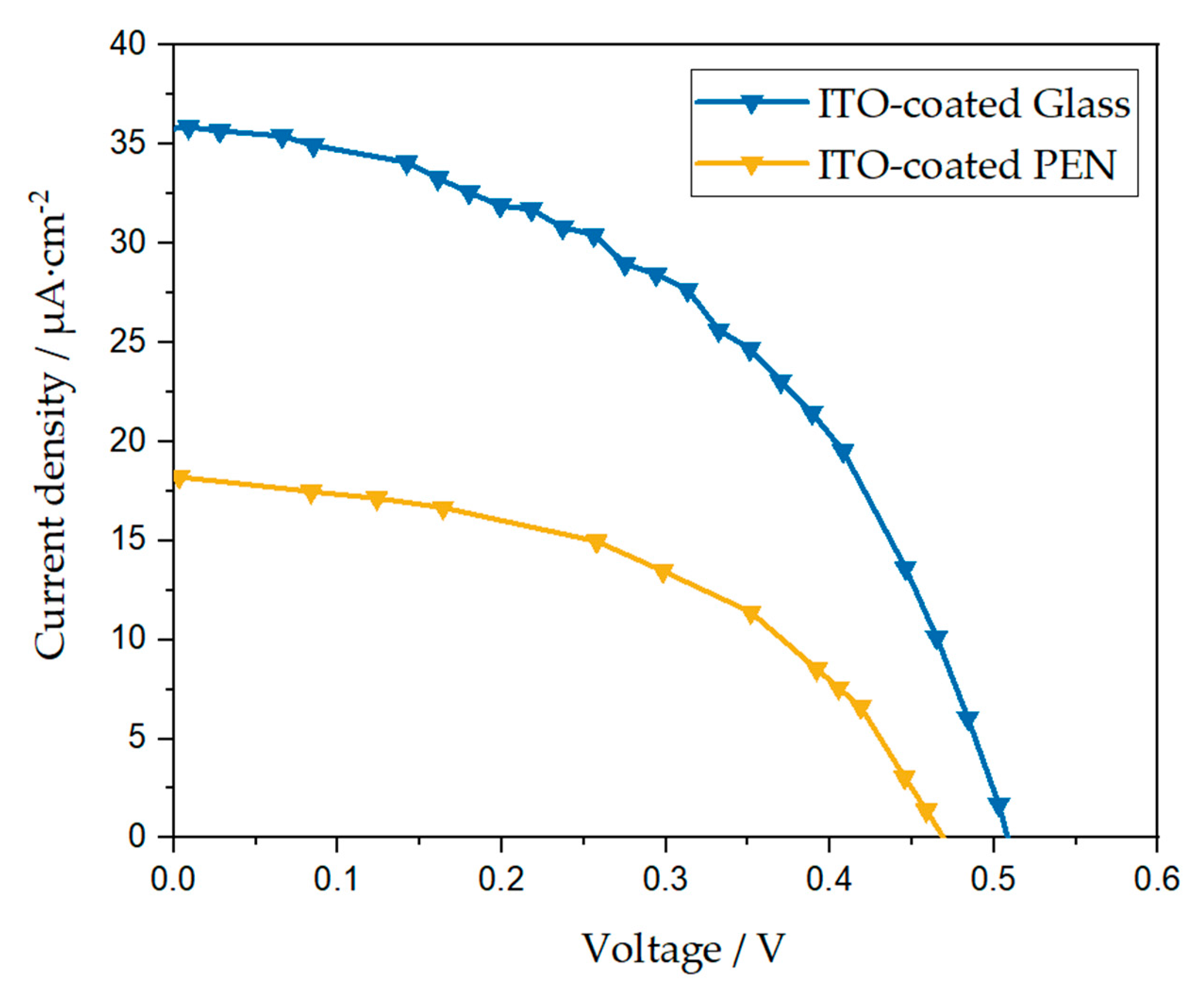
| DSSC | VOC/V | JSC/μA cm−2 | FF | MPO/μW cm−2 |
|---|---|---|---|---|
| 1 | 0.52 | 35.60 | 0.46 | 8.66 |
| 2 | 0.52 | 34.42 | 0.47 | 8.51 |
| 3 | 0.52 | 35.69 | 0.46 | 8.66 |
| 4 | 0.54 | 32.42 | 0.45 | 8.02 |
| 5 | 0.55 | 35.40 | 0.44 | 8.76 |
| Average ± SD | 0.53 ± 0.01 | 34.70 ± 0.61 | 0.45 ± 0.01 | 8.52 ± 0.13 |
| F-DSSC | VOC/V | JSC/μA cm−2 | FF | MPO/μW cm−2 |
|---|---|---|---|---|
| 1 | 0.47 | 18.27 | 0.46 | 4.02 |
| 2 | 0.47 | 17.11 | 0.47 | 4.26 |
| 3 | 0.44 | 17.59 | 0.47 | 3.76 |
| 4 | 0.46 | 15.17 | 0.52 | 3.71 |
| 5 | 0.46 | 15.24 | 0.45 | 3.21 |
| Average ± SD | 0.46 ± 0.01 | 16.67 ± 0.63 | 0.47 ± 0.01 | 3.80 ± 0.17 |
| Device | VOC/V | JSC/μA cm−2 | FF | MPO/μW cm−2 |
|---|---|---|---|---|
| ITO-coated Glass | 0.53 ± 0.01 | 34.70 ± 0.61 | 0.45 ± 0.01 | 8.52 ± 0.13 |
| ITO-coated PEN | 0.46 ± 0.01 | 16.67 ± 0.63 | 0.47 ± 0.01 | 3.80 ± 0.17 |
Disclaimer/Publisher’s Note: The statements, opinions and data contained in all publications are solely those of the individual author(s) and contributor(s) and not of MDPI and/or the editor(s). MDPI and/or the editor(s) disclaim responsibility for any injury to people or property resulting from any ideas, methods, instructions or products referred to in the content. |
© 2023 by the authors. Licensee MDPI, Basel, Switzerland. This article is an open access article distributed under the terms and conditions of the Creative Commons Attribution (CC BY) license (https://creativecommons.org/licenses/by/4.0/).
Share and Cite
Avilés-Betanzos, R.; Oskam, G.; Pourjafari, D. Low-Temperature Fabrication of Flexible Dye-Sensitized Solar Cells: Influence of Electrolyte Solution on Performance under Solar and Indoor Illumination. Energies 2023, 16, 5617. https://doi.org/10.3390/en16155617
Avilés-Betanzos R, Oskam G, Pourjafari D. Low-Temperature Fabrication of Flexible Dye-Sensitized Solar Cells: Influence of Electrolyte Solution on Performance under Solar and Indoor Illumination. Energies. 2023; 16(15):5617. https://doi.org/10.3390/en16155617
Chicago/Turabian StyleAvilés-Betanzos, Roberto, Gerko Oskam, and Dena Pourjafari. 2023. "Low-Temperature Fabrication of Flexible Dye-Sensitized Solar Cells: Influence of Electrolyte Solution on Performance under Solar and Indoor Illumination" Energies 16, no. 15: 5617. https://doi.org/10.3390/en16155617