
Fundamental Understanding of Dye Coverage and Performance in Dye-Sensitized Solar Cells Using Copper Electrolyte

Abstract
:1. Introduction
2. Materials and Methods
3. Results
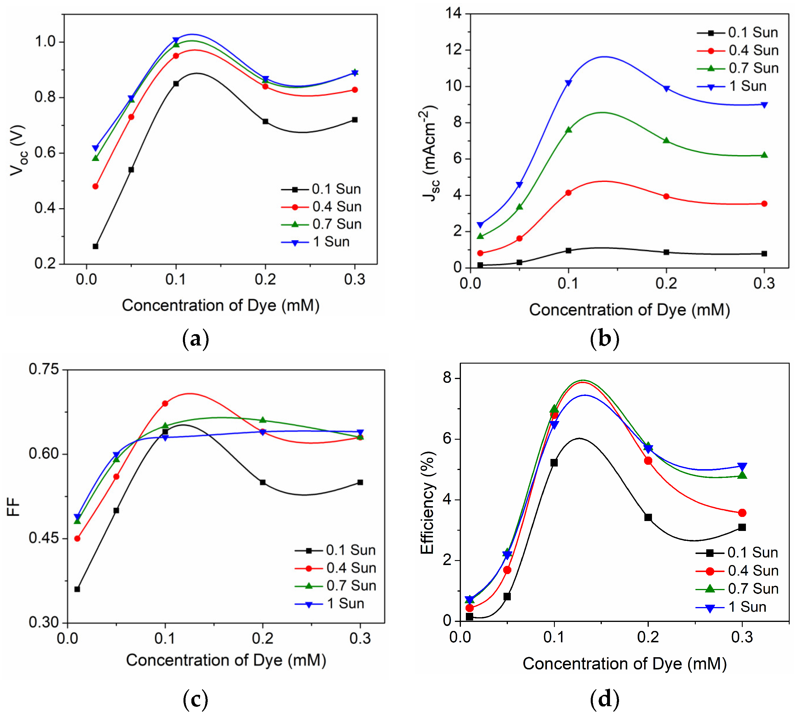
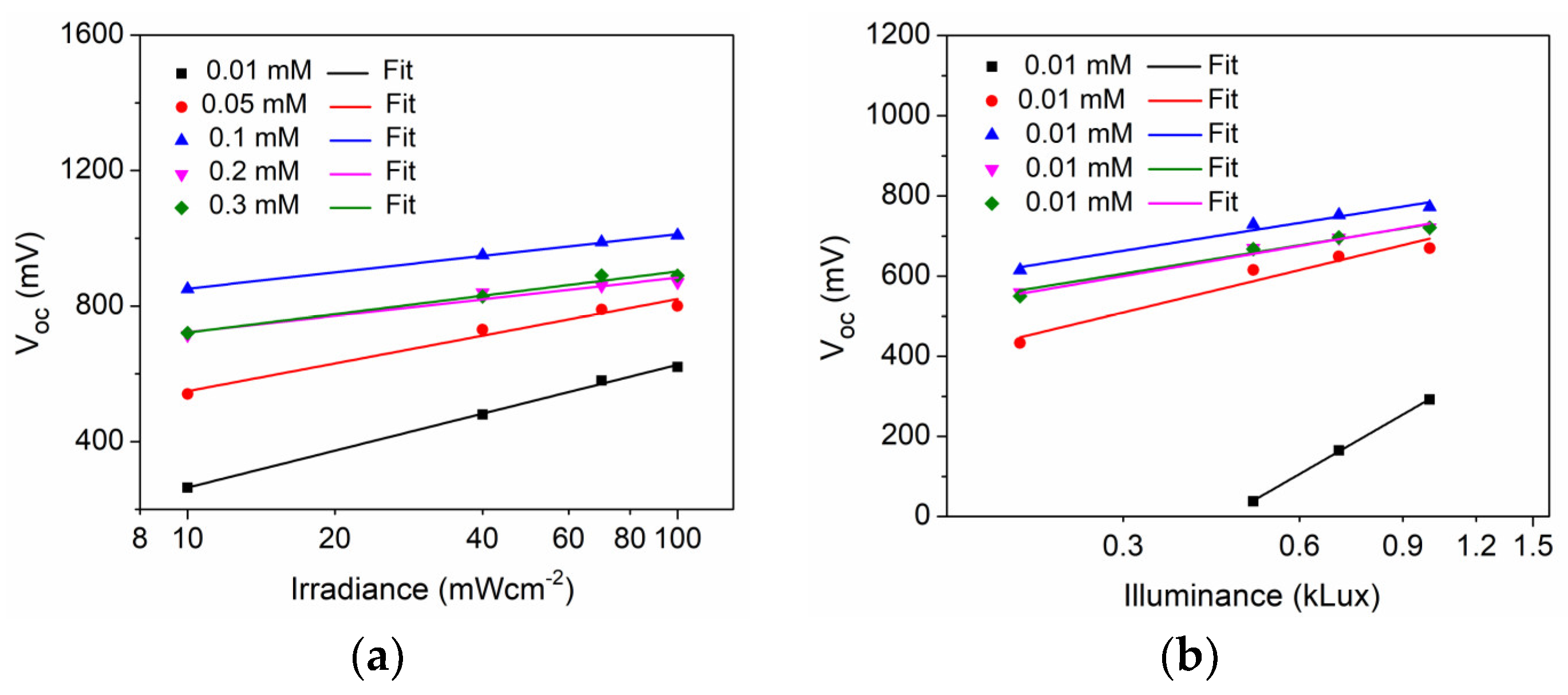
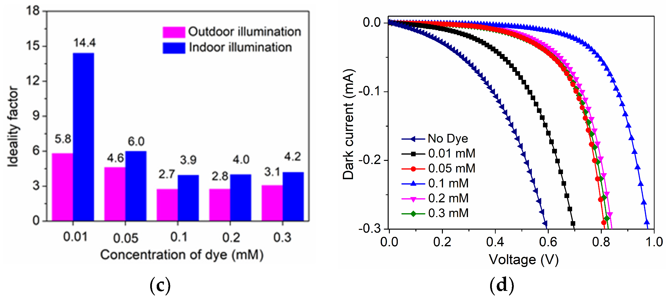
3.1. Solar Cell Characteristics under Outdoor and Indoor Light
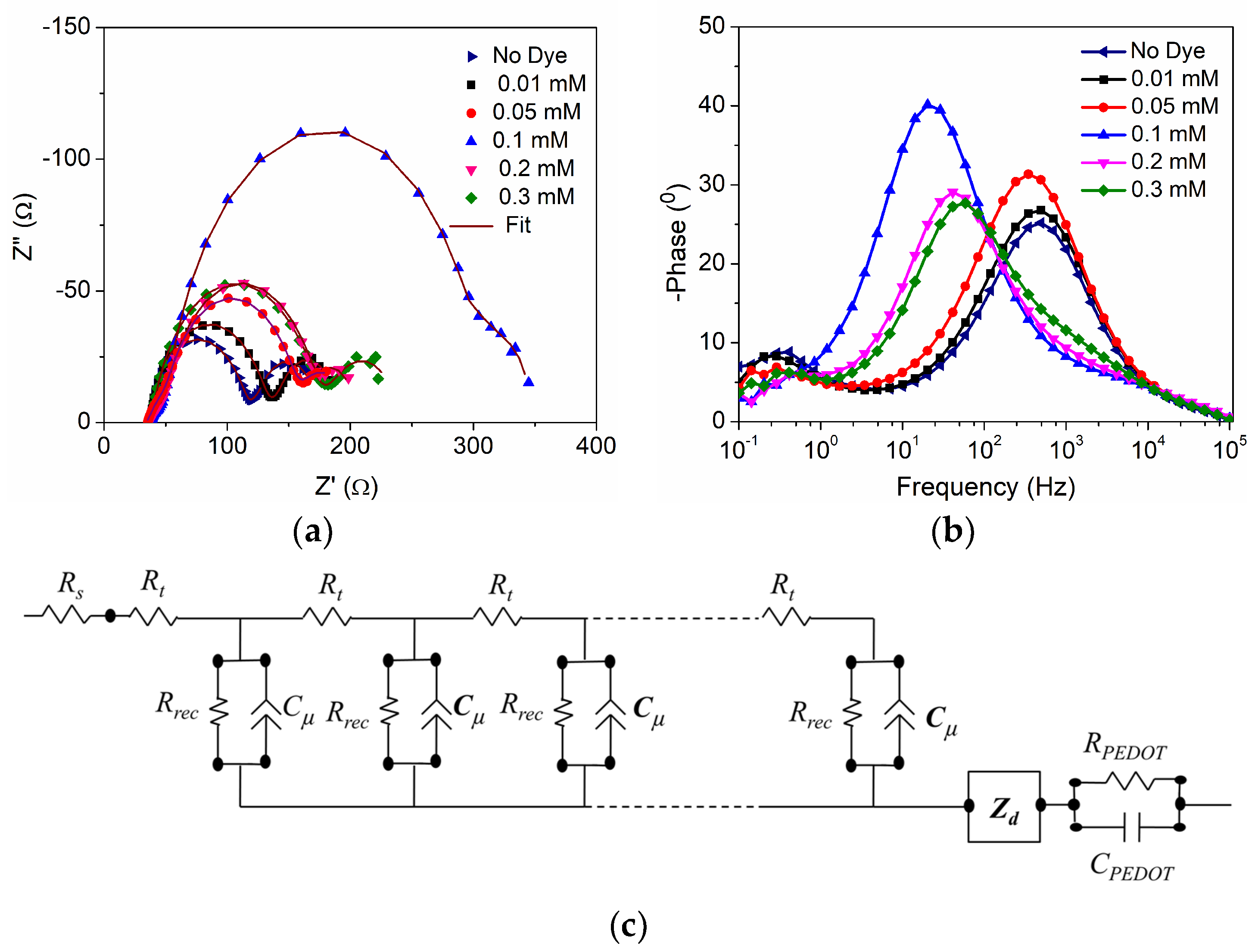
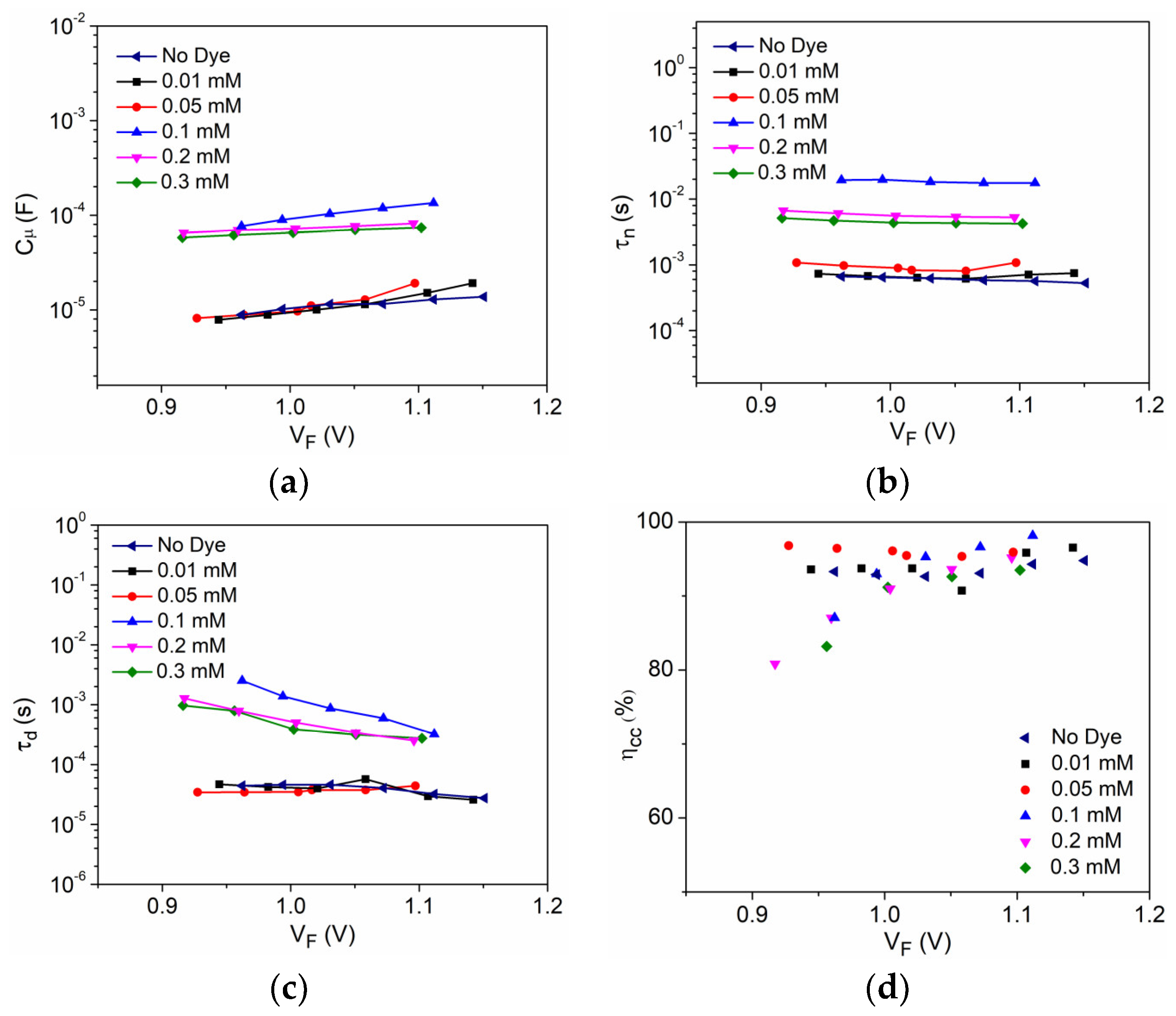
3.2. Interfacial Charge Transfer Study
4. Discussion
Supplementary Materials
Author Contributions
Funding
Data Availability Statement
Conflicts of Interest
References
- Sohani, A.; Memon, S.; Hoseinzadeh, S.; Garcia, D.A.; Schoden, F.; Detzmeier, J.; Schnatmann, A.K.; Blachowicz, T.; Schwenzfeier-Hellkamp, E. Investigating the Remanufacturing Potential of Dye-Sensitized Solar Cells. Sustainability 2022, 14, 5670. [Google Scholar] [CrossRef]
- Syed, T.H.; Wei, W. Technoeconomic Analysis of Dye Sensitized Solar Cells (DSSCs) with WS2/Carbon Composite as Counter Electrode Material. Inorganics 2022, 10, 191. [Google Scholar] [CrossRef]
- Enaganti, P.K.; Soman, S.; Devan, S.S.; Pradhan, S.C.; Srivastava, A.K.; Pearce, J.M.; Goel, S. Dye-sensitized Solar Cells as Promising Candidates for Underwater Photovoltaic Applications. Prog. Photovolt. Res. Appl. 2022, 30, 632–639. [Google Scholar] [CrossRef]
- Aslam, A.; Mehmood, U.; Arshad, M.H.; Ishfaq, A.; Zaheer, J.; Ul Haq Khan, A.; Sufyan, M. Dye-Sensitized Solar Cells (DSSCs) as a Potential Photovoltaic Technology for the Self-Powered Internet of Things (IoTs) Applications. Sol. Energy 2020, 207, 874–892. [Google Scholar] [CrossRef]
- Mariotti, N.; Bonomo, M.; Fagiolari, L.; Barbero, N.; Gerbaldi, C.; Bella, F.; Barolo, C. Recent Advances in Eco-Friendly and Cost-Effective Materials towards Sustainable Dye-Sensitized Solar Cells. Green Chem. 2020, 22, 7168–7218. [Google Scholar] [CrossRef]
- Saddow, E.; Raut, P.; Kishnani, V.; Mondal, K.; Gupta, A.; Jana, S.C. A Review on Gel Polymer Electrolytes for Dye-Sensitized Solar Cells. Micromachines 2022, 13, 680. [Google Scholar] [CrossRef]
- Kokkonen, M.; Talebi, P.; Zhou, J.; Asgari, S.; Soomro, S.A.; Elsehrawy, F.; Halme, J.; Ahmad, S.; Hagfeldt, A.; Hashmi, S.G. Advanced Research Trends in Dye-Sensitized Solar Cells. J. Mater. Chem. A 2021, 9, 10527–10545. [Google Scholar] [CrossRef]
- Zhang, D.; Stojanovic, M.; Ren, Y.; Cao, Y.; Eickemeyer, F.T.; Socie, E.; Vlachopoulos, N.; Moser, J.E.; Zakeeruddin, S.M.; Hagfeldt, A.; et al. A Molecular Photosensitizer Achieves a V Oc of 1.24 V Enabling Highly Efficient and Stable Dye-Sensitized Solar Cells with Copper(II/I)-Based Electrolyte. Nat. Commun. 2021, 12, 1777. [Google Scholar] [CrossRef]
- Michaels, H.; Rinderle, M.; Freitag, R.; Benesperi, I.; Edvinsson, T.; Socher, R.; Gagliardi, A.; Freitag, M. Dye-Sensitized Solar Cells under Ambient Light Powering Machine Learning: Towards Autonomous Smart Sensors for the Internet of Things. Chem. Sci. 2020, 11, 2895–2906. [Google Scholar] [CrossRef]
- Haridas, R.; Velore, J.; Pradhan, S.C.; Vindhyasarumi, A.; Yoosaf, K.; Soman, S.; Unni, K.N.N.; Ajayaghosh, A. Indoor Light-Harvesting Dye-Sensitized Solar Cells Surpassing 30% Efficiency without Co-Sensitizers. Mater. Adv. 2021, 2, 7773–7787. [Google Scholar] [CrossRef]
- Roy, A.; Ghosh, A.; Bhandari, S.; Selvaraj, P.; Sundaram, S.; Mallick, T.K. Color Comfort Evaluation of Dye-Sensitized Solar Cell (DSSC) Based Building-Integrated Photovoltaic (BIPV) Glazing after 2 Years of Ambient Exposure. J. Phys. Chem. C 2019, 123, 23834–23837. [Google Scholar] [CrossRef]
- Lee, H.M.; Yoon, J.H. Power Performance Analysis of a Transparent DSSC BIPV Window Based on 2 Year Measurement Data in a Full-Scale Mock-Up. Appl. Energy 2018, 225, 1013–1021. [Google Scholar] [CrossRef]
- Park, B.R.; Choi, E.J.; Choi, Y.J.; Moon, J.W. Environmental and Energy Performance Analysis of DSSC BIPV Window in Office Buildings. KIEAE J. 2020, 20, 121–128. [Google Scholar] [CrossRef]
- Kim, H.; Jo, J.; Lee, G.; Shin, M.; Lee, J.-C. Design and Analysis of a Highly Reliable Large-Area Z-Type Transparent Module for Dye-Sensitized Solar Cells. Sol. Energy 2017, 155, 585–592. [Google Scholar] [CrossRef]
- Barichello, J.; Vesce, L.; Mariani, P.; Leonardi, E.; Braglia, R.; Di Carlo, A.; Canini, A.; Reale, A. Stable Semi-Transparent Dye-Sensitized Solar Modules and Panels for Greenhouse Application. Energies 2021, 14, 6393. [Google Scholar] [CrossRef]
- Muñoz-García, A.B.; Benesperi, I.; Boschloo, G.; Concepcion, J.J.; Delcamp, J.H.; Gibson, E.A.; Meyer, G.J.; Pavone, M.; Pettersson, H.; Hagfeldt, A.; et al. Dye-Sensitized Solar Cells Strike Back. Chem. Soc. Rev. 2021, 50, 12450–12550. [Google Scholar] [CrossRef]
- Jiang, R.; Michaels, H.; Vlachopoulos, N.; Freitag, M. Beyond the Limitations of Dye-Sensitized Solar Cells. In Dye-Sensitized Solar Cells; Elsevier: Amsterdam, The Netherlands, 2019; pp. 285–323. [Google Scholar] [CrossRef]
- Yella, A.; Humphry-Baker, R.; Curchod, B.F.E.; Ashari Astani, N.; Teuscher, J.; Polander, L.E.; Mathew, S.; Moser, J.-E.; Tavernelli, I.; Rothlisberger, U.; et al. Molecular Engineering of a Fluorene Donor for Dye-Sensitized Solar Cells. Chem. Mater. 2013, 25, 2733–2739. [Google Scholar] [CrossRef]
- Sivasankaran, L.; Pradhan, S.C.; Mishra, R.K.; Soman, S.; Ajayaghosh, A. Role of Alkyl Groups Regulating Recombination and Mass Transport at Cobalt Electrolyte-Dye Interface in Dye Sensitized Solar Cells. Sol. Energy 2022, 236, 182–194. [Google Scholar] [CrossRef]
- Zhang, W.; Wu, Y.; Bahng, H.W.; Cao, Y.; Yi, C.; Saygili, Y.; Luo, J.; Liu, Y.; Kavan, L.; Moser, J.-E.; et al. Comprehensive Control of Voltage Loss Enables 11.7% Efficient Solid-State Dye-Sensitized Solar Cells. Energy Environ. Sci. 2018, 11, 1779–1787. [Google Scholar] [CrossRef]
- Gangadhar, P.S.; Jagadeesh, A.; Rajesh, M.N.; George, A.S.; Prasanthkumar, S.; Soman, S.; Giribabu, L. Role of π-Spacer in Regulating the Photovoltaic Performance of Copper Electrolyte Dye-Sensitized Solar Cells Using Triphenylimidazole Dyes. Mater. Adv. 2022, 3, 1231–1239. [Google Scholar] [CrossRef]
- Naim, W.; Novelli, V.; Nikolinakos, I.; Barbero, N.; Dzeba, I.; Grifoni, F.; Ren, Y.; Alnasser, T.; Velardo, A.; Borrelli, R.; et al. Transparent and Colorless Dye-Sensitized Solar Cells Exceeding 75% Average Visible Transmittance. JACS Au 2021, 1, 409–426. [Google Scholar] [CrossRef]
- Huaulmé, Q.; Mwalukuku, V.M.; Joly, D.; Liotier, J.; Kervella, Y.; Maldivi, P.; Narbey, S.; Oswald, F.; Riquelme, A.J.; Anta, J.A.; et al. Photochromic Dye-Sensitized Solar Cells with Light-Driven Adjustable Optical Transmission and Power Conversion Efficiency. Nat. Energy 2020, 5, 468–477. [Google Scholar] [CrossRef] [PubMed]
- Ren, Y.; Zhang, D.; Suo, J.; Cao, Y.; Eickemeyer, F.T.; Vlachopoulos, N.; Zakeeruddin, S.M.; Hagfeldt, A.; Grätzel, M. Hydroxamic Acid Pre-Adsorption Raises the Efficiency of Cosensitized Solar Cells. Nature 2022, 613, 60–65. [Google Scholar] [CrossRef]
- Michaels, H.; Benesperi, I.; Freitag, M. Challenges and Prospects of Ambient Hybrid Solar Cell Applications. Chem. Sci. 2021, 12, 5002–5015. [Google Scholar] [CrossRef]
- Freitag, M.; Boschloo, G. The Revival of Dye-Sensitized Solar Cells. Curr. Opin. Electrochem. 2017, 2, 111–119. [Google Scholar] [CrossRef]
- Freitag, M.; Teuscher, J.; Saygili, Y.; Zhang, X.; Giordano, F.; Liska, P.; Hua, J.; Zakeeruddin, S.M.; Moser, J.E.; Grätzel, M.; et al. Dye-Sensitized Solar Cells for Efficient Power Generation under Ambient Lighting. Nat. Photonics 2017, 11, 372–378. [Google Scholar] [CrossRef]
- Saygili, Y.; Söderberg, M.; Pellet, N.; Giordano, F.; Cao, Y.; Muñoz-García, A.B.; Zakeeruddin, S.M.; Vlachopoulos, N.; Pavone, M.; Boschloo, G.; et al. Copper Bipyridyl Redox Mediators for Dye-Sensitized Solar Cells with High Photovoltage. J. Am. Chem. Soc. 2016, 138, 15087–15096. [Google Scholar] [CrossRef]
- Freitag, M.; Giordano, F.; Yang, W.; Pazoki, M.; Hao, Y.; Zietz, B.; Grätzel, M.; Hagfeldt, A.; Boschloo, G. Copper Phenanthroline as a Fast and High-Performance Redox Mediator for Dye-Sensitized Solar Cells. J. Phys. Chem. C 2016, 120, 9595–9603. [Google Scholar] [CrossRef]
- Li, J.; Yang, X.; Yu, Z.; Gurzadyan, G.G.; Cheng, M.; Zhang, F.; Cong, J.; Wang, W.; Wang, H.; Li, X.; et al. Efficient Dye-Sensitized Solar Cells with [Copper(6,6′-Dimethyl-2,2′-Bipyridine)2]2+/1+ Redox Shuttle. RSC Adv. 2017, 7, 4611–4615. [Google Scholar] [CrossRef]
- Jagadeesh, A.; Veerappan, G.; Devi, P.S.; Narayanan Unni, K.N.; Soman, S. Synergetic Effect of TiO2/ZnO Bilayer Photoanodes Realizing Exceptionally High VOC for Dye-Sensitized Solar Cells under Outdoor and Indoor Illuminations. J. Mater. Chem. A 2023, 11, 14748. [Google Scholar] [CrossRef]
- Wu, H.; Wang, G.; Lei, B.X. Bulky 3D Structures of Dithienopyrrol Dye with Copper(II/I) Redox Mediator Enabling Efficient Solar Cells with an Open-Circuit Voltage of 1.13 V. ACS Appl. Energy Mater. 2022, 5, 9962–9969. [Google Scholar] [CrossRef]
- Grobelny, A.; Shen, Z.; Eickemeyer, F.T.; Antariksa, N.F.; Zapotoczny, S.; Zakeeruddin, S.M.; Grätzel, M. Molecularly Tailored Photosensitizer with an Efficiency of 13.2% for Dye-Sensitized Solar Cells. Adv. Mater. 2022, 35, 2207785. [Google Scholar] [CrossRef]
- Tanaka, E.; Michaels, H.; Freitag, M.; Robertson, N. Synergy of Co-Sensitizers in a Copper Bipyridyl Redox System for Efficient and Cost-Effective Dye-Sensitized Solar Cells in Solar and Ambient Light. J. Mater. Chem. A 2020, 8, 1279–1287. [Google Scholar] [CrossRef]
- Bai, Y.; Yu, Q.; Cai, N.; Wang, Y.; Zhang, M.; Wang, P. High-Efficiency Organic Dye-Sensitized Mesoscopic Solar Cells with a Copper Redox Shuttle. Chem. Commun. 2011, 47, 4376–4378. [Google Scholar] [CrossRef]
- Tang, X.; Wang, Y.; Cao, G. Effect of the Adsorbed Concentration of Dye on Charge Recombination in Dye-Sensitized Solar Cells. J. Electroanal. Chem. 2013, 694, 6–11. [Google Scholar] [CrossRef]
- Pazoki, M.; Lohse, P.W.; Taghavinia, N.; Hagfeldt, A.; Boschloo, G. The Effect of Dye Coverage on the Performance of Dye-Sensitized Solar Cells with a Cobalt-Based Electrolyte. Phys. Chem. Chem. Phys. 2014, 16, 8503. [Google Scholar] [CrossRef] [PubMed]
- Pradhan, S.C.; Soman, S. Effect of Thickness on Charge Transfer Properties of Conductive Polymer Based PEDOT Counter Electrodes in DSSC. Results Surf. Interfaces 2021, 5, 100030–100035. [Google Scholar] [CrossRef]
- Ellis, H.; Vlachopoulos, N.; Häggman, L.; Perruchot, C.; Jouini, M.; Boschloo, G.; Hagfeldt, A. PEDOT Counter Electrodes for Dye-Sensitized Solar Cells Prepared by Aqueous Micellar Electrodeposition. Electrochim. Acta 2013, 107, 45–51. [Google Scholar] [CrossRef]
- Soman, S.; Pradhan, S.C.; Yoosuf, M.; Vinayak, M.V.; Lingamoorthy, S.; Gopidas, K.R. Probing Recombination Mechanism and Realization of Marcus Normal Region Behavior in DSSCs Employing Cobalt Electrolytes and Triphenylamine Dyes. J. Phys. Chem. C 2018, 122, 14113–14127. [Google Scholar] [CrossRef]
- Feldt, S.M.; Gibson, E.A.; Gabrielsson, E.; Sun, L.; Boschloo, G.; Hagfeldt, A. Design of Organic Dyes and Cobalt Polypyridine Redox Mediators for High-Efficiency Dye-Sensitized Solar Cells. J. Am. Chem. Soc. 2010, 132, 16714–16724. [Google Scholar] [CrossRef] [PubMed]
- Dryza, V.; Bieske, E.J. Does the Triphenylamine-Based D35 Dye Sensitizer Form Aggregates on Metal-Oxide Surfaces? J. Photochem. Photobiol. A Chem. 2015, 302, 35–41. [Google Scholar] [CrossRef]
- Velore, J.; Chandra Pradhan, S.; Hamann, T.W.; Hagfeldt, A.; Unni, K.N.N.; Soman, S. Understanding Mass Transport in Copper Electrolyte-Based Dye-Sensitized Solar Cells. ACS Appl. Energy Mater. 2022, 5, 2647–2654. [Google Scholar] [CrossRef]
- Pradhan, S.C.; Velore, J.; Hagfeldt, A.; Soman, S. Probing Photovoltaic Performance in Copper Electrolyte Dye-Sensitized Solar Cells of Variable TiO 2 Particle Size Using Comprehensive Interfacial Analysis. J. Mater. Chem. C 2022, 10, 3929–3936. [Google Scholar] [CrossRef]
- Salvador, P.; Hidalgo, M.G.; Zaban, A.; Bisquert, J. Illumination Intensity Dependence of the Photovoltage in Nanostructured TiO2 Dye-Sensitized Solar Cells. J. Phys. Chem. B 2005, 109, 15915–15926. [Google Scholar] [CrossRef] [PubMed]
- Bisquert, J.; Mora-Seró, I. Simulation of Steady-State Characteristics of Dye-Sensitized Solar Cells and the Interpretation of the Diffusion Length. J. Phys. Chem. Lett. 2010, 1, 450–456. [Google Scholar] [CrossRef]
- Pradhan, S.C.; Hagfeldt, A.; Soman, S. Resurgence of DSCs with Copper Electrolyte: A Detailed Investigation of Interfacial Charge Dynamics with Cobalt and Iodine Based Electrolytes. J. Mater. Chem. A 2018, 6, 22204–22214. [Google Scholar] [CrossRef]
- Bisquert, J.; Zaban, A.; Greenshtein, M.; Mora-Seró, I. Determination of Rate Constants for Charge Transfer and the Distribution of Semiconductor and Electrolyte Electronic Energy Levels in Dye-Sensitized Solar Cells by Open-Circuit Photovoltage Decay Method. J. Am. Chem. Soc. 2004, 126, 13550–13559. [Google Scholar] [CrossRef]
- Bisquert, J.; Zaban, A.; Salvador, P. Analysis of the Mechanisms of Electron Recombination in Nanoporous TiO2 Dye-Sensitized Solar Cells. Nonequilibrium Steady-State Statistics and Interfacial Electron Transfer via Surface States. J. Phys. Chem. B 2002, 106, 8774–8782. [Google Scholar] [CrossRef]
- Fabregat-Santiago, F.; Garcia-Belmonte, G.; Mora-Seró, I.; Bisquert, J. Characterization of Nanostructured Hybrid and Organic Solar Cells by Impedance Spectroscopy. Phys. Chem. Chem. Phys. 2011, 13, 9083–9118. [Google Scholar] [CrossRef]
- Bisquert, J.; Fabregat-santiago, F.; Mora-Seró, I.; Garcia-Belmonte, G.; Giménez, S. Electron Lifetime in Dye-Sensitized Solar Cells: Theory and Interpretation of Measurements. J. Phys. Chem. C 2009, 113, 17278–17290. [Google Scholar] [CrossRef]
- Nazeeruddin, M.K.; Humphry-Baker, R.; Liska, P.; Grätzel, M. Investigation of Sensitizer Adsorption and the Influence of Protons on Current and Voltage of a Dye-Sensitized Nanocrystalline TiO2 Solar Cell. J. Phys. Chem. B 2003, 107, 8981–8987. [Google Scholar] [CrossRef]


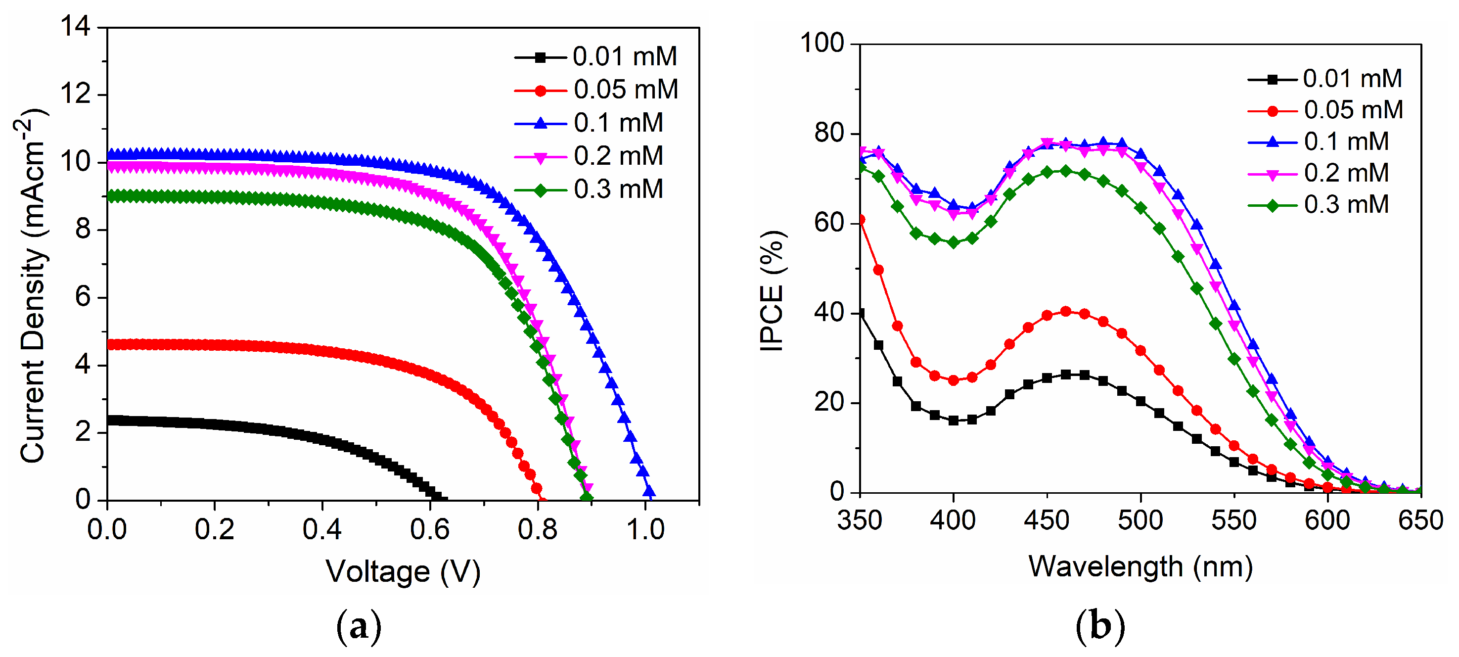
| D35 Concentration (mM) | Voc (mV) | Jsc (mAcm−2) | FF | η (%) |
|---|---|---|---|---|
| 0.01 | 622 ± 2 | 2.40 ± 0.48 | 0.49 ± 0.02 | 0.73 ± 0.12 |
| 0.05 | 803 ± 3 | 4.62 ± 0.37 | 0.60 ± 0.01 | 2.22 ± 0.18 |
| 0.1 | 1002 ± 3 | 10.22 ± 0.25 | 0.63 ± 0.01 | 6.50 ± 0.25 |
| 0.2 | 898 ± 4 | 9.91 ± 0.28 | 0.64 ± 0.03 | 5.70 ± 0.26 |
| 0.3 | 895 ± 6 | 9.09 ± 0.27 | 0.64 ± 0.02 | 5.12 ± 0.21 |
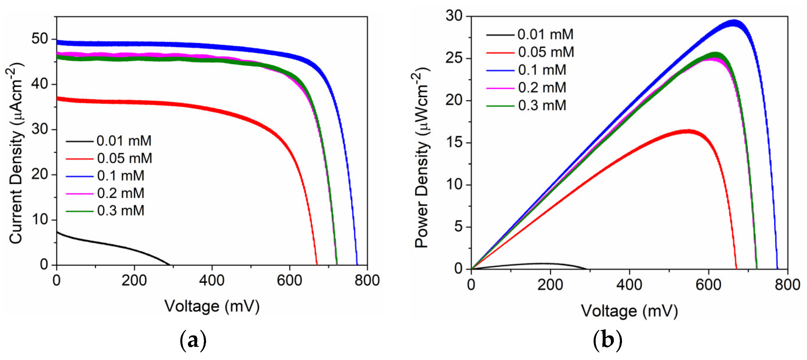
| D35 Concentration (mM) | Voc (mV) | Jsc (µAcm−2) | FF | η (%) |
|---|---|---|---|---|
| 0.01 | 292 ± 6 | 7.4 ± 0.8 | 0.32 ± 0.02 | 2.4 ± 0.22 |
| 0.05 | 670 ± 2 | 37 ± 0.9 | 0.66 ± 0.03 | 5.84 ± 0.13 |
| 0.1 | 773± 3 | 48.8 ± 0.9 | 0.78 ± 0.02 | 10.48 ± 0.30 |
| 0.2 | 721± 2 | 46.8 ± 0.6 | 0.76 ± 0.01 | 9.17 ± 0.12 |
| 0.3 | 721± 2 | 46.4 ± 0.2 | 0.77 ± 0.08 | 9.09 ± 0.21 |
Disclaimer/Publisher’s Note: The statements, opinions and data contained in all publications are solely those of the individual author(s) and contributor(s) and not of MDPI and/or the editor(s). MDPI and/or the editor(s) disclaim responsibility for any injury to people or property resulting from any ideas, methods, instructions or products referred to in the content. |
© 2023 by the authors. Licensee MDPI, Basel, Switzerland. This article is an open access article distributed under the terms and conditions of the Creative Commons Attribution (CC BY) license (https://creativecommons.org/licenses/by/4.0/).
Share and Cite
Pradhan, S.C.; Velore, J.; Meethal, S.M.; Soman, S. Fundamental Understanding of Dye Coverage and Performance in Dye-Sensitized Solar Cells Using Copper Electrolyte. Energies 2023, 16, 6913. https://doi.org/10.3390/en16196913
Pradhan SC, Velore J, Meethal SM, Soman S. Fundamental Understanding of Dye Coverage and Performance in Dye-Sensitized Solar Cells Using Copper Electrolyte. Energies. 2023; 16(19):6913. https://doi.org/10.3390/en16196913
Chicago/Turabian StylePradhan, Sourava Chandra, Jayadev Velore, Sruthi Meledath Meethal, and Suraj Soman. 2023. "Fundamental Understanding of Dye Coverage and Performance in Dye-Sensitized Solar Cells Using Copper Electrolyte" Energies 16, no. 19: 6913. https://doi.org/10.3390/en16196913