Review

A Comprehensive Review of Distributed MPPT for Grid-Tied PV Systems at the Sub-Module Level

School of Engineering, Lancaster University, Lancaster LA1 4YR, UK
*
Author to whom correspondence should be addressed.
Energies 2023, 16(14), 5468; https://doi.org/10.3390/en16145468
Submission received: 15 June 2023 / Revised: 15 July 2023 / Accepted: 17 July 2023 / Published: 19 July 2023
(This article belongs to the Collection Renewable Energy and Energy Storage Systems)

Abstract

:
Energy crises and the growth of the energy demand have increased the interest in utilizing unconventional power sources. Thus, renewable energy sources have become a topic of interest to mitigate rising energy concerns and cope with increased electricity demand. With remarkable merits including cleanness and abundance, photovoltaic (PV) solar energy systems are a key to solving these issues. The employed inverters should effectively utilize the maximum available power from the PV solar system and transfer this power to the utility grid without posing any further limitations. However, the unequal power generation of different PV systems caused by partial shading (PS) and other PV panel degradation factors leads to a reduction in generation capacity. One of the relatively new solutions to mitigate the mismatch concerns between the PV modules and sub-modules is to extract the maximum power of each sub-module individually. The main objective of this paper is to present a comprehensive review of such PV grid-connected inverters topologies associated with sub-module connection and control. It will classify the PV grid-tied inverters in accordance with the level where the maximum power point tracking (MPPT) system is implemented. A special focus has been placed on sub-module microinverters (MI) in terms of circuit topologies, conversion efficiency, and controller design. This paper provides a comprehensive analysis of employing the distributed MPPT (DMPPT) approach to maximize the power generation of PV systems by mitigating the mismatch issues inside the PV module. The circuit topology, PV system configuration, and MPPT algorithms used for applying DMPPT solutions in PV SMs are discussed in detail in this study.

1. Introduction

Nowadays, the electrical grid has evolved to become a mixture of several power-generating resources and photovoltaic (PV) generators are an important key player in this integrated system [1,2]. Extracting the maximum power from the PV system and studying the possible limitations of injecting electrical energy into the grid is the key design goal of grid-connected PV systems [3]. Thus, tracking the maximum power from the PV systems during different irradiation levels, shading conditions, and low conversion efficiency is one of the main design concerns [3,4]. Several standards are used by different organizations to prevent overhead complications on the utility grid [5,6,7]. For example, the power quality, reactive power control, and islanding operation are some of the main problems that pose severe issues for the distribution network. Therefore, the employed PV inverter should be designed so it is able to operate at a unity power factor, improve the power quality, and have a fast dynamic response. Operating at a unity power factor is important in order to reduce the total current through the cables and improve the reactive power content in the grid [8].
From the power quality perspective, the major grid codes state that the total harmonic distortion (THD) of the output current must not exceed the 5% limit [9]. The THD is subject to increase by either the low- or the high-order current harmonics [10]. To reduce the high order current harmonics, the employed inverter needs to operate at a high switching frequency or to have big filtering elements in terms of inductors and capacitors. Increasing the switching frequency puts more burden on the switching elements and may increase the switching losses, while making the filter bigger will increase the size and volume of the system [11]. On the other hand, the low order harmonics can be eliminated by the suitable control loops acting as harmonic compensators [12]. Figure 1 shows experimental results for inverters producing outputs with high and low-order harmonic currents.
The fast dynamic response of the employed inverter will enable the system to recover from faults swiftly, increasing the reliability against faults [13]. In addition, the design must consider the islanding situation to protect both the users and equipment. The conventional islanding method often monitors the grid parameters and takes preventive actions accordingly [14]. Figure 2 shows another experimental test for an inverter experiencing faults when its controllers have slow and fast dynamic responses.
Categorizing the PV systems can be a helpful method for understanding the different PV system architectures and the purpose of each design [14]. This might help researchers in this field to comprehend the state of the art of grid-tied PV systems. The inverters and MI are designed to convert the direct current (DC) to alternating current (AC) in both large-scale PV plants and small PV applications, and it plays a crucial role in enhancing the PV system reliability and improving overall efficiency [14]. Therefore, PV-interfaced systems research is focused on optimizing the existing PV systems’ topologies to reduce PV system costs and achieve better system performance [15,16,17,18,19,20]. The PV system’s design usually comes in one of four common topologies according to the PV module arrangements and PV system requirements. Namely, these topologies are centralized inverter PV plants, string inverters, multi-string inverter PV, and PV module MI PV systems [21].
The conventional classification of PV systems is mainly based on the power capacity of the PV applications and projects [21]. Thus, the three main categories of a grid-connected PV system are large-scale PV plants, medium-scale PV projects, and small-scale PV applications. The small-scale application starts from a few kW to up to 50 kW, while medium-scale project capacity can reach up to 1 MW. A PV system with a power capacity of more than 1 MW can be considered a large-scale project [14,22].
Classifying the grid-tied PV systems based on the voltage level at the point of common coupling (PCC) is another approach to categorizing grid-connected PV systems. Low voltage grid-connected PV systems include both small PV applications and some medium-scale PV projects where PV systems are installed close to the end users. Large PV plants are directly connected to a 20 kV voltage grid or more in high-voltage grid-tied PV systems [23]. One main objective of PV power converter devices is harvesting and exporting the maximum available power from the PV system to the utility grid. Therefore, designing and optimizing the maximum power point tracking strategies can significantly improve the PV system efficiency and enable obtaining the full available PV power [14,24].
PV inverters are designed and controlled to operate on their maximum power point (MPP) using a maximum power point tracking (MPPT) controller [25,26,27,28,29,30,31]. Operating at the MPP of the PV system is usually related to the scale of the PV system. This means that when the inverter or MI is connected to a number of the PV modules, the tracking process becomes swift and more accurate, which can improve the efficiency and reduce the overhead on the PV system controllers [32]. The grid-tied inverters are an essential part of renewable energy interfaced systems that link the different types of renewable resource and energy storage systems to the utility grid. Therefore, optimizing the grid-connected inverters can significantly contribute to reducing the investment and operation cost of the PV system [33].
The electrical grids need support from the connected distributed generators, and their power generation security can be enhanced if the solar power plants can export the power directly to the medium- or high-voltage networks without limiting grid stability [9,34]. Controlling the active power of the PV system’s current can increase energy yield and enhance PV system performance, which can improve grid-side performance. However, different power consumption patterns caused by changing the voltage and frequency of the utility grid can negatively affect grid stability. Overcoming this issue will be based on regulating the voltage and frequency during the design of the controllers of the grid-tied PV systems [34]. The stability of the utility grid can be improved if proper active and reactive power controllers are used, and common grid-related concerns, especially voltage sags, can be solved [34,35].
The grid-tied inverters can be interfaced with three-phase and single-phase power systems according to the PV project size [35]. In the three-phase power system, the step-up transformers are used to boost the output voltage and meet the grid-side voltage requirements [36,37,38]. Centralized inverters are usually used in three-phase power systems to link large-scale PV plants to the utility grid [39]. The centralized inverter technology is usually used in three-phase power systems and it might be the most traditional in PV systems; it has been used for many years because of its large-scale conversion ability. On the other hand, in a single-phase power system, the small PV applications are often interfaced with the distribution network, and distributed MPPT inverters are used [40].
Distributed MPPT inverters have been proposed to increase the power harvesting from PV systems. They can significantly increase power generation under low irradiation levels. Also, distributing the MPPT can improve the scalability of the PV system without introducing a significant disturbance to the utility grid [33,40].
The unbalanced power generation of PV modules due to different environmental conditions is one of the significant issues in centralized PV systems and it significantly reduces power generation in PV systems [41,42]. One main cause of unbalanced power generation between PV components is partial shading due to buildings, clouds, and trees. This can lead to mismatch problems in PV power systems. The mismatch problem can negatively affect conversion efficiency, since the PV system current will be limited by the PV module with the lowest output current [43].
Centralized grid-tied inverters might not be able to identify the power generated by each parallel sting under a partial shading effect and the overall power generation of the PV system will be reduced [42]. The bypass diode is commonly integrated with the PV SM to minimize the effect of partial shading; however, it can cause multiple peak power points. In such a scenario, the MPPT algorithm might only be able to track the average maximum power. However, the average output power can be lower than the sum of the maximum power of the PV modules [44].
The DMPPT technique has been used to mitigate the mismatch issue between PV components and increase the energy yield of the PV system [45,46,47]. Although the DMPPT strategy requires a more complex controlling process, it can improve the reliability of the PV system and mitigate the mismatch problem [46].
Several issues can lead to the different current generations of PV components, including external factors such as different PV panel orientations and partial shading. Also, interior features such as manufacturing tolerance and aging might unbalance the power generation of PV strings [44]. Also, faulty PV components can limit the PV string’s current, which will reduce the current generated by other PV components in the series connection. Thus, processing the power generation of each PV component can mitigate the negative effect of the faulty PV component on others in the series connection [45].
Conventional PV systems have several severe problems that limit PV power generation and adversely affect PV system performance. Power losses due to mismatch issues, partial shading, and ground-associated faults can be the major issues. Thus, optimizing the typical PV system is usually based on tackling these concerns. One proper solution to overcome the mismatch concerns and partial shading effect is employing MPPT at a finer level. This review paper discusses the state of the art of distributing MPPT technology on grid-connected PV systems. It is focused on applying the DMPPT approach at the PV SM level [48].
One main objective of classifying the grid-connected inverter is to understand the latest trend in this technology and help researchers to choose the optimization opportunities effectively. Organizing the grid-tied inverters according to where MPPT is applied can be a proper categorization strategy. In this review paper, the grid-connected inverters are classified according to the level where the MPPT is applied. The grid-tied inverters can be grouped into two main groups according to the MPPT function, centralized MPPT, and DMPPT. This work can be a helpful tool to understand different types of grid-connected PV systems and the purpose of each PV system topology.
Some review papers have discussed employing the DMMPT approach to effectively increase the power harvesting of PV systems [49]. Others discuss the negative effect of partial shading on a group of PV cells [50]. However, none of them have deep discussions about applying the DMPPT technique at the PV SM level. Thus, the lack of information about employing DMPPT led to this review paper. Although studies on [51] present some issues related to DMPPT on the PV SM level, there is still an absence of discussion about MPPT techniques used at the PV SM level. This paper reviews common power converter topologies and MPPT techniques that have been used to employ the DMPPT systems at the PV SM level.
It reviews the power electronic converter topologies used for grid-tied PV systems, with a specific focus on low-voltage-level modular PV applications. The paper will categorize the grid-connected PV systems according to where MPPT is employed and will explain the distributed MPPT strategy which has been used as a viable solution to overcome the unbalanced power generation under the partial shading effect. A detailed explanation of grid-tied PV inverter topologies including merits, limitations, and technical issues is provided in Section 2. An important consideration of PV SM DMPPT architectures and a specific review of different MPPT algorithms is presented in Section 3. Detailed discussion about the finding of this review and proposed recommendations are considered in Section 4. Section 5 discusses the present associated challenges and gives direction for related future work. Finally, Section 6 concludes the outcomes of this review study.

2. Grid-Connected PV Inverter Topologies

Grid-tied DC–AC inverters have been devised to enable pumping up the generated power from PV systems into utility grid companies. To effectively send PV power to the grid, several standards should be fulfilled by the grid-tied DC–AC inverter, including maintaining power quality, decoupling the arising AC current components at the input side, and consideration of the islanding situation [52]. The DC–AC inverter is an essential part of grid-connected PV systems and hence reducing the cost per inverter watt can significantly minimize the installation cost of the PV generators. Therefore, many researchers focus on innovating optimized and cost-effective inverters [53,54,55]. The employed inverter can operate as a voltage or current source inverter [56]. For voltage source inverters (VSIs), the input DC voltage will be chopped by input switches operating and controlled by a pulse-width-modulation (PWM) scheme, converted to the output side by the output switches and then filtered by inductors.
The main issue with VSIs is that their input currents are discontinuous, which requires large capacitors at the input side to smooth the PV module current [57]. Installing large capacitors at the input side (output of the PV modules) is not favored as it can affect the system’s reliability negatively. Current source inverters (CSIs) can generate continuous currents at the input side first, then chop the currents using the set of PWM switches, and then filter this current using a capacitor [58]. CSIs do not need large filtering capacitors at the input side and therefore are favorable to be employed as PV inverters.
However, their control system is usually more complicated than that of VSIs and needs careful parameter tuning. This is because the CSI requires at least an additional input stage where the current is generated by the action of the input switches with the inductors. This means that the output current and voltage are not generated directly from the input side, which appears as a right-hand plane (RHP) zero in the frequency domain analysis of the inverter. Figure 3 shows the basic structures of a VSI and CSI.
The connection of the PV modules or panels to the inverters is important in selecting the suitable inverter system. As shown in Figure 4, there are different possible connection technologies and they will be presented briefly in the next subsections.

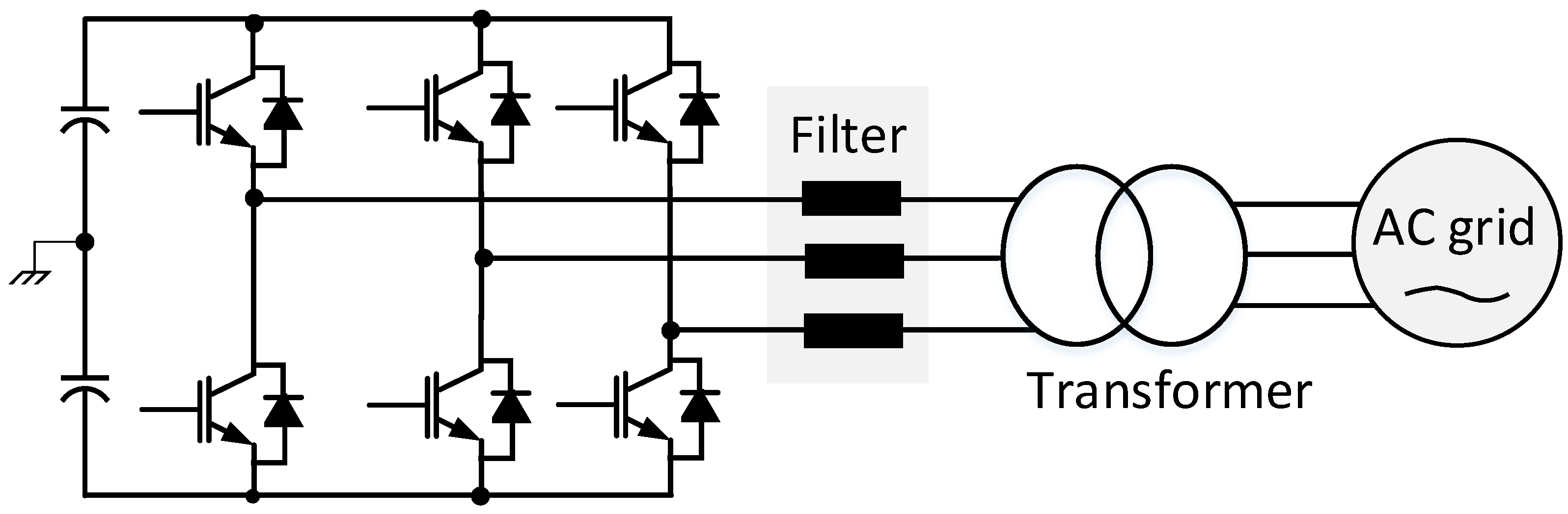
2.1. Grid-Tied Central Inverter

Grid-connected central inverters might be the oldest technology used for both grid-tied and standalone PV systems. The essential objective of the central inverters is to link high-powered PV plants with a utility grid. The central inverter technology is a combination of series and parallel connections of PV modules [59]. The series connection is called a string, and it is used to generate sufficient output voltage according to the utility grid needs. Thus, the central inverter does not necessarily require further voltage amplification during the circuit design stage. Each PV string of the central inverter is connected in parallel via string diodes to prevent the reverse current flowing from other strings in the PV array. The parallel connection in central inverters is often used to obtain PV projects’ high power requirements [60,61]. One common concern about the centralized inverter is the self-partial shading of the PV system when some of the modules cause shading of others. This issue can be solved by varying the distance from the PV strings [62].
The MPPT control of the grid-tied central inverter is usually operated at the PV plant level, which reduces the MPPT controllers’ complexity. However, central inverters have several severe limitations, and one of the main concerns of this technology is the mismatch losses due to the different power generation from the PV modules during partial shading conditions [63,64]. Central inverters often use high-voltage cables to link the PV arrays with the utility grid, significantly increasing the installation cost. Also, the scalability of the PV design is limited in this technology, thus increasing the power production might not be achieved. The string diodes that are used in central inverters have an internal loss that reduces the overall efficiency of the PV plants. A central inverter malfunction might lead to a loss generated from the PV array [65].
The breakdown of a central large-scale inverter can stop the entire PV system from working, cause loss of PV power generation, and can pose several limitations to grid utility. This concern can be mitigated by using multicentral PV inverters [66,67]. Multicentral inverter topologies can improve the reliability of a large PV power plant and apply the MPPT at a sub-array level, which might mitigate the mismatch issues. The multicentral PV inverter technology aims to group the large PV array system into subarrays where each parallel connection is linked to an individual inverter. This technology is often preferred for medium and large PV plants where power generation exceeds 0.5 MW [68]. The multicentral PV inverters are commonly connected in parallel to obtain the maximum power from the subarrays and maintain the reliability of the PV system in the case of inverter malfunction. Figure 4a illustrates the single central PV inverter topology and Figure 4b shows the multicentral PV inverter connection.
A basic example of central inverters is the three-phase VSI which is shown in Figure 5. Because the full power is handled through the six semiconductor switches, the failure of any switch will result in the full shutdown of the PV system. The switches can be affected by overvoltage or overcurrent from the PV modules as well as the high temperature which is expected in this application. This might increase power losses and adversely affect the efficiency of the PV system. Distributing the MPPT at a lower level can mitigate this issue and improve PV energy harvesting.
The central inverter is usually a large inverter used to convert the high DC power from the PV array to AC power. The system topology might come in one of two different topologies in terms of power pressing, single-stage central inverter, and dual-stage central inverter. Three-phase converters can offer some merits compared to single-phase full-bridge converters, including reducing the size of the high-frequency transformer while maintaining the switching frequency, reduction in the size of filter components, and better conversion efficiency [69]. The DC–AC central inverter is often connected to medium- and high-voltage power systems because this technology is designed to generate high-rated power, which is more suitable to interface with a three-phase system. One of the main objectives of using three-phase grid-tied central inverters is their capability to mitigate the effect of THD and improve transient performance, leading to higher efficiency [70]. On the other hand, single-phase inverters will be required if the scale of the PV system is lower than 10 kW, which is usually the limit of residential PV systems. The main issue with single-phase systems is that they have power components pulsating at twice the grid’s frequency. This pulsating power will cause the input current of the inverter, which is the output current of the PV modules, to have both DC and AC components. The AC current component will cause the output PV power to be fluctuating around the MPP and hence the maximum power will not be obtained; current-voltage and power-voltage curves are illustrated in Figure 6. Therefore, the AC component of the inverter’s input current has to be eliminated using either a hardware filter or a complete control algorithm [12,48].

2.2. Grid-Tied Distributed Inverter

The DMPPT is a strategy used to maximize PV energy harvesting and improve PV system performance [45,47]. The DMPPT approach can be implemented at different PV system levels from the PV array level to the PV cell level [46]. The maximum energy of PV systems can be captured when the PV modules operate at their MPP, as shown in Figure 6. Different tracking algorithms have been used to track and capture maximum power from PV systems [28,29,30]. The input voltage of the PV system should have relatively small ripples to enable the tracking algorithm to operate successfully. To maintain the tracking algorithm accuracy at more than 98%, the voltage ripple from the PV input side should be less than 8.5% [45].

2.2.1. PV String-Level Inverter

The string inverter technology in Figure 4c is an updated version of the conventional central inverter topology [4]. Each string is built by connecting a series of PV modules and the resultant connection is linked to the DC/AC inverter. Some string inverters can meet the voltage requirements of the grid side and hence DC–DC step-up converter will not be needed. However, some other systems will require DC–DC boost converters on the input side or boosting transformers on the output side to step up the output voltage in order to reach the voltage level of the utility grid [71]. Grid-tied string inverters can mitigate some issues presented in central inverters [32]. For example, the power losses due to using the string diode to eliminate reverse current from other strings of the parallel connection are eliminated, which helps to improve the overall efficiency of the PV system. Furthermore, the mismatch issue between the PV system strings caused by different current generations is reduced, and each PV string will operate at an individual MPPT [40]. Compared with central inverters, the robustness of the PV system can be enhanced using string inverters because failure of one string does not stop the entire PV system from working. Because the total power is shared by several inverters, the current ratings of the employed semiconductor devices can be reduced in comparison with the central inverter topology, which will result in improving the efficiency and enhancing the reliability [49]. Figure 4c illustrates the circuit topology of the string inverters.

2.2.2. PV Module-Level Inverter

The conventional residential PV system topology is usually based on cascading the PV panel to reach the grid-side voltage level. The maximum power can be harvested by operating each PV panel at its total MPP, which will be the global point for the combined panel [72]. Nevertheless, residential PV applications are sensitive to the mismatch problem between the PV panels because it adversely reduces PV power generation [4]. One proposed solution to mitigate the mismatch problem between PV panels is to add a parallel diode with each PV panel, which can reduce the negative voltage polarity of faulty PV modules caused by full or partial shading [73]. However, power generated from the affected PV panel will be lost in this case. In the PV module level inverter system, each separate PV module in the panel will have its dedicated inverter and controller to harvest the maximum energy and operate the PV modules at their local MPPs. Accordingly, each PV module will be sold with the MI, which can be a single-stage or a double-stage inverter [74]. Because the MIs are designed at the module level, the employed semiconductors can have lower voltage and current ratings, which will increase the total efficiency. Also, the reliability of the total system will be improved during faults in one or more MI because the rest of the system will function normally.
Although it can be predicted that the cost of this system will be higher than those with the central inverter structure, the study in [75] shows that the price can be lower on some occasions. Moreover, this system provides a greater degree of freedom in terms of reactive power generation and grid support in general. In this context, the DC–DC optimizer has been proposed to obtain each PV module’s power and meet the end users’ local demands. The DC–DC optimizer can be applied in two common topologies: series connected to a DC–DC optimizer and parallel connected a DC–DC optimizer [76]. The cascaded DC–DC optimizer architecture can provide better conversion efficiency compared with parallel connected optimizers [77]. Figure 4d illustrates module-integrated DC–AC MI.

2.2.3. PV Sub-Module-Level DMPPT

This is a new approach to applying DMPPT in residential PV systems based on the PV sub-panel level [23,71]. The integrated distributed power electronics enable capturing the maximum power from each sub-panel inside a single PV module. Employing this strategy not only reduces the current and voltage mismatch but also can increase the energy captured by up to 20% by distributing MPPT at the finer level [71]. Commercial PV panels are usually grouped into three or four groups according to the manufacturing company; also the PV panel commonly comes with a PV junction box that contains the electronic parts of the PV panel [23]. Figure 7 illustrates the typical 72-PV-cell panel with its PV junction box.
The revolution of the grid-connected PV inverter is presented in Table 1. The past approach was based on conventional central inverter technology. A centralized inverter is commonly used with three-phase power systems. The MPPT system is implemented at the PV array level and only one MPPT is employed. The multi-string inverter technology comes after the central PV inverter. In such technology, the PV array is grouped into multi-strings. The MPPT is applied to a lower level and both three- and single-phase power systems might be interfaced. In the PV string inverter, DMPPT is implemented at the PV string level and a single-phase system is commonly used in this technology. The present study focuses on technologies consisting of a PV module and a PV SM inverter. Employing DMPPT at this level can significantly maximize power harvesting since the MPPT system is implemented at a finer level.

3. PV SM DMPPT Architectures
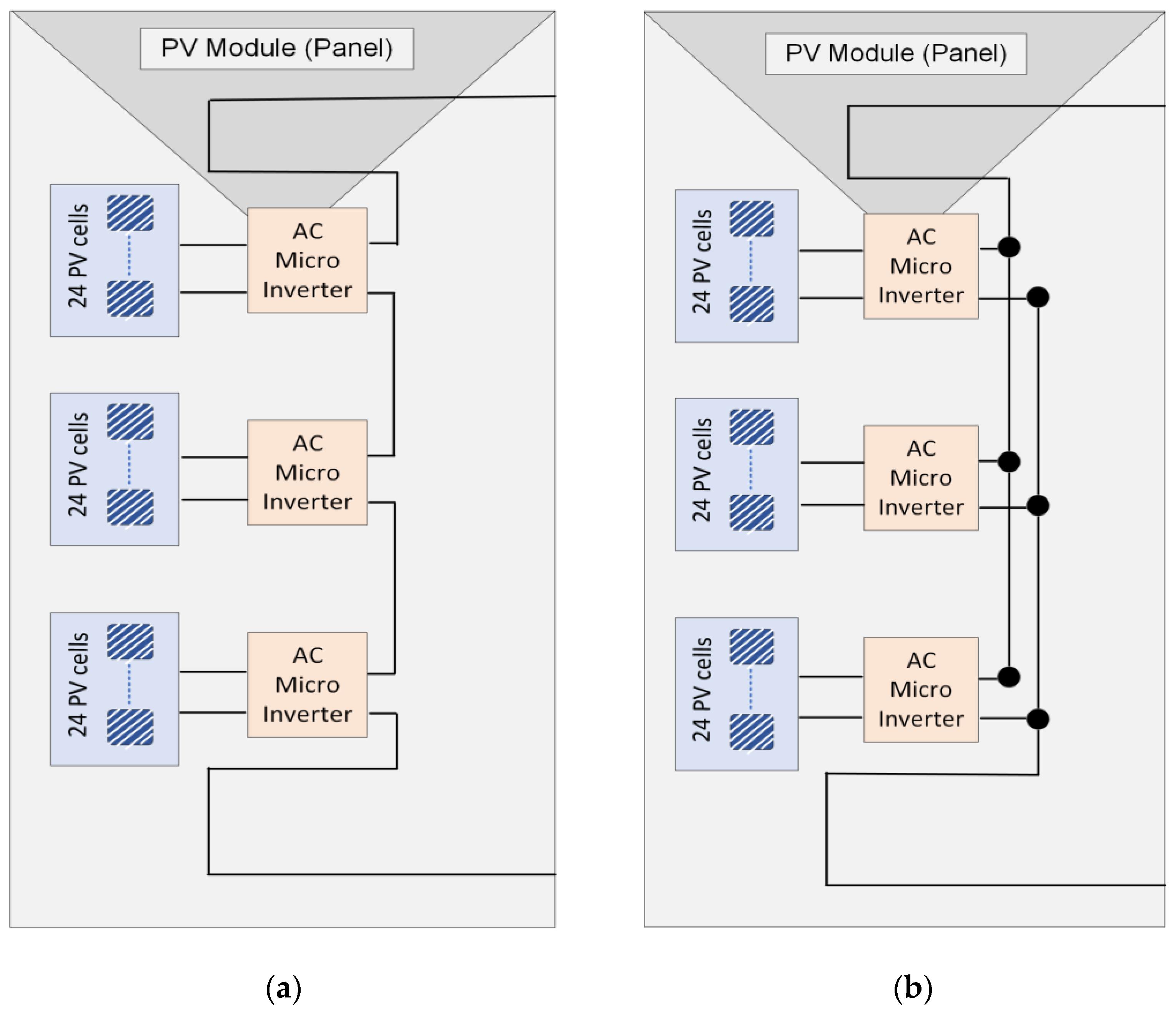
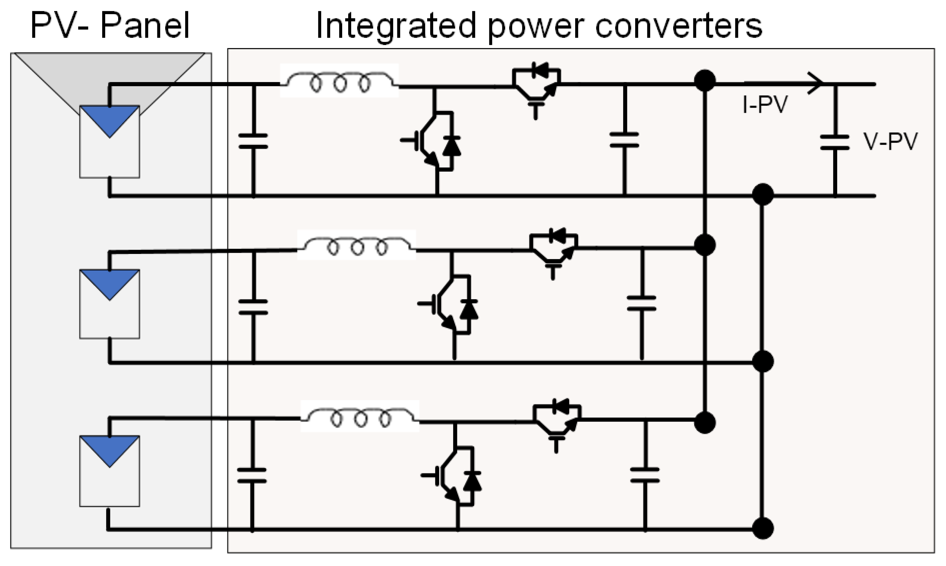
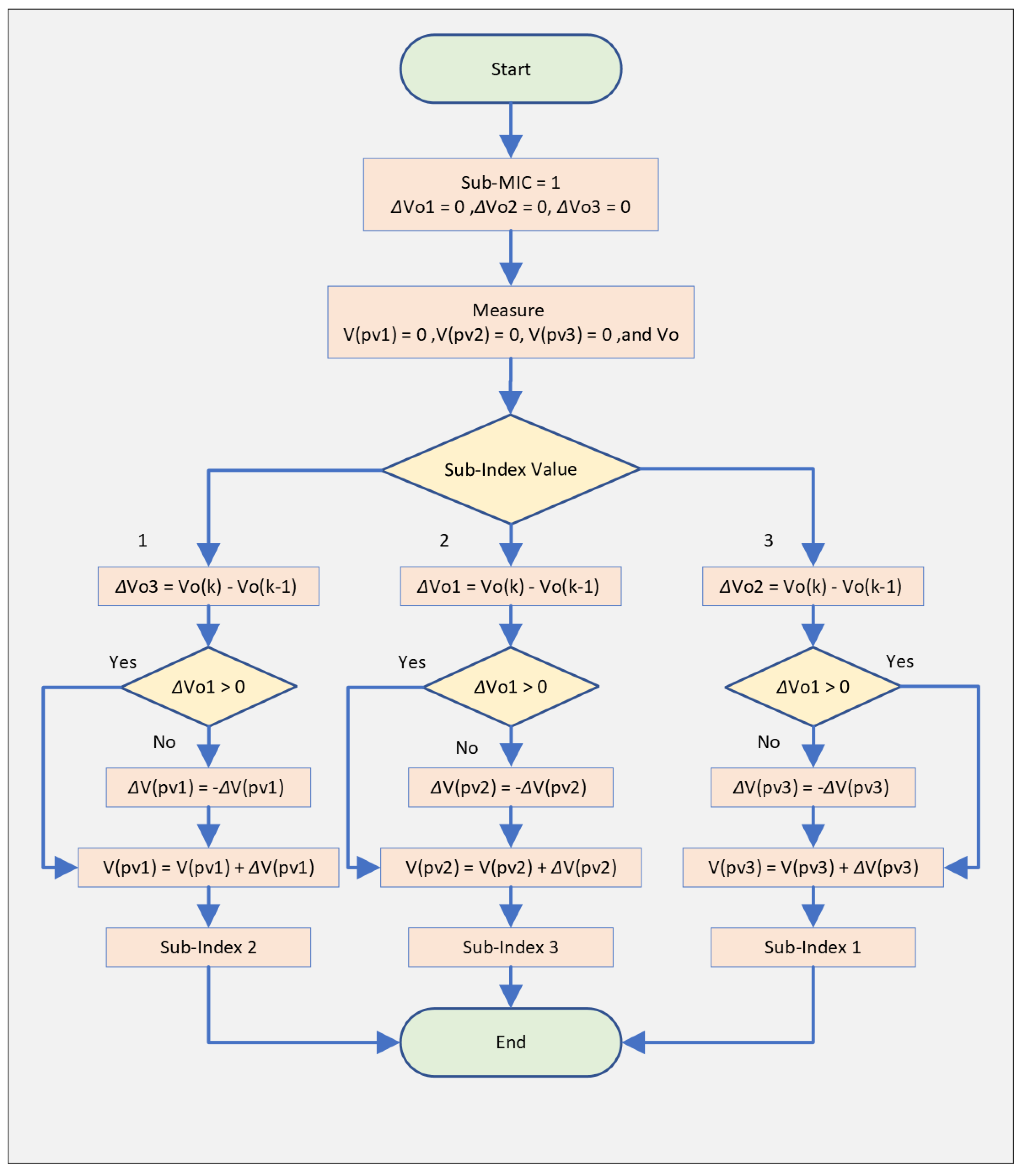
3.1. Sub-Module MI

The harvested energy from the residential PV system can be significantly increased by applying power conditioning to the sub-panel level [47]. Appling the DMPPT at the sub-panel level can mitigate the mismatch issue between sub-panels inside the same PV module, increasing energy harvesting of the overall PV system [83]. Cascaded DC–DC optimizers have been used to reduce the sub-panel mismatch problem and optimize the residential PV system efficiency [71,76]. However, the installation cost of this system might rise when compared with the other types and also more complex controllers will be required. Employing differential power processing (DPP) DC–DC converters is another strategy to apply power conditioning at the PV sub-panel level [77,84].
The main objective of DPP converters is to equalize the photocurrent of the PV sub-panel during the mismatch conditions. The complexity of the controlling process and the high installation cost are the main drawbacks of this optimization method. A sub-module microinverter (SMMI) can be a promising solution to effectively utilize the PV power from each sub-panel and improve the total PV system’s efficiency [85]. This futuristic strategy can convert the DC current of the PV sub-panel to an AC current and link the output current to the utility grid with no need for a central DC–AC inverter. Figure 8 illustrates both series and parallel grid-connected MIs at the sub-panel level, which will be presented in the next subsections.

3.2. Sub-Module Series Converters

The PV SM DC–DC optimizer proposed in [86] aims to increase energy capture of the PV module during the unbalanced power generation of PV submodules. This study employed a synchronous buck converter topology to mitigate the PV SM mismatch issue efficiently. Low-cost devices with small sizes are used in the design stage to increase the switching frequency range. The synchronous buck converters are cascaded to build higher output voltage and avoid further step-up power converter circuits. The controlling process of the SM DC–DC optimizer is relatively simple since no communication is required between the SM controller during a mismatch effect. Figure 9 shows a schematic drawing of the SM DC–DC optimizer.
In terms of MPPT control, each PV SM power is tracked using the perturb and observe (P&O) algorithm. The DC–DC optimizer strategy overcomes the several maximum points problem caused by the bypass diode under unbalanced power generation. The string current of the three SMs can be considered a constant value since they are connected in series. Thus, the controlling parameter used to track the maximum power point is the corresponding voltage of each PV SM. This becomes a direct optimization problem that aims to obtain the maximum power by varying the duty cycle of each DC–DC optimizer. The flow chart in Figure 10 illustrates the MPPT algorithm used to track the local MPP of each PV SM.
The local algorithm will start by initializing the parameters of the DC–DC converter. Then it will sample the voltage output. Comparing the output voltage with the recorded maximum voltage can determine the next step. If the duty-cycle ratio can achieve the maximum output voltage, the first algorithm will stop and the output duty ratio will become the input of the next tracking algorithm. Otherwise, the new duty ratio will be calculated by perturbing the first duty ratio. After the approximate MPP is found by the first algorithm, the P&O algorithm will be used to calculate the accurate MPP. The output duty-cycle ratio from the first algorithm is used as the inial value of the second algorithm. This duty ratio will be perturbed and voltage will be sampled accordingly. The direction of the next tracking cycle can be decided by comparing the voltage of the current cycle with the voltage of the previous tracking cycle.
Zhu et al. in [87] propose an SM single-inductor single-sensor DC–DC optimizer to reduce the converter SM MI’s size and cost. With only a single inductor and a single sensor, this optimizer can make three SMs work on independent MPPs to maximize the energy harvest. The suggested buck converters are connected in series to step up higher output voltage. The MPPT algorithm used in this topology is the perturb and observe algorithm. The major drawback of such a connection is that a single MPPT system is applied for the three SMs of the PV panel. Thus, energy harvesting and PV system performance might be negatively affected. Figure 11 shows the circuit configuration of the novel topology that is based on a single inductor and single current sensor.
To control the MPP of each SM, the adaptive perturb and observe (P&O) algorithm has been used to perturb the PV module current and decide the direction of the next cycle. The PV module current is sensed and compared to each SM’s current, which is used as the reference current of the next tracking period. The duty–cycle ratio used for operating the SM converters is calculated as the ratio between the SM current and the module current in one tracking cycle. Figure 12 shows the flow chart of the adaptive MPP algorithm used in this study, where the clock parameter is a factor that decides which SM should be tracked.
The algorithm will start by sampling the PV SM current iL.
The clock value is regularly increased and decided which SM should be tracked. When the value of the clock is between 0 and t, the controller will track the MPP of the first SM while the seconded SM MPP can be tracked if the clock value ranges from t and 2 t. The MPPT controller can track the third SM if the clock value is greater than 2 t and less than 3 t. The clock will reset after its value exceeds 3 t. Once the controller decides which SM should be tracked, the corresponding current of the tracked SM is divided by the PV module current, and the result becomes the duty ratio of the SM DC–DC converter.

3.3. Sub-Module Parallel Converters

The low voltage of solar cells makes the boost converter topologies more practical for several PV applications. The boost converters are commonly used in parallel connection to step up the low voltage level to the grid voltage level. One of the common SM parallel converters is a synchronous boost converter [88]. This topology aims to solve the SM mismatch problem and effectively increase PV energy yield. The proposed converter is based on connecting the SM-integrated converter in parallel. The MPP of each SM can be captured individually to maximize energy harvesting and mitigate power loss. The external connection between PV modules is in series to build up sufficient output voltage. Figure 13 illustrates the circuit configuration of the SM parallel integrated converter.
One MPPT microcontroller has been used to regulate the three SMs on the PV panel since the three converters are connected in parallel. The perturb and observe (P&O) tracking algorithm was used to track the MPP of each SM. The PV module output voltage is used as a reference value to compare with SM voltages and then decide the direction of the next tracking cycle. In every cycle of the tracking process, the three voltages of the SMs are perturbed and compared with the output voltage. Figure 14 shows the MPPT controlling algorithm flow chart used in [88].
The first step of the MPPT algorithm is initializing the parameters of the tracking system. Then the algorithm starts to measure the output voltage and PV SM voltage of three SM voltages. The SM indices decide which SM voltage is controlled. The three SM voltages will be perturbed continuously and the change of the output voltage of the PV module will be recorded. The PV module will have three indices, but they are not shown in Figure 14. The change in the output voltage of the PV module index will be measured according to changes in SM voltages. The direction of the tracking cycle of each SM can be decided according to the change of output voltage based on perturbing respective SM voltages. The tracking algorithm will continue in the same direction if a change in output voltage is positive, otherwise the direction of the tracking process will be reversed.

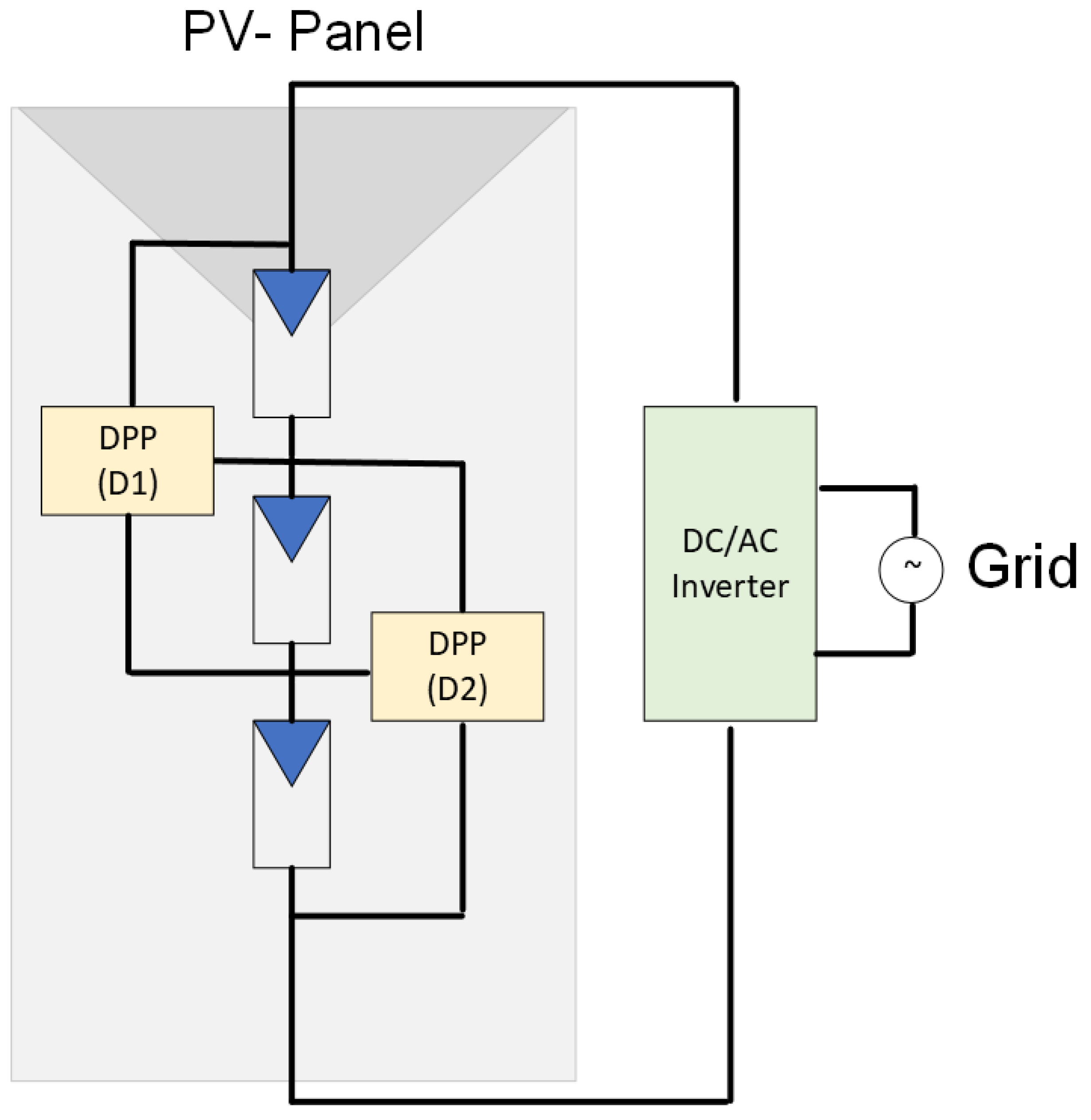
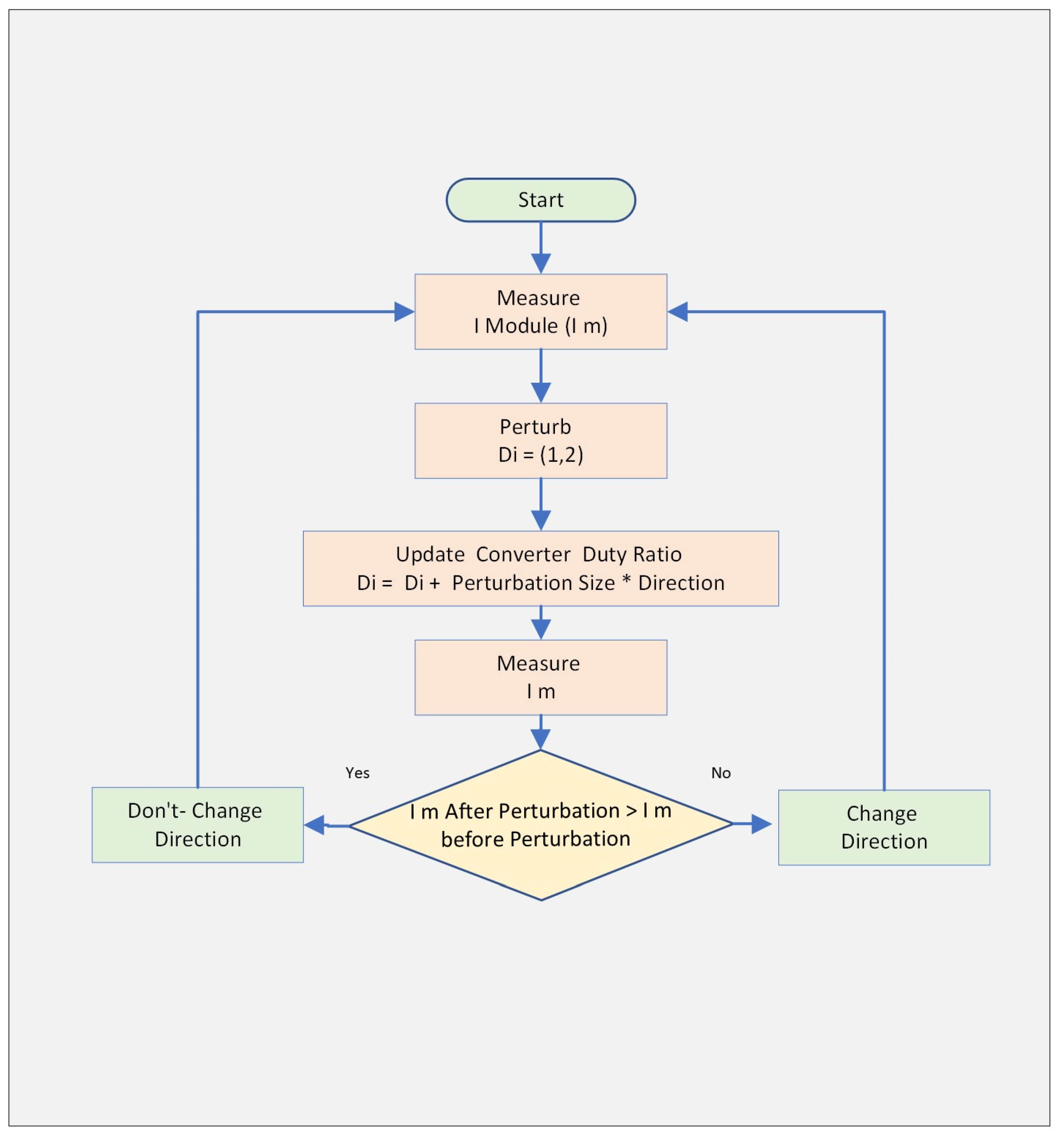
3.4. Sub-Module Differential Power Processing Converters

In [89], a differential power processing (DPP) topology for PV SM MPPT implementation has been proposed. This study employs DPP PV–PV topology with a bidirectional buck-boost converter to solve the mismatch issue between the PV SMs to maximize energy harvesting and reduce power losses. The main objective of the proposed design is to efficiently balance the current between the PV SMs under unequal power generation. Figure 15 illustrates the DPP PV–PV architecture that is used to mitigate mismatch issues between the PV SMs.
The P&O algorithm is employed to track the MPP. The DPP converter operates at a relatively high frequency, thus the PV module voltage is assumed to be constant. Since the PV module voltage is assumed to be static, the PV module current is used as an indicator to decide the direction of the next tracking cycle. The proposed topology in [89] employs two loops to track the MPP. The fast-controlling loop operates the DPP buck-boost converters while the slower loop controls the DC–AC grid-tied inverter. Figure 16 shows the flow chart of the fast-controlling loop of DPP buck-boost converters.
The tracking algorithm will start by measuring the PV module current before perturbing the duty–cycle ratio of the DC–DC converters. Then, the DPP converter duty ratio will be updated by adding a perturbing sample. The change of PV module current is sensed and recorded after regularly varying the duty ratio of DPP converters. The new value of the PV module current is compared with the previous value. When the PV module current before perturbation is greater than the PV module current after perturbation, the direction of the tracking process will change; otherwise, the tracking direction will not change.
Technical comparison results of some DMPPT topologies used in PV SMs are illustrated in Table 2. It summarizes power electronic devices that are used to obtain the maximum power of PV SMs and illustrates that the P&O tracking algorithm is employed to track the maximum power of PV SMs for most proposed converters. This is to reduce the overhead complexity of MPPT controllers. However, some research modified the conventional P&O algorithm to enable tracking the maximum power of each SM using a single MPPT system. It can be also noted that several researchers have proven a significant increase in power harvesting due to employing DMPPT at the PV SM level. From a power converter perspective, it can be seen that several research projects rely on conventional power electronic circuits including buck, boost, and flyback converters. Some others use DPP topologies to equalize the current of the PV module by redirecting the SM current flow according to the irradiation level.

4. Discussions and Recommendations

Distributing the MPPT control to obtain the maximum available power from each PV SM individually enables maximizing the overall power generation of the PV module, especially under the effect of the mismatch issue. The accuracy of the MPPT system is improved due to employing the DMPPT approach at the PV SM level, and hence the multiple MPPs problem caused by bypass diodes is significantly mitigated. The performance of the PV power electronic converter bocomes slightly different according to the converter’s characteristics and the material used in the manufacturing process. The MPPT controller techniques have been thoroughly reviewed in this study. This section presents a discussion of the power converters for applying the DMPPT strategy to increase the power generation of the PV module and improve the overall efficiency of the PV system.
The power electronic converters used in employing the DMPPT approach in PV SMs should be developed in the future to fulfill the technological requirements in the power circuit topologies, the MPPT techniques, semiconductor materials, the power quality requirements, and grid standards. New power electronic topologies should be developed with fewer components, better efficiency, and reduced cost to effectively apply the DMPPT approach at the PV SM level. These converters are expected to achieve the following recommendations:
  • The value of the input capacitors plays an important role in determining the lifetime of the power electronic converters. Thus, a new decoupling circuit is needed. The new power electronic devices’ efficiency should be improved due to applying soft switching techniques. Soft switching technologies not only improve the PV system’s efficiency but also can increase the lifetime of the power electronic converters.
  • The power electronic switch is a basic element in the design of the power converters and choosing switches with lower switching and conduction losses enables achieving better efficiencies. It has been proven that GaN- and SiC-based power electronic switches can achieve better efficiency and effectively minimize power losses. The on-state resistance between the drain and the source of such switches is relatively low, which minimizes the conduction losses of the switch. Also, high switching frequencies are achievable with minimal switching losses.
  • In terms of power quality, galvanic isolation is not mandatory nowadays; however, many researchers consider it in the design stage since it protects against electrical faults.
  • Anti-islanding detection is another feature that should be considered in the new designs; the detection strategies should be swift and accurate to cope with power grid failure.
  • The power quality is directly affected by THD and hence it should be minimized to improve the power electronic devices. The power quality discussion cannot be completed without emphasizing the importance of achieving and maintaining a unity power factor system.
  • The development of a novel MPPT controller is important to maintain the voltage level and help achieve the maximum available power from the PV side. The new MPPT controllers should be able to pump up the extra power and maintain MPPT in the daytime and enable compensation mode during nighttime.

5. Future Trends of the Grid-Tied MI

The partial and full shading effect on PV systems can be unpredictable and unavoidable in most scenarios. Partial shading might be a result of several issues, including trees and building shadows, clouds, and bird droppings. The electrical characteristics of the shaded part of the PV system become different from those of the unshaded part. The percentage of irradiation level on the PV SM is directly proportional to the amount of generated power. Thus, PV SMs with a high irradiation level can generate more power compared to PV SMs with a low irradiation level. The PV system will be limited by PV SMs with the lowest irradiation level causing a mismatch between PV SMs.
The PV SM mismatches have a negative impact on the performance of the PV system. The series connection of the SMs results in limiting of the PV module current by SMs with the lowest output current. Harvesting each SM’s maximum power individually not only significantly increases power capturing of the PV module but also mitigates the power losses. DMPPT at the SM level aims to obtain the true available power by summing the individual maximum power of the three SMs of a single PV module. New optimized power electronic topologies are expected to be invented to further improve PV system performance and achieve better efficiencies. These topologies are needed to overcome the currently associated limitations and provide reduced-size components. Large band-gap devices such as GaN and SiC might be a promising solution to enhance PV system efficiency and enable use of small components by allowing higher switching frequency.
One major issue that reduces the PV system power generation is the mismatch between PV SMs during unbalanced power generation. The mismatch phenomena might occur as a result of several reasons; however, partial shading can be the most common contributing factor to this concern. The behavior of the PV SM is different according to the environmental conditions of each SM. PV SMs are a part of the PV panel and they are internally connected. Thus, applying the DMPPT strategy at the SM level requires breaking the interconnection between SMs. Therefore, PV panel manufacturers might revise the current electrical arrangement inside the PV panel junction box and provide a new electrical layout considering the capability of integrating a new power converter to implement DMPPT at the PV SM level.
Working at the PV SM level and adding optimized power electronic converters can increase energy harvesting in different types of PV systems. The amount of harvested energy extracted from the PV system can significantly increase when more DMPPT is implemented among PV SMs, especially under the partial shading effect. Proposing new power electronic converters that offer better efficiency and improve the overall performance of the PV system should be the focus of associated future work. Employing these optimized power electronic converters in PV SMs can mitigate the mismatch concerns and maximize power harvesting.

6. Conclusions

This paper discussed the DMPPT strategies which are a practical solution to mitigate the mismatch problem in different types of PV system topologies. The DMPPT approaches have been evaluated and compared for PV string, PV module, and PV SM systems. As the DMPPT approach is applied at a finer level, a more accurate MPP can be achieved, and the mismatch loss issue can be effectively minimized. It has been concluded that the most practical level where the DMPPT approach can be applied is the PV SM level. Thus, the main focus of this paper was to evaluate and compare the different power electronic converters used for applying DMPPT at the SM level. Also, this study examined the MPPT algorithm used to track the maximum power for different PV SM topologies. It has been concluded also that most PV SM control designs use or modify the conventional P&O tracking algorithms to avoid further complexity in the PV system design stage.
This review paper presents a comprehensive comparison between different power electronic converters that are used to implement the DMPPT approach at the PV SM level. Although the P&O MPPT algorithm might be the most commonly used tracking algorithm due to its simple implementation, the lack of tracking accuracy is a major concern about this technique. Future research should focus on utilizing new MPPT approaches such as artificial intelligence (AI) and optimization algorithm approaches to improve the accuracy of MPPT methods.

Author Contributions

Conceptualization, A.D.; methodology, Y.A. and A.D.; software, Y.A. and A.D.; validation, Y.A. and A.D.; formal analysis, Y.A. and A.D.; investigation, Y.A. and A.D.; resources, X.M. and A.D.; data curation, Y.A. and A.D.; writing—original draft preparation, Y.A.; writing—review and editing, X.M. and A.D.; visualization, Y.A. and A.D.; supervision, A.D. and X.M.; project administration, A.D. and X.M.; funding acquisition, A.D. and X.M. All authors have read and agreed to the published version of the manuscript.

Funding

This research received no external funding.

Data Availability Statement

Not applicable.

Conflicts of Interest

The authors declare no conflict of interest.

References

  1. Zahedi, A. A review of drivers, benefits, and challenges in integrating renewable energy sources into electricity grid. Renew. Sustain. Energy Rev. 2011, 15, 4775–4779. [Google Scholar] [CrossRef]
  2. Iweh, C.D.; Gyamfi, S.; Tanyi, E.; Effah-Donyina, E. Distributed generation and renewable energy integration into the grid: Prerequisites, push factors, practical options, issues and merits. Energies 2021, 14, 5375. [Google Scholar] [CrossRef]
  3. Kandemir, E.; Cetin, N.S.; Borekci, S. A comprehensive overview of maximum power extraction methods for PV Systems. Renew. Sustain. Energy Rev. 2017, 78, 93–112. [Google Scholar] [CrossRef]
  4. Kjaer, S.B.; Pedersen, J.K.; Blaabjerg, F. A review of single-phase grid-connected inverters for photovoltaic modules. IEEE Trans. Ind. Appl. 2005, 41, 1292–1306. [Google Scholar] [CrossRef]
  5. IEEE Std 1547-2003; IEEE Standard for Interconnecting Distributed Resources with Electric Power Systems. IEEE: Piscataway, NJ, USA, 2003; pp. 1–28.
  6. IEEE Std 1547.1-2020; IEEE Standard Conformance Test Procedures for Equipment Interconnecting Distributed Energy Resources with Electric Power Systems and Associated Interfaces. IEEE: Piscataway, NJ, USA, 2020; pp. 1–282.
  7. IEEE P1547.1a/D5; IEEE Approved Draft Standard Conformance Test Procedures for Equipment Interconnecting Distributed Resources with Electric Power Systems Amendment 1. IEEE: Piscataway, NJ, USA, 2015; pp. 1–19.
  8. Badawy, A. Current Source DC-DC and DC-AC Converters with Continuous Energy Flow. Ph.D. Thesis, University of Strathclyde, Glasgow, UK, 2015. [Google Scholar]
  9. Infield, D.G.; Onions, P.; Simmons, A.D.; Smith, G.A. Power quality from multiple grid-connected single-phase inverters. IEEE Trans. Power Deliv. 2004, 19, 1983–1989. [Google Scholar] [CrossRef]
  10. Abdelsalam, A.K.; Massoud, A.; Darwish, A.; Ahmed, S. Simplified Generic On-Line PWM Technique for Single Phase Grid Connected Current Source Inverters. In Proceedings of the 2012 Twenty-Seventh Annual IEEE Applied Power Electronics Conference and Exposition (APEC), Orlando, FL, USA, 5–9 February 2012. [Google Scholar]
  11. Darwish, A.; Ahmed, S. A Single-Stage Three-Phase DC/AC Inverter Based on Cuk Converter for PV Application. In Proceedings of the 2013 7th IEEE GCC Conference and Exhibition (GCC), Doha, Qatar, 17–20 November 2013; pp. 384–389. [Google Scholar] [CrossRef] [Green Version]
  12. Darwish, A.; Massoud, A.M.; Ahmed, S. Single Phase Grid Connected Current Source Inverter: Mitigation of Oscillating Power Effect on The Grid Current. In Proceedings of the IET Conference on Renewable Power Generation (RPG 2011), Edinburgh, UK, 6–8 September 2011. [Google Scholar]
  13. Darwish, A.; Holliday, D.; Finney, S. Operation and Control Design of an Input-Conversion Scheme for Offshore DC Wind Systems. IET Power Electron. 2017, 10, 2092–2103. [Google Scholar] [CrossRef] [Green Version]
  14. Kabalcı, E. Review on novel single-phase grid-connected solar inverters: Circuits and control methods. Sol. Energy 2020, 198, 247–274. [Google Scholar] [CrossRef]
  15. Lee, J.; Chang, B.; Aktas, C.; Gorthala, R. Economic feasibility of campus-wide photovoltaic systems in New England. Renew. Energy 2016, 99, 452–464. [Google Scholar] [CrossRef] [Green Version]
  16. Haegermark, M.; Kovacs, P.; Dalenbäck, J.-O. Economic feasibility of solar photovoltaic rooftop systems in a complex setting: A Swedish case study. Energy 2017, 127, 18–29. [Google Scholar] [CrossRef]
  17. Duman, A.C.; Güler, Ö. Economic Analysis of grid-connected residential rooftop PV systems in Turkey. Renew. Energy 2020, 148, 697–711. [Google Scholar] [CrossRef]
  18. Rodrigues, S.; Torabikalaki, R.; Faria, F.; Cafôfo, N.; Chen, X.; Ivaki, A.R.; Mata-Lima, H.; Morgado-Dias, F. Economic feasibility analysis of small scale PV systems in different countries. Sol. Energy 2016, 131, 81–95. [Google Scholar] [CrossRef]
  19. Li, C.; Zhou, D.; Zheng, Y. Techno-economic comparative study of grid-connected PV power systems in five climate zones, China. Energy 2018, 165, 1352–1369. [Google Scholar] [CrossRef]
  20. Sagani, A.; Mihelis, J.; Dedoussis, V. Techno-Economic Analysis and life-cycle environmental impacts of small-scale building-integrated PV systems in Greece. Energy Build. 2017, 139, 277–290. [Google Scholar] [CrossRef]
  21. Chen, Z.; Blaabjerg, F.; Pedersen, J.K. A multi-functional power electronic converter in Distributed Generation Power Systems. In Proceedings of the IEEE 36th Conference on Power Electronics Specialists, Recife, Brazil, 12–16 June 2005. [Google Scholar]
  22. Ramakumar, R.; Bigger, J.E. Photovoltaic systems. Proc. IEEE 1993, 81, 365–377. [Google Scholar] [CrossRef]
  23. Xiao, W.; El Moursi, M.S.; Khan, O.; Infield, D. Review of grid-tied converter topologies used in photovoltaic systems. IET Renew. Power Gener. 2016, 10, 1543–1551. [Google Scholar] [CrossRef] [Green Version]
  24. Sridhar, V.; Umashankar, S. A comprehensive review on CHB MLI based PV inverter and feasibility study of CHB MLI based PV-Statcom. Renew. Sustain. Energy Rev. 2017, 78, 138–156. [Google Scholar] [CrossRef]
  25. Mohapatra, A.; Nayak, B.; Das, P.; Mohanty, K.B. A review on MPPT techniques of PV system under partial shading condition. Renew. Sustain. Energy Rev. 2017, 80, 854–867. [Google Scholar] [CrossRef]
  26. Belhachat, F.; Larbes, C. A review of Global Maximum Power Point tracking techniques of photovoltaic system under partial shading conditions. Renew. Sustain. Energy Rev. 2018, 92, 513–553. [Google Scholar] [CrossRef]
  27. Ahmed, J.; Salam, Z. A critical evaluation on maximum power point tracking methods for partial shading in PV systems. Renew. Sustain. Energy Rev. 2015, 47, 933–953. [Google Scholar] [CrossRef]
  28. Liu, Y.-H.; Chen, J.-H.; Huang, J.-W. A review of maximum power point tracking techniques for use in partially shaded conditions. Renew. Sustain. Energy Rev. 2015, 41, 436–453. [Google Scholar] [CrossRef]
  29. Femia, N.; Petrone, G.; Spagnuolo, G.; Vitelli, M. Optimization of perturb and observe maximum power point tracking method. IEEE Trans. Power Electron. 2005, 20, 963–973. [Google Scholar] [CrossRef]
  30. Safari, A.; Mekhilef, S. Simulation and hardware implementation of incremental conductance MPPT with direct control method using CUK converter. IEEE Trans. Ind. Electron. 2011, 58, 1154–1161. [Google Scholar] [CrossRef]
  31. Noguchi, T.; Togashi, S.; Nakamoto, R. Short-current pulse-based maximum-power-point tracking method for multiple photovoltaic-and-converter module system. IEEE Trans. Ind. Electron. 2002, 49, 217–223. [Google Scholar] [CrossRef]
  32. Díez-Mediavilla, M.; Dieste-Velasco, M.I.; Rodríguez-Amigo, M.C.; García-Calderón, T.; Alonso-Tristán, C. Performance of grid-tied PV facilities based on real data in Spain: Central Inverter Versus String System. Energy Convers. Manag. 2014, 86, 1128–1133. [Google Scholar] [CrossRef] [Green Version]
  33. Zeng, Z.; Yang, H.; Zhao, R.; Cheng, C. Topologies and control strategies of multi-functional grid-connected inverters for Power Quality Enhancement: A comprehensive review. Renew. Sustain. Energy Rev. 2013, 24, 223–270. [Google Scholar] [CrossRef]
  34. Bae, Y.; Vu, T.-K.; Kim, R.-Y. Implemental Control Strategy for grid stabilization of grid-connected PV system based on German grid code in symmetrical low-to-medium voltage network. IEEE Trans. Energy Convers. 2013, 28, 619–631. [Google Scholar] [CrossRef]
  35. Romero-Cadaval, E.; Spagnuolo, G.; Franquelo, L.G.; Ramos-Paja, C.A.; Suntio, T.; Xiao, W.M. Grid-connected photovoltaic generation plants: Components and Operation. IEEE Ind. Electron. Mag. 2013, 7, 6–20. [Google Scholar] [CrossRef] [Green Version]
  36. Altin, N.; Ozdemir, S. Three-phase three-level grid interactive inverter with fuzzy logic based maximum power point tracking controller. Energy Convers. Manag. 2013, 69, 17–26. [Google Scholar] [CrossRef]
  37. Ozdemir, S.; Altin, N.; Sefa, I. Single Stage Three Level Grid Interactive MPPT inverter for PV Systems. Energy Convers. Manag. 2014, 80, 561–572. [Google Scholar] [CrossRef]
  38. Altin, N.; Sefa, İ. DSPACE based adaptive neuro-fuzzy controller of grid interactive inverter. Energy Convers. Manag. 2012, 56, 130–139. [Google Scholar] [CrossRef]
  39. Darwish, A.; Holliday, D.; Ahmed, S.; Massoud, A.M.; Williams, B.W. A Single-Stage Three-Phase Inverter Based on Cuk Converters for PV Applications. IEEE J. Emerg. Sel. Top. Power Electron. 2014, 2, 797–807. [Google Scholar] [CrossRef]
  40. Picault, D.; Raison, B.; Bacha, S. Guidelines for evaluating Grid Connected PV system topologies. In Proceedings of the 2009 IEEE International Conference on Industrial Technology, Churchill, VIC, Australia, 10–13 February 2009. [Google Scholar]
  41. Balato, M.; Vitelli, M. Optimization of distributed maximum power point tracking PV applications: The scan of the power vs. voltage input characteristic of the inverter. Int. J. Electr. Power Energy Syst. 2014, 60, 334–346. [Google Scholar] [CrossRef]
  42. Zhao, T.; Ju, Z.; Wang, H.; Wei, X.; Li, X.; Zhang, S. The Distributed Maximum Power Point Tracking Method and application in the PV grid-connected generation. In Proceedings of the 2010 International Conference on Intelligent System Design and Engineering Application, Changsha, China, 13–14 October 2010. [Google Scholar]
  43. Wang, F.; Zhu, T.; Zhuo, F.; Yang, Y. Analysis and comparison of FPP and DPP structure based DMPPT PV system. In Proceedings of the 2016 IEEE 8th International Power Electronics and Motion Control Conference (IPEMC-ECCE Asia), Hefei, China, 22–26 May 2016. [Google Scholar]
  44. Vitelli, M. On the necessity of joint adoption of both Distributed Maximum Power Point Tracking and central maximum power point tracking in PV Systems. Prog. Photovolt. Res. Appl. 2012, 22, 283–299. [Google Scholar]
  45. Femia, N.; Lisi, G.; Petrone, G.; Spagnuolo, G.; Vitelli, M. Distributed maximum power point tracking of photovoltaic arrays: Novel approach and system analysis. IEEE Trans. Ind. Electron. 2008, 55, 2610–2621. [Google Scholar] [CrossRef] [Green Version]
  46. Salam, Z.; Ramli, M.Z. Distributed maximum power point tracker for additional energy harvesting during partial shading of PV System. In Proceedings of the 2015 First Workshop on Smart Grid and Renewable Energy (SGRE), Doha, Qatar, 22–23 March 2015. [Google Scholar]
  47. Shmilovitz, D.; Levron, Y. Distributed maximum power point tracking in photovoltaic systems—Emerging architectures and control methods. Automatika 2012, 53, 142–155. [Google Scholar] [CrossRef]
  48. Bosman, L.B.; Leon-Salas, W.D.; Hutzel, W.; Soto, E.A. PV system predictive maintenance: Challenges, current approaches, and opportunities. Energies 2020, 13, 1398. [Google Scholar] [CrossRef] [Green Version]
  49. Barchowsky, A.; Parvin, J.P.; Reed, G.F.; Korytowski, M.J.; Grainger, B.M. A comparative study of MPPT methods for distributed photovoltaic generation. In Proceedings of the 2012 IEEE PES Innovative Smart Grid Technologies (ISGT), Washington, DC, USA, 16–20 January 2012. [Google Scholar]
  50. Lameirinhas, R.A.M.; Torres, J.P.; de Melo Cunha, J.P. A Photovoltaic Technology Review: History, fundamentals and applications. Energies 2022, 15, 1823. [Google Scholar] [CrossRef]
  51. Lyden, S.; Haque, M.E. Maximum power point tracking techniques for photovoltaic systems: A Comprehensive Review and Comparative Analysis. Renew. Sustain. Energy Rev. 2015, 52, 1504–1518. [Google Scholar] [CrossRef]
  52. IEEE Std 1547.2-2008; IEEE Application Guide for IEEE Std 1547(TM), IEEE Standard for Interconnecting Distributed Resources with Electric Power Systems. IEEE: Piscataway, NJ, USA, 2009; pp. 1–217.
  53. Darwish, A.; Alotaibi, S.; Elgenedy, M.A. Current-Source Single-Phase Module Integrated Inverters for PV Grid-Connected Applications. IEEE Access 2020, 8, 53082–53096. [Google Scholar] [CrossRef]
  54. Darwish, A.; Elgenedy, M.A. Current-Source Modular Medium-Voltage Grid-Connected System with High-Frequency Isolation for Photovoltaic Applications. IEEE Trans. Energy Convers. 2019, 34, 255–266. [Google Scholar] [CrossRef] [Green Version]
  55. Darwish, A.; Massoud, A.; Holliday, D.; Ahmed, S.; Williams, B. Generation, performance evaluation and control design of single-phase differential-mode buck–boost current-source inverters. IET Renew. Power Gener. 2016, 10, 916–927. [Google Scholar] [CrossRef] [Green Version]
  56. Wiechmann, E.P.; Aqueveque, P.; Burgos, R.; Rodriguez, J. On the Efficiency of Voltage Source and Current Source Inverters for High-Power Drives. IEEE Trans. Ind. Electron. 2008, 55, 1771–1782. [Google Scholar] [CrossRef]
  57. Zhou, Y.; Liu, Y.; Su, M.; Sun, Y. A Single-phase Voltage Source Inverter with Lower-Voltage-Rated Capacitor and Ripple Power Decoupling Function. In Proceedings of the 2020 15th IEEE Conference on Industrial Electronics and Applications (ICIEA), Kristiansand, Norway, 9–13 November 2020. [Google Scholar]
  58. Eshkaftaki, R.A.; Ho, C.N.M. Half-Bridge Current Source Inverter for Grid-Connected Applications. In Proceedings of the 2022 IEEE Energy Conversion Congress and Exposition (ECCE), Detroit, MI, USA, 9–13 October 2022. [Google Scholar]
  59. Blaabjerg, F.; Chen, Z.; Kjaer, S.B. Power Electronics as efficient interface in Dispersed Power Generation Systems. IEEE Trans. Power Electron. 2004, 19, 1184–1194. [Google Scholar] [CrossRef]
  60. Hassaine, L.; OLias, E.; Quintero, J.; Salas, V. Overview of power inverter topologies and control structures for grid connected photovoltaic systems. Renew. Sustain. Energy Rev. 2014, 30, 796–807. [Google Scholar] [CrossRef]
  61. Ankit; Sahoo, S.K.; Sukchai, S.; Yanine, F.F. Review and Comparative Study of single-stage inverters for a PV system. Renew. Sustain. Energy Rev. 2018, 91, 962–986. [Google Scholar] [CrossRef]
  62. Wu, T.-F.; Chang, C.-H.; Lin, L.-C.; Kuo, C.-L. Power loss comparison of single- and two-stage grid-connected photovoltaic systems. IEEE Trans. Energy Convers. 2011, 26, 707–715. [Google Scholar] [CrossRef]
  63. Nguyen, D.; Lehman, B. An adaptive solar photovoltaic array using model-based reconfiguration algorithm. IEEE Trans. Ind. Electron. 2008, 55, 2644–2654. [Google Scholar] [CrossRef]
  64. Chen, L.; Amirahmadi, A.; Zhang, Q.; Kutkut, N.; Batarseh, I. Design and implementation of three-phase two-stage grid-connected module integrated converter. IEEE Trans. Power Electron. 2014, 29, 3881–3892. [Google Scholar] [CrossRef]
  65. Kjaer, S.B.; Pedersen, J.K.; Blaabjerg, F. Power inverter topologies for photovoltaic modules-A Review. In Proceedings of the Conference Record of the 2002 IEEE Industry Applications Conference. 37th IAS Annual Meeting (Cat. No.02CH37344), Pittsburgh, PA, USA, 13–18 October 2002. [Google Scholar]
  66. Boemer, J.C.; Burges, K.; Zolotarev, P.; Lehner, J.; Wajant, P.; Fürst, M.; Brohm, R.; Kumm, T. Overview of German Grid Issues and Retrofit of Photovoltaic Power Plants in Germany for the Prevention of Frequency Stability Problems in Abnormal System Conditions of the ENTSO-E Region Continental Europe. In Proceedings of the 1st International Workshop on Integration of Solar Power into Power Systems, Aarhus, Denmark, 24 October 2011. [Google Scholar]
  67. Ayswarya, S.; Prabhu, P. Leakage current suppression for transformerless inverter for Grid Connected PV Power Systems. In Proceedings of the 2014 International Conference on Electronics, Communication and Computational Engineering (ICECCE), Hosur, India, 17–18 November 2014. [Google Scholar]
  68. Bae, Y.; Kim, R.-Y. Suppression of common-mode voltage using a Multicentral photovoltaic inverter topology with synchronized PWM. IEEE Trans. Ind. Electron. 2014, 61, 4722–4733. [Google Scholar] [CrossRef]
  69. Martins, D.C. Analysis of a three-phase grid-connected PV power system using a modified dual-stage inverter. ISRN Renew. Energy 2013, 2013, 1–18. [Google Scholar] [CrossRef] [Green Version]
  70. Tran, T.Q.; Truong, A.V. MPPT voltage regulating in three-phase grid-connected photovoltaic system. Sci. Technol. Dev. J. 2012, 15, 50–61. [Google Scholar] [CrossRef]
  71. Renaudineau, H.; Donatantonio, F.; Fontchastagner, J.; Petrone, G.; Spagnuolo, G.; Martin, J.P.; Pierfederici, S. A PSO-Based Global MPPT Technique for Distributed PV Power Generation. IEEE Trans. Ind. Electron. 2015, 62, 1047–1058. [Google Scholar] [CrossRef]
  72. Badawy, M.O.; Bose, S.M.; Sozer, Y. A Novel Differential Power Processing Architecture for a Partially Shaded PV String Using Distributed Control. IEEE Trans. Ind. Appl. 2021, 57, 1725–1735. [Google Scholar]
  73. Pierquet, B.J.; Perreault, D.J. A Single-Phase Photovoltaic Inverter Topology with a Series-Connected Energy Buffer. IEEE Trans. Power Electron. 2013, 28, 4603–4611. [Google Scholar] [CrossRef] [Green Version]
  74. Zhang, X.; Chen, M.; Fu, Y.; Li, Y. A step-down partial power optimizer structure for photovoltaic series-connected power optimizer system. In Proceedings of the 2018 IEEE International Power Electronics and Application Conference and Exposition (PEAC), Shenzhen, China, 4–7 November 2018. [Google Scholar]
  75. Rabiul Islam, M.; Mahfuz-Ur-Rahman, A.M.; Muttaqi, K.M.; Sutanto, D. State-of-The-Art of the Medium-Voltage Power Converter Technologies for Grid Integration of Solar Photovoltaic Power Plants. IEEE Trans. Energy Convers. 2019, 34, 372–384. [Google Scholar] [CrossRef]
  76. Walker, G.R.; Sernia, P.C. Cascaded DC-DC converter connection of photovoltaic modules. IEEE Trans. Power Electron. 2004, 19, 1130–1139. [Google Scholar] [CrossRef]
  77. Qin, S.; Morrison, A.J.; Pilawa-Podgurski, R.C. Enhancing micro-inverter energy capture with sub-module differential power processing. In Proceedings of the 2014 IEEE Applied Power Electronics Conference and Exposition—APEC 2014, Fort Worth, TX, USA, 16–20 March 2014. [Google Scholar]
  78. Kwon, J.-M.; Kwon, B.-H.; Nam, K.-H. Three-Phase Photovoltaic System with Three-Level Boosting MPPT Control. IEEE Trans. Power Electron. 2008, 23, 2319–2327. [Google Scholar] [CrossRef] [Green Version]
  79. Keyhani, H.; Toliyat, H.A. Single-Stage Multistring PV Inverter with an Isolated High-Frequency Link and Soft-Switching Operation. IEEE Trans. Power Electron. 2014, 29, 3919–3929. [Google Scholar] [CrossRef]
  80. Rojas, C.A.; Aguirre, M.; Kouro, S.; Geyer, T.; Gutierrez, E. Leakage Current Mitigation in Photovoltaic String Inverter Using Predictive Control with Fixed Average Switching Frequency. IEEE Trans. Ind. Electron. 2017, 64, 9344–9354. [Google Scholar] [CrossRef]
  81. Alharbi, Y.; Darwish, A. Control of Cuk-Based Microinverter Topology with Energy Storage for Residential PV Applications. Energies 2023, 16, 2293. [Google Scholar] [CrossRef]
  82. Surirey, Q.; Hernandez-Vidal, R.; Renaudineau, H.; Kouro, S.; Cabon, B. Sub-module photovoltaic microinverter with cascaded push-pull and unfolding H-bridge inverter. In Proceedings of the 2017 IEEE Southern Power Electronics Conference (SPEC), Puerto Varas, Chile, 4–7 December 2017. [Google Scholar]
  83. Leuenberger, D.; Biela, J. PV-module-integrated AC inverters (AC modules) with subpanel MPP tracking. IEEE Trans. Power Electron. 2017, 32, 6105–6118. [Google Scholar]
  84. Bell, R.; Pilawa-Podgurski, R.C. Decoupled and distributed maximum power point tracking of series-connected photovoltaic submodules using differential power processing. IEEE J. Emerg. Sel. Top. Power Electron. 2015, 3, 881–891. [Google Scholar]
  85. Strache, S.; Wunderlich, R.; Heinen, S. A comprehensive, quantitative comparison of inverter architectures for various PV systems, PV cells, and irradiance profiles. IEEE Trans. Sustain. Energy 2014, 5, 813–822. [Google Scholar]
  86. Pilawa-Podgurski, R.C.; Perreault, D.J. Submodule Integrated Distributed Maximum Power Point Tracking for solar photovoltaic applications. IEEE Trans. Power Electron. 2013, 28, 2957–2967. [Google Scholar]
  87. Zhu, T.; He, X.; Guan, T.; Wang, F.; Yi, H.; Zhuo, F. An integrated single inductor-single sensor based photovoltaic optimizer with an optimal current point tracking strategy. In Proceedings of the 2017 IEEE Energy Conversion Congress and Exposition (ECCE), Cincinnati, OH, USA, 1–5 October 2017. [Google Scholar]
  88. Khan, O.; Xiao, W.; Moursi, M.S. A new PV system configuration based on submodule integrated converters. IEEE Trans. Power Electron. 2017, 32, 3278–3284. [Google Scholar]
  89. Qin, S.; Barth, C.B.; Pilawa-Podgurski, R.C. Enhancing microinverter energy capture with submodule differential power processing. IEEE Trans. Power Electron. 2016, 31, 3575–3585. [Google Scholar]
  90. Olalla, C.; Clement, D.; Rodriguez, M.; Maksimovic, D. Architectures and Control of Submodule Integrated DC–DC Converters for Photovoltaic Applications. IEEE Trans. Power Electron. 2013, 28, 2980–2997. [Google Scholar]
  91. Wang, F.; Zhu, T.; Zhuo, F.; Yi, H. An Improved Submodule Differential Power Processing-Based PV System with Flexible Multi-MPPT Control. IEEE J. Emerg. Sel. Top. Power Electron. 2018, 6, 94–102. [Google Scholar]
  92. Flores-Bahamonde, F.; Rojas, J.; Kouro, S.; Llor, A.M.; Rojas, C.A.; Perez, M.A. Sub-modular Power Optimizers Based on Partial Power Converters for Utility Scale PV Plants. In Proceedings of the IECON 2019—45th Annual Conference of the IEEE Industrial Electronics Society, Lisbon, Portugal, 14–17 October 2019. [Google Scholar]
  93. Lin, L.; Zhang, J.; Shao, S. Differential power processing architecture with virtual port connected in series and MPPT in submodule level. IEEE Access 2020, 8, 137897–137909. [Google Scholar]
Figure 1. Experimental results for inverters with a (a) high-order harmonic current and (b) low-order harmonic current (10 ms/div–5 A/div).
Energies 16 05468 g001
Figure 2. Experimental results for inverters during faults with a (a) slow dynamic response and (b) fast dynamic response (10 ms/div–5 A/div).
Energies 16 05468 g002
Figure 3. Generic configurations for DC/AC inverters: (a) VSI; (b) CSI.
Energies 16 05468 g003
Figure 4. The grid-connected PV system classification according to DMPPT level: (a) single central PV inverter; (b) multi-central PV inverter; (c) string PV inverter; (d) PV module MI.
Energies 16 05468 g004
Figure 5. Three-phase VSI as an example of central inverters.
Energies 16 05468 g005
Figure 6. Generic current–voltage and power–voltage curves for a PV module.
Energies 16 05468 g006
Figure 7. A standard 72-PV-cell panel circuit diagram: (a) the structure of the series connection of a 72-solar-cell PV panel and (b) the integrated junction box of the 72-cell PV panel.
Energies 16 05468 g007
Figure 8. Sub-module grid-connected micro inverter: (a) Series-connected MI and (b) Parallel-connected MI.
Energies 16 05468 g008
Figure 9. Diagram of the PV SM-integrated MPPT system.
Energies 16 05468 g009
Figure 10. A flowchart diagram showing the MPPT algorithms: (a) the global maximum point algorithm and (b) the typical P&O MPPT algorithm.
Energies 16 05468 g010
Figure 11. Configuration of the optimized buck-based MPPT system.
Energies 16 05468 g011
Figure 12. A flow chart illustrating the MPP algorithm according to the current of the PV SMs.
Energies 16 05468 g012
Figure 13. The connection between the PV sub-module and sub-panel micro converters of a single PV panel.
Energies 16 05468 g013
Figure 14. The flowchart shows the unified MPPT algorithm for capturing the MPP of PV sub-modules.
Energies 16 05468 g014
Figure 15. A schematic diagram of an MI with DPP.
Energies 16 05468 g015
Figure 16. A flowchart illustrating the algorithm for operating the DPP and balancing the current between PV SMs.
Energies 16 05468 g016
Table 1. Comparison of various grid-connected inverter topologies.
Ref. DMPPT LevelSingle/Three
Phase
Voltage Range (V)Rated PowerPV Interfaced ConverterGrid Interfaced Inverter
[78]Array Three38020 kWBoost Three-Phase VIS
[79]Multi-StringThree1801 kWHFAC LinkThree-Phase VIS
[80]StringSingle1101 kWH-NPCH-Bridge
[81]ModuleSingle2301 kWCukH-Bridge
[82]Sub-ModuleSingle220217 WPush–PullH-Bridge
Table 2. Comparison between different power electronic optimization studies to solve mismatch issues inside an individual PV panel.
Ref. Rated Power (W)TopologyArrangement MPPT
Algorithm
Efficiency (%)ImprovementsLimitations
[86]200 WSynchronous buckSeries P&O≈98 Increase power harvesting by (20%)Local maximum point controller
[87]-Buck SeriesP&O-Less
component
Single MPPT for three SMs
[88]100 WSynchronous boostParallel P&O≈96Improve efficiency due to using GaN technology Operating regardless of mismatch condition
[89]60 WSynchronous buck-boostDPPP&O=95The capability of commercial inverter integration Communication between neighboring DPPs
[90]60 WBidirectional flybackParallel-≈98 Reduce mismatch level by (25%)A large number of current sensors
[84]245 WDPP architecture with synchronous flyback convertersParallelDMPPT algorithm-Improve power extraction by 10.19%Large storage element required for decoupling purposes
[91]-DPP with central boostDPPP&O-Accurate MPP tracking Complex controlling process
[92]-Full bridge converter FBCSeriesP&O-Novel topology to apply DMPPT at a finer levelNo experimental validation
[93]300 WSynchronous boost with series virtual port DPPDPPModified P&O-A single current sensor is requiredMore components
Disclaimer/Publisher’s Note: The statements, opinions and data contained in all publications are solely those of the individual author(s) and contributor(s) and not of MDPI and/or the editor(s). MDPI and/or the editor(s) disclaim responsibility for any injury to people or property resulting from any ideas, methods, instructions or products referred to in the content.

