Article

Design of a Direct-Liquid-Cooled Motor and Operation Strategy for the Cooling System

1
Cluster of Excellence SE2A—Sustainable and Energy-Efficient Aviation, Technische Universität Braunschweig, 38106 Brauschweig, Germany
2
Institute for Drive Systems and Power Electronics, Leibniz Universität Hannover, 30823 Garbsen, Germany
3
Institute for Thermodynamics, Leibniz Universität Hannover, 30823 Garbsen, Germany
*
Author to whom correspondence should be addressed.
Energies 2023, 16(14), 5319; https://doi.org/10.3390/en16145319
Submission received: 12 June 2023 / Revised: 29 June 2023 / Accepted: 3 July 2023 / Published: 12 July 2023
(This article belongs to the Special Issue Regulations and Advances in High Performance Electric Motor and Drive)

Abstract

:
To make an all-electric aircraft possible, both high power densities and efficiencies are needed. However, particularly high demands are also placed on the thermal management system. Often, the electric motor and cooling system are considered without co-optimization. Particularly in the case of electric motors with conductors directly cooled by a liquid, there is great potential for optimization, since the temperature-dependent Joule losses determine the largest part of the losses. This publication shows the main influencing parameters for the electric motor and cooling system: coolant speed and winding temperature. In addition, the influence of the cooling system control during a flight mission is demonstrated and its potential in mass reduction is quantified. It could be shown that with a low utilized electric motor the maximum winding temperature of 130 ° C is beneficial, the cooling system should work in almost all operation points in its sized operation and the mass of the heat exchanger and pump is negligible compared to the mass of the electric motor and energy storage.

1. Introduction

For an all-electric aircraft, high demands are placed on the electric motor in terms of power density and efficiency. One approach to achieve this goal is a high-torque design. To achieve a high torque density, high current densities are required. High current densities set high requirements for the cooling of the winding system. A suitable approach for intense cooling of the winding system is direct liquid cooling (DLC) of the conductor. Direct liquid cooling requires cooling channels that are directly formed into the electric conductors. These cooling channels reduce the conductor area and thus lead to an increase in current density and consequently to higher losses at constant current, or in a second scenario to a reduction in current and thus in torque. The cooling system of the electric motor in the aircraft includes cooling channels in the winding as well as a coolant pump and a heat exchanger. On the one hand, these components contribute additional mass, in particular due to the additional energy storage for the cooling power, but on the other hand, the cooling enables a reduction in the mass of the electric motor. The research question that arises is what is the optimal cooling system in terms of component mass. The cooling power is designed for the operating point with the highest power, which is take-off. The power in cruise flight is significantly lower, which means that the cooling power is oversized for this operating point. The largest amount of losses in the electric motor are Joule losses, and these are temperature-dependent. The second research question is whether it is also useful to cool the electric motor in cruise as well as in take-off, which improves the efficiency of the electric motor due to the lower winding temperature but increases the required cooling power. This question can be asked for each operating point of the flight mission and thus results in a cooling system operational strategy that leads to a minimum in overall system mass.
In this publication, a direct-conductor-cooled electric motor and its thermal system are investigated, with the basis of the investigation being a flight mission, and thus energy with an energy-storage density and component mass can be converted into a total mass. The total mass of the system is the overall objective, as shown in Figure 1. Therefore, the main objective for this publication is to find the design with the lowest mass by changing the requirements for the cooling system, which include the maximum winding temperature and the coolant velocity inside the cooling channels at take-off, and also the control of the cooling system during the flight, which includes the coolant velocity inside the cooling channels and the influence of this on the winding temperature.

2. State of the Art

The literature shows that for the design of electric motors for aircraft propulsion, there are many different approaches to achieve high power density as well as high efficiency. The approaches that choose high current densities are divided into direct conductor cooling and the insertion of heat exchangers or heat pipes into the winding. In [1], a heat exchanger structure is placed between the phases of a fractional-slot concentrated winding. Advanced investigations show in [2] current densities up to 30.7 A/mm 2 at heat-transfer coefficients of up to α = 3100 W/m 2 K. A complex design is shown in [3], where heat pipes are inserted into the hollow conductor of the winding and connected to the cooling system via a heat exchanger. These hollow conductors are also needed in the direct liquid cooling approach, where the coolant flows directly through the winding as, for example, described in [4]. With this approach, current densities up to 100 A/mm 2 can be achieved [5]. In most studies, however, the focus is either on the electric motor or on sizing or control of the thermal management system. The publication [6] shows a 7% loss reduction in the motor and a 9% overall loss reduction by optimizing the overall thermal management system. However, the electric motor is cooled with a water jacket and sized as a high speed drive. In [7] the idea of the use of better cooling to increase the efficiency of an induction motor is shown. It could be shown that the Joule losses are most affected by the temperature change. The idea to reduce the coil temperature due to higher coolant flow rate was also presented in [8]. It was also shown that smaller cooling channels are beneficial due to the occurrence of a turbulent flow. Cooling channel optimization and variation of the wire type of a 1 MW motor for aircraft propulsion is shown in [9]. Even if the motor was more a high speed approach the heat removal of the stator winding was declared as the most challenging. A broad overview on established cooling methods for electric motors and electronics is shown in [10] with the conclusion that for increasing power density especially the stator cooling is crucial. The literature shows a variety of design possibilities and designs of windings with cooling channels and their effects on the temperatures of the winding. However, nowhere is there a reference to an optimum winding temperature and the operation of the cooling system in relation to the winding temperature.

3. Theoretical Foundation for the Investigation

The theoretical framework will briefly illustrate the design trade-offs considered in this study and therefore explain the equation-based derivation of the research questions. The theoretical framework for the electric motor and its direct-liquid-cooled coils, the heat exchanger and the pump are presented.

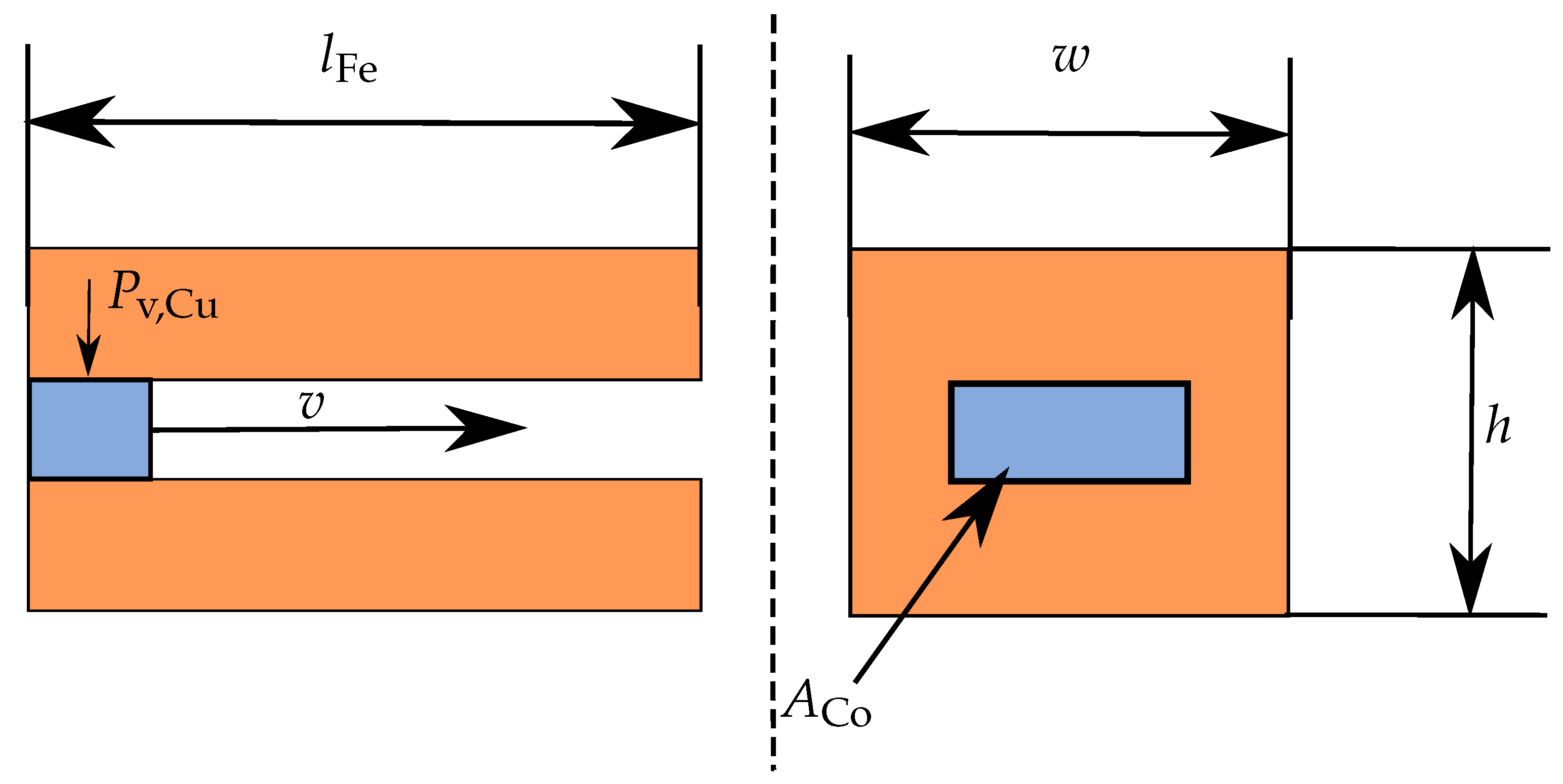
3.1. Theoretical Foundation for the Electric Motor and the Direct-Liquid-Cooled Coil Design

A direct drive concept was chosen for the electric motor drive of the propeller to reduce the complexity of the system and to avoid the additional mass and losses associated with a gearbox. Thus, the rotational speed is determined by the propeller, and an increase in power density follows an increase in torque density. Derived from the Maxwell stress tensor [11], Equation (1) gives the torque
M = π D i , 1 2 4 l Fe 1 μ 0 B ^ r , p · B ^ t , p · cos φ t , p φ r , p
and its dependence on the geometric parameters stator inner diameter D i and active length l Fe , the tangential fundamental flux B ^ t , p density simplified originating from the rotor and the radial fundamental flux density B ^ r , p originating from the stator that can be written as
B ^ r , p = A ^ p · μ 0 D i , 1 δ 2 p .
With the electric loading
A ^ p = 2 2 ξ p m w · I 1 π D i , 1
where the parameter winding factor ξ p and number of turns w are dependent on the configuration of the winding, and have no significant optimization potential with respect to electric loading. The stator current has the highest potential for increasing the electric loading and therefore the torque without any direct increase in mass. A parasitic mass increase results from the non-optimal conversion of the electric energy into mechanical energy. Accordingly, any degradation in efficiency and therefore any rise in losses leads to an increase in mass in the form of energy storage mass. The largest part of losses are the Joule losses
P v , Cu = I 1 2 · R 1 · m
with the electric resistance
R 1 = n L · N 1 · w sp · ( l Fe + l wk ) m 1 · A Cu · κ · a 2
which can be calculated from the winding parameters: number of winding layers n L , number of slots N 1 , number of turns per coil w sp , lengths of the conductor inside the stator core l Fe and end winding l wk , number of phases m 1 , conductivity κ and number of parallel strands a. Particularly noteworthy in the scope of this publication is the conductive cross-sectional area A Cu . An increase in this area reduces the losses while the current remains the same. A measure that describes the relationship between the slot cross-sectional area A Sl and conductive area is the copper fill factor
k Cu = A Cu A Sl
which is conventionally defined by the insulation material in the slot and the coating of the conductors but is also strongly influenced by the cooling channels. The cooling channels are required to keep the winding temperature below the permissible winding temperature even at high losses. The resistance
R 1 ( ϑ ) = R 1 , 20   ° C ( 1 + α Δ ϑ )
also has a dependency on the temperature represented by the coefficient α Cu = 3.9 × 10 3 K 1 . However, the cooling channels reduce the copper cross-sectional area. Therefore, the cooling channels are chosen to be as small as possible. With a smaller cooling channel cross-section A Co , the thermal capacity of the fluid moving through the cooling channel is reduced. This leads to a faster increase in fluid temperature along the conductor. This increase in temperature is dependent on the coolant flow velocity v since this has an impact on the fluid’s time t inside the conductor, the cooling channel cross-sectional area and the length of the electric motor, as shown in Figure 2. For the increase in the fluid temperature
Δ ϑ Fl = P v , Cu m Fl · c p · t
adiabatic heating is assumed. For the adiabatic heating, the Joule losses P v , Cu , the mass m Fl and the specific thermal capacity c p of the coolant are used. The calculation was performed in mm steps for the length of the conductor. The coolant flow temperature for the next step is defined by the heating in the previous step with the logarithmic temperature difference Δ ϑ log . However, this process must be repeated several times with the help of an iterative loop because the temperature rise affects the resistance and therefore the losses described by Equation (7) and thus the heating of the conductor and the temperature of the coolant.
In summary, the calculation method is presented in Table 1. The increase of the cooling channel and therefore the adjustment of the cooling channel is superimposed and not shown in detail.
The heat-transfer mechanism considered is forced convection inside the conductor. Heat conduction from the stator core to the conductors and natural convection at the end winding is neglected.
A higher coolant flow velocity enables better heat transfer which is shown by the heat-transfer coefficient h. For the coolant water, the relationship between the flow velocity and the heat-transfer coefficient
h = 580 W m 2 K + 2100 W m 2 K · v ms 1 0.5
from [12] is used. A higher heat-transfer coefficient requires a smaller cross-section for the heat transfer from the conductor to the coolant and therefore allows a higher copper fill factor k Cu . However, with a higher coolant velocity, the pressure drop as shown for the heat exchanger (Equation (14)) also increases and with it the pump power. The total mass of the drive system
m T = m CS + m EM + m ES
consists of the cooling system mass m CS , the mass of the electric motor m EM and the energy storage m ES .

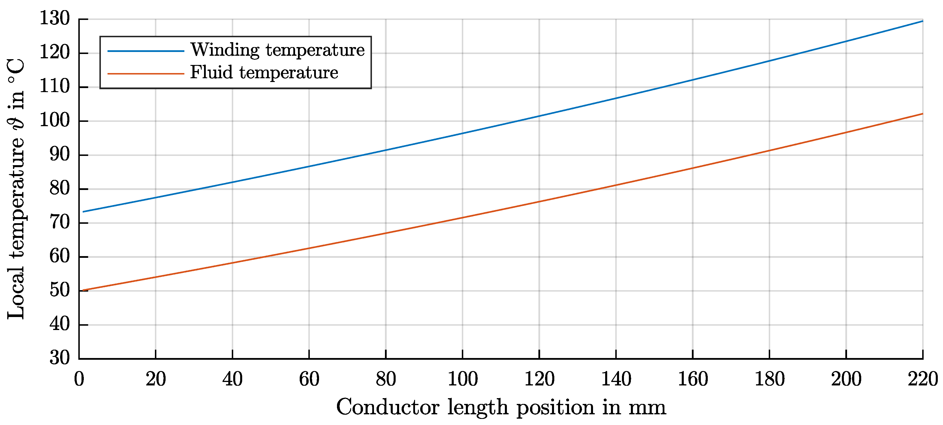
3.2. Theoretical Fundamentals of the Heat Exchanger and Pump

The heat exchanger serves to dissipate the heat losses to the environmental air as the main heat sink for the all-electric aircraft. A conventional counter-crossflow finned tube heat exchanger with a staggered tube arrangement is chosen for this research, since this type of heat exchanger has been widely explored for all kind of applications, so the mathematical modeling approaches and the underlying experimental correlations have been validated extensively. Beside supporting the structural arrangement of the tubes, fins are used to increase the outer surface area to compensate for the lower heat-transfer coefficient of the air flow compared to liquid flow inside the tubes [13]. If both the fin and tube pitch are chosen sufficiently small, the heat exchanger is considered to be compact with a surface area density above 700 m 2 / m 3 [14].
The sizing of the heat exchanger is performed by means of the cell method [15] along the flow direction of the coolant, as shown in the sketch of Figure 3. The transferred heat flow in each cell is calculated by Equation (11) by means of the product of overall heat-transfer coefficient and heat-transfer area U A and the mean temperature difference between coolant and air Δ T m .
Q ˙ = U A · Δ T m
As is apparent from the equation, it is favourable to increase the overall heat-transfer coefficient and also the mean temperature difference to achieve high heat flow rates and thus to design a compact and lightweight heat exchanger. The overall heat-transfer coefficient is described by the thermal resistances for the coolant flow inside the tubes, the tube walls and the air flow outside the tubes.
1 U A = 1 h i · A i + ln d o / d i 2 · π · λ tube + 1 h o · ( A tube + η fin · A fin )
For the outer air flow, the fin efficiency η fin accounts for the thermal conductivity of the fins. Its derivation and underlying equations can be found in [16].
The heat-transfer coefficients are derived from experimentally obtained Nusselt correlations N u , the thermal conductivity of the fluid λ and the hydraulic diameter d hyd .
h = N u · λ d hyd
The heat transfer is enhanced by choosing a small hydraulic diameter, which is the inner tube diameter for the inner heat-transfer coefficient and the fin pitch for the outer heat-transfer coefficient. The Nusselt number of the coolant flow is calculated using the correlations for pipe flow of Gnielinski [17], while for the air-side Nusselt number, the correlation of Mihailović et al. [18] is used.
However, the hydraulic diameter cannot be reduced arbitrarily since the pressure loss rises in turn. This is shown as an example by Equation (14) for the coolant pipe flow with a given mass flow rate.
Δ p = 8 · ξ · l tube · m ˙ 2 π 2 · d i 5 · ρ
The drag coefficient ξ depends on the Reynolds number, as shown in [19] for pipe flow, and as shown by Marković et al. [20] for air flow around staggered finned tubes.
The pressure losses experienced by the coolant inside the heat exchanger and inside the electric motor cause a rise in the required pumping power and thus an increase in energy storage mass, whereby all additional losses within the pump are described by its efficiency η p .
P p = 1 η p · V ˙ · Δ p Fl
The weight of the additional process system components piping, valves and control units is small compared to the heat exchanger and pump and is thus neglected.

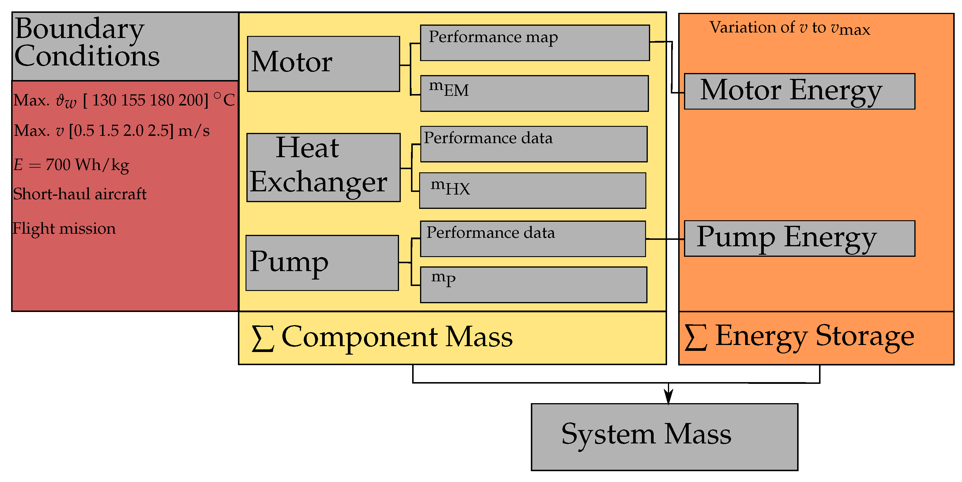
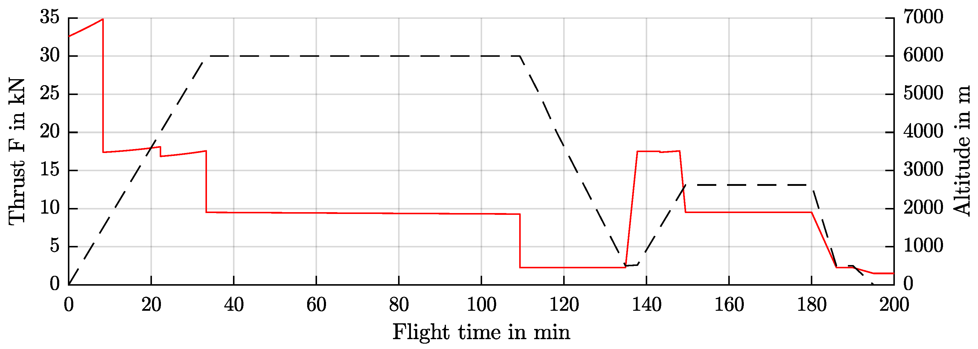
4. Boundary Conditions of the Investigation

A regional short-haul aircraft was selected to provide the boundary conditions for the investigation. The flight mission is shown in Figure 4. This flight mission is used for the investigation of the ideal operating strategy for the cooling system and the evaluation of the overall mass. The aircraft is comparable to the ATR-72 with 78 seats, a flight distance of 1000 km and a maximum take-off weight of about 23,000 kg. The maximum payload is designed to be 7400 kg.
The heat exchanger air velocity cannot be set equal to the aircraft velocity since the air-side pressure drop across the heat exchanger would be too large. Typically, a diffuser is used in a ram air duct upstream for the heat exchanger to recover most of the dynamic pressure while reducing the air velocity. For practical purposes, the flow velocity is set to 20 m/s as described in [21]. Since the trade-off in the electric motor’s power density and efficiency is dependent on the energy storage density, a comparable system architecture as presented in [22] is set up. The energy storage density hereby corresponds to 700 Wh/kg. The details of the electric motor can be found in Table 2.

5. Cooling System Architecture

The cooling system for the aircraft’s two propulsion units are isolated from each other. Each electrical conductor has its own cooling channel, as shown in Figure 5. The cooling channels are all connected in parallel to have a minimum pressure drop. The end of the cooling channels is located in the end winding area which is flooded with cooling fluid. The inlet is constructed identically. A carbon tube prevents the liquid from coming into contact with the rotor. Below the motor, the heat exchanger is located in a ram air duct. As is also the case with conventional turboprop engines. This also allows very short coolant pipelines. The cooled fluid is drawn in by the pump and immediately flows back into the motor cooling system.

6. Design of System Components

The component design is based on the worst-case conditions, a hot day take-off as specified in the MIL STD 210A Hot Atmosphere Standard, which is also described in [23], and a take-off altitude of 2000 m. The introduced equations with the boundary conditions of the following sections are solved using MATLAB.

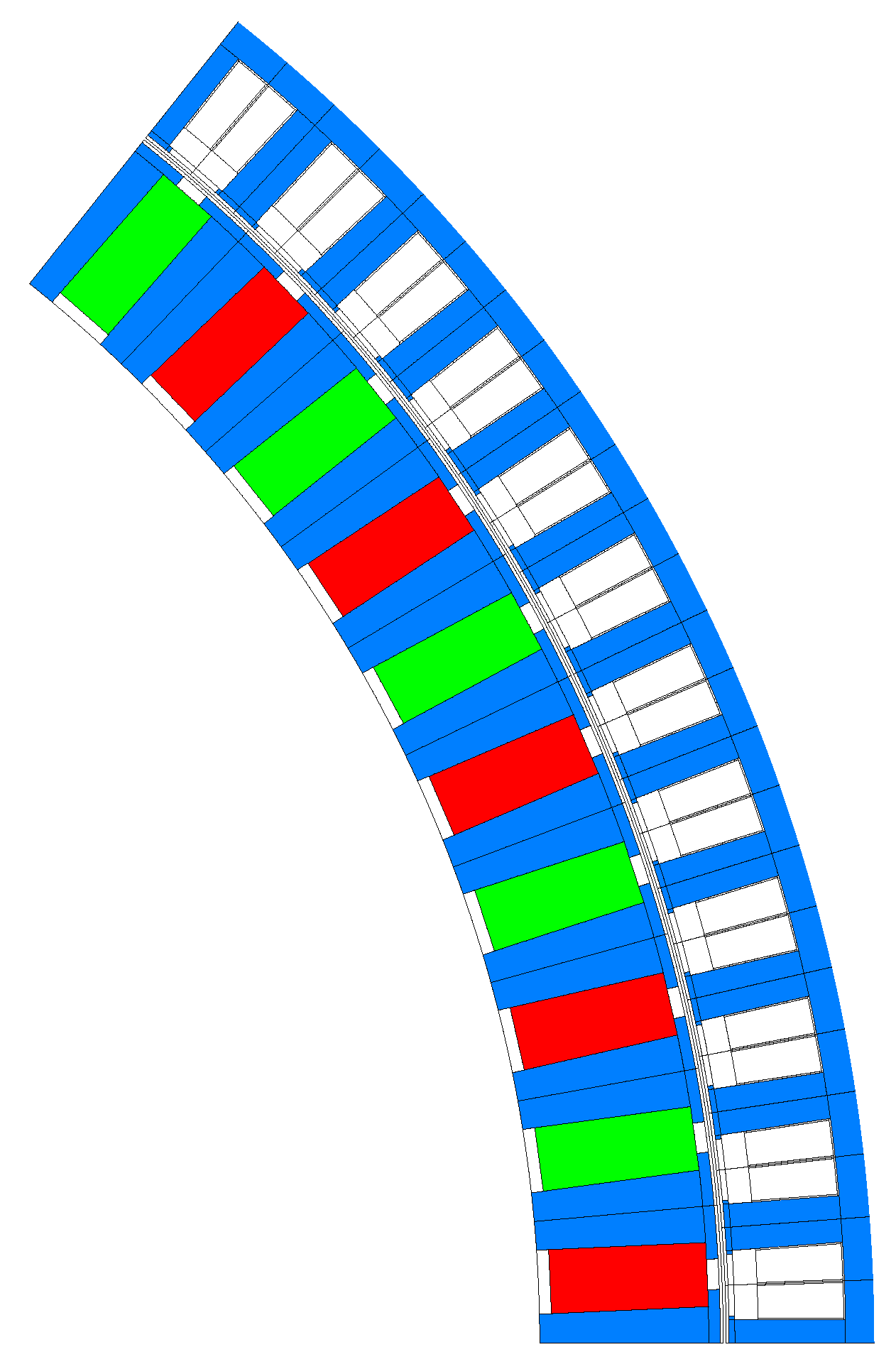
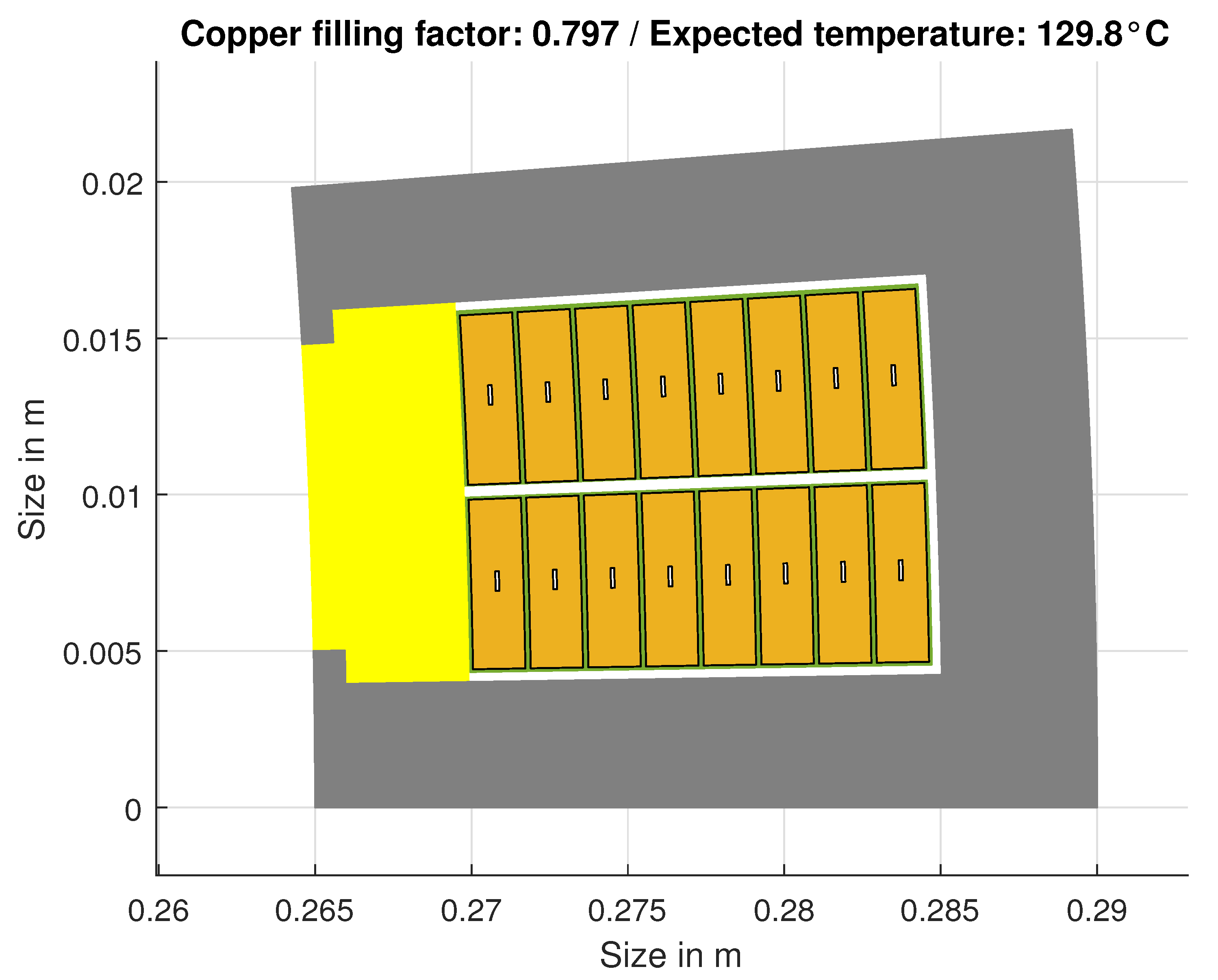
6.1. Electric Motor Design Constraints

The electric motor is designed for take-off power output. For this purpose, the thrust was converted using a propeller design into a torque-speed characteristic by a method described in [24]. The maximum power for one motor is given by P = 1760 kW with a maximum rotational speed of n = 1400 min 1 , the maximum torque requirement is M = 12 kNm . The winding is designed as a fractional-slot concentrated winding with directly liquid-cooled coils. The slot insulation is set to 0.25 mm, while the coating thickness of the wire insulation is set to 85 µm. These values are based on the standard [25]. The current density is set to J = 25 A/mm 2 , which leads to an optimum in overall mass for the same aircraft as in [26]. The initially chosen copper fill factor is set to k Cu = 0.75.
Using the electromagnetic design in Table 2, post-processing of the FEA results is carried out in 20 different variants that are combinations from maximum winding temperatures ϑ w , max [130 155 180 200] ° C and maximum coolant velocities v max [0.50 1.00 1.50 2.00 2.50] ms 1 . The FEA was carried out with the help of the software FEMAG and Matlab as post-proceccing software. A Cross-section is shown in Figure 6.

6.2. Heat Exchanger Design Constraints

The heat exchanger is sized as a counter-crossflow finned tube heat exchanger similar to that used in the study conducted in [27] with the underlying equations introduced in Section 3.2. The required heat flow to be transferred from coolant to air is defined by the efficiency of the electric motor dictated by its design. The coolant inlet temperature of the heat exchanger likewise depends on the electric motor design as it depends on the maximum permitted temperature. The desired outlet temperature of the coolant is set to 50   ° C and the mass flow rate can be calculated as
m ˙ = Q ˙ c p · ( T in T out ) .
The width of the heat exchanger is set to 400 mm to enable possible mounting underneath the electric motor. Its height is given by a defined number of vertical tube rows, which is varied between 5 and 15. For each number of vertical tube rows, the required number of horizontal tubes in the connected tube row is calculated as a measure of the heat exchanger depth needed to dissipate the prescribed heat flow to the air, as shown in Figure 3. The inner tube diameter is determined iteratively to match a desired coolant pressure loss within the heat exchanger of 0.5 bar. The most lightweight combination of vertical and horizontal tube numbers is chosen as the final heat exchanger design.
The remaining geometric parameters are kept constant during the heat exchanger design procedure, since the primary emphasis in this research is placed on the electric motor design. However, the parameters were previously chosen driven by the objective to achieve a lightweight and compact heat exchanger design in general with a reasonable air-side pressure loss. All parameters are summarized in Table 3.

6.3. Pump Design Constraints

The pump is a simplified model with a constant efficiency at a given power. The efficiency of the pump including the driving electric motor is derived from [29] at η p = 30 % . The power density is based on the Pierburg CWA 400 pump used in the automotive sector at 0.25 kW/kg including the electric motor. Water with an absolute pressure of 3 bar upstream of the pump is selected as the coolant to allow temperatures above 100 ° C without evaporation.

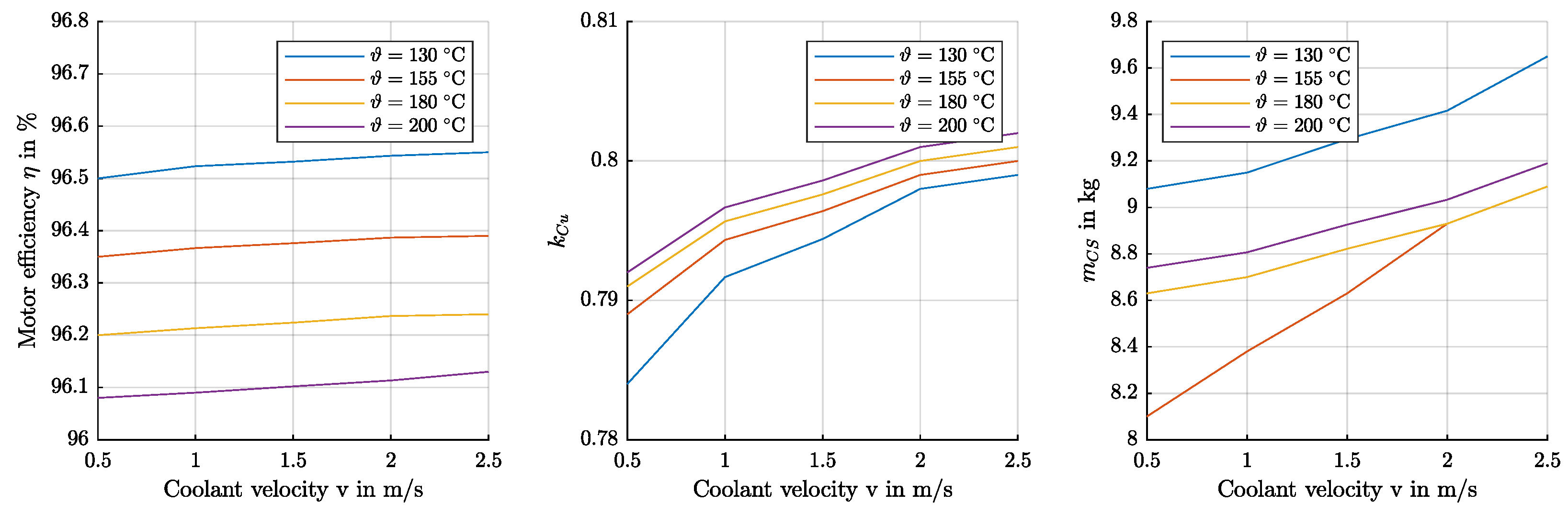
6.4. Comparison of System Components at Maximum Load

The impact of varying the maximum winding temperature and maximum coolant velocity on motor efficiency, the copper filling factor and the cooling system mass (pump and heat exchanger) is shown in Figure 7. It can be seen that the motor with the lowest winding temperature has the highest efficiency. Compared to the other models, the difference is rather small due to the higher possible copper filling factors at higher permissible winding temperatures. For the cooling system mass, the motor with a maximum winding temperature of ϑ w = 155 ° C shows the lowest values due to a good trade-off between the pressure loss of the components and overall losses to be dissipated to the environment.
Figure 8 shows the temperature calculated with the proposed method in Section 3. The Figure shows that a large temperature gradient appears, since the fluid temperature rise is large due to a restricted pressure drop across the cooling channels of the electric motor. There is a presumption that mechanical stresses occur in the conductor with too large temperature gradients. One solution could be to induce two-phase operation through flow boiling (liquid and gaseous phase of the fluid). Flow boiling takes place at constant fluid temperature and gradients in the winding temperature can only occur due to varying heat-transfer coefficients with vapor quality. The potential of two-phase cooling with respect to lower thermal gradients in electrical components has been demonstrated in [30]. With the aspect ratio of the cooling channel, the temperature rise of the fluid can be adjusted to a certain extent. A cooling channel with a high width and low height favors a two-phase flow of the fluid due to a high cross-section that transfers the heat to the fluid. The overall fluid mass inside the conductor is reduced too, which is also advantageous for the two-phase flow.

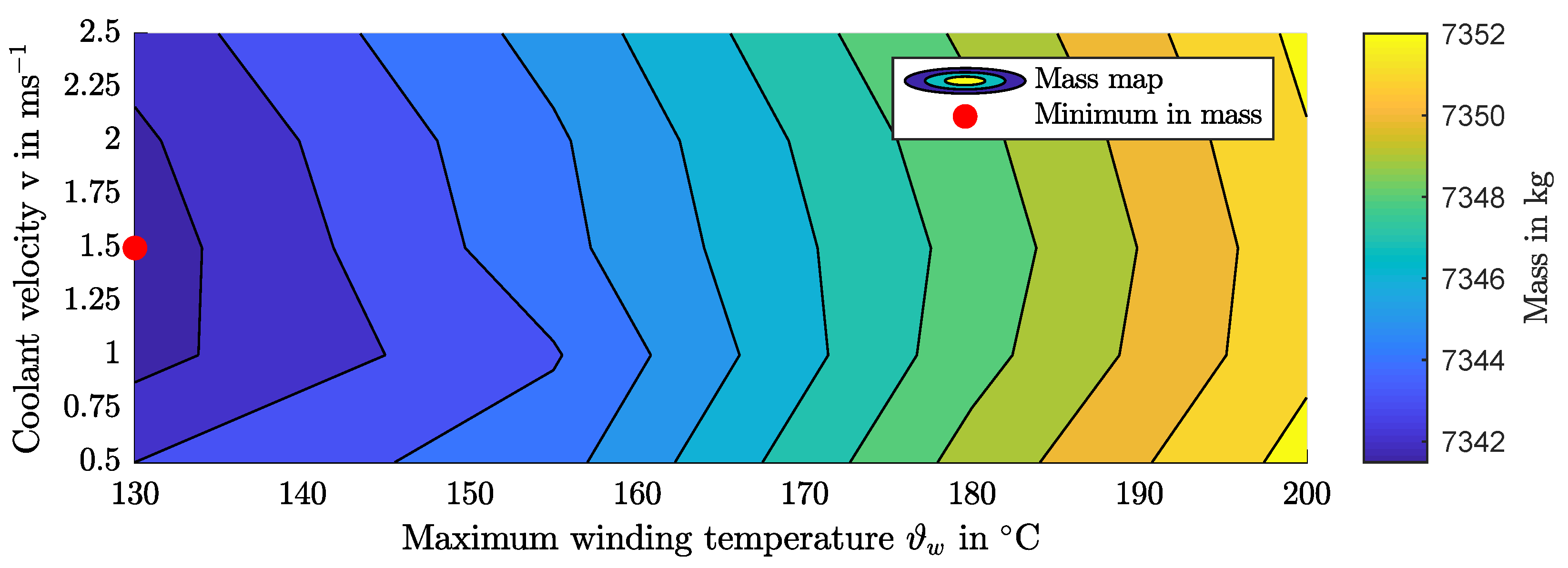
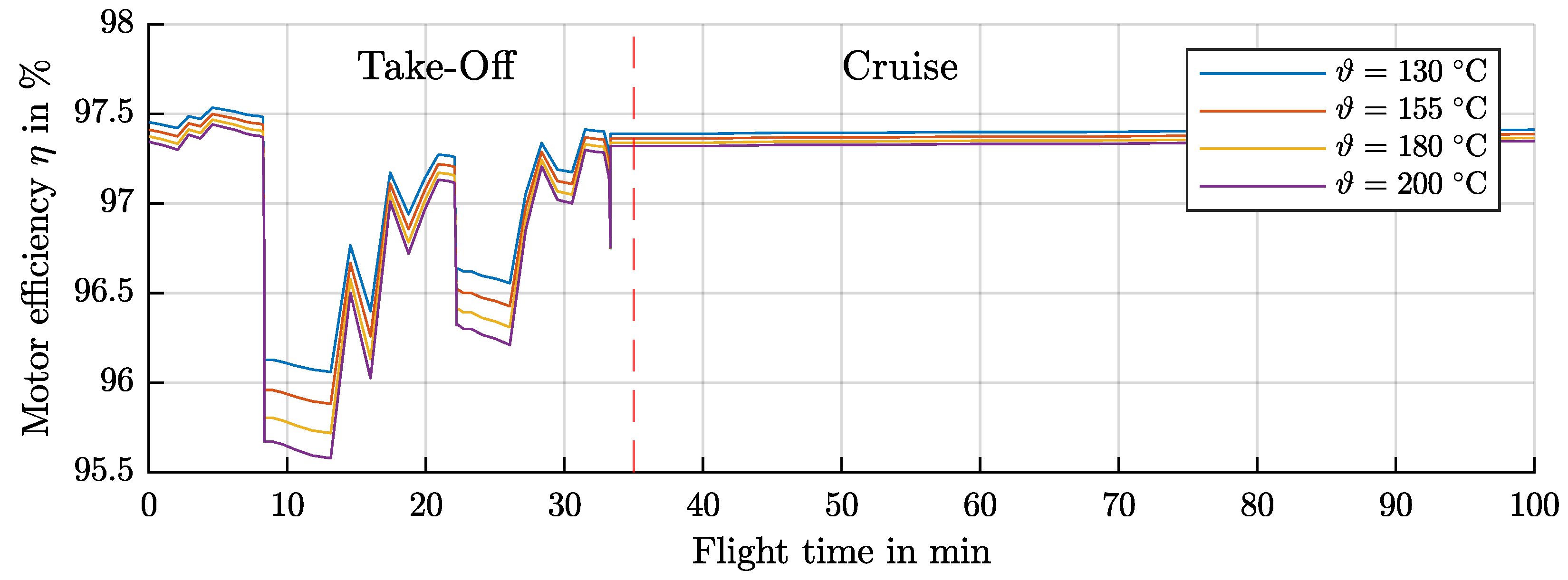
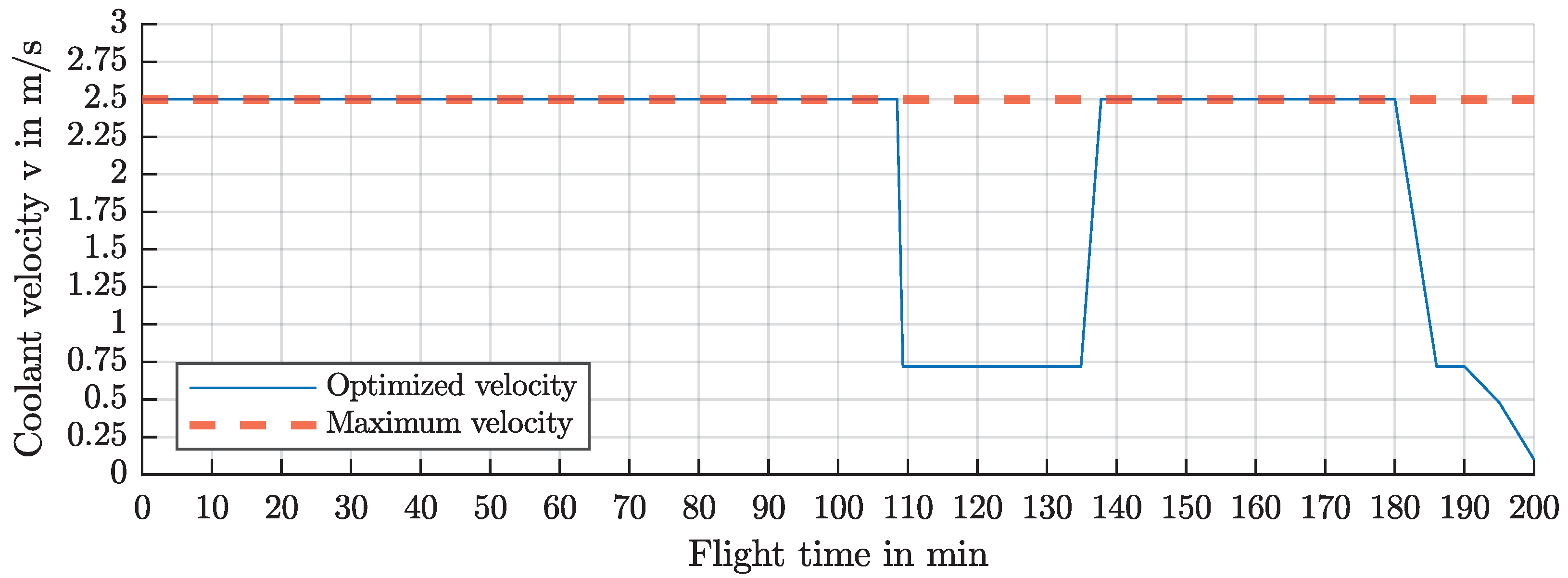
7. Optimization of Cooling System Operation Strategy

The optimization of the cooling system operation includes variation in the coolant flow velocity from 0.1 m/s up to the maximum flow velocity for which the cooling channel is sized. This must be done for each operating point of the flight mission and for every maximum winding temperature. Finally, it can be determined which flow rate the pump must provide to allow minimum energy consumption in the overall drive system.
Figure 9 shows a map of the total powertrain mass for maximum winding temperature and the maximum coolant velocity. It can be seen that the temperature influences the overall mass more than the coolant velocity. It can also be seen that low coolant velocities are disadvantageous since the heat transfer is lower and therefore the copper cross-section is smaller, which leads to higher losses and therefore to increased mass of the energy storage. A high coolant velocity leads to higher pump energy consumption, but since the pump power is rather low, the impact is small. For the specified system, the optimum is located at ϑ max , w = 130 ° C and v max = 1.5 ms 1 . Table 4 shows the details of this design point.
The changes in total mass across the considered parameter range are very small. This is due to the low maximum current density and the associated high efficiency as well as the existence of two compensating effects. Choosing a high winding temperature results in small cooling channels and thus in a large copper cross-section, and vice versa, which is shown in Figure 7. This causes the efficiencies in partial load operation (cruise) to be very close to each other, that is shown in Figure 10.
When operating the pump at every operating point for different operation points, it becomes apparent that the coolant speed in the cooling channel should only be reduced in the descent flight phase at low power output as shown in Figure 11.

8. Discussion and Conclusions

The research question of this publication was, which maximum winding temperature and which maximum coolant velocity lead to an overall minimum in the mass of the powertrain of an electric aircraft? Additionally, the question of the optimum control of the cooling system was asked, especially regarding control of the coolant velocity inside the cooling channels of the electric motor. It was found that both the mass of the heat exchanger and the mass of the pump and the necessary energy storage for the operation of the pump are negligible when optimizing the mass of the overall powertrain. For electric motors with higher utilization and higher current density, greater losses occur, so it is assumed that the components are more important in this scenario. With regard to the operation of the cooling system, it has been shown that it is advantageous to keep the coolant speed at its maximum at almost all operating points in order to reduce the temperature of the winding of the electric motor as much as possible.
The main topics and findings of this publication are as follows:
  • The mass of the heat exchanger and pump is negligible when optimizing the mass of the powertrain compared to the mass of the energy storage and the mass of the electric motor.
  • The impact of the maximum winding temperature ϑ max , w on the efficiency and mass of the powertrain is investigated.
  • The choice of the maximum winding temperature does not have a large effect on the efficiency and thus on the total mass when the electric motor is not utilized very intensively.
  • A simplified calculation method for conductor heating and fluid heating for directly liquid-cooled windings is presented.
  • The results suggest that two-phase cooling offers further advantages over single-phase cooling due to presumably lower temperature gradients. This represents an opportunity for future research.

Author Contributions

Formal analysis, R.J.K., F.N., M.N. and E.K.; Writing—review & editing, S.K. and B.P. All authors have read and agreed to the published version of the manuscript.

Funding

This research was funded by the Deutsche Forschungsgemeinschaft (DFG, German Research Foundation) under Germany’s Excellence Strategy EXC 2163/1. Sustainable and Energy Efficient Aviation Project ID 390881007. https://www.tu-braunschweig.de/se2a (accessed on 1 January 2019).

Data Availability Statement

The most important data are included in tables and the method is described so that no additional data are available.

Conflicts of Interest

The authors declare no conflict of interest.

References

  1. Sixel, W.; Liu, M.; Nellis, G.; Sarlioglu, B. Cooling of Windings in Electric Machines via 3D Printed Heat Exchanger. In Proceedings of the 2018 IEEE Energy Conversion Congress and Exposition (ECCE), Portland, OR, USA, 23–27 September 2018; pp. 229–235. [Google Scholar] [CrossRef]
  2. Sixel, W.; Liu, M.; Nellis, G.; Sarlioglu, B. Ceramic 3D Printed Direct Winding Heat Exchangers for Improving Electric Machine Thermal Management. In Proceedings of the 2019 IEEE Energy Conversion Congress and Exposition (ECCE), Baltimore, MD, USA, 9 September–3 October 2019; pp. 769–776. [Google Scholar] [CrossRef]
  3. Wu, F.; EL-Refaie, A.M.; Al-Qarni, A. Additively Manufactured Hollow Conductors Integrated With Heat Pipes: Design Tradeoffs and Hardware Demonstration. IEEE Trans. Ind. Appl. 2021, 57, 3632–3642. [Google Scholar] [CrossRef]
  4. Petrov, I.; Lindh, P.; Niemelä, M.; Scherman, E.; Wallmark, O.; Pyrhönen, J. Investigation of a Direct Liquid Cooling System in a Permanent Magnet Synchronous Machine. IEEE Trans. Energy Convers. 2020, 35, 808–817. [Google Scholar] [CrossRef]
  5. Wohlers, C.; Juris, P.; Kabelac, S.; Ponick, B. Design and direct liquid cooling of tooth-coil windings. Electr. Eng. 2018, 100, 2299–2308. [Google Scholar] [CrossRef]
  6. Dong, T.; Zhu, C.; Zhou, F.; Zhang, H.; Lu, F.; Zhang, X. Innovated Approach of Predictive Thermal Management for High-Speed Propulsion Electric Machines in More Electric Aircraft. IEEE Trans. Transp. Electrif. 2020, 6, 1551–1561. [Google Scholar] [CrossRef]
  7. Yoon, M.; Jeon, C.; Kauh, S. Efficiency increase of an induction motor by improving cooling performance. IEEE Trans. Energy Convers. 2002, 17, 1–6. [Google Scholar] [CrossRef] [PubMed]
  8. Woodworth, A.A.; Smith, A.; Jansen, R.; Szpak, G. Select Variables Affecting Thermal System Design of a Liquid-Cooled Stator. In Proceedings of the 2020 AIAA/IEEE Electric Aircraft Technologies Symposium (EATS), New Orleans, LA, USA, 26–28 August 2020; pp. 1–8. [Google Scholar]
  9. Bobba, D.; Yao, Z.; Swanke, J.; Mandel, R.; McCluskey, P.; Jahns, T.; Sarlioglu, B. Multi-Physics Based Analysis and Design of Stator Coil in High Power Density PMSM for Aircraft Propulsion Applications. In Proceedings of the 2021 AIAA/IEEE Electric Aircraft Technologies Symposium (EATS), Virtual, 11–13 August 2021; pp. 1–9. [Google Scholar]
  10. Deisenroth, D.C.; Ohadi, M. Thermal management of high-power density electric motors for electrification of aviation and beyond. Energies 2019, 12, 3594. [Google Scholar] [CrossRef] [Green Version]
  11. Müller, G.; Ponick, B. Theor. Elektr. Maschinen, 6., völlig neu bearb. aufl. ed.; Wiley-VCH: Weinheim, Germany, 2009; Volume 3. [Google Scholar]
  12. Herr, H.H. Wärmelehre, 4th ed.; Technische Physik, Verl. Europa-Lehrmittel: Haan-Gruiten, Germany, 2006; Volume 3. [Google Scholar]
  13. Kays, W.M.; London, A.L. Compact Heat Exchangers, 3rd ed.; Krieger Publishing Company: Melbourne, FL, USA, 1998. [Google Scholar]
  14. Shah, R.K.; Sekulić, D.P. Fundamentals of Heat Exchanger Design; John Wiley & Sons: New York, NY, USA; Chichester, UK, 2003. [Google Scholar]
  15. Roetzel, W.; Spang, B. C1 Thermal Design of Heat Exchangers. In VDI Heat Atlas; Springer: Berlin/Heidelberg, Germany, 2010; pp. 31–66. [Google Scholar] [CrossRef]
  16. Schmidt, K.G. M1 Heat Transfer to Finned Tubes. In VDI Heat Atlas; Springer: Berlin/Heidelberg, Germany, 2010; pp. 1271–1278. [Google Scholar] [CrossRef]
  17. Gnielinski, V. G1 Heat Transfer in Pipe Flow. In VDI Heat Atlas; Springer: Berlin/Heidelberg, Germany, 2010; pp. 691–700. [Google Scholar] [CrossRef]
  18. Mihailović, M.; Milovančević, U.; Genić, S.; Jaćimović, B.; Otović, M.; Kolendić, P. Air side heat-transfer coefficient in plate finned tube heat exchangers. Exp. Heat Transf. 2019, 33, 388–399. [Google Scholar] [CrossRef]
  19. Kast, W.; Gaddis, E.S.; Wirth, K.E.; Stichlmair, J. L1 Pressure Drop in Single Phase Flow. In VDI Heat Atlas; Springer: Berlin/Heidelberg, Germany, 2010; pp. 1053–1116. [Google Scholar] [CrossRef]
  20. Marković, S.; Jaćimović, B.; Genić, S.; Mihailović, M.; Milovančević, U.; Otović, M. Air side pressure drop in plate finned tube heat exchangers. Int. J. Refrig. 2019, 99, 24–29. [Google Scholar] [CrossRef]
  21. Wrobel, R.; Scholes, B.; Mustaffer, A.; Ullah, S.; Reay, D.; Mecrow, B.; Hussein, A. Design and Experimental Characterisation of an Additively Manufactured Heat Exchanger for the Electric Propulsion Unit of a High-Altitude Solar Aircraft. In Proceedings of the 2019 IEEE Energy Conversion Congress and Exposition (ECCE), Baltimore, MD, USA, 29 September–3 October 2019; pp. 753–760. [Google Scholar] [CrossRef] [Green Version]
  22. Ebersberger, J.; Keuter, R.J.; Ponick, B.; Mertens, A. Power Distribution and Propulsion System for an All-Electric Regional Aircraft. In Proceedings of the 2023 IEEE International Conference on Electrical Systems for Aircraft, Railway, Ship Propulsion and Road Vehicles & International Transportation Electrification Conference (ESARS-ITEC), Venice, Italy, 29 March 2023; pp. 1–7. [Google Scholar] [CrossRef]
  23. Soares, C. Chapter 19—Basic Design Theory. In Gas Turbines, 2nd ed.; Soares, C., Ed.; Butterworth-Heinemann: Oxford, UK, 2015; pp. 913–958. [Google Scholar] [CrossRef]
  24. Keuter, R.J.; Kirsch, B.; Friedrich, J.; Ponick, B. Design Decisions for a Powertrain Combination of Electric Motor and Propeller for an Electric Aircraft. IEEE Access, 2023; accepted in IEEE Access 2023-07. [Google Scholar]
  25. IEC 60317-0-2:2020; Specifications for Particular Types of Winding Wires—Part 0-2: General Requirements—Enamelled Rectangular Copper Wire. 2020. Available online: https://webstore.iec.ch/publication/63495 (accessed on 3 July 2023).
  26. Ebersberger, J.; Fauth, L.; Keuter, R.; Cao, Y.; Freund, Y.; Hanke-Rauschenbach, R.; Ponick, B.; Mertens, A.; Friebe, J. Power Distribution and Propulsion System for an All-Electric Short-Range Commuter Aircraft—A Case Study. IEEE Access 2022, 10, 114514–114539. [Google Scholar] [CrossRef]
  27. Schiltgen, B.T.; Freeman, J. Aeropropulsive Interaction and Thermal System Integration within the ECO-150: A Turboelectric Distributed Propulsion Airliner with Conventional Electric Machines. In Proceedings of the 16th AIAA Aviation Technology, Integration, and Operations Conference. American Institute of Aeronautics and Astronautics, Washington, DC, USA, 13–17 June 2016. [Google Scholar] [CrossRef]
  28. Tahseen, T.A.; Ishak, M.; Rahman, M. An overview on thermal and fluid flow characteristics in a plain plate finned and un-finned tube banks heat exchanger. Renew. Sustain. Energy Rev. 2015, 43, 363–380. [Google Scholar] [CrossRef] [Green Version]
  29. Watter, H. Hydraulik und Pneumatik: Grundlagen und Übungen—Anwendungen und Simulation, 2. überarbeitete aufl., ed.; Studium, Vieweg+Teubner Verlag/GWV Fachverlage, Wiesbaden: Wiesbaden, Germany, 2008. [Google Scholar]
  30. Wang, P.; McCluskey, P.; Bar-Cohen, A. Two-Phase Liquid Cooling for Thermal Management of IGBT Power Electronic Module. J. Electron. Packag. 2013, 135, 4023215. [Google Scholar] [CrossRef]
Figure 1. Flow chart of the investigation process for this publication.
Energies 16 05319 g001
Figure 2. Sketch of the conductor with a cooling channel. (Left): Longitudinal section. (Right): Cross-section.
Energies 16 05319 g002
Figure 3. Sketch of the modeling principle for the heat exchanger based on the cell method. (Left): A single connected tube row. (Right): A single control volume of the discretized tube row.
Energies 16 05319 g003
Figure 4. Flight mission of the short-haul aircraft.
Energies 16 05319 g004
Figure 5. Cross-section of the electric motor with the specifications shown in Table 2.
Energies 16 05319 g005
Figure 6. Design of the cooling channels for the maximum winding temperature of ϑ w , max = 130 ° C and the coolant speed of v max = 1.5 m/s.
Energies 16 05319 g006
Figure 7. Impact of coolant velocity v and maximum winding temperature ϑ w on the motor efficiency, copper filling factor and mass of the cooling system.
Energies 16 05319 g007
Figure 8. Local temperatures of the winding and the coolant along the conductor with the configuration ϑ w , max = 130 °C and v max = 1.5 m/s.
Energies 16 05319 g008
Figure 9. Optimized mass against maximum winding temperature and maximum coolant velocity of the motor, heat exchanger, pump and energy storage for the flight mission.
Energies 16 05319 g009
Figure 10. Comparison of the efficiencies at different maximum winding temperatures during the flight mission.
Energies 16 05319 g010
Figure 11. Coolant velocity in the motor cooling channel compared to the maximum coolant velocity throughout the flight mission.
Energies 16 05319 g011
Table 1. Calculation procedure for winding and fluid temperature performed for the entire conductor length in 1 mm steps.
StepEquationExplanation
1 t = l Fe / v Time of the fluid inside the conductor
2 A Cu = w · h A Co Copper cross-section of one conductor
3 U = 2 · h CC + 2 · w CC Fluid wetted inside the conductor
4 R 20   ° C = l Fe / ( A Cu · κ Cu ) Electric resistance of one conductor
5 P v , Cu = I 2 · R ( ϑ w ) Joule losses of the conductor
6 ϑ Fl = P v m Fl · c p · t + ϑ i Heating of the cooling fluid
7 Δ ϑ log = P v U · l Fe · h Logarithmic temperature difference
8 Δ ϑ log = ϑ i ϑ o ϑ w ϑ i ϑ w ϑ o Solving for the winding temperature ϑ w
9 R ( ϑ w ) = R 20   ° C ( 1 + α ( ϑ w 20   K ) ) Correction of resistance/start of the first iteration
Table 2. Design constraints and results of the electromagnetic design of the motor.
ParameterSymbolValue
Outer diameter D a , 1 580 mm
Inner diameter D i , 1 530 mm
Number of pole pairsp35
Air gap σ 1.5 mm
Core length l Fe 220 mm
Maximum frequency f 1 816.6 Hz
Power factor cos φ 0.81
Power density Π 11.91 kW/kg
Torque density Π T 81.22 Nm/kg
Massm147.80 kg
Rated voltage U 1 1275 V
Rated current I 1 1025 A
Parallel strandsa5
Number of turns per coil w sp 8
Table 3. Design constraints for the heat exchanger based on [28].
ParameterSymbolValue
Coolant outlet temperature ϑ Fl , out 50 ° C
Air inlet temperature ϑ air , in 40 ° C
Air outlet temperature ϑ air , out 60 ° C
Material-Aluminum
Width w HX 400 mm
Fin pitch s fin 1.67 mm
Fin thickness δ fin 0.15 mm
Tube wall thickness δ tube 0.5 mm
Coolant pressure loss Δ p Fl 0.5 bar
Table 4. Mass overview of optimal design.
ComponentMass in kg
Motor2 × 147.80 kg
Heat exchanger2 × 8.95 kg
Pump2 × 0.30 kg
Energy storage7028 kg
7342 kg
Disclaimer/Publisher’s Note: The statements, opinions and data contained in all publications are solely those of the individual author(s) and contributor(s) and not of MDPI and/or the editor(s). MDPI and/or the editor(s) disclaim responsibility for any injury to people or property resulting from any ideas, methods, instructions or products referred to in the content.

