1. Introduction
Most applications of permanent magnet direct drive servo motors require high precision. For example, the positioning accuracy of aerospace equipment generally needs to reach arc-second level or even sub-arc-second level [
1,
2]. For the space optical communication turntable, the speed should be a few tenths of a degree per second, and the stability should be about 2.5% [
3]. This requires higher-precision position measurement components, but the improvement of sensor accuracy often increases the product volume, the processing difficulty and the manufacturing cost. Moreover, due to the influence of quantization error and limited detection accuracy, the calculation of position/speed at ultra-low speed often has problems of large errors and delays. Accurate feedback signals are the basis of high-performance control. If the feedback delay is large and the precision is low, the effect of the control strategy will be greatly reduced, and it will be difficult to meet the high-performance requirements of fast dynamic response and low-speed stable operation. Therefore, in order to achieve high-precision control of permanent magnet direct drive servo motors, it is necessary to conduct in-depth research on low-latency position/speed acquisition technology with limited precision.
Low-latency position/speed acquisition techniques can be mainly divided into non-model-based interpolation fitting algorithms and model-based observer methods. Interpolation fitting methods include the least square method, the average speed method and the average acceleration method, etc.
Marquette scholars in the United States proposed to use the least square method to process low-resolution position signals [
4], which improved the continuity and stability of the signal. However, when the motor starts, it is difficult to estimate the rotor position and speed effectively using this method.
Japanese scholar Morimoto proposed the average speed method [
5], and successfully applied it to the permanent magnet synchronous motor drive. Scholars at Ohio State University simplified this algorithm and implemented it through software codes [
6]. However, during the actual operation of the motor, external disturbances and torque fluctuations have a certain impact on the acceleration of the motor, resulting in large dynamic errors, and it is difficult to achieve a better closed-loop control of the motor speed. Therefore, the research team at the University of Rome in Italy proposed the average acceleration method [
7] that introduces the acceleration reference, which can effectively reduce errors and improve the accuracy of speed and position estimation. At the same time, the fitting method based on deep learning has also become a hot research topic. The literature [
8] proposed the transfer learning based on representation learning. The literature [
9] proposed a novel variational auto-encoder long short-term memory network and a local weighted deep sub-domain adaptation network. The fitting effect has been significantly increased.
Although the interpolation fitting method can improve the accuracy of the rotor position signal, there is a certain lag and noise in the speed estimation result compared with the actual speed in the control of the speed loop. Therefore, it is difficult for the difference fitting method to achieve good results in applications that require high dynamic control performance of the motor speed. Many different observer design methods have emerged under the continuous learning and innovation of scholars at home and abroad. Model-based observer methods mainly include the full-order state observer method, the extended Kalman filter method and the sliding mode observer method.
American engineer R. E. Kalman first proposed the Kalman filter, which can directly deal with random noise interference using a recursive method and has low dependence on the model [
10]. However, it has poor performance at low speeds and large observation errors. Today, the Kalman filter method has been optimized in combination with various algorithms. The literature [
11] proposed a novel adaptive approach based on the Kalman filter and the expectation maximum with Rauch–Tung–Striebel which accurately predicts the RUL of the battery. The literature [
12] proposes a novel expectation maximization unscented particle filter Wilcoxon rank sum test approach which experimental results represent as the approach that outperforms some existing data-driven methods.
Japanese scholars first proposed the sliding mode control theory. Sliding mode control does not require high accuracy of the model and has certain robustness, so it is more suitable for a permanent magnet synchronous motor control system [
13]. Since this method estimates the rotor position through the back electromotive force, the decrease in the magnitude and frequency of the back electromotive force when the speed decreases leads to a large error at low speeds [
14].
The full-order state observer uses the mathematical model of the motor to calculate the estimated value of the current state of the system through the directly measurable state of the motor. When the system model is completely accurate with the initial state, the full-order observer can estimate the system state without bias [
15]. The extended state observer improved on this basis has also been widely used. The literature [
16] proposed a nonlinear rotor position estimation method based on an extended state observer and introduced ideas such as variable structure control to improve the dynamic performance of a faulty motor without position control. The literature [
17] aimed at the problem of high-performance control of permanent magnet synchronous motors without position sensors in the full speed range and proposed a hybrid position estimation strategy based on extended state observer (ESO) load torque compensation, which improved the system’s anti-disturbance performance. The literature [
18] proposed a motor control method based on a finite-time state observer, which improved the robustness of the permanent magnet synchronous motor system and improved the problem of motor rotor position tracking performance due to load changes. The literature [
19] proposed a feedback gain design criterion to ensure the low-speed stable operation of the observer, which improved the dynamic and static performance of the sensorless vector control system in the low-speed region. The literature [
20] proposes an adaptive robust control strategy with an event trigger mechanism and an extended state observer. The extended state observer is used to estimate the velocity value and mismatched external disturbance, which improves the performance of position tracking control.
The full-order observer can use the observed motor position, speed and disturbance torque information as the feedback acquisition link of the speed control to achieve more precise control of the motor. Moreover, the observation performance of the full-order observer at low speed is better [
21,
22,
23], which is very suitable for the research of this paper.
This paper first analyzes the problems existing in the low-speed operation of the permanent magnet direct drive servo motor. Then, by analyzing the difference method, it can play a certain role in compensating the rotor position signal, but it also has certain shortcomings. When the motor speed is close to 0, the output signal of the sensor will fluctuate in a short time, which will affect the speed control accuracy. Based on the above analysis, the observer method is proposed to realize the acquisition of the position signal of the permanent magnet direct drive servo motor at low speed. Because the observer method adopts the idea of the combining system model and closed-loop control, it makes full use of the parameter information of the motor system. Therefore, the accuracy of the rotor position estimation results is improved, the stability of speed control is enhanced, and the motor control performance is significantly enhanced. This paper starts with the special structure of the direct drive motor and finds the existing position detection accuracy problem. The innovative application of the extended state observer to the rotor position estimation of the permanent magnet direct drive servo motor has produced very significant results. The position signal acquisition accuracy of the permanent magnet direct drive servo motor during low-speed operation is improved. The control stability of permanent magnet direct drive servo motors is significantly increased.
2. Motor Position Feedback Acquisition Problem at Low Speed
The traditional servo system consists of a high-speed motor plus a reduction mechanism. Because it has an intermediate reduction mechanism, the motor can still run at medium and high speeds when driving low-speed loads. However, for a direct drive servo system, when driving a low-speed load, the speed of the motor is the speed of the load. Therefore, the low-speed or ultra-low-speed operation of the motor is an important state that the direct drive servo system needs to face. For example, the laser communication following system in the aerospace servo requires the motor to rotate at a speed of 0.01 r/min or even lower; the antenna tracks the turntable, and the minimum speed of the motor reaches 0.0017 r/min. In astronomical observation, in order to overcome the influence of the earth’s rotation on the observation, the motor needs to rotate at an ultra-low speed of 1 r/24 h [
24]. This paper takes the aerospace servo system as the research object, uses a resolver suitable for harsh environments and analyzes the problems existing in the acquisition of the resolver position feedback signal in detail.
The resolver changes the primary and secondary windings by rotating the rotor, so that the output voltage changes with the rotor position. Then, the rotor position signal is obtained by solving the output voltage. After years of development, resolvers and their decoding algorithms have been integrated, represented by the AD2S series resolver decoding chips, which can provide a maximum resolution of 16 bits. When the decoding accuracy of the resolver is selected as 16 bits, its position feedback resolution is:
The speed control cycle is selected as 2 kHz. If the control speed is 0.1 r/min, the motor rotor position moves Δ
θTs in each speed control cycle
Ts:
Comparing Equations (1) and (2), it can be seen that when the control speed is 0.1 r/min, the position signal of the position sensor with 16-bit resolution remains unchanged in more than ten control cycles. This will seriously affect the speed control accuracy at low speeds and greatly weaken the controller performance.
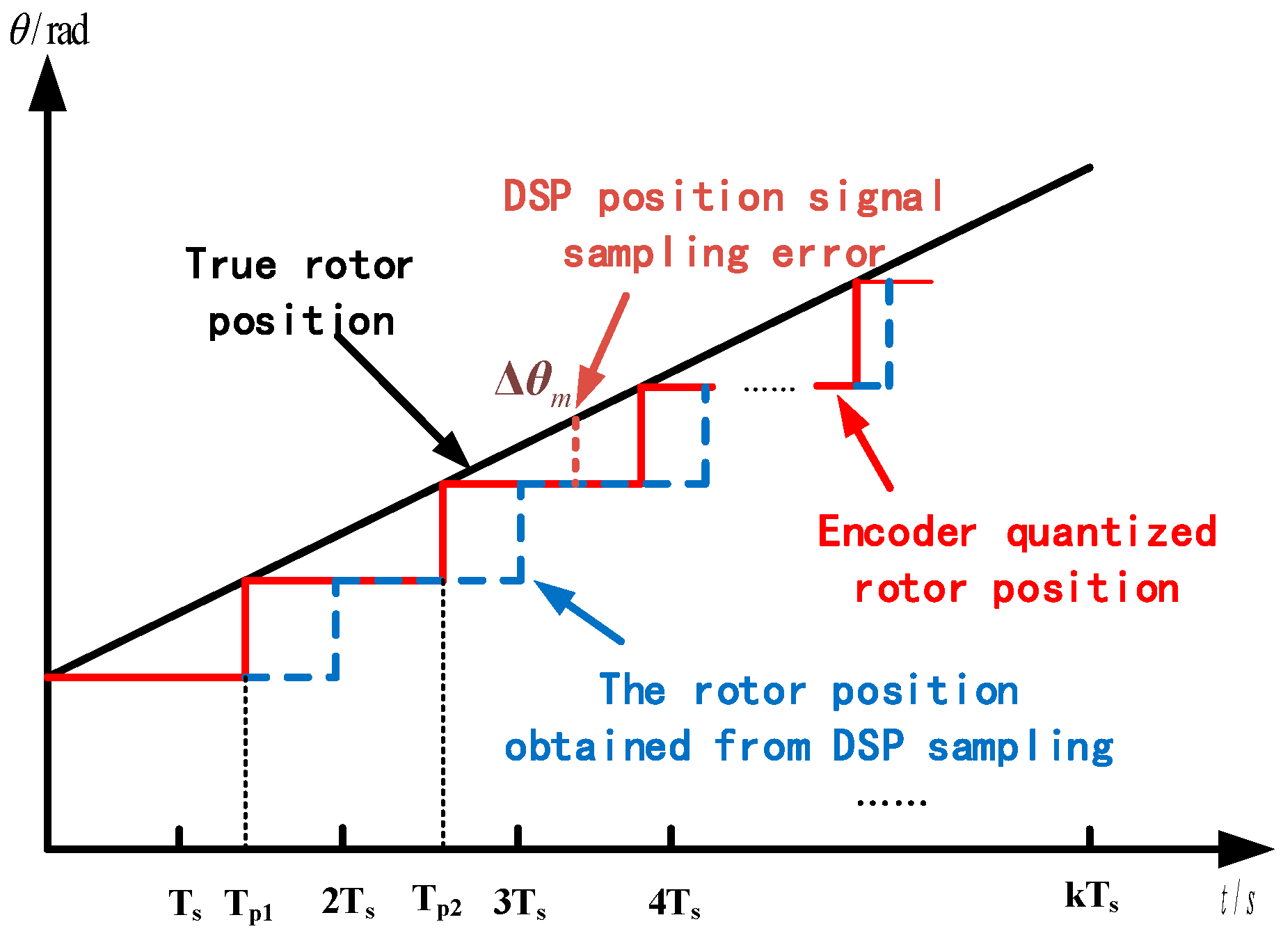
At the same time, in the actual digital control system, due to the time it takes for the chip to process data and the delay in obtaining the position signal by the DSP, this also aggravates the position signal acquisition error. The rotor position update map is shown in the
Figure 1.
If the rotor position tracking control (RPTC) is used,
in the figure is the sampling error of the DSP position signal. At this time, it is used as the feedback of the rotor position tracking control, which will inevitably affect the control performance. There is an error
in the feedback input. The transfer function of the RPTC controller is shown in Equation (3).
In the above equation, is any point on the position trajectory, which is a certain value; θ(s) is the actual position; R is the amplitude of the step command; Φ(s) is the closed-loop transfer function of the system.
Assume that the system output perfectly tracks the input to analyze the effect of position feedback errors.
The system input and output error is:
In the above equation, θ* is the given position trajectory.
The transfer function from input to output of RPTC control system is:
In the above equation, θ*(s) is the dynamic position setting, which is a variable; KT is the torque current constant; and λ is the filter time constant.
The magnitude of the control error caused by the position measurement error can be expressed as:
when →0 and →0 when →∞. Therefore, at low speed, the position feedback measurement error will seriously affect the position control performance of the system.
3. Traditional Interpolation Fitting Method and its Disadvantage Analysis
In order to solve the problem of motor position feedback acquisition at low speed and improve the accuracy of rotor position feedback, the traditional position signal compensation method is the interpolation fitting method.
3.1. Average Acceleration Interpolation
In this paper, the motor uses a resolver to measure the position. The 16-bit digital signal output is decoded using the AD2S80 decoding chip. Within the scope of one revolution of the motor, its output signal is divided into 65,536 parts. Even at low speeds, the position detection period Tp is still a small value. It can be assumed that the acceleration of the motor remains unchanged in one speed control cycle, and the motor speed in the next control cycle can be estimated from this acceleration, that is, the average acceleration method.
It is assumed that the two consecutive position signal update times of the motor are T
p1 and T
p2, respectively. The average acceleration of the motor in these two intervals can be calculated as
and
, so the average acceleration is
. According to the acceleration, the speed in the next interval can be estimated as:
At the same time, in order to make better use of the position sensor signal, before the output signal of the decoding chip is updated, the position interpolation value does not exceed the last position signal feedback value + 1. If the position signal value after interpolation exceeds this value, the position feedback signal is limited to the last position signal feedback value + 1 until the next decoding chip output signal is updated. When the motor reverses, the interpolated position signal will not exceed the previous position signal feedback value − 1 before the next decoding chip output signal is updated.
3.2. Polynomial Fit Interpolation
The average acceleration method regards the motor acceleration as a constant, so the motor position is considered as a quadratic function curve with respect to time. There is a certain gap between this and the actual motor position trajectory, and the error is relatively large in practical applications. In order to get closer to the actual position trajectory of the motor, the curve fitting method based on numerical analysis is introduced into the position signal interpolation algorithm. In order to minimize the complexity of the interpolation algorithm, reduce the unknown coefficients in the polynomial and ensure a more accurate simulation of the position trajectory, a cubic polynomial fitting method is selected for analysis.
The cubic spline interpolation function is defined: if (n + 1) nodes 𝑎 = 𝑥
0 < 𝑥
1 < ⋯ < 𝑥
n = 𝑏 are given in the interval [a, b]. At the same time there is a function
y =
f(
x) which has function values 𝑓(𝑥
0), 𝑓(𝑥
1), ⋯, 𝑓(𝑥
n) at these points. The function
satisfies that it is a cubic polynomial in each interval and is second-order derivable. Integrating the second derivative of
S(
x) twice in succession gives:
Mj and Mj+1 are the function values of the function S(x) at points xj and xj+1, respectively. hj is the width of the interval [xj, xj+1].
The first derivative of
S(
x) has the characteristic of being continuous on the small interval [𝑥
j, 𝑥
j+1], so the following relationship can be obtained by derivation:
According to the previous n nodes, (n − 1) equations in the form of Equation (8) can be written. By combining them with Equation (9), the value of the unknown Mj (j = 0, 1, ..., n − 1) in Equation (8) can be solved. Since two nodes cannot guarantee the accuracy of the algorithm and four nodes will greatly increase the complexity of the algorithm, it is not conducive to the realization of the algorithm. Therefore, this paper selects three nodes, that is, the signal of the position sensor is updated twice. When the position update is detected for the second time, the value of the interpolation function S(x) is calculated, and then the future rotor position of the motor is calculated according to the speed control period Ts.
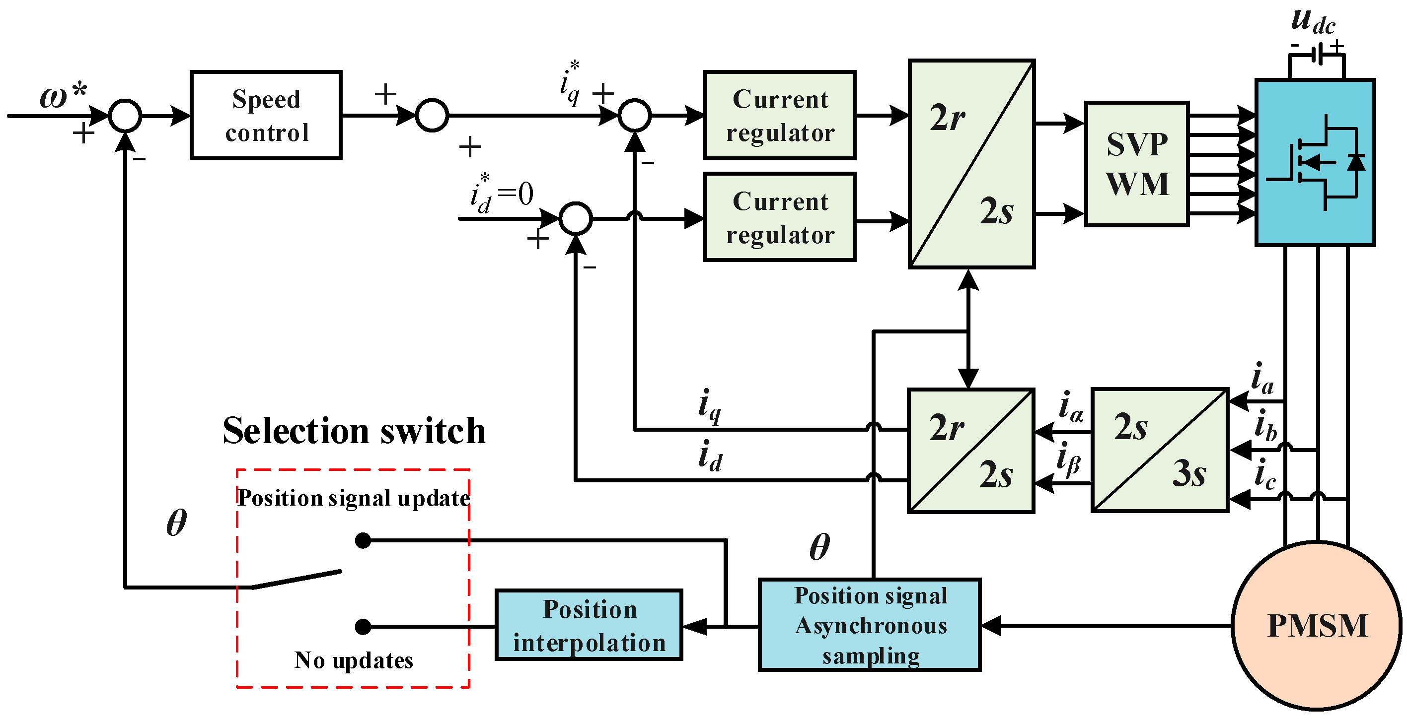
The control strategy block diagram of improving the position feedback accuracy using an interpolation algorithm is shown in
Figure 2.
3.3. Analysis of Disadvantages
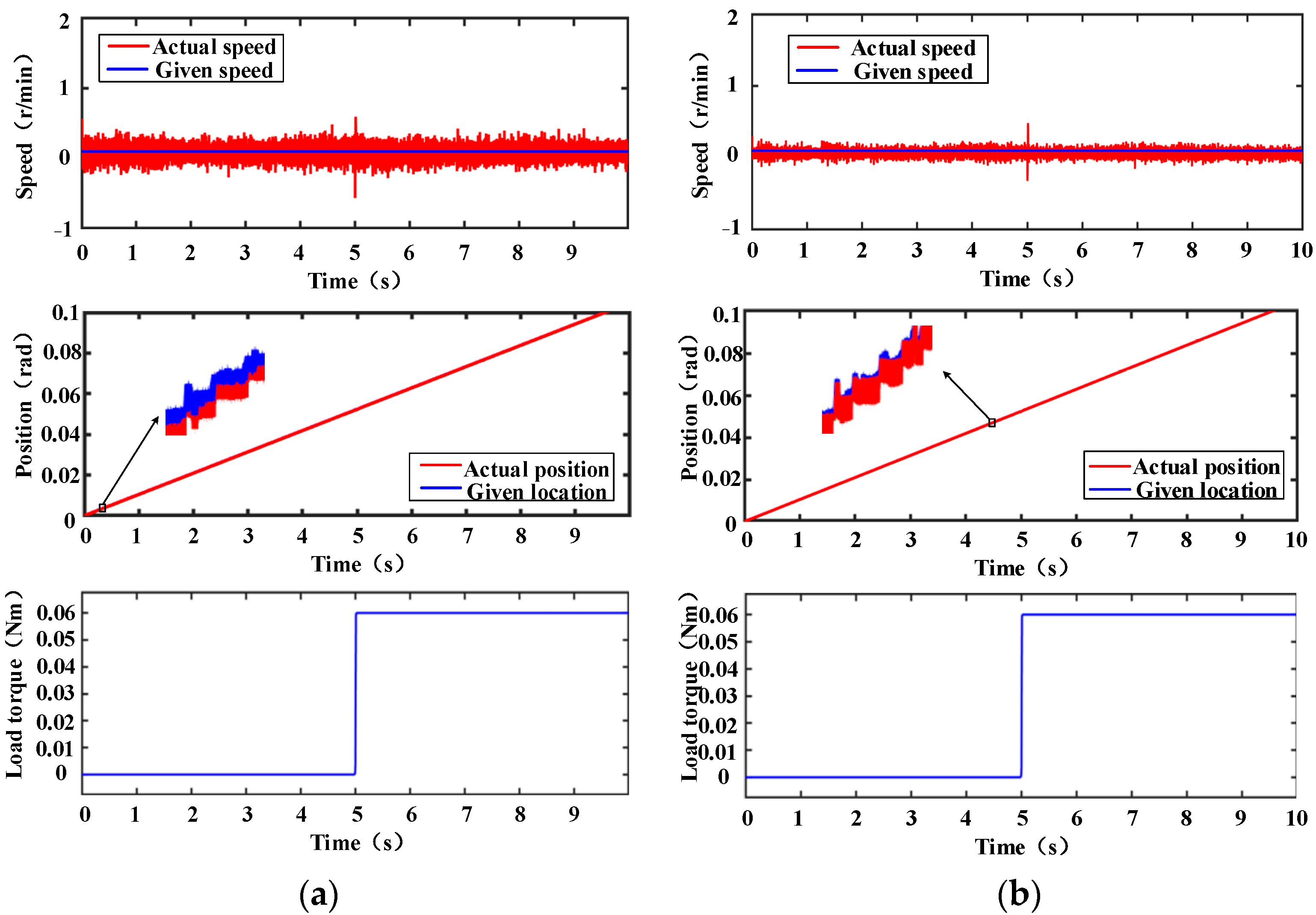
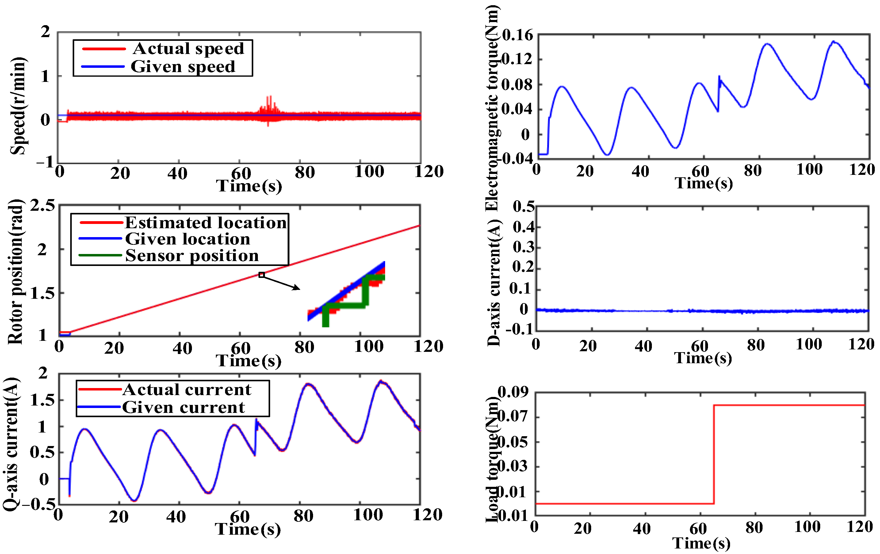
In order to illustrate the disadvantages of the traditional interpolation method, the corresponding simulation model is built in Simulink for analysis. The simulation parameters are shown in
Table 1. A position sensor module is built to simulate the stepped position signal collected when the actual DSP works. The simulation results are shown in
Figure 3.
It can be seen from
Figure 3b that the interpolation algorithm can play a certain role in compensating the position signal when the motor runs smoothly. However, when the speed is close to 0, the unstable control of the motor will lead to positive and negative fluctuations in the speed, as shown in
Figure 3d. At this time, the output signal of the sensor will fluctuate back and forth in a short period of time, which makes the interpolation algorithm based on the historical data of the position signal have a large estimation error, which seriously affects the accuracy of the position signal acquisition. This point can be clearly seen from the enlarged
Figure 3d; this position error will cause the motor speed fluctuation, which manifests as multiple small peak speed fluctuations in
Figure 3b,c.
The position signal compensation method based on the average acceleration method has problems in ultra-low speed operation, and the polynomial interpolation algorithm does not use the information of the motor itself, and the estimation results of the interpolation algorithm have certain lag and noise. At the same time, the interpolation algorithm cannot work in the first few speed control cycles of the motor starting, which will inevitably cause the starting current distortion of the motor and affect the starting performance. The observer method makes full use of the relevant information of the motor and uses the closed-loop control idea to ensure system stability and error convergence. The accuracy of the rotor position estimation results is greatly improved compared with the interpolation method. At the same time, the collaborative design of the feedforward compensation channel can also improve the antidisturbance performance of the system and improve the stability of the motor speed. In this paper, the observer is applied to the high-precision acquisition of the position signal of the permanent magnet direct drive servo motor at low speed, and it will be introduced in detail below.
4. Position Signal Acquisition Strategy Based on Position Observation
Many different observer design methods have emerged under the continuous learning and innovation of scholars at home and abroad. It is mainly divided into two categories: the state observer design based on the mechanical motion principle and the state observer design based on the back electromotive force principle. The former is mainly full-order/reduced-order state observers and extended state observers, and the latter is mainly extended Kalman filter and sliding mode observers. The full-order observer can observe the position of the motor as a feedback acquisition link for speed control. Additionally, it has better observation performance at low speed and can realize stable speed control, which is very suitable as the research object of this paper.
4.1. Position Signal Acquisition Strategy Based on Full-Order State Observer
First, a full-order observer is established for the motor system. The system state quantity
is selected, and the observer output quantity
y =
θ. In addition, the load torque
TL is counted as a part of the disturbance torque
Td. Write the mechanical motion equation of the motor in the form of the space state equation:
The mechanical equation of motion of the motor is:
In the above equation, J is the moment of inertia; Ba is the drag coefficient; Te is the electromagnetic torque; TL is the load torque.
Among them, the coefficient matrices
A,
B,
C and the control variable
u are, respectively:
Then the full-order observer is:
Among them,
and
represent the estimated value of the state quantity and the output quantity of the observer, respectively. K is the observer feedback gain matrix and
is defined. The error is defined as
. Then there are:
The characteristic equation corresponding to Equation (14) is:
It can be seen from Equation (15) that the poles of the characteristic equation are configured by setting different parameters
k1,
k2,
k3 to meet the error convergence speed required by the system. In this paper, the poles of the characteristic equation are configured in the form of multiple roots, and the poles are set at −
ω0, which can ensure the stability of the observer and the convergence of the error. The observer gain matrix can be approximated as:
where
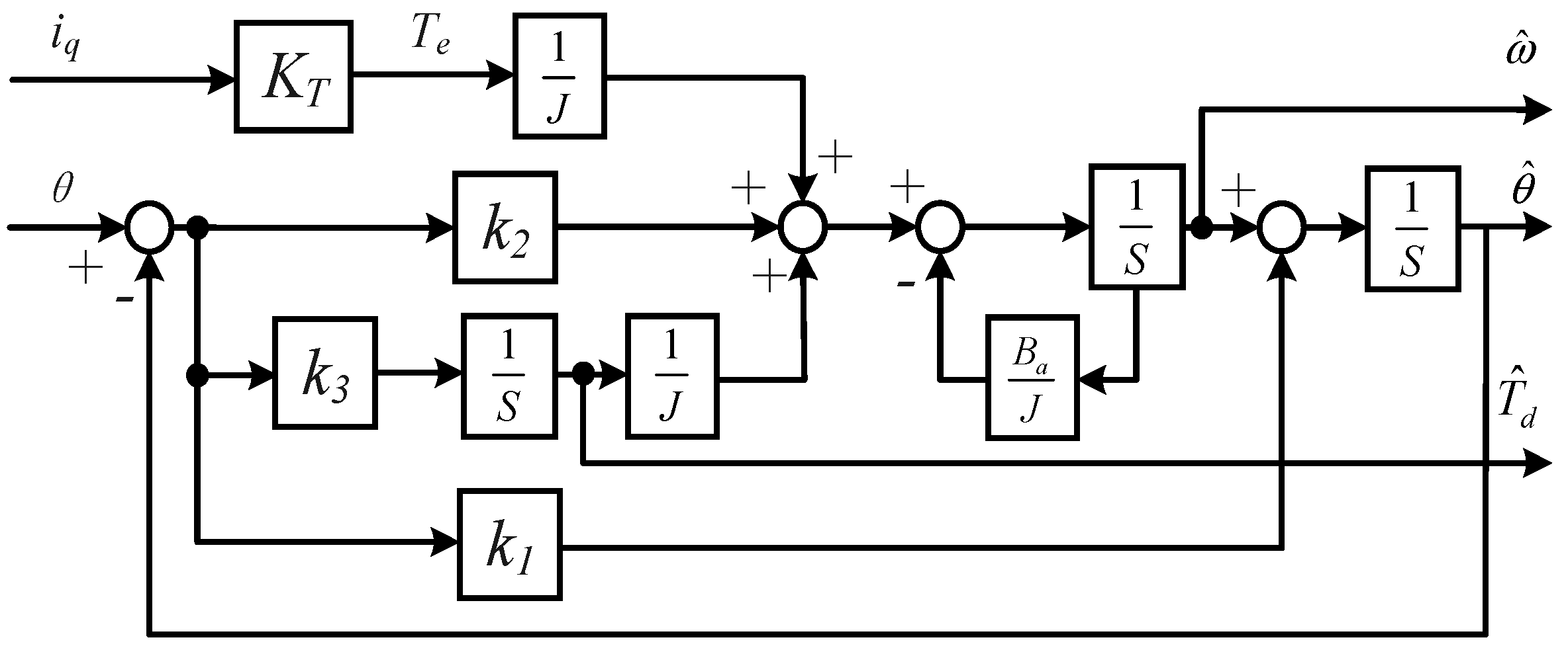
ω0 is the observer bandwidth. The full-order state observer structure designed according to Equation (12) can be represented by
Figure 4:
The full-order observer makes full use of various state information of the motor and realizes high-precision tracking of the position signal through error closed-loop feedback. Compared with the interpolation method that cannot obtain the system disturbance information, the full-order observer can estimate and use the system disturbance information Td, which significantly improves the observation accuracy of the position signal. Further considering the form of disturbance, the full-order observer can theoretically realize static-difference-free observation of fixed disturbances. However, in practical applications, disturbances often appear in more complex forms, such as step, sinusoidal and so on. This requires the observer to have a certain ability to track time-varying disturbances, that is, better dynamic performance. The direct method is to expand the state quantity of the motor system.
4.2. Position Signal Acquisition Strategy Based on Extended State Observer
The derivative of the external disturbance
is introduced as a new state quantity, thus forming an extended state observer. At this time, the new system state variable
and output y = ω. The system state equation is updated as:
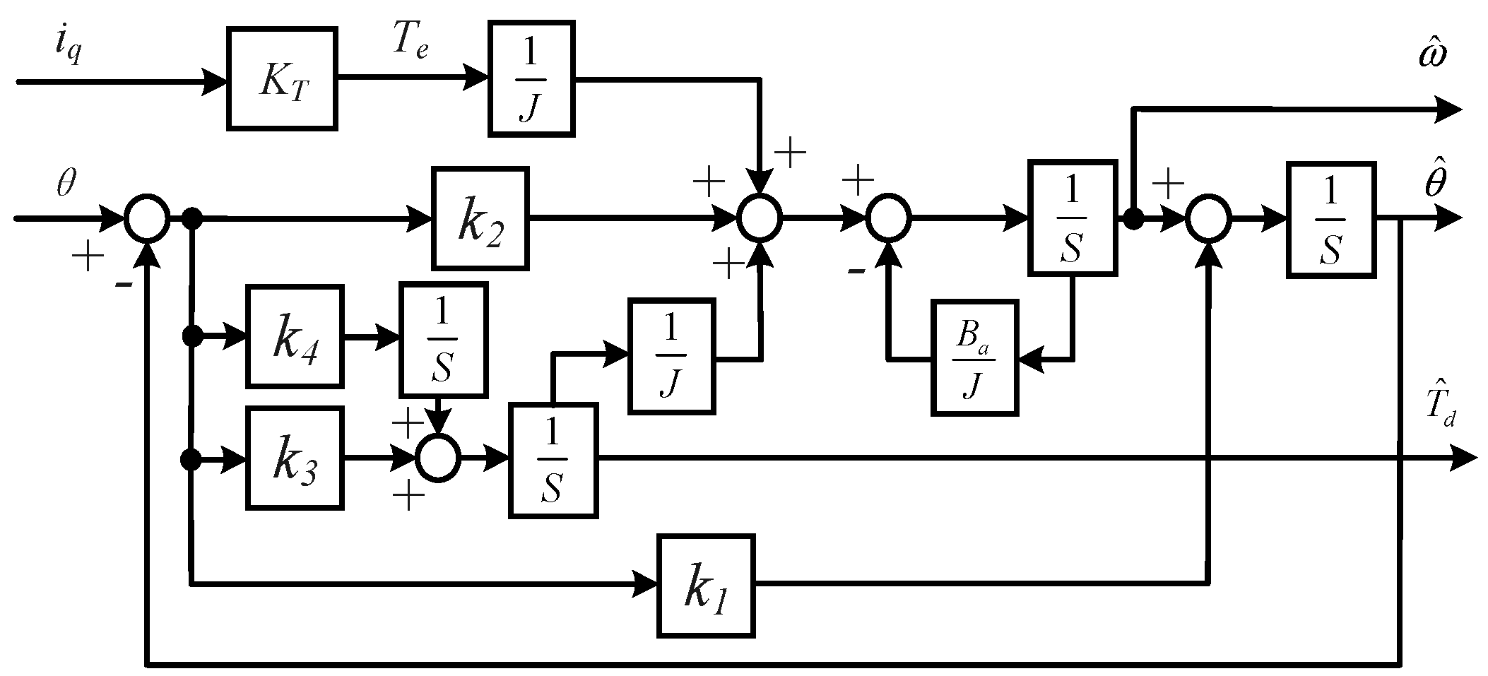
Further lead to the fourth-order extended state observer:
Draw the extended state observer structure as shown in
Figure 5:
Similarly, by solving the characteristic equation of the observer state error and configuring appropriate poles, the tracking performance of the observer to the position signal is met. The poles of the characteristic equation are configured in the form of multiple roots, and the poles are set at −
ω0. The observer gain matrix can be approximated as:
The fourth-order extended state observer introduces the disturbance derivative into the state quantity, realizes the static error-free tracking of the slope disturbance and can effectively improve the dynamic performance of the observer. Similarly, the second derivative of the disturbance can be further introduced as a new state quantity. In this way, a fifth-order extended state observer is realized to improve the tracking performance of the observer for complex disturbances. However, as the order of the observer increases, its sensitivity to high-frequency noise gradually increases. Therefore, in practical applications, it is necessary to select the order of the observer reasonably according to the system uncertainty and speed control requirements.
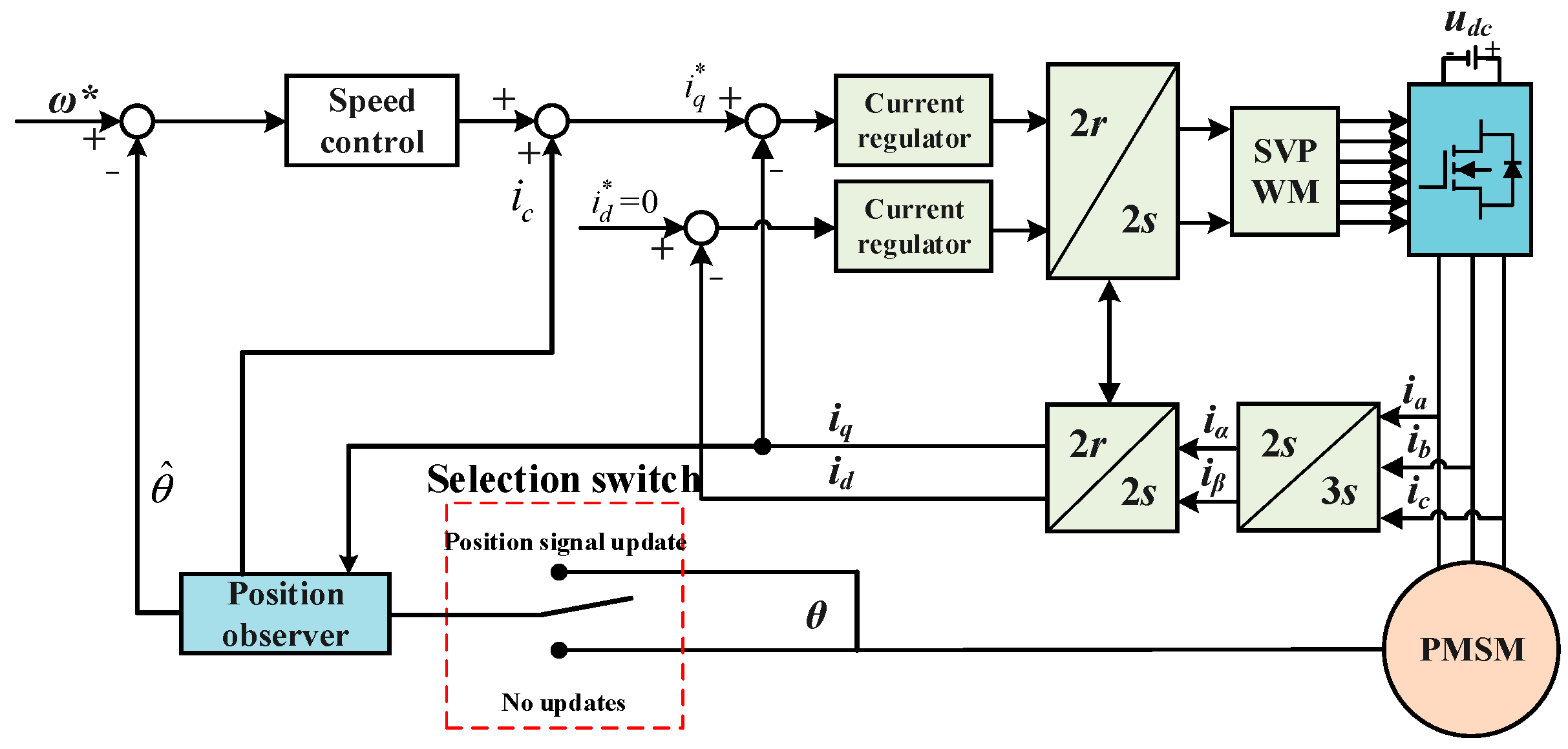
The block diagram of position acquisition and speed control strategy based on observer compensation is shown in
Figure 6:


