1. Introduction
The improvement of efficiency in electric motors is crucial and highly advantageous, considering their substantial contribution to global electricity consumption [
1]. In this regard, researchers have suggested the utilization of permanent magnet (PM) motors to enhance efficiency by minimizing core losses. PM machines offer the advantage of increased power-to-volume ratio [
2]. Furthermore, permanent magnet synchronous motors (PMSMs) find extensive use in various industrial applications due to their high torque density and efficiency [
3]. Unlike brushless DC (BLDC) machines, which exhibit trapezoidal EMF voltage, PMSMs generate sinusoidal EMF voltage [
4,
5]. Additionally, sinusoidal-type PMSMs exhibit lower torque ripple compared to their trapezoidal-type counterparts [
6].
The incorporation of rare-earth materials such as dysprosium (Dy) in permanent magnets (PMs) is common to achieve high-performance characteristics. However, the cost of rare-earth materials is significantly expensive [
7]. Additionally, these materials are vulnerable to demagnetization when exposed to high temperatures and flux-weakening control in the machine [
8,
9]. Consequently, researchers have conducted numerous studies aiming to maximize the output power per unit magnet volume [
10]. One prevalent approach involves the modification of rotor structures [
11,
12,
13]. Examples of such modifications include the utilization of a ferrite magnet-based interior PMSM [
12] and of hybrid excitation motors [
13]. These innovations demonstrate remarkable improvements in output power per unit magnet volume.
Direct-drive permanent magnet machines (DD-PMMs) have gained attention for their high output power per magnet volume, torque density, and efficiency in applications such as wind power generation, hybrid electric vehicles (HEV), and ship propulsion [
14,
15]. However, DDPMMs have the drawbacks of weight and volume. To address this, researchers have focused on dual air-gap (DAG) PMSMs, known for their reliability, low noise, and gearless structure [
16,
17]. These machines typically employ fewer stator winding poles than rotor magnet poles to achieve high torque density at low speeds, leveraging the magnetic gearing effect [
18]. While conventional DAG-PMSMs have low torque ripple [
19], recent research has focused on modified DAG-PMSMs to further reduce torque ripple [
20]. As a result, DAG-PMSMs have emerged as a promising alternative for direct-drive applications [
21]. These machines exhibit a double electromotive force (EMF) voltage compared to conventional permanent magnet synchronous machines due to their flux modulation effect. Consequently, DAG-PMSMs are capable of generating high torque density [
22].
In general, researchers aim to reduce magnet volume and increase the amplitude of air-gap flux density [
23]. To achieve these goals, Halbach-array magnets placed in the slot opening have been introduced in DAG-PMSMs, resulting in a 43% improvement in torque density compared to conventional single air-gap PMSMs [
24,
25]. Other topologies for DAG-PMSMs have also been proposed to achieve high torque density compared to single air-gap machines [
26,
27,
28]. In recent years, yokeless DAG-PMSMs have been developed to increase torque per magnet volume and reduce costs [
27]. While the yokeless DAG-PMSM structure achieves improvements in torque density and torque ripple reduction, there has not been a substantial reduction in torque per magnet volume. It should be noted that the rotor iron in DAG-PMSMs is more prone to saturation compared to single air-gap machines due to the insertion of magnets in both the inner and outer rotor surfaces. This saturation leads to distortions in the flux distribution and results in heat generation within the rotor core [
28].
In this paper, we propose a DAG-SPMSM. The construction of the motor was previously explained in the authors’ earlier work [
29]. This radial-type motor features two stator cores and one rotor core in the middle. At the center of the rotor, a magnetic screen is positioned with the primary purpose of completely isolating the outer and inner motors, as previously elucidated in [
29]. However, the design of the magnetic screen was not discussed in the previous study, as its size was chosen arbitrarily based on the flux density distribution in the rotor. Consequently, this paper aims to explore the effect of the magnetic screen’s height/thickness on the electromagnetic characteristics of the motor. To validate the effectiveness of the proposed design, a prototype was manufactured and subjected to testing. The result demonstrates that the motor passed the qualification test with an efficiency of 95.2%.
This paper is organized as follows. First, the motor’s structure, which has been explained in [
29], is summarized in
Section 2 for the readers’ convenience.
Section 3 presents the simulation results obtained by varying the magnetic screen size as a percentage of the overall rotor thickness. Subsequently, in
Section 4, the experimental results are presented to verify the effectiveness of the design. Finally, the conclusion is provided in
Section 5.
2. Structure of Proposed Motor
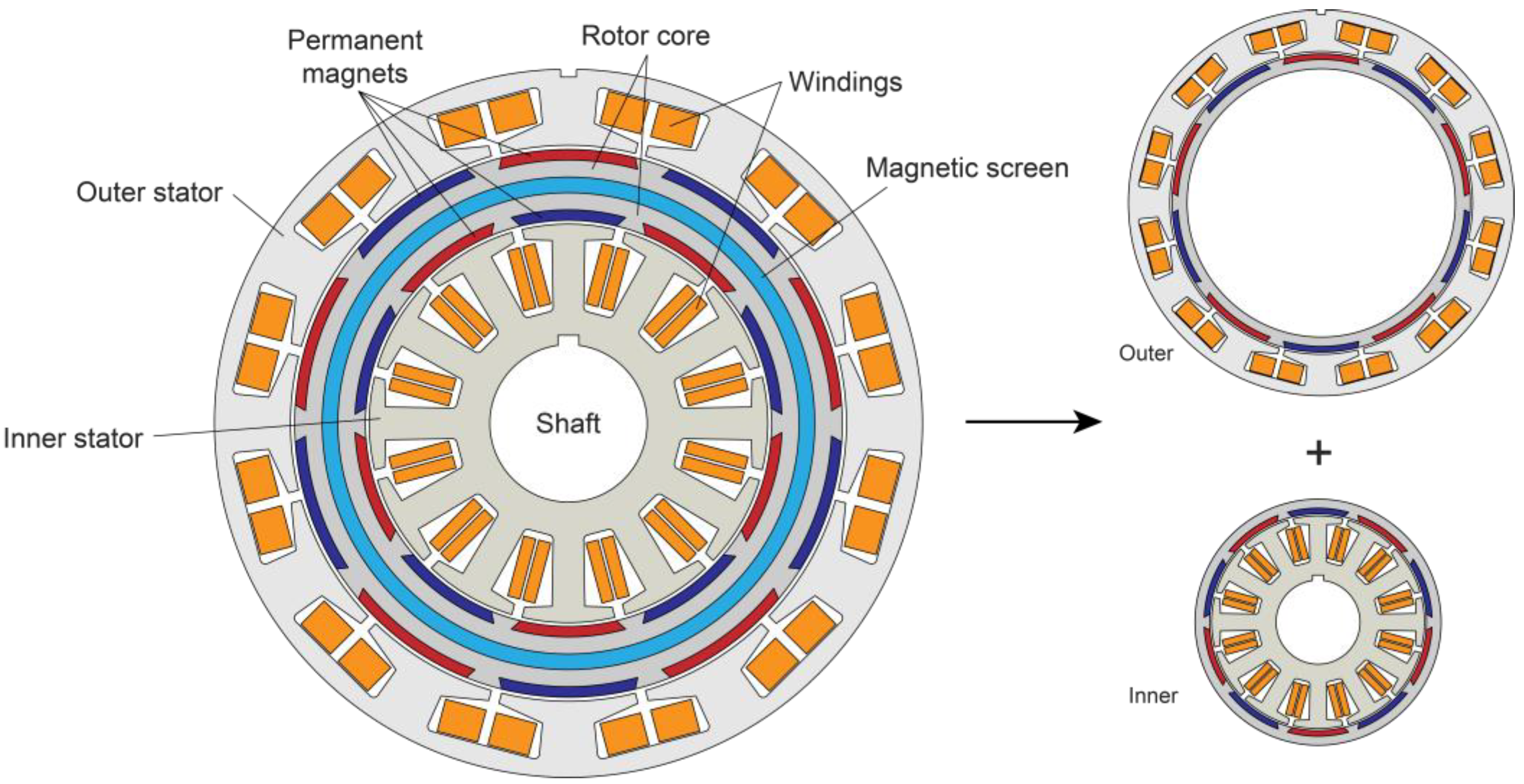
The structure of the proposed motor is depicted in
Figure 1. The windings for the outer and inner motors are connected in series for each corresponding phase. The PM arrangement has been explained in [
29], with the red and blue colors indicating north and south polarity, respectively. As shown in the figure, the proposed design allows the motor to be effectively separated into two distinct parts, namely the outer and inner motors. This separation is facilitated by the placement of the magnetic screen in the middle of the rotor and the PM arrangement, as previously described in [
29]. As a result, there is no mutual flux between the outer and inner motors, and the flux becomes localized with a much shorter path.
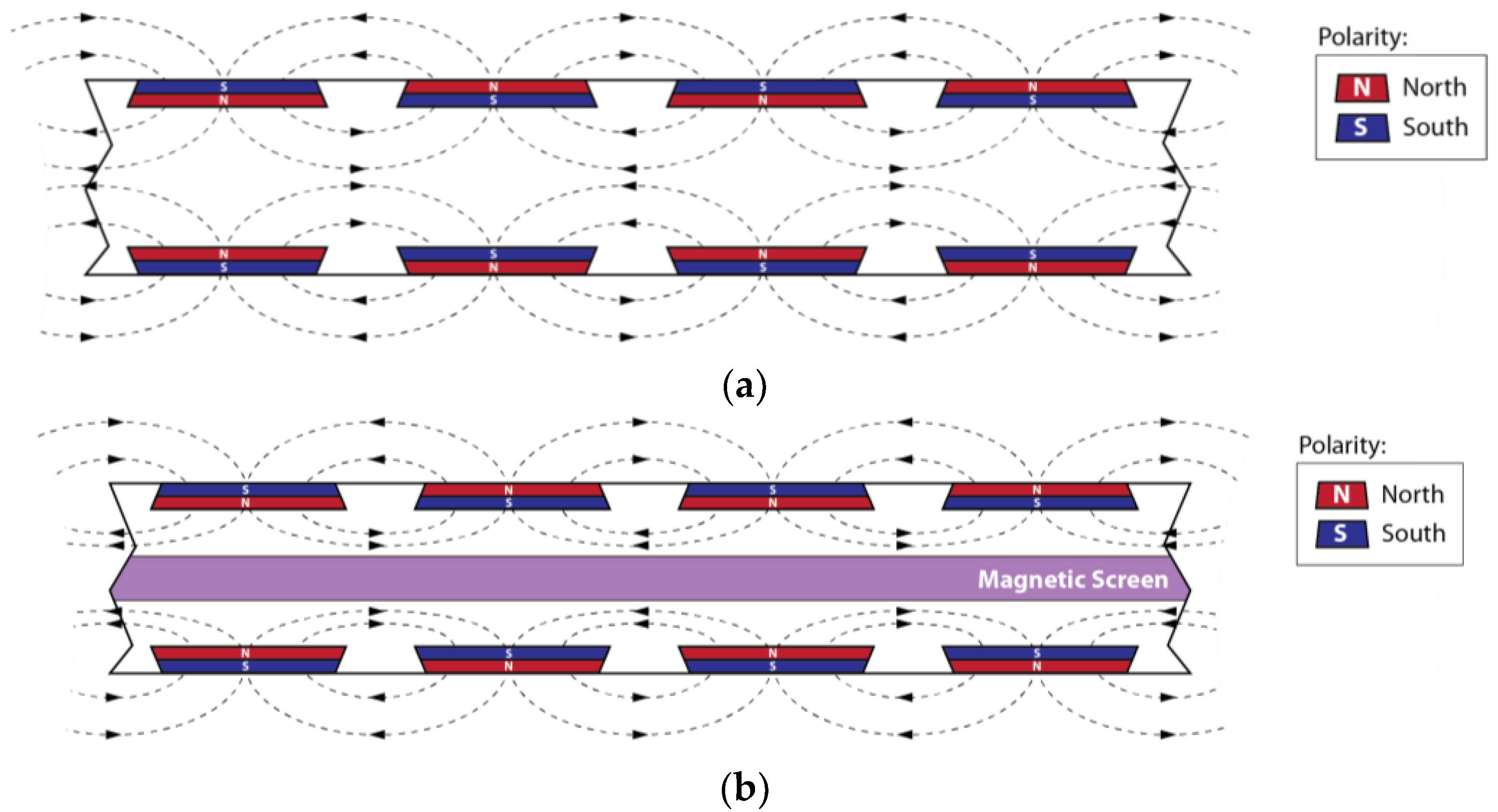
The importance of using a magnetic screen is depicted in
Figure 2. The zig-zag arrangement of the PMs results in a short, localized flux path, minimizing interaction between the outer and inner motors. However, it is evident that the fluxes meet at the center and flow in the same direction. Therefore, the presence of a magnetic screen becomes essential to achieve better isolation between the two sides.
The material used for the magnetic screen should be nonconductive or, at the very least, significantly less conductive than the rotor core material. In this case, stainless steel SUS304 is selected as the material for the magnetic screen. This choice is based on its poor conductivity compared to the rotor material, which is the ferromagnetic 27PN1500.
The motor dimensions are provided in
Table 1. Originally designed as a traction motor for a boat propeller, the value of the magnetic screen is derived from the previous results in [
29] and serves as a baseline for subsequent analysis. The motor uses 27PNF1500 for the stator and core material and NdFe35 for the magnets. It operates as a three-phase motor, with both the external and internal motors having three-phase windings. The phases of each motor are connected in series, meaning that Phase A of the external motor is connected in series with Phase A of the internal motor, and so on.
It is important to note that the proposed motor does not fall into the high-power category, which makes achieving high efficiency challenging. In the previous study, the experimental results demonstrated an efficiency of 93.57%. However, for propeller applications, a higher efficiency of around 95% is expected to ensure optimal performance and energy utilization. As such, further efforts are focused on optimizing the motor design and magnetic screen characteristics to achieve the desired efficiency level for propeller propulsion.
3. Simulation Results
In this section, finite element analysis (FEA) is utilized to investigate the effect of the magnetic screen on the electromagnetic characteristics of the proposed motor. Based on the data provided in
Table 1, the thickness/length of the rotor core can be calculated by subtracting the outer diameter from the inner diameter, resulting in a value of 26 mm. Moreover, as depicted in
Figure 2, the PM is buried within the rotor in the form of a slot, with a thickness of 2 mm, as indicated in
Table 1. The remaining area is available for accommodating the magnetic screen. As shown in
Figure 1, the magnetic screen is positioned precisely in the middle of the rotor core.
The key question that arises is how much of the rotor core portion should be allocated to the magnetic screen. To address this, the screen thickness is expressed as a percentage of the overall rotor length, which is 26 mm. To represent this variable, we use , denoting the screen height length. By varying the value of and observing its impact on the electromagnetic characteristics through FEA, we can optimize the design of the magnetic screen for enhanced motor performance and efficiency.
The screen height is systematically varied from 10% to 40% of the overall rotor length, with an incremental step of 2%. Based on this calculation, the base value of the screen height, which is 3 mm, corresponds to a percentage of 11.5% with respect to the total rotor length. This adjustment process starts from the middle of the rotor core, and the expansion is evenly distributed to both the internal and external sides. For instance, if the magnetic screen thickness is increased to 4 mm, this represents an additional 0.5 mm thickness added equally to both the inner and outer sides from the original 3 mm thickness.
As explained in [
29], the addition of the magnetic screen results in a reduction in torque.
Figure 3 illustrates the static torque reduction for different values of
, ranging from 10% to 40%. Here, the term “static” refers to the simplified 2D simulation, where a three-phase sinusoidal current is injected into the phase windings. The RMS current for each phase is constant at 10A, based on the value provided in [
29].
When is set to 10%, the average torque is measured at 8.36 Nm. However, as increases to 40%, the average torque is significantly reduced to only 6.46 Nm, representing a decrease of approximately 22.7%.
To further analyze the effects of varying
on motor performance, it is essential to consider the torque ripple. The torque ripple can be calculated using the following formula:
As observed in
Figure 3, the torque ripple exhibits an increasing trend as the magnetic screen size becomes thicker. The smallest torque ripple is attained when the screen size is 10%, measuring at 6.96%. Conversely, the highest torque ripple is recorded when the screen size is 40%, reaching 10.44%.
Similar phenomena can also be observed regarding the back-electromotive force (back-EMF). As the thickness of the screen increases, there is a corresponding reduction in the back-EMF, as illustrated in
Figure 4.
For clarity,
Figure 5 provides the average torque value and torque ripple for each magnetic screen size. The results illustrate that the torque smoothly decreases as the magnetic screen size increases. However, the behavior is different for torque ripple. When the screen size is small, the torque ripple appears to be relatively unaffected. However, as the screen height reaches 26%, the torque ripple starts to increase notably.
The reduction in torque and back-EMF can be explained by observing the flux distribution as depicted in
Figure 6 below. As the screen height increases, the rotor core area decreases. This disrupts the flow of flux in the air gap, thereby affecting the torque. As shown in the figure, the flux density actually decreases as the screen height increases. Indirectly, it also impacts the torque ripple, although not in a linear manner as with torque. The influence of changing the structure on torque ripple is extensively explained in [
30]. This phenomenon is related to the harmonics of air-gap flux. Depending on the motor’s structure, the harmonics that affect torque ripple differ, and further analysis of this matter is beyond the scope of this paper.
In
Figure 5, a circle mark on the graph designates the selected point for the screen height, which is at 22%. This specific choice corresponds to a screen height of 5.7 mm, and it appears to be the optimal point, balancing torque reduction and torque ripple. This indicates that, for this particular motor design, a screen height of 22% achieves the best compromise between reducing the torque and maintaining a tolerable level of torque ripple. Selecting an appropriate screen height is crucial to achieve the desired motor performance, taking into account the trade-offs between torque reduction and torque ripple.
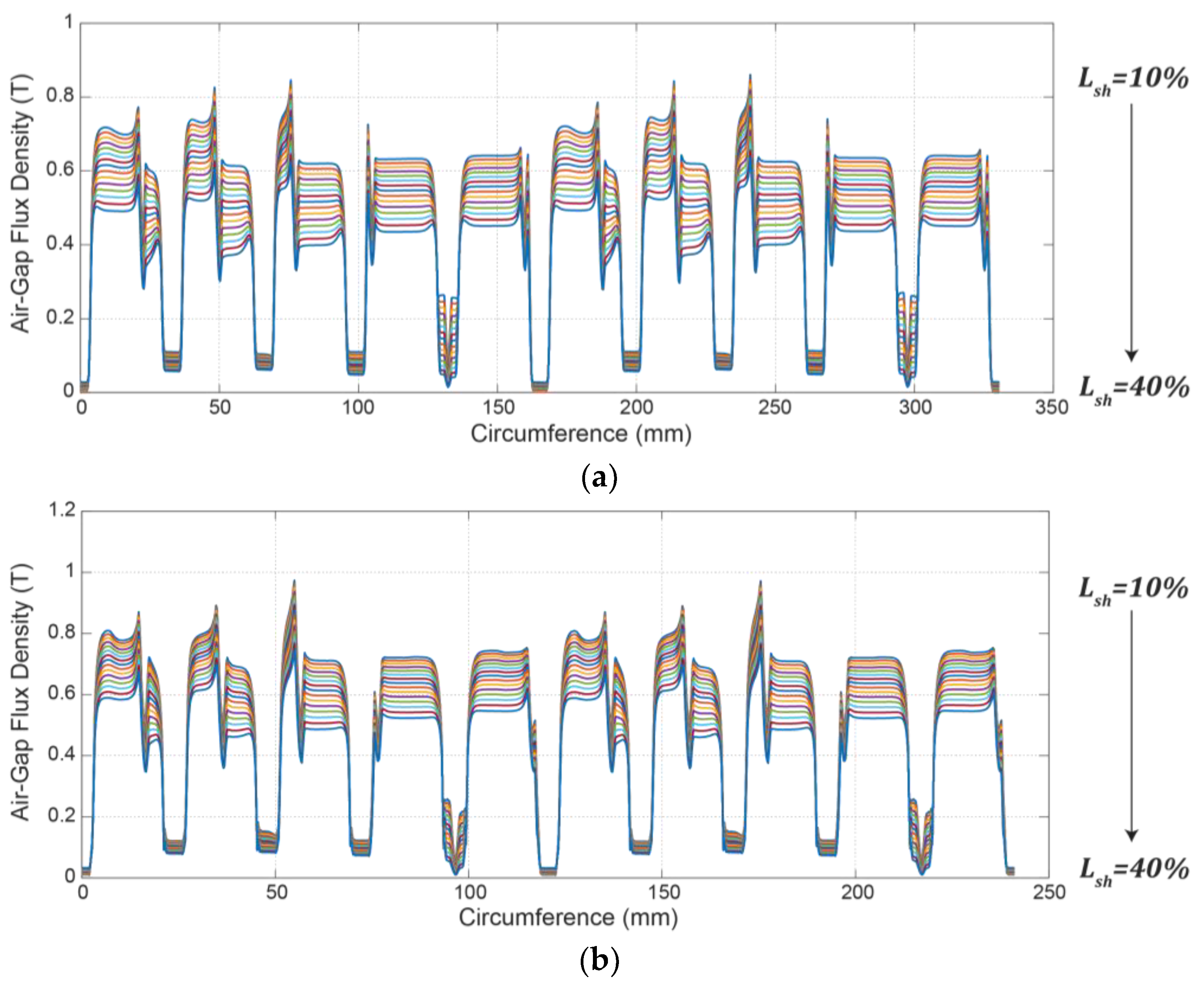
As is well known, energy conversion in the motor occurs in the air gap, and the distribution of flux across the air gap significantly influences torque generation.
Figure 7 provides an insight of how the flux is distributed along the air gap. The x-axis denotes the circumference of the outer and inner diameter for
Figure 7a,b, respectively.
It is evident from the figures that, in general, the flux density in the outer air gap is lower than that in the inner air gap. This disparity is primarily due to the overall larger area on the outer perimeter of the rotor. However, the overall shape of the flux distribution is similar for both air gaps. Additionally, the analysis reveals that the average air-gap flux density decreases with increasing screen length. For the outer air gap, the shortest screen length generates the highest flux density at an average of 0.52 T, while the longest screen length generates the lowest at only 0.35 T. Similarly, for the inner air gap, the shortest screen length results in the highest average flux density at 0.56 T, while the longest screen length generates the lowest at 0.39 T. These findings emphasize the significant impact of the magnetic screen length on air-gap flux distribution, which, in turn, influences the torque generation and motor performance.
The presence of the magnetic screen indeed leads to a reduction in both the average and peak values of air-gap flux density. As a result, it can be suspected that the motor’s torque output is affected and more current is required to produce the same torque as that with no magnetic screen. This suspicion is validated by comparing the static torque, as depicted in
Figure 8.
According to the information presented in
Table 1, the initial output torque of the motor is 7.75 Nm. When the motor operates without a magnetic screen, it requires 9 Arms of current to generate the necessary torque. However, when the magnetic screen is implemented, the torque output is reduced and, as a result, an increased current of 10 Arms is necessary to maintain the torque output at 7.75 Nm.
Figure 9 presents a comparison of the air-gap flux density in the proposed motor. As observed in
Figure 5, it was speculated that increasing the magnetic screen height reduces the air-gap flux, subsequently leading to a reduction in torque. While this concept holds true in general, it is interesting to note that, when comparing the base model (without the magnetic screen) with 9 Arms of current to the proposed model with the selected magnetic screen height and 10 Arms of current, the air-gap flux density in the proposed model is still lower than that in the base model. This observation remains consistent for both the outer and inner motors. Surprisingly, as shown in
Figure 8, it was confirmed that the torque output is the same for both the base model and the proposed model with the selected magnetic screen height and increased current. This raises questions about the actual effect of the magnetic screen on torque.
Indeed, the direction of flux in the air gap can be categorized into two main components: radial and tangential. The radial flux is often associated with undesirable effects such as vibration and noise, making it less desirable in motor designs. On the other hand, the tangential flux is the component responsible for generating torque in the motor. This means that even if two motors have the same air-gap flux density, the one with a higher quantity of tangential flux will produce a higher torque output. The tangential flux is the crucial factor in determining the motor’s torque-generating capability, and optimizing it is essential for achieving the desired motor performance. Therefore, in the context of the magnetic screen’s impact on torque, it becomes vital to examine how the screen affects the distribution of tangential and radial flux in the air gap.
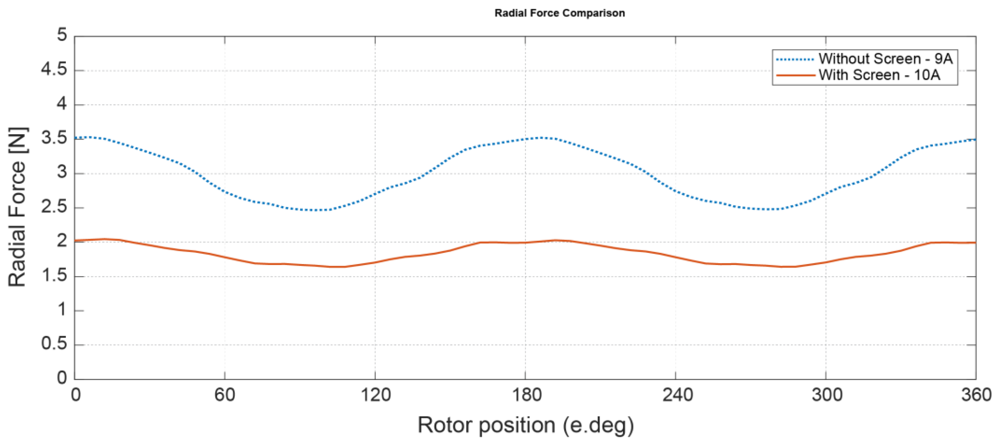
According to the limitations of the FEA tool utilized by the authors, measuring the radial flux is easier than measuring the tangential flux. Consequently, the radial force can be used as an indirect indicator to assess whether the magnetic screen affects the tangential flux in the motor. The results are illustrated in
Figure 10.
As anticipated, the radial force of the proposed model with the magnetic screen is lower compared to the base model, even with the higher current. The average and peak radial forces for the base model are 3.0 N and 3.53 N, respectively, while the average and peak radial forces for the proposed model are 1.84 N and 2.04 N, respectively.
Based on these findings, it can be concluded that the presence of the magnetic screen leads to a significant reduction in the radial force compared to the base model. This reduction in radial force implies that more tangential flux is produced when the magnetic screen is implemented with higher current. Therefore, the magnetic screen’s effect on the motor design can be indirectly verified by observing the changes in the radial force, providing valuable insights into its impact on the tangential flux distribution and ultimately the motor’s torque output.
Finally, the comparison of back-EMF characteristics is presented in
Figure 11. The dotted lines represent the base model without the magnetic screen, while the solid lines represent the proposed model with the magnetic screen. From the graph in
Figure 11a, it is evident that the back-EMF waveform of the proposed model is much closer to a sinusoidal shape compared to that of the base model.
To further quantify the improvement in waveform quality, a Total Harmonic Distortion (THD) analysis is performed on the back-EMF waveforms. The results are displayed in
Figure 11b as well. It is apparent that the proposed model exhibits significantly lower third harmonic content compared to the base model, with a remarkable reduction of 67%.
The improvement in the back-EMF waveform, with reduced harmonic distortion and closer resemblance to a sinusoidal shape, is a positive indication of the benefits of the magnetic screen in the motor design. This improvement has implications for smoother operation, reduced noise, and potentially improved efficiency of the motor.
Table 2 provides a breakdown of the weight distribution among some motor components, as determined through the 2D simulation. The components considered for weight calculation are cores, magnets, magnetic shielding, and windings, with their combined weight totaling 5.84 kg. Notably, the outer stator emerges as the heaviest component, closely trailed by the windings. The outer stator winding alone constitutes approximately 64% of the total winding weight. Simultaneously, the outer stator core comprises roughly 60% of the total stator core weight. In contrast, the rotor exhibits a somewhat more balanced weight distribution. Specifically, the outer rotor core accounts for around 53% of the total rotor core weight, and the outer PMs contribute approximately 56% of the overall PM weight.
4. Experiment Results
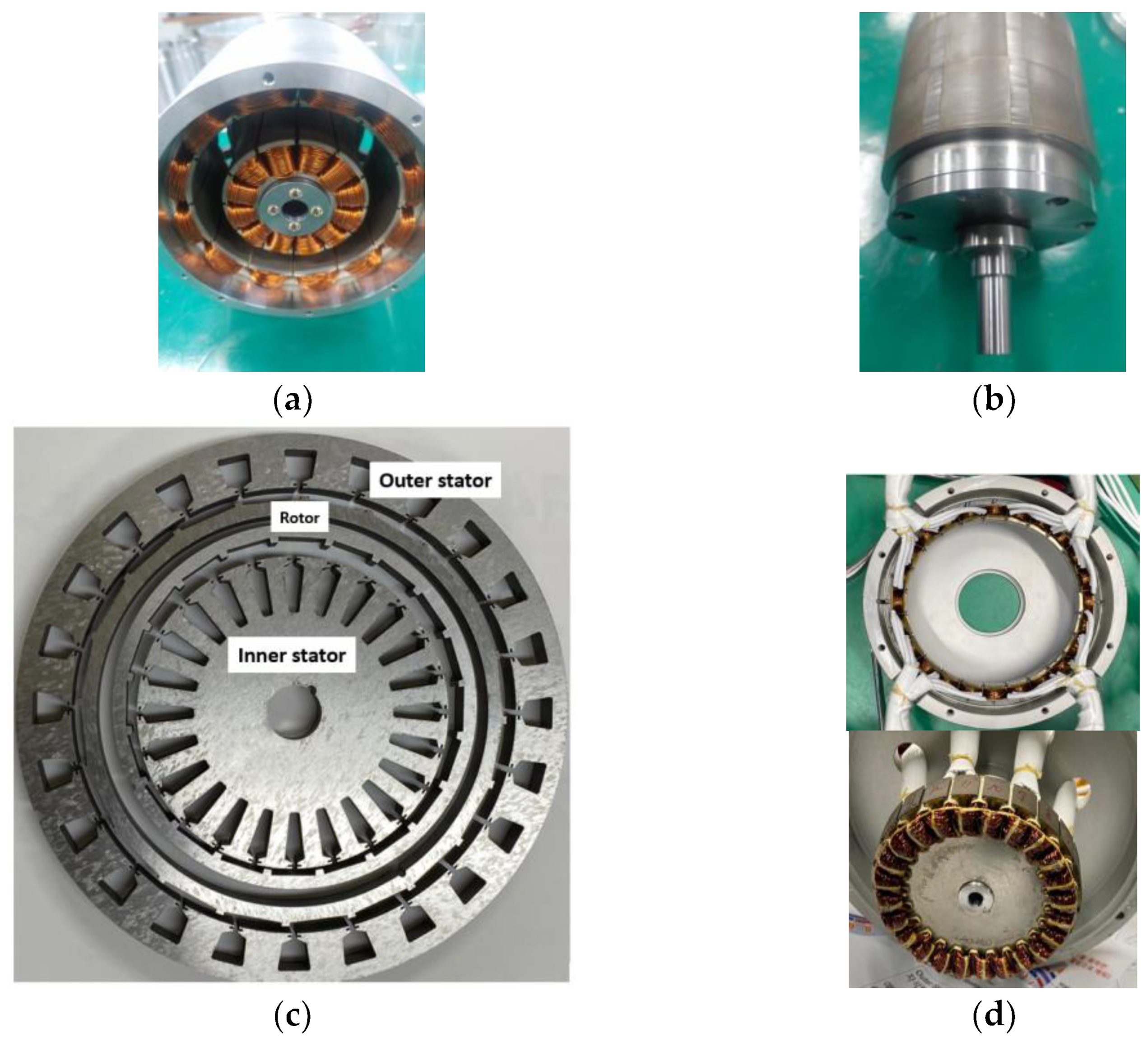
To validate the proposed design, a physical prototype was manufactured, as depicted in
Figure 12.
Figure 12a shows the stator and winding of the motor, with a hollow area where the rotor will be inserted. In
Figure 12b, the rotor of the motor is displayed.
Figure 12c shows the rotor and stator cores. There are four distinct core parts: the inner and outer stator, as well as the outer and inner rotor cores. The space between the outer and inner rotor cores is designated to accommodate the magnetic screen.
Figure 12d shows the assembly of windings within the housing. The upper picture corresponds to the outer stator, while the lower image pertains to the inner stator.
Figure 12e depicts the insertion process of the rotor into the stator. Lastly,
Figure 12f shows the final assembly of the motor. The windings are all pulled to the rear for easy connection to the controller.
Figure 13 provides an overview of the motor assembly. The cores are securely affixed to the frame through the use of bolts. Bearings are strategically positioned at both the front and back of the motor, with the rotating shaft situated exclusively at the front. This configuration, while structurally straightforward, does present the potential challenge of rotor balancing if the precise alignment of the rotor or bearings is not achieved.
Figure 14a shows the experimental setup for the motor test bed, with the motor connected to a load and a torque sensor (CSA-5KM-SP from CASKOREA, Gyeonggi-do, Republic of Korea) capable of measuring up to 5 kgf∙m or 49 Nm. Worth noting, the “SP” designation in the model name signifies the incorporation of an internally attached speed sensor.
Figure 14b shows the use of a single power analyzer (WT1600 from Yokogawa) to measure the motor’s output power.
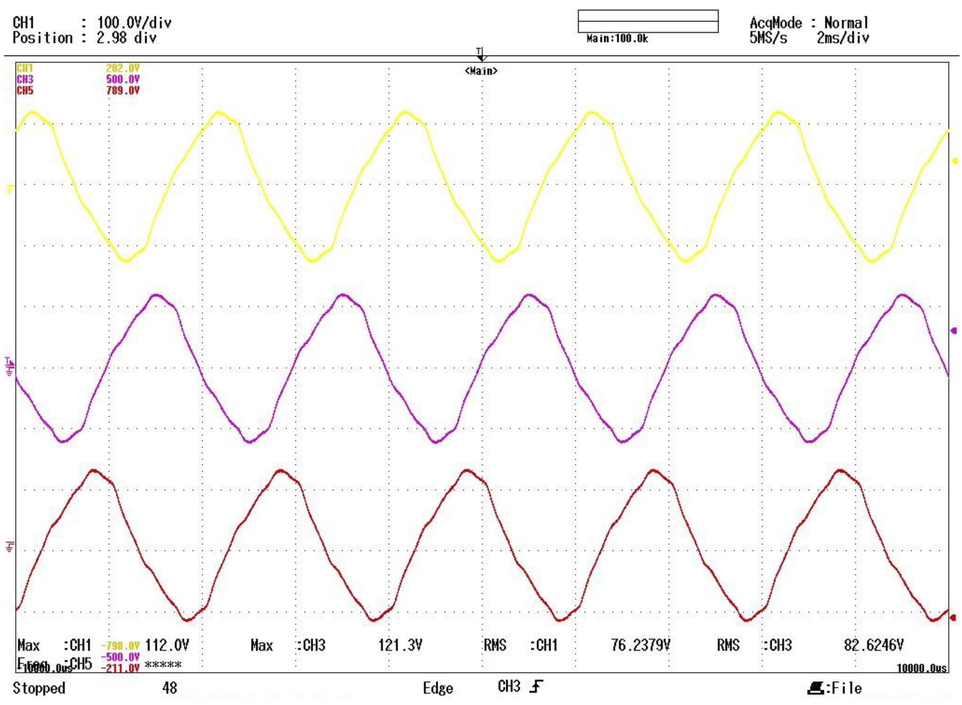
Prior to sending the motor for formal testing, we conducted a basic evaluation of the motor’s back-EMF in our own laboratory. In this assessment, the motor was rotated using a servo motor in a generator mode, and the results are displayed in
Figure 15. Notably, the waveforms for all three phases exhibit remarkable similarity, featuring closely matched maximum and RMS values.
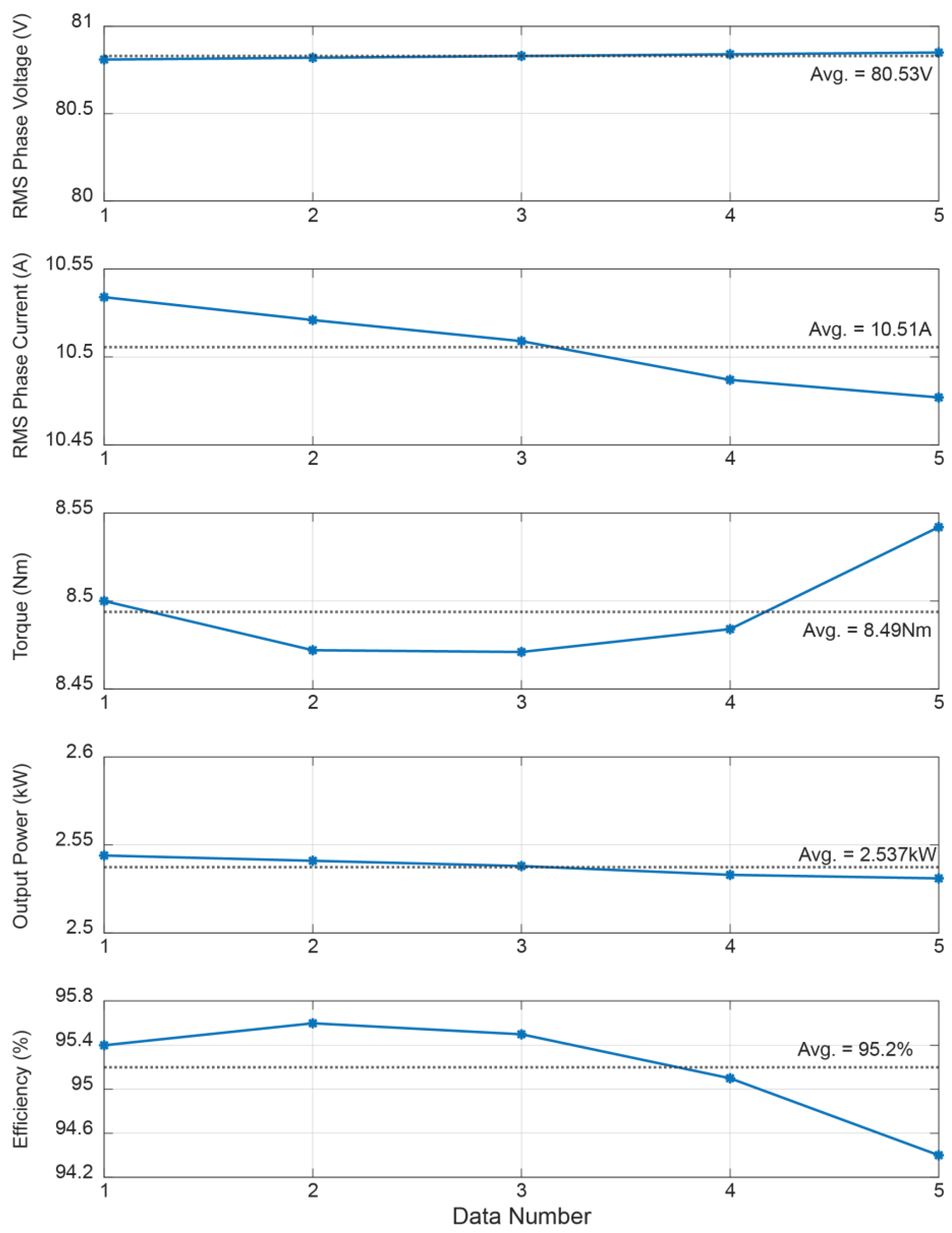
The motor underwent testing not in a conventional laboratory but in a specialized facility that specializes in qualification tests for the market. These tests were specifically conducted at the motor’s rated speed and torque point, aiming for operation at 2.5 kW and 3000 RPM. In total, five tests were carried out, as shown in
Figure 16, where the dotted black line represents the average value. It is noteworthy that, despite some slight variations in results between runs, the target operating point was consistently achieved. The motor’s performance was officially verified through the qualification test, confirming its suitability for practical applications.
As observed in the simulations, the phase current required to achieve the rated torque is 10.5 Arms. However, the actual torque output during testing exceeded the design target, measuring at around 8.5 Nm. This indicates that the motor performed better than expected, delivering higher torque than initially anticipated. Moreover, the efficiency of the motor is shown to be 95.2%, which is 1.6% higher than the previous results in [
29]. This improvement in efficiency can be attributed to the optimization of the motor’s design, especially with the inclusion of the optimized magnetic screen. The comparison between the simulation and experiment results are shown in
Table 3 below.
5. Conclusions
In conclusion, this research presented a novel Dual Air-Gap Surface Permanent Magnet Synchronous Motor (DAG-SPMSM) with a strategically placed magnetic screen in the middle of the rotor. The magnetic screen effectively isolated the outer and inner motors, leading to several noteworthy findings.
Firstly, through extensive finite element analysis (FEA), it was demonstrated that the magnetic screen reduced the air-gap flux density, resulting in a decrease in torque output. However, it was also observed that this reduction in torque was compensated by a substantial decrease in torque ripple, making the motor’s operation smoother and more stable.
Secondly, experimental tests conducted in a specialized qualification test facility provided practical validation of the proposed design. Surprisingly, the motor surpassed the design target, producing a higher torque output than expected, while also exhibiting an improved efficiency of 95.2%—a 1.6% increase compared to previous nonoptimized results.
Furthermore, the magnetic screen influenced the back-EMF waveform, leading to a back-EMF profile that closely resembled a sinusoidal shape with reduced harmonic distortion. This improvement in waveform quality contributes to smoother motor operation and potentially lower noise levels.
Overall, the successful implementation of the proposed DAG-SPMSM with the magnetic screen offers promising advantages in terms of reduced torque ripple, enhanced efficiency, and improved back-EMF characteristics. These results make the motor a strong candidate for various applications requiring high torque density, smooth operation, and increased energy efficiency.


 ,
, 


