Article

A Damping Control Strategy to Improve the Stability of Multi-Parallel Grid-Connected PCSs

College of Electrical Engineering, Zhejiang University, Hangzhou 310027, China
*
Author to whom correspondence should be addressed.
Energies 2023, 16(12), 4633; https://doi.org/10.3390/en16124633
Submission received: 13 April 2023 / Revised: 24 May 2023 / Accepted: 1 June 2023 / Published: 10 June 2023

Abstract

:
In this study, to ensure stable operation of multi-parallel PCSs, a damping control strategy is adopted to restrain resonance characteristics of a parallel system, and the stability of the system is analyzed. First, the mathematical model of a single PCS is built, the capacitive current feedback-type active damping control strategy is introduced, and the effect of the damping control strategy on a single PCS under proportional-integral (PI) control is analyzed. Then, under the presence of grid impedance, a single PCS model is established and extended to multi-parallel PCSs, where a single PCS is replaced by a Norton’s equivalent circuit. The active damping method is developed, and Bode diagrams are utilized to verify that it can effectively suppress the resonance spikes of a parallel system. Finally, a simulation model of four PCSs in parallel operation is built on the Simulink platform, and the results support the correctness of the theoretical analysis.

1. Introduction

Energy storage technology that has the ability to smooth out fluctuations in wind power output and solar energy generation and to improve the grid’s ability to consume new energy has become a current research hotspot. With the spread of renewable energy and distributed generation, an energy storage system generally adopts the structure of multiple power converter systems (PCSs) connected in parallel to the grid; however, as the number of PCSs in parallel increases, various stability problems can arise [1]. The presence in the line of grid impedance leads to the coupling effect as well as interactions between multiple PCSs and between PCSs and the grid, which cause the resonance characteristics of the system to become more complicated [2] under grid-connected conditions.
An energy storage PCS is generally composed of an inverter and an LCL filter. Much research has focused on the stability of LCL-type parallel inverters [2,3,4,5,6,7,8,9,10,11]. A control strategy with active damping has been proposed to suppress resonance [2]. This strategy is based on the Norton equivalent theorem, which considers each inverter to be a controlled current source and an output impedance connected in parallel. Under the assumption that all inverters are the same, using the superposition theorem, parallel inverters can be simplified to a single inverter whose grid-side impedance increases with the number of parallel inverters [3]. In [4], a small-signal model of multi-parallel inverters including current control, voltage feedforward, and pulse width modulation harmonic characteristics was established, and the basic resonance characteristics of the parallel system under the influence of grid impedance were analyzed. In [5], the interaction relationship of parallel inverters with an LCL filter in a weak grid were studied by analyzing the grid-connected current. In order to represent this interaction relationship, the total current was divided into the interactive and common current. In [6], a control strategy of introducing virtual impedance and adding output voltage feedforward in the current loop was proposed; by utilizing a Bode diagram of the inverter’s equivalent output impedance, the stability of the parallel inverters under voltage source control was analyzed. In [7], a stability analysis of grid-connected inverters based on passivity was conducted, and a new point of common coupling (PCC) voltage feedforward method was designed to eliminate the causes of instability for grid-connected inverters. In [8], based on the separation scheme of [5], an analysis was developed in the discrete z domain, and two stability limitations were determined to clarify the causes of the resonant current. In [10], from a passive viewpoint, by utilizing an impedance-based stability analysis method, the instability problem of inverters with the presence of grid impedance was studied, and the harmonic interaction was analyzed. A study by [12] simplified the multi-parallel operation of PCSs to a single-unit operation and used the impedance intersection method to determine the stability of multiple inverters operating in parallel. However, for energy storage systems, each PCS often has different power outputs, making this simplified model unsuitable.
Currently, active damping and passive damping [11,13] are the two main damping methods for solving the PCS parallel resonance problem. The passive damping method involves connecting the filter inductor or the filter capacitor in series or in parallel with a resistor, which has the advantages of simple implementation and not being limited by the switching frequency, but it will produce extra power and reduce the efficiency of the system [8]. The passive damping method involves adding extra damping resistors to a circuit, resulting in additional power loss, which can be avoided by using a virtual resistor to replace the actual resistor to achieve damping of the LCL filter resonance spike [14,15,16]. This type of damping method through a control strategy is called an active damping control method. In addition to utilizing a virtual resistor, control strategies such as lead network, notch filter, and bi-quad filter can achieve active damping of resonance spikes in a system [17]. Although the active damping control method avoids the use of additional devices and no extra losses are generated, the system is more complex to calculate and design. If the capacitive voltage feedback control strategy is adopted, sampling noise has a significant impact on system control due to the existence of differential links, and therefore, it can be transformed into the capacitive current feedback control strategy [14]. In [18], an active damping control method was applied, but there was a lack of comprehensive analysis regarding the specific magnitude of active damping. Therefore, in this paper, we further investigate this aspect based on the existing research.
Here, we analyze the resonance problem of multi-parallel PCSs, we adopt a capacitive current feedback-type active damping control strategy to improve the frequency characteristics and to compensate for the resonance peaks, and we study the stability of multiple parallel PCSs with the active damping control method. This paper is organized as follows: In Section 2, the mathematical model of a single PCS with an LCL filter is built, the design method of the LCL filter is studied, and the stability of a single PCS under the capacitive current feedback-type active damping control strategy is analyzed, and then the single PCS mathematical model is extended to a multiple PCS parallel system mathematical model with grid impedance. The PCS parallel system model with active damping based on the current source equivalent is established, and equivalent models are applied to a small signal analysis at the same time and yield the same conclusions about system stability. The range of values for active damping that can make the system stable is derived, and Bode diagrams are utilized to verify the effectiveness of active damping in suppressing resonance spikes. In Section 3, a simulation model of four parallel 500 kW PCSs is created to demonstrate the correctness of the theoretical analysis.

2. Materials and Methods

2.1. Modeling and Control of a Single PCS

2.1.1. System Modeling

The PCS consisted of a voltage source three-phase full bridge inverter and an LCL filter; its grid-connected topology is shown in Figure 1. In Figure 1, L1, L2, and C are the filter inductors and filter capacitor, respectively; i1 and i2 are the inductor currents flowing through inductor L1 and L2, respectively; ic is the filter capacitor current. The output voltage of the three-phase full bridge circuit is ui; ua, ub, and uc are the grid voltages.
In this paper, the symbols, meanings, and values of various parameters in the PCS system are presented in Table 1.
According to the topology of the grid-connected PCS shown in Figure 1, it can be inferred that, when the three-phase grid voltage is balanced, the three-phase circuit is mutually decoupled, and each phase is an independent circuit, as presented in Figure 2. Based on Figure 2, the transfer function of the LCL filter GLCL(s), namely the transfer function between the input voltage ui and the output current i2, is:
G LCL ( s ) = i 2 u i = 1 L 1 L 2 C s 3 + ( L 1 + L 2 ) s
Accordingly, the Bode diagram of GLCL(s) is depicted in Figure 3, and compared with an L filter. As the figure shows, in the case of the same inductance, the low-frequency gain of the two filters is the same. However, in the high-frequency part, the gain of the LCL filter decays rapidly, which means that the suppression effect of the LCL filter on high-frequency harmonics [17] is far better than that of the L filter. Unfortunately, the gain of the LCL filter has a resonant spike at the resonant frequency, which causes its phase to suddenly decrease by 180°. If this resonance spike is not effectively suppressed, the output current of the grid-connected PCS will oscillate, and the system will even become unstable. Actually, the resonance characteristic of the LCL filter is caused by the lower system damping; therefore, the damping method can effectively handle this type of problem.

2.1.2. LCL Filter Design

An LCL filter has better filtering effect than an L filter, but the design of an LCL filter needs to consider many factors. A reasonable value of an LCL filter can effectively suppress the high-order harmonics of grid-connected current, and can reduce damage, due to electromagnetic interference, to the grid equipment. Meanwhile, the stability of the grid-connected system should be considered in the parameter design [19]. After referring to various filter designs, the parameter selection steps for the LCL filter of the three-phase grid-connected PCS are as follows:
A.
Inverter-side inductor L1
The current flowing through the switch tubes is the current flowing through the inductor L1. In order to reduce the current stress of the switch tubes, the current ripple of the inductor L1 must be limited. Define the ripple factor of the inductor as λL1. According to [20], when the grid frequency is 50 Hz, the minimum value of the inductor L1 should be:
L 1 _ min = 3 4 M r U dc U g λ L 1 f s w P
where Mr is the modulation ratio, Udc is the DC bus voltage, fsw is the carrier frequency of the switching tubes, Ug is the effective value of the grid phase voltages, and P is the total power of the PCS.
B.
Filter capacitor C
In an LCL filter, the value of the filter capacitor C decides the amount of reactive power introduced and determines the size of the current flowing through the inductor L1 and the switch tubes, and therefore, has an impact on the switching tube conduction loss [21]. When designing capacitor C, the ratio of active power to output-rated active power λc is usually introduced, and the maximum value of the filter capacitor C is [22]:
C = λ c P 3 ω n U g 2
where λ c 5 % ω n is the grid angular frequency.
C.
Grid-side inductor L2
The value of the inductance L2 should be moderate, because, if it is too large, the inductance will reduce the dynamic response speed of the system, and if it is too small, the inductance will increase the system loss. Considering, comprehensively, that the grid-side inductance L2 and the inverter-side inductance L1 satisfy the following relationship:
L 1 = k L 2
when k is between 4 and 6, the effect of inductance distribution and capacitance matching is best.
Considering the characteristics of the LCL filter to eliminate switching frequency harmonics, the switching frequency is greater than the resonant frequency. In addition, the purpose of an LCL filter is to filter out all the harmonics above the fundamental. If the resonant frequency is close to the fundamental wave frequency, it will increase the quantity of filter elements, which does not reflect the advantage of the third-order control system of an LCL filter. Combining the above two factors, the resonant frequency of the LCL filter is designed to satisfy [23]:
10   f n f r e s = 1 2 π L 1 + L 2 L 1 L 2 C 0.5   f s w
where f n is the grid frequency, f r e s is the resonant frequency of the LCL filter, and f s w is the PCS switching frequency.

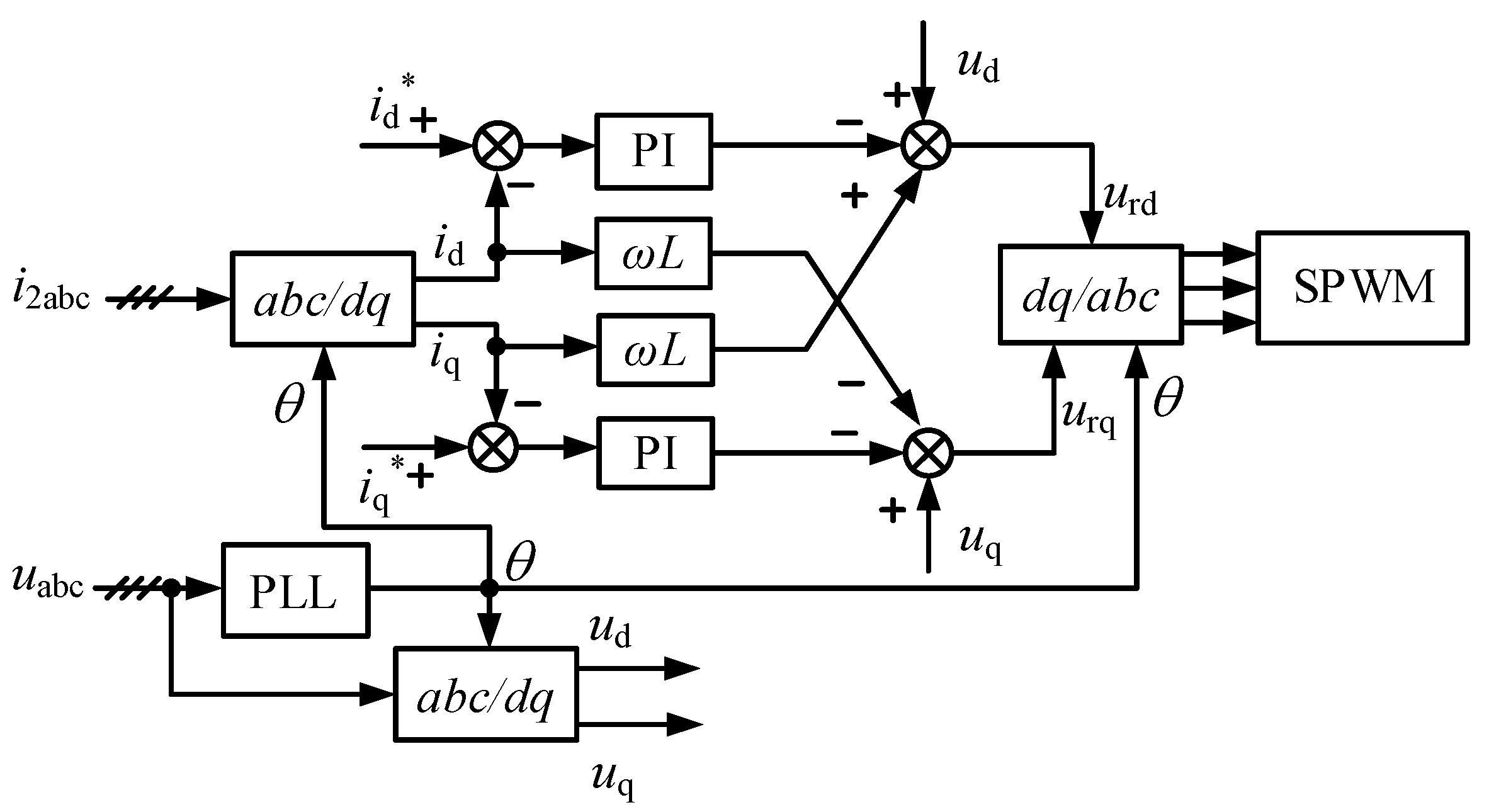
2.1.3. Control Strategy

A PI control strategy based on current feedforward decoupling is adopted for the grid-connected PCS [24,25], and the control structure diagram is shown in Figure 4.
In Figure 4, i2abc represents the three-phase grid-connected current, uabc is the three-phase grid voltage, and inductor L = L1 + L2. The grid-side voltage uabc gained by sampling is locked through a three-phase phase-locked loop (PLL) to obtain the grid voltage phase. The instantaneous active current component id and the reactive current component iq of the grid-side current i2abc can be acquired by transforming the coordinate system from abc to dq for the grid-side current i2abc. The errors between the active current reference id*, the reactive current reference iq*, and the actual values id and iq are adjusted by the PI controller. Then, through decoupling feedback, the reference voltages urd and urq in the dq coordinate system are output.
As mentioned above, an LCL filter has a resonance problem. If the resonance is not suppressed, the current closed-loop system may not be stable. The traditional method is the passive damping method, that is, filter resistors connected with the inductor in series (parallel) or the capacitor in series (parallel) are added to the filter. However, the addition of a filter resistor increases the cost of a system; meanwhile, due to active power loss through the filter resistor, the efficiency of the system is reduced. The heating problem of a filter resistor is also another adverse factor limiting its practical application. Compared with the passive damping method, although the introduction of sensors leads to control complexity and higher cost of the system, the active damping method has attracted more attention because of no additional power loss [27]. In this paper, a capacitive current feedback-type active damping control strategy is adopted.
Figure 5 is the control block diagram of the grid-connected PCS current loop when capacitive current feedback control is introduced [8], where i2_ref represents the reference of grid-connected current i2; GPI(s) is the PI controller, and its transfer function expression is kp + ki/s; KPWM represents the gain of the PCS, and its value is set to 1 in this paper; Hi is the feedback coefficient of capacitor current. The current reference values idref and iqref can be obtained from the power reference values.
The equivalent transformation of the control block diagram shown in Figure 5 can result in a simplified control block diagram, as shown in Figure 6, where:
{ G k 1 ( s ) = K pwm G PI ( s ) s 2 L 1 C + s C K pwm H i + 1 G k 2 ( s ) = s 2 L 1 C + s C K pwm H i + 1 s 3 L 1 L 2 C + s 2 L 2 C K pwm H i + s ( L 1 + L 2 )
The loop gain of the above closed loop system is:
T A ( s ) = G k 1 ( s ) G k 2 ( s ) = K pwm G PI ( s ) s 3 L 1 L 2 C + s 2 L 2 C K pwm H i + s ( L 1 + L 2 )
The current on the grid side is:
I 2 ( s ) = T A ( s ) 1 + T A ( s ) I 2 ref ( s ) G k 2 ( s ) 1 + T A ( s ) U g ( s )
According to Equation (7), the Bode diagram of the system loop gain before and after adopting active damping control can be obtained, as shown in Figure 7. It can be observed from Figure 7 that Hi has little effect on the amplitude-frequency characteristics of the low-frequency and high-frequency system, but the amplitude-frequency and phase-frequency characteristics of the system near the resonant frequency fr are significantly improved, and the resonant amplitude at fr is significantly suppressed, which can prove that utilization of the active damping control method can help the LCL filter to effectively restrain the resonance spike, and therefore, improve the stability of the system.
Based on Equation (8), a single PCS can be replaced by a Norton’s equivalent circuit in the admittance form [2], as shown in Figure 8, where I*(s) is the equivalent current source, Teq(s) is the equivalent admittance, and
{ I * ( s ) = T A ( s ) 1 + T A ( s ) I 2 ref ( s ) T eq ( s ) = G k 2 ( s ) 1 + T A ( s )

2.2. Modeling and Stability Analysis of Multi-Parallel PCSs

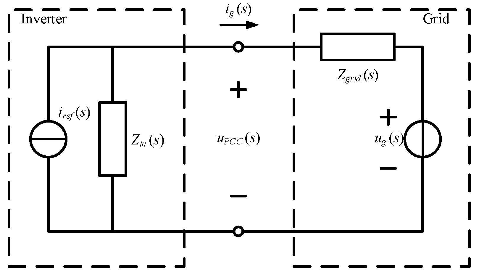
2.2.1. System Modeling

Compared with the ideal grid-connection situation of the single PCS in Section 2, the grid-connection voltage of each PCS in parallel operation is no longer the ideal voltage, but upcc. The equivalent circuit of multiple PCSs connected to the grid in parallel is shown in Figure 9. In the figure, Z1i, Z2i, and Z3i (i = 1, …, n) represent the impedances of the LCL filter of the i-th PCS. Subscripts 1, 2, and 3 represent the inductors and capacitor, respectively; Zg is the grid impedance; uii are PCS output voltages; ug is the grid voltage; ii are the grid-side currents; ig is the grid-connected current.
Based on the equivalent circuit shown in Figure 9, the relationship between the grid-side current ii of each PCS and the PCS output voltages uii and the grid voltage ug can be expressed by a matrix [3]:
( i 1 i 2 i n ) = ( G 11 G 12 G 1 n G 21 G 22 G 2 n       G i j G n 1 G n 2 G n n ) ( u i 1 u i 2 u i n ) + ( H 1 H 2 H n ) u g
In the given context, Gij and Hi are equivalent admittance parameters. Gij represents the equivalent admittance parameters of the PCS output voltage uij when it acts alone and generates the grid-side current ii. Hi represents grid voltage ug acting alone on the current ii.
In practice, energy storage power stations are often designed modularly; therefore, it can be reasonably assumed that all the parameters of each PCS in the parallel system are the same [3], including their hardware and software parameters. Then, the impedances of the LCL filters can be expressed as:
{ Z 11 = Z 12 = = Z 1 n = Z 1 Z 21 = Z 22 = = Z 2 n = Z 2 Z 31 = Z 32 = = Z 3 n = Z 3 { Z 1 = L 1 s Z 2 = L 2 s Z 3 = 1 / C s
According to the above assumption, all diagonal elements are uniform, denoted as G1, and all non-diagonal elements of the matrix are also uniform, denoted as G2. Likewise, Hi can be denoted as H1. Through the superposition principle and circuit simplification, elements G1, G, and H1 can be derived, as given in Equation (12):
{ G 1 = i 1 u i 1 = Z 3 Z + ( n 1 ) Z 3 Z g ( Z 1 + Z 3 ) Z ( Z + n Z g ( Z 1 + Z 3 ) ) G 2 = i 1 u i 2 = Z 3 Z g ( Z 1 + Z 3 ) Z ( Z + n Z g ( Z 1 + Z 3 ) ) H 1 = i 1 u g = Z 1 + Z 3 Z + n Z g ( Z 1 + Z 3 ) Z = Z 1 Z 2 + Z 1 Z 3 + Z 2 Z 3
For the first PCS, G1, G2, and H1, respectively, represent the transfer function between the grid-side current i1 and the excitation sources ui1, ui2 ~ uin, and ug when these excitation sources act alone, which is similar to other PCS.
Figure 10 shows the Bode diagram of G1(s), G2(s), and H1(s) when the number of parallel PCSs is three. The parameters required for the figure are selected according to Table 1. The Bode diagram reveals that without introducing an active damping strategy, when the excitation sources ui1 and ui2 ~ uin act separately, three resonance spikes appear in the circuit. Moreover, when the excitation source ug acts alone, the frequency response curve of the system contains two resonance spikes. The existence of these resonance spikes can destabilize the circuit. Based on the above Bode diagram, the resonance characteristics of the PCS parallel system can be obtained and used to analyze the stability of the system, and therefore, adopt corresponding control strategies to suppress the resonance peaks and to ensure stable operation of the system.

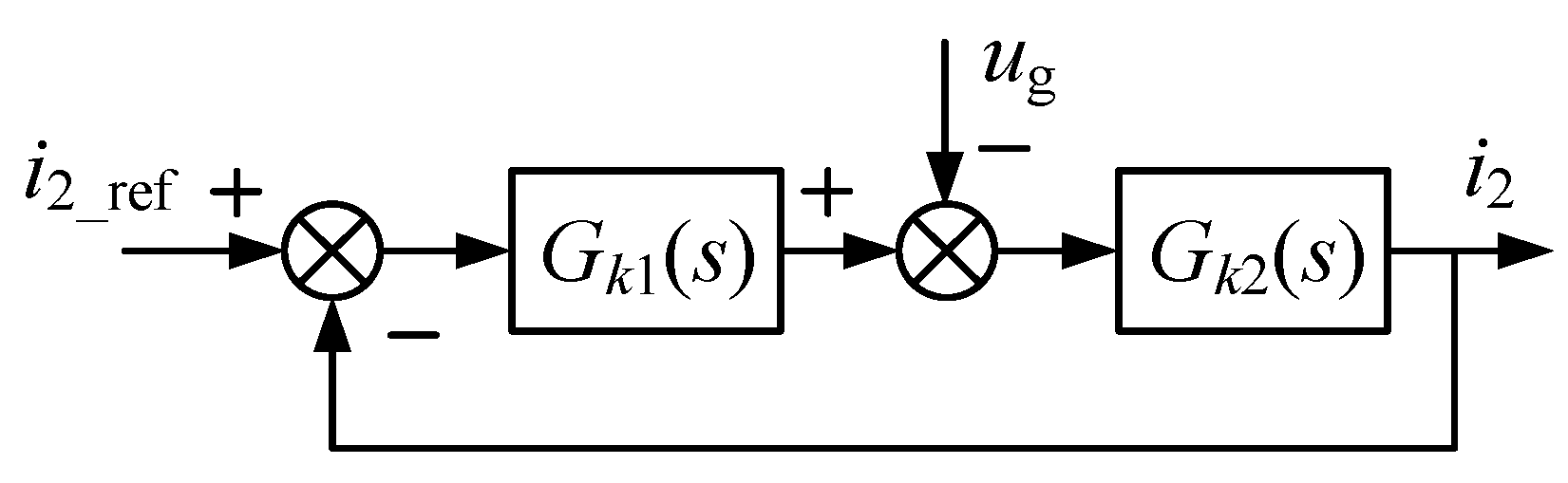
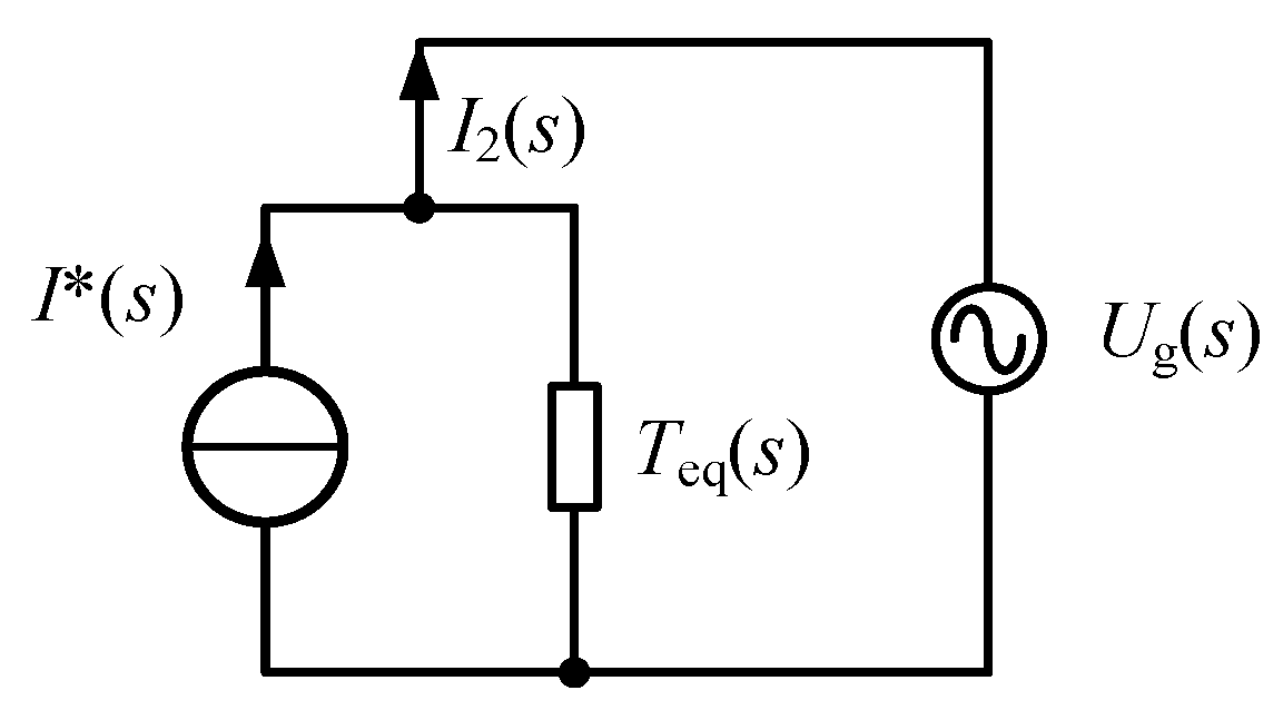
2.2.2. Small Signal Model Analysis

An LCL filter grid-connected inverter is a complex system, characterized by high-order, strong coupling, and nonlinearity. To simplify its analysis, a small signal model is used to linearize the system around its steady-state operating point. Figure 11 [28] shows the small-signal model of the three-phase LCL-type PCS, where the inverter and filtering system can be represented as a Norton circuit, and the grid side can be represented as a Thevenin circuit consisting of an ideal voltage source ug(s) and grid impedance Zgrid(s) in series. The inverter is equivalent to the parallel form of an ideal current source iref(s) and the output impedance Zin(s). The voltage at the common coupling point is denoted as uPCC(s).
According to Figure 11, the grid-connected current ig(s) expression can be obtained as:
i g ( s ) = Z inv   ( s ) Z inv   ( s ) + Z grid   ( s ) i ref   ( s ) 1 Z inv   ( s ) + Z grid   ( s ) u g ( s )
In the PCS, the grid voltage ug(s) is typically considered to be constant and does not vary with the system. The equivalent current source is set to a reference value at the steady-state operating point and remains constant thereafter. Additionally, the equivalent impedance Zin(s) of the inverter is typically assumed to be constant and not affected by changes in the grid impedance. This assumption is made to simplify the calculations and is often used in practice.
Therefore, a change in current ig(s) is only related to a change in the expression 1 / ( 1 + Z grid ( s ) / Z inv ( s ) ) , as F(s),
i g ( s ) = [ i ref ( s ) u g ( s ) Z inv ( s ) ] · 1 1 + Z grid ( s ) / Z inv ( s ) = [ i ref ( s ) u g ( s ) Z inv ( s ) ] · F ( s )
The simplified control block diagram of the two current control structures is illustrated in Figure 12 after simplifying the control system diagram.
The transfer function without active damping (i = 1) can be obtained:
{ G x 1 ( s ) = K p w m G PI ( s ) s 2 L 1 C + 1 G y 1 ( s ) = s 2 L 1 C + 1 s 3 L 1 L 2 C + s ( L 1 + L 2 ) T 1 ( s ) = 1
The transfer function with active damping (i = 2) can be obtained as follows:
{ G x 2 ( s ) = K pwm G PI ( s ) s 2 L 1 C + s C K pwm H i + 1 G y 2 ( s ) = s 2 L 1 C + s K pwm C H i + 1 s 3 L 1 L 2 C + s 2 L 2 C K pwm H i + s ( L 1 + L 2 ) T 2 ( s ) = 1
Based on Figure 12, the current loop control block diagram is simplified without utilizing the small-signal model and Equation (15). As a result, the transfer function of the current ig(s) can be expressed as follows:
i g = G x 1 G y 1 1 + G x 1 G y 1 T 1 i ref G y 1 1 + G x 1 G y 1 T 1 u g = K pwm G PI ( s ) s 3 L 1 L 2 C + s ( L 1 + L 2 ) + K pwm G PI ( s ) i ref s 2 L 1 C + 1 s 3 L 1 L 2 C + s ( L 1 + L 2 ) + K pwm G PI ( s ) u g
Based on Figure 12, the current loop control block diagram is simplified by incorporating the small-signal model and Equation (16). This allows us to derive the transfer function of the current ig(s) as follows:
i g = G x 2 G y 2 1 + G x 2 G y 2 T 2 i ref G y 2 1 + G x 2 G y 2 T 2 u g = K pwm G PI ( s ) s 3 L 1 L 2 C + s 2 L 2 C K pwm H i + s ( L 1 + L 2 ) + K pwm G PI ( s ) i ref s 2 L 1 C + s C K pwm G PI ( s ) + 1 s 3 L 1 L 2 C + s 2 L 2 C K pwm H i + s ( L 1 + L 2 ) + K pwm G PI ( s ) u g
Thus, the ratio of the grid impedance to the equivalent output impedance of the inverter under closed-loop current control with and without capacitive current feedback can be expressed as:
f 1 ( s ) = s 3 L 1 L 2 C + s ( L 1 + L 2 ) K pwm G PI ( s )
f 2 ( s ) = s 3 L 1 L 2 C + s 2 L 2 C K pwm H i + s ( L 1 + L 2 ) g K pwm G PI ( s )
Judging the stable state of Equation (14) is equivalent to judging whether F(s) is stable. F(s) can be seen as a negative feedback loop with a forward path gain of 1 and a feedback loop gain of f ( s ) = Z grid   ( s ) / Z inv   ( s ) . Thus, we can conclude that:
(1)
If the grid is strong (high independence), f(s) is close to 0 and F(s) is close to 1, meaning the system is always stable.
(2)
If the grid is weak (low independence), the system is only stable if certain conditions are met by f(s).
Given the above, the analysis of the stability of the grid-connected inverter can be simplified as the analysis of the stability of f(s). However, F ( s ) = 1 / ( 1 + Z grid   ( s ) / Z inv   ( s ) ) can be regarded to be the unit negative of the forward path gain of 1 / f ( s ) .
In the feedback system, according to the principle of open-loop analysis and a closed-loop system, by analyzing 1 / f ( s ) , the stability of F(s) can be obtained, and then the stability of the grid-connected inverter system can be observed.
After analyzing the above, it is evident that the stability of f(s) is primarily determined by the value of Hi when the PCS structure remains unchanged. By comparing (8) and Equation (18), it can be observed that the current expression derived from the small signal modeling method is entirely consistent. Therefore, it can be concluded that the stability analysis results obtained from both methods are identical.

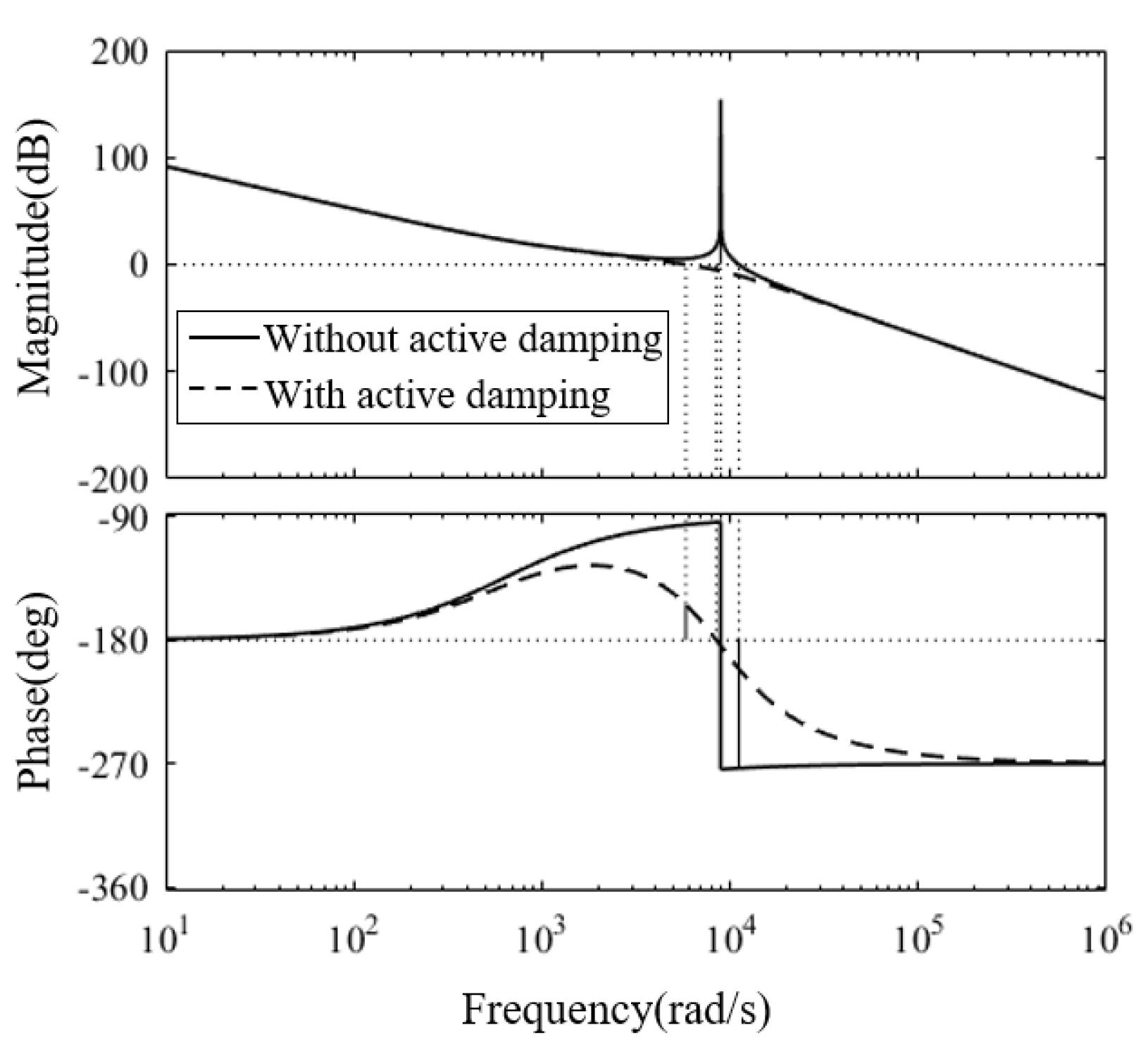
2.2.3. Stability Analysis

According to the above, after introducing the capacitive current feedback-type active damping control strategy, a single PCS can be replaced by a Norton’s equivalent circuit in admittance form. Based on this, each PCS in a parallel system can be replaced by a circuit where a current source is connected in parallel with the output impedance, and then all the PCSs in parallel are connected to the grid through the grid equivalent impedance [2]. The equivalent topology is shown in Figure 13.
In Figure 13, Ii*(s) (i = 1, …, n) represents the equivalent current source of the i-th PCS, Teq(s) is the equivalent admittance. It is assumed that all PCSs are the same; therefore, the equivalent admittance is the same. According to the superposition theorem, taking the first PCS as an example, the grid-side current can be obtained as follows:
I 1 ( s ) = I 1 * ( s ) ( 1 Z g ( s ) T eq ( s ) n Z g ( s ) T eq ( s ) + 1 ) i = 2 n I i * ( s ) Z g ( s ) T eq ( s ) n Z g ( s ) T eq ( s ) + 1 U g ( s ) T eq ( s ) n Z g ( s ) T eq ( s ) + 1
It is clear that Equation (21) has three independent terms. For the first PCS, these three terms, respectively, represent the transfer function between the grid-side current I1(s) and the excitation sources I1*(s), I2*(s)~In*(s), and Ug(s) when these excitation sources act alone, which is similar to other PCSs.
From (9), the mathematical relationship between the equivalent current source and the current reference value is given in Equation (22), and then through Equation (21), the mathematical relationship between the grid-side current I1(s) and the current reference values I1ref(s) and I2ref(s) can be obtained. On this basis, the Bode diagram of the transfer function between the grid-side current I1(s) and the current reference values I1ref(s) and I2ref(s) and the voltage source Ug(s) can be depicted, as presented in Figure 14. The parameters required for the figure are selected according to Table 1.
I i * ( s ) = T A ( s ) 1 + T A ( s ) I i ref ( s )
According to the method of judging the stability of the system by using the Bode diagram, if the phase margin and amplitude margin are greater than 0 at the same time, the system is stable; otherwise, the system is unstable. As Figure 14 shows, by utilizing the active damping method, the resonances of PCS1 are effectively suppressed. The ability of active damping control to suppress the resonant spikes of the parallel systems is proven, and this method can significantly improve the operation stability of a parallel system.
In Equation (21), let i = 2 n I i * = m I 1 * , the grid connection current can be expressed as:
I 1 ( s ) = I 1 * ( s ) ( n 1 m ) Z g ( s ) T eq ( s ) + 1 n Z g ( s ) T eq ( s ) + 1 U g ( s ) T eq ( s ) n Z g ( s ) T eq ( s ) + 1
Substituting Equation (9) into Equation (23), it can be concluded that system’s stability depends on the pole distribution of G K 2 ( s ) , 1 1 + T A s , and 1 / ( n Z g ( s ) G K 2 ( s ) + 1 + T A ( s ) ) . The presence of G K 2 (s) does not impact the system’s stability, while the polar distribution of 1 / ( 1 + T A ( s ) ) is solely determined by the internal parameters of an individual PCS [2]. The pole distribution of 1 / ( n Z g ( s ) G K 2 ( s ) + 1 + T A ( s ) ) is associated with the grid impedance and the number of parallel PCSs, and now, the stability of the system is only related to the distribution of its poles. The presence of a resistor increases the system damping, and in order to conduct the study in the worst case of zero passive damping, the parasitic resistance of the net-side inductor is neglected, and therefore, Z g ( s ) = s L g . By substituting G K 2 ( s ) and T A ( s ) into 1 / ( n Z g ( s ) G K 2 ( s ) + 1 + T A ( s ) ) , it yields:
1 n Z g ( s ) G k 2 ( s ) + 1 + T A ( s ) = s 4 L 1 L 2 C + s 3 C H i L 2 + s 2 ( L 1 + L 2 ) s 4 L 1 ( L 2 + n L g ) C + s 3 C H i ( L 2 + n L g ) + s 2 ( L 1 + L 2 + n L g ) + s k p + k i
Therefore, the constraints of Hi can be derived to ensure the stability of the system by using the Routh criterion [29]:
{ H i < 2 k p L 1 ( L 1 + L 2 + n L g ) ( L 1 + L 2 + n L g ) 2 4 k i L 1 ( L 2 + n L g ) C H i > 2 k p L 1 ( L 1 + L 2 + n L g ) + ( L 1 + L 2 + n L g ) 2 4 k i L 1 ( L 2 + n L g ) C

3. Results and Discussion

To validate the correctness of the above theoretical analysis, simulations were conducted on the MATLAB/Simulink platform. A simulation system model with four PCSs in parallel was built. The simulation parameters of each PCS are presented in Table 1.
Figure 15 presents the waveform of the grid-connected current of a single PCS without adopting active damping control. It can be clearly observed from Figure 15 that when no active damping is introduced, the grid-connected current distortion is severe due to the resonance problem of the parallel circuit. In Figure 16, as the active damping control strategy is adopted to the parallel system, the waveform of the grid-connected current has no significant distortion, and it presents a sinusoidal waveform and maintains the same phase with the grid voltage. Figure 17 shows the THD analysis of the grid-connected current. It can be concluded that the current is highly sinusoidal, the distortion rate remains at about 0.19%, and the control effect is significant.
Then, the simulation model was extended to four PCSs connected in parallel and capacitive current proportional feedback control was adopted. The waveforms of the grid-connected current and voltage are recorded in Figure 18, and the THD analysis of the current is presented in Figure 19. As shown in Figure 19, the current is highly sinusoidal, and the distortion rate remains at about 1.35%. It proves that the application of an active damping control strategy can effectively strengthen the stability of the system by increasing the damping of the parallel circuit.
Utilization of the capacitive current feedback-type active damping control strategy improves the frequency characteristics and compensates for the resonance peaks, which improves the stability of the system. From the above simulation results, when the capacitor current feedback coefficient Hi is 5, the harmonics of the grid-connected current can be effectively suppressed, and the stability of the parallel system is significantly improved. However, when active damping control is applied, it is necessary to select an appropriate value of Hi to obtain a better harmonic suppression effect. The Bode diagram of the transfer function for PCS1 when the value of Hi is 2 is presented in Figure 20. It can be observed from the Bode diagram that the system is in an unstable operating state at this time. Meanwhile, the grid-connected current of four PCSs is depicted in Figure 21. It can be concluded that the waveform of the grid-connected current oscillates and has large harmonics. Consequently, the results of the Bode diagram of the transfer function are consistent with the simulation results. According to the results obtained above, Bode diagrams of the system can be drawn when Hi takes different values, and then the influence of Hi on system stability can be evaluated to obtain the appropriate value of Hi in practical application.

4. Conclusions

In this paper, we analyze the resonance problem of multi-parallel PCSs, and adopt on active damping control strategy of capacitive current proportional feedback to improve the frequency characteristics and to compensate for the resonance peaks. Theoretically, first, we established a single PCS mathematical model from the perspective of a single PCS, analyzed the design method of the LCL filter, and introduced the active damping control strategy of capacitor current feedback to improve its amplitude-frequency characteristics. Then, the model was extended to multiple parallel PCSs and connected to the grid through the grid impedance. The parallel system of multiple PCSs was established based on Norton’s equivalent circuit. The stability of the system was verified by using Bode diagrams. After introducing the active damping control strategy, we found that the resonant peaks of the multi-parallel PCSs were effectively suppressed. Furthermore, the same conclusion was reached by analyzing small signal models. Finally, the effectiveness of the proposed method was verified by using a simulation model. A circuit model consisting of four PCSs in parallel was built, and the results revealed that the active damping method could compensate for the resonance peaks and improve the stability of the system, and could also effectively reduce the grid-connected current distortion rate and improve the power quality.

Author Contributions

Conceptualization, X.X. and W.Y.; methodology, W.Y.; software, X.X., validation, X.X. and W.Y.; formal analysis, W.Y.; investigation, G.X.; resources, W.Y.; data curation, W.Y.; writing—original draft preparation, X.X. and W.Y.; writing–review and editing, W.Y.; visualization, G.X.; supervision, W.Y.; project administration, W.Y.; funding acquisition, W.Y. All authors have read and agreed to the published version of the manuscript.

Funding

This work was supported by the National Natural Science Foundation of China under project 52077197.

Conflicts of Interest

The authors declare no conflict of interest.

References

  1. Qian, Q.; Xie, S.; Huang, L.; Xu, J.; Zhang, Z.; Zhang, B. Harmonic Suppression and Stability Enhancement for Parallel Multiple Grid-Connected Inverters Based on Passive Inverter Output Impedance. IEEE Trans. Ind. Electron. 2017, 64, 7587–7598. [Google Scholar] [CrossRef]
  2. He, J.; Li, Y.W.; Bosnjak, D.; Harris, B. Investigation and Active Damping of Multiple Resonances in a Parallel-Inverter-Based Microgrid. IEEE Trans. Power Electron. 2013, 28, 234–246. [Google Scholar] [CrossRef]
  3. Agorreta, J.L.; Borrega, M.; López, J.; Marroyo, L. Modeling and Control of N-Paralleled Grid-Connected Inverters with LCL Filter Coupled due to Grid Impedance in PV Plants. IEEE Trans. Power Electron. 2011, 26, 770–785. [Google Scholar] [CrossRef]
  4. Siva Prasad, J.S.; Narayanan, G. Minimization of Grid Current Distortion in Parallel-Connected Converters through Carrier Interleaving. IEEE Trans. Ind. Electron. 2014, 61, 76–91. [Google Scholar] [CrossRef]
  5. Lu, M.; Wang, X.; Loh, P.C.; Blaabjerg, F. Interaction and aggregated modeling of multiple paralleled inverters with LCL filter. In Proceedings of the 2015 IEEE Energy Conversion Congress and Exposition (ECCE), Montreal, QC, Canada, 20–24 September 2015; pp. 1954–1959. [Google Scholar]
  6. He, J.; Li, Y.W. Generalized Closed-Loop Control Schemes with Embedded Virtual Impedances for Voltage Source Converters with LC or LCL Filters. IEEE Trans. Power Electron. 2012, 27, 1850–1861. [Google Scholar] [CrossRef]
  7. Xie, C.; Li, K.; Zou, J.; Guerrero, J.M. Passivity-Based Stabilization of LCL-Type Grid-Connected Inverters via a General Admittance Model. IEEE Trans. Power Electron. 2020, 35, 6636–6648. [Google Scholar] [CrossRef]
  8. Lu, M.; Wang, X.; Loh, P.; Blaabjerg, F. Resonance Interaction of Multiparallel Grid-Connected Inverters with LCL Filter. IEEE Trans. Power Electron. 2017, 32, 894–899. [Google Scholar] [CrossRef]
  9. Li, X.; Xing, X.; Qin, C.; Zhang, C.; Zhang, G. Design and Control Method to Suppress Resonance Circulating Current for Parallel Three-Level Rectifiers with Modified LCL Filter. IEEE Trans. Ind. Electron. 2021, 68, 7012–7023. [Google Scholar] [CrossRef]
  10. Yoon, C.; Bai, H.; Beres, R.N.; Wang, X.; Bak, C.L.; Blaabjerg, F. Harmonic stability assessment for multiparalleled, grid-connected inverters. IEEE Trans. Sustain. Energy 2016, 7, 1388–1397. [Google Scholar] [CrossRef] [Green Version]
  11. Wang, X.; Blaabjerg, F.; Loh, P.C. Passivity-based stability analysis and damping injection for multi-paralleled voltage source converters with LCL filters. IEEE Trans. Power Electron. 2017, 32, 8922–8935. [Google Scholar] [CrossRef] [Green Version]
  12. Teng, Y.; Wang, X.; Yu, H.; Yin, Q.; Ruan, X. Impedance regulation method to enhance robustness of LCL grid-connected inverter against grid impedance. Chin. J. Electr. Eng. 2015, 35 (Suppl. S1), 197–204. [Google Scholar]
  13. Wu, W.; He, Y.; Tang, T.; Blaabjerg, F. A New Design Method for the Passive Damped LCL and LLCL Filter-Based Single-Phase Grid-Tied Inverter. IEEE Trans. Ind. Electron. 2013, 60, 4339–4350. [Google Scholar] [CrossRef]
  14. Dong, D.; Wen, B.; Boroyevich, D.; Mattavelli, P.; Xue, Y. Analysis of phase-locked loop low-frequency stability in three-phase grid-connected power converters considering impedance interactions. IEEE Trans. Ind. Electron. 2015, 62, 310–321. [Google Scholar] [CrossRef]
  15. Chen, X.; Zhang, Y.; Wang, S.; Chen, J.; Gong, C. Impedance-phased dynamic control method for grid-connected inverters in a weak grid. IEEE Trans. Power Electron. 2017, 32, 274–283. [Google Scholar] [CrossRef]
  16. Lin, X.; Yu, J.; Yu, R.; Zhang, J.; Yan, Z.; Wen, H. Improving Small-Signal Stability of Grid-Connected Inverter under Weak Grid by Decoupling Phase-Lock Loop and Grid Impedance. IEEE Trans. Ind. Electron. 2022, 69, 7040–7053. [Google Scholar] [CrossRef]
  17. Tang, Y.; Loh, P.C.; Wang, P.; Choo, F.H.; Gao, F.; Blaabjerg, F. Generalized Design of High Performance Shunt Active Power Filter with Output LCL Filter. IEEE Trans. Ind. Electron. 2012, 59, 1443–1452. [Google Scholar] [CrossRef]
  18. Tang, M.; Pei, Z.; Shen, Y.; Wang, Q. Modeling and Stability Analysis of Multi-parallel Grid-Connected PCSs. In Proceedings of the 2021 IEEE/IAS Industrial and Commercial Power System Asia (I&CPS Asia), Chengdu, China, 18–21 July 2021; pp. 95–99. [Google Scholar]
  19. Liserre, M.; Blaabjerg, F.; Hansen, S. Design and Control of an LCL-Filter-Based Three-Phase Active Rectifier. IEEE Trans. Ind. Appl. 2005, 41, 1281–1291. [Google Scholar] [CrossRef]
  20. Ruan, X.; Wang, X.; Pan, D.; Yang, D.; Li, W.; Bao, C. Control Techniques for LCL-Type Grid-Connected Inverters; Springer Nature: Singapore, 2018; pp. 31–61. [Google Scholar]
  21. Dursun, M.; Döşoğlu, M.K. LCL Filter Design for Grid Connected Three-Phase Inverter. In Proceedings of the 2018 2nd International Symposium on Multidisciplinary Studies and Innovative Technologies (ISMSIT), Ankara, Turkey, 9–21 October 2018; pp. 1–4. [Google Scholar]
  22. Timbus, A.V.; Rodriguez, P.; Teodorescu, R.; Ciobotaru, M. Line Impedance Estimation Using Active and Reactive Power Variations. In Proceedings of the 2007 IEEE Power Electronics Specialists Conference, Orlando, FL, USA, 17–21 June 2007; pp. 1273–1279. [Google Scholar]
  23. Liu, F.; Zhou, Y.; Duan, S.; Yin, J.; Liu, B.; Liu, F. Parameter Design of a Two-Current-Loop Controller Used in a Grid-Connected Inverter System with LCL Filter. IEEE Trans. Ind. Electron. 2009, 56, 4483–4491. [Google Scholar]
  24. Xin, Z.; Wang, X.; Loh, P.C.; Blaabjerg, F. Grid-current feedback control for LCL-filtered grid converters with enhanced stability. IEEE Trans. Power Electron. 2017, 32, 3216–3228. [Google Scholar] [CrossRef]
  25. Cavazzana, F.; Caldognetto, T.; Mattavelli, P.; Corradin, M.; Toigo, I. Analysis of Current Control Interaction of Multiple Parallel Grid-Connected Inverters. IEEE Trans. Sustain. Energy 2018, 9, 1740–1749. [Google Scholar] [CrossRef]
  26. Nasiri, M.; Mobayen, S.; Faridpak, B.; Fekih, A.; Chang, A. Small-Signal Modeling of PMSG-Based Wind Turbine for Low Voltage Ride-through and Artificial Intelligent Studies. Energies 2020, 13, 6685. [Google Scholar] [CrossRef]
  27. Pan, D.; Ruan, X.; Wang, X.; Yu, H.; Xing, Z. Analysis and design of current control schemes for LCL-type grid-connected inverter based on a general mathematical model. IEEE Trans. Power Electron. 2017, 32, 4395–4410. [Google Scholar] [CrossRef]
  28. Sun, J. Impedance-based stability criterion for grid-connected inverters. IEEE Trans. Power Electron. 2011, 26, 3075–3078. [Google Scholar] [CrossRef]
  29. Pokharel, M.; Ho, C.N.M. Stability Analysis of Power Hardware-in-the-Loop Architecture with Solar Inverter. IEEE Trans. Ind. Electron. 2021, 68, 4309–4319. [Google Scholar] [CrossRef]
Figure 1. The topology of the grid-connected PCS.
Energies 16 04633 g001
Figure 2. Equivalent circuit of the grid-connected PCS.
Energies 16 04633 g002
Figure 3. The Bode diagram of GLCL(s).
Energies 16 04633 g003
Figure 4. Control structure of a grid-connected PCS [26].
Energies 16 04633 g004
Figure 5. Control block diagram of a PCS current loop [8].
Energies 16 04633 g005
Figure 6. Equivalent block diagram of a PCS current loop.
Energies 16 04633 g006
Figure 7. Bode diagram of the open-loop transfer function of a PCS current loop.
Energies 16 04633 g007
Figure 8. Norton equivalent circuit of a single PCS.
Energies 16 04633 g008
Figure 9. The equivalent model of n-parallel PCSs.
Energies 16 04633 g009
Figure 10. Bode diagram of G1(s), G2(s), and H1(s).
Energies 16 04633 g010
Figure 11. Small-signal model of a PCS [28].
Energies 16 04633 g011
Figure 12. Simplified control diagram of a current loop.
Energies 16 04633 g012
Figure 13. Norton’s equivalent circuit of a PCS parallel system [11].
Energies 16 04633 g013
Figure 14. Bode diagram of the transfer function for PCS1.
Energies 16 04633 g014
Figure 15. Grid-connected current of a single PCS without active damping.
Energies 16 04633 g015
Figure 16. Grid-connected current and voltage of a single PCS with active damping.
Energies 16 04633 g016
Figure 17. Grid-connected current harmonic distortion rate of a single PCS with active damping.
Energies 16 04633 g017
Figure 18. Grid-connected current and voltage of four parallel PCSs.
Energies 16 04633 g018
Figure 19. Grid-connected current harmonic distortion of four parallel PCSs.
Energies 16 04633 g019
Figure 20. Bode diagram of the transfer function for PCS1 when the value of Hi is 2.
Energies 16 04633 g020
Figure 21. Grid-connected current for four PCSs when the value of Hi is 2.
Energies 16 04633 g021
Table 1. Simulation parameters.
SymbolsMeaningsValues
PPower rating500 kW
UgRMS of grid phase voltage220 V
UdcDC side voltage780 V
L1PCS side filter inductor0.25 mH
L2Grid side filter inductor0.08 mH
CFilter capacitor220 uF
LgGrid-connected inductor0.003 mH
HiCapacitor current feedback coefficient5
fswPCS switching frequency10 kHz
kpCurrent controller proportional coefficient10
kiCurrent controller integral coefficient1000
Disclaimer/Publisher’s Note: The statements, opinions and data contained in all publications are solely those of the individual author(s) and contributor(s) and not of MDPI and/or the editor(s). MDPI and/or the editor(s) disclaim responsibility for any injury to people or property resulting from any ideas, methods, instructions or products referred to in the content.

