1. Introduction
In the context of the double carbon strategy, the issues of energy resource depletion and air pollution are pressing, and the employment of renewable and green clean energy has become a global priority [
1,
2]. However, it is important to note that the unique intermittence and instability of renewable energy have brought major challenges to stable operations. Green electrochemical energy storage and generation technologies are effective means that can help achieve stable and efficient renewable energy [
3]. Employing renewable energy, such as wind, solar, or biomass energy, etc., to produce and store hydrogen energy is one effective approach to address the above issue. Whereas hydrogen can be converted into electrical energy by the polymer electrolyte membrane (PEM) fuel cell, the fuel cell has the advantages of high efficiency, high power density, and no environmental pollution [
4]. Generally, it is widely used in transportation, military, communication, and other sectors [
5,
6] and is considered to be one of the most promising energy conversion technologies [
7].
Fuel cells vary in operating temperature, efficiency, application, and cost. Generally, fuel cells can be classified into six categories based on the type of fuel and electrolyte used [
8,
9]:
- -
Alkaline fuel cell (AFC);
- -
Phosphoric acid fuel cell (PAFC);
- -
Solid oxide fuel cell (SOFC);
- -
Molten carbonate fuel cell (MCFC);
- -
Polymer electrolyte membrane fuel cell (PEMFC);
- -
Direct methanol fuel cell (DMFC);
- -
Direct ethanol fuel cell (DEFC).
Among the various types of fuel cells, PEMFC has the advantages of fast start-up, low operating temperature, high power density, high efficiency, low emissions, and cost-effectiveness [
10,
11]. It is a power generation device with great development potential. During operation, PEMFC electrochemically converts hydrogen and oxygen into water, electricity, and heat to facilitate green energy conversion [
12]. PEMFC is mainly composed of a polymer electrolyte membrane, catalyst layer (CL), gas diffusion layer (GDL), and bipolar plate (BP). As shown in
Figure 1, a multi-cell stack contains multiple fuel cell units [
13].
The polymer electrolyte membrane provides channels for proton transfer while serving as a diaphragm to separate the anode fuel from the cathode oxidizer. The gas diffusion electrode contains a catalyst that accelerates the electrochemical reaction. The PEMFC electrode consists of a GDL and a CL and is a typical multi-diffusion electrode. The GDL is a porous composite made of conductive materials. It supports the CL, collects current, and provides electronic channels for electrochemical reactions. The CL is the area where the electrochemical reaction takes place. Its internal structure is rough and has enough surface area to promote the electrochemical reaction of hydrogen and oxygen. The membrane electrode is formed by hot pressing the cathode, the anode (gas diffusion electrode), and the polymer electrolyte membrane together. The BP is placed on both sides of the membrane electrode, and its function is to block and transmit fuel and oxidant, collect and conduct current and heat, and provide channels for reactant gases to enter the electrode and discharge water through the flow field.
PEMFCs still have significant potential for future development. In 2018, the US Department of Energy (DOE) set a target price of
$40/kW for 500,000 systems containing 80-KW cars and 160-KW trucks [
14]. According to experts, the median cost of a car in 2017 was
$75/kW, the fuel cell stack durability was 4000 h, and the power density of the fuel cell stack was 2.5 kW/L. Most experts believe that the DOE’s final goal of
$30/kW will be achieved in 2050, a power density of 3 kW/L will be achieved in 2035, and an expected life span of 8000 h will be reached in 2050 [
15]. Although the life expectancy of PEMFCs has improved, they have not yet met industry expectations. PEMFCs require a lifespan of at least 5000 h for transportation applications and at least 40,000 h for stationary applications. Based on the existing data, the life expectancy of PEMFCs needs further improvement, which is also an important direction for their future development.
A good design of the flow field plate can improve the overall PEMFC stack performance in terms of costs by as much as 50% [
16]. The cost of flow fields of various shapes and materials is an important factor in determining whether flow fields can be popularized and applied on a large scale [
17]. BP is an essential component of reactant entry and waste discharge. The Society of Automotive Engineers (SAE, US) reported that based on 1000 and 500,000 systems per year, fuel cell stacks will account for 66% and 43% of the total system cost, respectively.
Figure 2 shows the cost of stack components in 2017 [
18]. Manufacturers involved include: Argonne National Laboratory (ANL), Lemont, IL, USA; National Renewable Energy Laboratory (NREL), Golden, CO, USA; and the U.S. DRIVE Fuel Cell Technical Team (FCTT).
The cost of BPs accounts for 18–28% of the overall cost of the total PEMFC stack [
18]. Therefore, to improve the efficiency of PEMFCs, researchers have begun to focus on designing BPs using different materials. Generally, the materials used for BPs can be divided into three categories [
19]:
Non-metal: non-porous graphite/electro-graphite;
Metals: non-coated and coated;
Composites: polymer–carbon and polymer–metal.
The introduction of BP materials is presented in detail in
Figure 3. Up to the present study, most of the materials for BPs are graphite. However, graphite sheets are very fragile and must be made very thick to meet the durability requirements, which increases cost and weight. Therefore, in recent years, metal materials have attracted widespread attention as potential BP materials. Metal plates can be made thinner than graphite plates, but many metal materials corrode when exposed to high-temperature oxygen and water [
20]. In addition to the choice of BP materials, the design of the flow field in BPs significantly affects the performance of PEMFCs. A good flow field design in BP must meet several requirements, including uniform drainage, uniform gas distribution, low-pressure drop, uniform and high current density, good airtightness, high physical strength, high electrical and thermal conductivity, sufficient corrosion resistance, ease of manufacturing, and low cost [
21].
The aforementioned discussions indicate that the flow field design in BPs plays a vital role in gas distribution and water removal in PEMFCs. Therefore, optimizing the flow field structure and understanding the methods are significant in improving the overall performance and reducing the cost of PEMFCs. Various flow field configurations have been proposed and modified in the literature, including the conventional parallel flow field, interdigitated flow field, serpentine flow field, modified conventional flow field, 3D flow field, metal flow field, bionic flow field, and newly developed flow fields. This paper reviews in detail the different flow field structures of PEMFCs and their influence on gas distribution and water removal, as well as the performance of PEMFCs. Additionally, the advantages and disadvantages of these different types of flow fields are introduced. Finally, we discuss the future development of flow fields.
2. Flow Field Designs
The flow field in BPs plays a crucial role in the function of fuel cells by providing oxygen and hydrogen to the GDL and CL with minimum pressure drops on the cathode and anode sides, respectively. The flow field design is one of the most active fields of study in the development of fuel cell systems. Optimizing the flow field can significantly improve the performance and lifespan of PEMFCs. The primary objectives of flow field design are to ensure uniform reaction gas distribution, increase power density, reduce the flow field pressure drop, and maintain membrane wettability and high drainage capacity.
Except for the distribution of reactants and product removal, flow-field design should reduce the ohmic drop to improve the current conductivity in gas diffusion electrodes. GRIGORIEV et al. [
22] found that the current density increased as the size of the channel and current transfer rib dimensions decreased. The reason is that decreasing widths increases the rate of diffusion processes and reduces the ohmic losses in the gas diffusion layer. Additionally, GRIGORIEV et al. [
23] found that a decrease in the width of the current-carrying rib of the bipolar plates leads to increasing ohmic losses on the rib itself and on the gas diffusion electrodes but improves the transport of gases between the catalytic layer and flow channels. Moreover, flow regimes (laminar, turbulent, and transient) may have an impact on PEM fuel cells’ performance. Some researchers [
24] have found that, generally, for all types of bipolar plates, the laminar flow regime dominates; however, vortices are also possible.
Many researchers have also discussed the mechanisms that contribute to the performance differences in PEMFC. Owejan et al. [
25] modified the properties of flow field channels and diffusion media to assess the effects on the total volume and spatial distribution of accumulated water. Flow field channels with hydrophobic coating retain more water, but the distribution of a greater number of smaller slugs in the channel area improves fuel cell performance at a high current density. However, Yang et al. [
26] have suggested that a hydrophilic flow-field plate surface may help to remove water from the GDL. In a recent study [
27], a two-phase flow model of 3D complex flow fields of PEMFCs was developed by accounting for Forchheimer’s inertial effect, for the first time, to elucidate the underlying mechanism of liquid water behavior and mass transport inside 3D complex flow-fields and their adjacent GDL. Some researchers [
28] elucidated the underlying physics that causes liquid water re-distribution between the two layers and the driving forces that remove the liquid water in the secondary porous layer through the outlet.
There are three fuel cell flow fields: parallel flow field, interdigitated flow field, and serpentine flow field, as shown in
Figure 4. Among them, the parallel flow field is the simplest design, distributing the flow evenly over multiple parallel paths to minimize the pressure drop. However, the unbalanced flow resistance of parallel flow channels can cause uneven distribution of reactants. The interdigitated flow field design improves the transport of liquid water outside the diffusion layer, promotes the removal of liquid water, and improves the effective utilization rate of the catalyst. However, the existing interdigitated flow field design is only applicable to cells with a small area and a single flow channel structure that results in a high-pressure drop when the channel is blocked. The serpentine flow field is beneficial to the removal of liquid water. However, its disadvantage is that the pressure drop caused by the bent flow channel is too large.
2.1. Parallel Flow Field
The parallel flow field was first proposed by Pollegri in 1980 [
29]. It consists of multiple parallel path channels directly connected to the inlet and outlet of the channel. Theoretically, the parallel flow field provides the same reactant flow to each channel or unit, which simplifies the regulation of the input reactants. However, due to the low pressure and unbalanced flow resistance, the parallel flow field suffers from reactant maldistribution and water flooding problems, which can degrade fuel cell performance under high current densities. Generally, the following measures are employed to modify the conventional parallel flow field to address the above problems, as summarized in
Table 1.
2.1.1. Optimal Design of Channel Length, Width, and Height
The optimal design of channel length, width, and height is considered an effective approach to resolving the uneven reactant distribution, low reactant utilization, and water blockage problems of the parallel flow field. Starting from the design of the channel length of the parallel flow field, researchers generally found that a relatively longer channel had better water management performance [
30,
31,
32,
33]. Baschuk et al. [
32] reported that a longer channel yielded lower performance than a shorter channel due to a greater variation in water content within the longer channel. Bachman et al. [
33] reported that the 25 cm flow channel had significantly higher and more stable fuel cell performance than the 5 cm flow channel, and the maximum power density and maximum current density were 18% and 87% higher, respectively.
The channel width of the parallel flow field has also been examined in many studies. It is reported that expanding the channel width could have a positive impact on the coordinated channel speed but also decrease the overall speed in the channel [
34,
35,
36]. Cooper et al. [
35] conducted an experimental study on designing the channel width to obtain higher energy density and stability of PEMFCs. The results showed that the width of the channel/land had a great impact on the current density and original power of the parallel flow field and a narrower width of the channel favored fuel cell performance. Their polarization curve results are shown in
Figure 5. Lim et al. [
36] used a computational fluid dynamics model to compare the performance of the conventional and improved parallel flow fields. As the width of the channel near the outlet increased, the reactants tended to accumulate in the outlet area, resulting in a greater pressure drop, which enhanced reactant flow at the outlet and improved the discharge of water from the channel.
The channel height or depth of the parallel flow field also affects reactant diffusion, water removal, and fuel cell performance [
31,
35,
37,
38,
39]. Xing et al. [
31] investigated the influence of channel height on cell performance by a two-phase PEMFC model. The results showed that the current density gradually decreased with the increase in channel depth. Akhtar et al. [
38] reported that fuel cell performance increased as the channel depth reduced, as shown in
Figure 6. Imbrioscia et al. [
39] designed three different channel depths and found that a shallow channel design yielded good performance in terms of velocity and pressure gradient.
2.1.2. Optimal Design of Cross-Section Aspect Ratio
The influence of the cross-section aspect ratio of the parallel flow field is investigated in many studies to promote fuel cell performance [
40,
41,
42,
43,
44,
45,
46]. Wang et al. [
40] developed a 3D PEMFC model to explore the effect of the cathode flow field configuration on local transmission of the parallel flow field and fuel cell performance. They reported that a lower aspect ratio and cross-sectional area for the parallel flow field could improve the liquid water removal rate and fuel cell performance, as observed in
Figure 7. Kerkoub et al. [
41] numerically investigated the effect of the channel-to-rib width ratio on fuel cell performance. They reported that a decreased channel-to-rib width ratio could enlarge the pressure drop and under-rib convection, thereby promoting the under-rib reactant transport and leading to a more uniform reactant distribution within the CL, ultimately yielding a higher fuel cell performance.
Kreesaeng et al. [
43] developed a 3D steady-state single-phase isothermal PEMFC model to investigate the effect of the aspect ratio on the performance of open cathode PEMFCs. The results showed that changing the channel aspect ratio had little effect on the performance of split cathode PEMFCs. Increasing the channel aspect ratio resulted in a decrease in the rib area, which led to an increase in oxygen concentration between the GDL and CL due to the absence of convection under the ribs. This, in turn, increased the reaction-diffusion rate and improved fuel cell performance. Zhao et al. [
44] explored the effects of different aspect ratios of channels with the same effective area (50 cm
2) on fuel cell performance. The results indicated that the aspect ratio had a significant impact on fuel cell performance, with a performance improvement of 7% achieved by increasing the aspect ratio (4.14–22.40), primarily due to the enhancement of heat and mass transfer abilities. They also determined that an appropriate range of the aspect ratio for maintaining structural strength and cell performance was 10–20.
2.1.3. Optimal Design of Cross-Section and Flow Channel Shapes
Different cross-section shapes, including rectangles, trapezoids, parallelograms, and triangles, have been proposed and studied [
45,
46,
47,
48], as shown in
Figure 8. As shown in
Figure 9, Yang et al. [
47] found that the molar concentration distribution of oxygen in an M-like channel at the interface between the CL and cathode GDL was more uniform and larger than that in a conventional parallel channel. Therefore, more reactants can participate in the electrochemical reaction of the CL, thus improving the performance of PEMFC. Yuan et al. [
48] comparatively examined the effect of square chordal, square peripheral, circular chordal, and circular peripheral on fuel cell performance. The results showed that the square peripheral with a counter-flow pattern yielded a higher fuel cell performance than the other designs.
The shape of the flow channel has also been discussed. The design of the tapered flow field is an important approach to the structural optimization of the parallel flow field [
48,
49]. The tapered channel characteristics are conducive to improving the limiting current density and drainage performance [
50,
51,
52], which significantly affect PEMFC performance [
53,
54,
55]. Liu et al. [
53] studied the reaction gas transport and fuel cell performance in a PEMFC with a tapered flow field design. The study showed that with the decrease of the flow field depth along the flow direction, the reaction gas in the tapered flow field could be accelerated and forced into the GDL to enhance the electrochemical reaction and, thus, improve the fuel cell performance. Yan et al. [
54] proposed a tapered flow field with a height or width of taper ratio. The contraction of the flow area along the flow field led to an increase in the fuel speed, thus enhancing fuel transport through the porous layer and improving the fuel cell performance under a high current density. In our present study [
55], we established a three-dimensional multiphase fuel cell model to numerically study the influence of the tapered flow field on the internal physicochemical process and the overall performance of the cell. Compared with the conventional flow field, the tapered flow field could improve oxygen transport, water removal, and fuel cell performance by increasing the ratio of the inlet to outlet side length (LI/O). The optimal tapered flow field design with LI/O of 1.2 had a more uniform reactant distribution and current density distribution, and the change coefficients of current density and molar oxygen concentration were reduced by 21.4% and 8.5%, respectively, thus improving the overall performance of the fuel cell.
Lee et al. [
56] proposed a new cathode flow field design for a passive air-cooled PEMFC stack, as shown in
Figure 10, to enhance the water retention capacity under an excessive dry air supply. Wang et al. [
57] proposed a novel bipolar flow field design, as indicated in
Figure 11. This new design consists of convergent and divergent channels placed in sequence. The effects of convergent and divergent channels on the performance of PEMFC were studied by numerical simulation. It is proved that the rib passing speed positively affected the oxygen distribution on the catalyst layer and the performance of the fuel cell.
Wave-shaped flow fields have also been developed to improve the transport of the reaction gas within fuel cells. Afshari et al. [
58] conducted a three-dimensional numerical simulation to examine the heat transfer rate in the square area cooling plate. The results showed that the maximum surface temperature, surface temperature difference, average surface temperature, and temperature uniformity index of the wave flow field were lower than those of the straight channel model. Anyanwu et al. [
59] improved the performance of two-phase flow in the sinusoidal channel by adopting higher sinusoidal distances (SD) and a smaller curvature radius at the bend, resulting in the optimized sinusoidal channel having better performance than the conventional straight parallel channel. Atyabi et al. [
60] examined and compared the sinusoidal flow field using the finite volume method based on the non-isothermal, steady-state, and multiphase fuel cell model. They found that the local current distribution for the sinusoidal flow field was much better than for the straight parallel flow field. The polarization and power density curves of the two flow fields are shown in
Figure 12. Chen et al. [
61] developed a three-dimensional two-phase model of PEMFC with a wavy parallel flow field. The results showed that the wavy parallel flow field had better performance than the conventional parallel flow field in promoting the transport of reactant gas, removing liquid water, and avoiding the concentration of thermal stress in the membrane.
2.1.4. Baffles Design
Adding baffles on the bipolar plate of the parallel flow field could improve reaction transport and water removal performance due to the increased convection effect [
62,
63,
64,
65]. This improvement can contribute to the uniformity of current density and fuel cell performance [
66,
67,
68,
69]. There are various common shapes for baffles, including rectangular baffles [
70,
71,
72,
73], trapezoid baffles [
74,
75,
76,
77,
78], and streamline baffles [
79,
80], etc.
Liu et al. [
68] and Soong [
70] et al. improved the gas flow field by inserting baffles in the flow field and found that the presence of baffles in the flow field could improve reaction transport and fuel cell performance, especially under a low fuel cell voltage and high flow speed at the cathode side, as displayed in
Figure 13. The study of Perng et al. [
71,
72] showed that the horizontal installation of rectangular cylinders on the flow field could effectively improve the local performance of the fuel cell.
Wu and Ku [
73] first studied the effect of the number of rectangular cylinders on fuel cell performance using a three-dimensional model. Their results showed that fuel cells with an optimal number of rectangular cylinders exhibited high performance and a reasonable pressure drop.
To further enhance mass transfer and fuel cell performance, various shapes of baffle were developed [
74,
75,
76,
77,
78]. Perng et al. [
74] proposed a trapezoidal baffle with an inclination angle of 60°. Compared to rectangular baffles, trapezoidal baffles produced higher net power and lower pressure drop, thus improving the performance of fuel cells. Heidary [
75] and Wang [
76] simulated a series of staggered parallel inserted baffles and found that cross-flow further improved the uniformity of reactant distribution and removed excess liquid water in the porous electrode, and the staggered configuration had lower voltage drop and higher power density and maximum net power ratio than the other series configuration, as observed in
Figure 14 and
Figure 15. Chen et al. [
77] quantitatively studied the effect of the trapezoidal baffle tilt angle on PEMFC performance through a three-dimensional numerical model. The results showed that the larger the leading angle of the baffle, the greater the gas velocity component in the vertical direction and the stronger the convective oxygen transport effect. However, the larger trailing angle of the baffle will cause backflow, resulting in gas pressure loss and poor oxygen transport. Wang et al. [
78] comprehensively evaluated the effects of newly designed baffle plates with different numbers, non-uniform heights, and spatial distances on oxygen diffusion, water transport behavior, and performance of the fuel cell by using a three-dimensional multiphase fuel cell model. The results showed that compared with the regular straight field, the baffle plates significantly promoted the diffusion of oxygen and the elimination of water in the fuel cell, especially in the area around the baffle plates, which was due to the enhanced convection effect.
In addition to the conventional rectangular baffle and trapezoidal baffle, other baffle shapes were also studied. Guo and Chen et al. [
79,
80,
81,
82] developed a two-dimensional, two-phase, non-isothermal, and steady-state model to simulate the mass transfer and overall performance of PEMFC with baffles of different shapes in the flow field, as provided in
Figure 16. They found that a flow field with a streamlined baffle design could effectively improve the discharge of liquid water.
To better examine the removal and transportation of liquid water and its impact on the distribution of reaction gas [
83], Qin et al. [
84,
85] inserted a hydrophilic needle or a baffle in the middle of the conventional flow field. The results showed that the needle-like modified flow field could remove liquid water on the surface of MEA. Once the water drops touched the hydrophilic needle, they could be pulled out from the surface of the MEA, therefore enhancing the transport of reaction gas to the MEA, as shown in
Figure 17.
2.1.5. Sub-Channel and Auxiliary Channel Design
To improve the distribution uniformity of reaction gas and the discharge of liquid water, a parallel flow field with a sub-channel or sub-inlet was proposed [
86,
87,
88,
89,
90,
91]. The sub-channel or sub-inlet design can discharge water by increasing the gas pressure difference to overcome the adhesion of the channel wall, thereby leading to a better mass transfer capacity and drainage performance under the rib. Wang et al. [
88] placed three sub-inlets along the cathode channel. The inlet of the main channel was fed with wet air to humidify the membrane and maintain high proton conductivity, while the sub-inlet was supplied with dry air to enhance water removal in the flow channel. Among them, the increase in humidity would increase the proton conductivity of the membrane [
92]. In addition, fully hydrated Nafion-based systems typically lead to water-swollen hydrophilic domains that facilitate the proton conductivity of the membrane [
93]. The experimental results showed that the design of the sub-inlet could reduce the pressure drop in the flow channel, and the inlet flow rate and position of the sub-inlet had a considerable impact on water discharge and the overall performance of the fuel cell. After that, Wang et al. [
90] carried out an in-depth study on the number of sub-inlets and inlet flow rate. The study results showed that the parallel flow field with multiple sub-inlets could alleviate the uneven distribution of oxygen, improve the water removal capacity and dissolved water content, maintain the low-pressure drop, and improve the uniformity of current density and the overall fuel cell performance. Reasonably increasing the sub-inlet flow upstream could further benefit the maximum power density while maintaining the uniformity of oxygen distribution, as shown in
Figure 18.
Parallel flow field designs suffer from serious water flooding under the rib, but a new type of parallel flow field design with an auxiliary channel under the ribs has been proposed to effectively resolve this problem [
94,
95,
96,
97,
98]. Wang et al. [
95] deployed auxiliary channels in partially hollow ribs and drilled a series of arranged holes in the auxiliary channels, as shown in
Figure 19. By using a three-dimensional two-phase model, they analyzed the effects of various parameters on oxygen saturation and water saturation curves, fuel cell performance, and current uniformity. The results indicated that optimizing the flow field geometry, such as hole size, the area ratio of array holes and auxiliary channels, and the non-uniform distribution of array holes, could further improve fuel cell performance and current uniformity under an extremely low voltage drop, as presented in
Figure 20.
2.1.6. Trap Channel Design
Some researchers have also designed unique channel shapes that deviate from traditional channel types by using trap channels to achieve better mass transfer and water management [
99,
100].
Ramin et al. [
100] designed a new trap-shaped channel, as shown in
Figure 21. The pad and channel widths of the middle cross-section of the design plate vary. The trap channel exhibited significantly higher current density compared to traditional parallel flow fields, particularly at higher current densities and lower cell voltages. Meanwhile, this design improved the distribution of oxygen and water on the cathode catalyst, resulting in a reduced cathode overvoltage of the entire stack and significantly increased power density.
2.1.7. Optimal Design of Manifold Structure
Kim et al. [
37] adopted a wider manifold structure at the anode and cathode channels. The 10 mm manifold showed more uniform and symmetric current density distributions compared to the 5 mm manifold, and the flow rate became more uniform, as shown in
Figure 22. The comparison between 5 mm and 10 mm manifolds showed that there was almost no difference in cathode overpotential at a low current density.
2.2. Interdigitated Flow Field
Nguyen [
101] first proposed a crossflow channel design called an interdigitated flow field. By forcing the reaction gas to flow into the electrode reaction area, the reaction gas is transferred to the CL or GDL from the diffusion-dominated mechanism to a forced convection-dominated mechanism. It reduces the problem of electrode overflow in the cathode and effectively removes water, thereby increasing the current density under a given output cell voltage. However, the existing interdigitated flow field has a single structure, and there is no dead angle in the continuous path from the inlet to the outlet [
102].
Compared to parallel and serpentine designs, the interdigitated flow field is based on dead-ended flow channels built on the flow distribution plates. The channels are not continuous from the cell inlet manifold to the exit manifold, which forces the reactant flow to go through the porous electrode backing layer to reach the flow channels connected to the cell exit manifold. This provokes the convection flow toward the backing layer through under-rib paths [
41].
In the interdigitated flow field, the reactant is forced to flow into the outlet channel from the GDL below the rib in the middle of the two channels, and the transmission mechanism of a part of the reactant gas in the GDL changes from diffusion to convection, which makes the reactant fully flow through the diffusion layer to improve the gas utilization rate, thus improving the power density. At the same time, this structure also enhances the uniform distribution of reactants on the catalytic layer, and the faster flow rate promotes the removal of liquid water in these areas. However, the forced convection of the reaction gas through the diffusion layer will produce a large pressure drop, increasing the power consumption of the auxiliary system. At the same time, the gas diffusion layer may be damaged, and the fuel cell performance will be reduced due to the relatively high gas flow rate. It is suitable for small-area fuel cells and large-area fuel cells (especially over 200 cm
2), and it is difficult to achieve a low-pressure drop loss and good mass transfer effects simultaneously. Therefore, many researchers have optimized the finger insertion channel, as shown in
Table 2.
2.2.1. Optimal Design of Channel Length and Width
Fuel cells perform better when the channel width is decreased. The longest flow path and the smallest channel width result in a higher pressure drop. Additionally, as the width of the channel decreases, the pressure drop between adjacent channels increases. As a result, significant cross-leakage flow can occur between adjacent channels under the ribs due to a larger pressure gradient than along the channel direction. With the decrease in channel width, the velocity of gases in GDL increases and enhances under-rib convection, enhancing the performance of the fuel cell by improving oxygen distribution at the CL and increasing mass transport by convection [
41].
Santamaria et al. [
103] discussed the effect of increasing the channel length on the flow gas distribution and fuel cell performance for an interdigitated flow field. The results showed that the shorter interdigitated flow field could produce a higher limiting current density and maximum power.
Figure 23 displays a comparison of power densities at a given stoichiometry. Zhang et al. [
104] simulated the influence of outlet channel width on the performance of PEMFCs and found that the molar concentration distribution of oxygen in the porous medium and the electrolyte current density distribution at the membrane cross-section were more uniform, and the channel width with a narrower outlet channel width had a stronger drainage capacity.
Figure 24 shows the polarization curves for the two different interdigitated flow fields.
2.2.2. Optimal Design of Cross-Section Aspect Ratio and Channel-to-Rib Width Ratio
For a fuel cell with an interdigitated flow field, a high aspect ratio will lead to severe power density loss and reduce the overall performance of the fuel cell [
105,
106]. Therefore, when designing an interdigitated flow field, attention should be paid to the use of a low aspect ratio design, or the water removal performance should be considered on the occasion where a high aspect ratio is required [
103,
104,
105,
107,
108].
Kerkoub et al. [
41] found that the geometric designs and channel-to-rib width ratios had little influence on cell performance at a high operating voltage. In contrast, at a low operating voltage, it significantly affected the cell performance. Their results indicated that the PEM fuel cell with interdigitated designs had better performance. Moreover, decreasing channel width and increasing rib width improved cell performance.
Figure 25 shows the polarization curves with various channel-to-rib width ratios for interdigitated and parallel flow field designs. Cooper et al. [
108] improved the performance of the interdigitated flow field by reducing the aspect ratio. Through in situ neutron radiography, it was found that there was more water in the high aspect ratio flow field design than in the low aspect ratio design.
Figure 26 indicates that with the increase of the aspect ratio, the power density loss of this experiment significantly increased.
2.2.3. Baffles Design
Similarly, by adding baffles in the interdigitated flow field, convection on the ribs caused by the stable pressure gradient between adjacent channels can be formed, which can effectively improve the discharge performance and reactant transport characteristics in PEMFC and ultimately improve the overall performance of the fuel cell [
109,
110,
111,
112,
113]. Some level of local forced convection exists at the dead-end in the interdigitated flow field, but the pressure drop is large, which increases pumping loss and decreases energy efficiency [
62]. To improve gas supply to GDL, especially in the cathode, inspiring convection in the through-plane direction is one popular method for flow field design [
62]. Installing baffles in the channel was, therefore, reported [
79]. Some baffle designs added dead-end or incomplete blockages in channels, which can be viewed as the optimized designs of the interdigitated flow field [
114,
115].
In Jang et al.’s [
109] work, the simplified conjugate-gradient method was combined with commercial CFD code to build an optimizer for designing the baffles locations with interdigitated channels of a centimeter-scale polymer electrolyte membrane fuel cell. Their results show that the optimal locations of the baffles are dependent on the inlet velocities, and their optimization approach significantly reduces the mass transfer loss in the fuel cell. Thitakamol et al. [
111] constructed a middle baffle interdigitated flow field and tested its impact on the performance of PEMFC. The results showed that when air is used as a cathode reactant, the performance of the fuel cell with an intermediate baffle interdigitated flow field is better than that of the conventional fuel cell.
Ku et al. [
112] investigated the interdigitated flow channel of the PEMFC, and the flow was modified by rows of rectangular parallelepipeds. As the number of cuboids increased, the current density distribution became more uniform, the net power increased, and the fuel cell performance increased, but the voltage drop also increased. Yan et al. [
113] analyzed in detail the influence of the flow area ratio and baffle-blocked position on the flow field of interdigitated flow fields. The results show that the cell performance of the interdigitated flow field with a flow area ratio of 40.23% or 50.75% is better than that of 66.75%.
Figure 27 shows their Schematic diagram of the test models of flow fields.
2.2.4. Slotted Design
The slotted-interdigitated channel is designed as a small slot in the reaction logistics field to reduce the pressure drop of the interdigitated channel. However, research showed that this slotting design would lead to serious uneven flow distribution, so the slotting design needs to be optimized through an analysis model [
116,
117].
Hu et al. [
118] proposed a slotted-interdigitated channel, studied the numerical simulation of the flow distribution of the slotted-interdigitated channel with three-dimensional CFD, then eliminated the uneven flow distribution through an optimization model based on the linear analysis model, finally obtained a uniform flow distribution, and realized high fuel cell performance. The flow distribution of the slotted-interdigitated flow field is displayed in
Figure 28. Peng et al. [
119] designed a slotted cross channel. The intrusion of GDL into the channel caused by the clamping force greatly affects the uniformity of the flow field and the performance of the fuel cell stack. The gap of the central channel should be shallower than that of the side channel. When the gap is wider, more uniform flow distribution and higher performance can be achieved.
Figure 29 shows the middle part of their flow field divided into three parts.
2.3. Serpentine Flow Field
The conventional serpentine flow field is a continuous channel consisting of a single inlet and outlet that covers the whole flow field plate area. The reactant gas passes through the porous GDL from the flow field through the lower rib channel. The serpentine flow channel has better power density. However, as the reactant gas flows from the inlet to the outlet, the concentration of reactants in the serpentine flow field gradually decreases. The relatively high voltage drop results in a lower mass fraction of current density, especially at the outlet of the long flow field. Therefore, many researchers have begun to improve the serpentine flow field to improve the performance of PEMFC.
Table 3 lists the improvement measures and their effects on the serpentine flow field.
2.3.1. Optimal Design of Channel Length, Width, Height
To obtain better current density, the influence of the serpentine flow field length and channel width and height [
120,
121,
122,
123,
124,
125] on flow field performance has been studied. It was found that a small increase can improve performance, but an excessive increase will bring a negative impact.
Feser et al. [
120] proposed that the performance can be improved by increasing the length of the flow channel and enhancing convection in the single serpentine flow channel without changing its effective area. Wang et al. [
122] focused on the effect of different widths on convergent serpentine flow plates. The results showed that the converging serpentine flow field was better than the ordinary serpentine flow field in improving the uneven distribution of fuel, especially at a high current density, and had better power performance. Wang et al. [
124] studied the channel size of the PEMFC serpentine flow field through numerical simulation, analyzed the parameters such as liquid water concentration, oxygen mass flow, and local current density, and concluded that smaller channels could make the current density evenly distributed but also lead to an increase in the total voltage drop.
Chang et al. [
125] conducted a comparative experimental analysis of the serpentine flow field and parallel serpentine flow field at three different heights, namely depths, as shown in
Figure 30. The experimental results showed that a deeper flow field could provide enough space for water removal and reaction gas transport. However, when the channel is too deep, the flow rate will be too low, which will reduce the convective mass transport and the overall performance of the fuel cell.
2.3.2. Optimal Design of Cross-Section Aspect Ratio
Many studies have also carried out the optimal design of cross-section aspect ratio [
126,
127,
128] to improve the performance of fuel cells. Through mathematical modeling and statistical analysis, Zhang et al. [
126] discussed the influence of length, width, and depth on the PEMFC performance of the serpentine flow field and obtained the optimal aspect ratio design in several flow channels, as shown in
Figure 31. The channel width and depth are optimized to be 1.2 mm and 0.8 mm, respectively. Hamrang et al. [
128] studied increasing the ratio of flow channel depth to width and found it significantly reduces the performance of the serpentine flow field.
2.3.3. Optimal Design of Bending Times
The number of bends in the serpentine flow field can also affect the performance of the fuel cell, as demonstrated by several optimization studies [
129,
130,
131]. Wang et al. [
130] constructed a single-channel serpentine flow field with different numbers of bends through a three-dimensional model and evaluated the flow field performance according to the distribution of liquid water and the mass flow of reactant gas.
Figure 32 illustrates the use of the cell design of the single serpentine flow field with 7, 11, or 15 bends to study the influence of the number of flow channel bends. The results showed that for the single-channel serpentine flow field, the performance of the fuel cell increased with the number of bends.
2.3.4. Baffles Design
The addition of baffles can reduce the mass transfer rate, decrease the participation of liquid water, increase the limiting current density, and then optimize the performance of the serpentine flow field. Many efforts have been dedicated to the shape [
132,
133,
134] and position [
135,
136,
137] of baffles to improve cell performance.
Wang et al. [
132] studied the use of baffles in the triple serpentine flow field and found that the performance of fuel cells was improved after using baffles. However, the baffles were used to completely close multiple channels, which significantly increased the pressure drop. As shown in
Figure 33, Ebrahimzadeh et al. [
134] simulated four types of baffles, including triangle, cylinder, square, and trapezoid. The results show that the triangular baffle has the best performance in terms of current density and voltage drop.
In addition to adding a baffle design, researchers have also optimized the position of baffles. Min et al. [
135] established a three-dimensional two-phase steady-state numerical model of PEMFC and studied the influence of rectangular and triangular baffles on the performance of fuel cells in the cathode channel. The results showed that the triangular baffle had better fuel cell performance than the rectangular baffle, particularly when arranged after turning. Wang et al. [
137] conducted a numerical study on the influence of an obstacle-setting mode on PEMFC with three serpentine channels. The arrangement of the four obstacles is shown in
Figure 34. Compared with the conventional channel, although the maximum current density can be obtained by setting obstacles in the whole channel (full obstacles), the maximum uniformity of reaction gas at the GDL/CL interface can be obtained by setting obstacles in the back of the channel (rear obstacles).
2.3.5. Single- and Multi-Channel Design
According to the number of flow channels, the serpentine flow field can be divided into a single-channel serpentine flow field and a multi-channel serpentine flow field. For the single-channel serpentine flow field, with an increase in the number of bends in the flow field, the unit performance improves [
138,
139]. Jeon et al. [
138] used CFD to simulate and study the serpentine flow field with single-channel, double-channel, and circulating single-channel designs. The results showed that circulating the single-channel and symmetrical single-channel had low voltage drops, which would be conducive to low inlet humidity operation. Mojica et al. [
139] designed three flow fields, straight parallel, multi-channel, and single-channel serpentine flow fields, to study their effects on the performance of fuel cells. The results showed that the single-channel serpentine tube exhibited the best performance under the most diverse operating conditions but also experienced the highest inlet and outlet pressure difference.
Compared with the single-channel serpentine flow field, the multi-channel serpentine flow field can significantly reduce the pressure loss and improve the output power while at the same time, the reaction gas distribution is more uniform [
140,
141,
142,
143]. Lu et al. [
141] used microelectromechanical system (MEMS) technology to apply four flow field designs to micro PEMFC. The study showed that the micro PEMFC with mixed multi-channel design flow field and long microchannel produced the best performance. To achieve a stable fuel cell performance and longer service life, Limjeerajarus et al. [
142] carried out a systematic numerical study on the distribution of six different flow field designs by ANSYS FLUENT software and CFD technology, as shown in
Figure 35. They studied the influence of different flow field configurations and channel numbers. Atyabi et al. [
143] studied six flow field designs, including a multi-channel serpentine flow field, which provided a guiding direction for PEMFC cooling flow field design.
2.4. Compound Flow Field
In recent years, researchers have studied new composite flow field designs, aiming to organically combine the advantages of various conventional flow fields [
144,
145,
146,
147,
148,
149,
150].
Vazifeshenas et al. [
145] verified a new composite flow field design through three-dimensional simulation and found that the composite flow field design can prevent flooding well while performing similarly to the serpentine channel. Jithesh et al. [
146] modeled PEMFC with three different flow fields. By comparing the simulation results with the experimental data, it was found that the mixed flow field had better water flow distribution characteristics than the parallel and serpentine flow fields. Wang et al. [
148] also proposed a composite flow field called an active drainage flow field, as shown in
Figure 36. The new design enhances the drainage performance through the under-rib flow, and the output performance is very close to the conventional serpentine flow field. In their work, the active drainage flow field bipolar plate was used as a cathode while retaining the conventional serpentine flow field as an anode. The combination had good output performance under high relative humidity conditions. The peak power density reached 0.59 W/cm
2, which is 13% higher than that of the conventional serpentine flow field.
Hamrang et al. [
136] compared the parallel serpentine flow field with the serpentine interdigitated flow field. Both can provide better transport and drainage performance of reactant gas, but the serpentine interdigitated flow channel has higher performance improvement. Limjeerajarus et al. [
149] proposed a new flow field design for PEMFC called the mixed serpentine interdigitated flow field. The results showed that the new flow field had a good performance and great development prospects, but it generated low oxygen concentration areas, which need to be solved through subsequent design. Vijayakrishnan et al. [
150] adopted a serpentine-sinuous flow field, as shown in
Figure 37, which made the anode side flow field into the serpentine flow field while keeping the sinuous flow field at the cathode, and found that it improved the performance of the power density by about 14%.
2.5. New Structure Flow Fields
In addition to the design of compound flow fields, researchers are also continually developing new flow field structures to address the uneven distribution of fluid in conventional flow channels.
Figure 38 lists several commonly used new flow fields.
Afshari et al. [
58] conducted a study on the use of zigzag channels for cooling PEMFCs through three-dimensional numerical simulation, as shown in
Figure 39. The results showed that the zigzag channel had better cooling performance than the straight channel, which can improve the cooling performance of the fuel cell. However, the pressure drop of this channel was higher than that of the straight channel.
To improve the non-uniform transport of reaction gas and power loss, Tuber et al. [
151] proposed a computer algorithm to provide multiple shunt fluid networks for a given area. The structure of this network is called a fractal. Compared with the conventional parallel and serpentine flow fields, the serpentine flow field can achieve the most stability and highest power output.
The needle design is a new type and widely used flow field configuration. It is characteristic in that the convection velocity caused by obstacles can improve the mass transfer performance of fuel cells [
152,
153,
154]. Guo et al. [
154] developed a grid-based optimization model to optimize the needle flow field. The results showed that the two optimized designs showed higher fuel cell performance.
In addition, a new type of cone-shaped flow field converted from the conventional cylindrical tubular PEMFC has been developed. This cone-shaped flow field performs better than the cylindrical design and improves with the increase of the cone angle [
155,
156]. Saghali et al. [
155] studied the new tapered tubular PEMFC through numerical simulation, as shown in
Figure 40. The results showed that the tapered design is better than the cylindrical design, with maximum power between 4.5% and 11.4% and average power between 2.02% and 8.4%.
In the case of traditional flow field types, such as parallel, serpentine, and interdigitated channels, there will be some sharp turns, resulting in flow loss at the corner and a large pressure drop in the channel. In order to improve the defects of the traditional flow fields, spiral and curved flow fields can be considered. Juarez-Robles et al. [
157] analyzed the concentric spiral flow field of six configurations to determine the design with the best performance improvement of fuel cells in several configurations, increase the generated current density, reduce the voltage drop, and provide uniform current density. Their flow fields are shown in
Figure 41.
Although the performance of fuel cells has been further improved through the design of new flow fields, there are still some shortcomings. The advantages and disadvantages of different flow field designs vary, as shown in
Table 4.
2.6. 3D Flow Fields
Compared with the flow field machined on the bipolar plate with two-dimensional plane geometry, the 3D flow field is designed in the whole three-dimensional (3D) area of the bipolar plate, which is not only a new flow field structure but also an advanced design method. In recent years, the 3D flow field of fuel cells has attracted researchers’ attention.
Figure 42 shows the classification of three-dimensional flow field research.
Toyota, one of the world’s top ten auto industry companies, used a 3D flow field for its Mirai fuel cell vehicle. A 3D flow field can significantly enhance oxygen transport and improve water management, as shown in
Figure 43, but it is still in the initial stages, and most of the study work is focused on numerical simulation [
158].
Toshihiko Yoshida and Koichi Kojima [
159] proposed a 3D fine mesh flow field in the Toyota Mirai that resembles fish scales. By using this flow field and improved membrane electrode assembly materials, they have achieved a significant improvement in the performance of the fuel cell. Based on this, Kim et al. [
27] and Zhang et al. [
160] both proposed two-phase flow models to study the potential mechanism of liquid water behavior and mass transport in the 3D complex flow field and its GDL, as shown in
Figure 44. It was found that the 3D flow field can effectively improve the supply of reaction gas to the porous electrode while promoting water removal. With the development of 3D complex flow fields, fuel cells are expected to operate at higher current densities in the future. These two models will be useful tools for studying their performance.
Moreover, some researchers have improved the mass transfer and water removal ability of the 3D flow fields by modifying their geometry. Li et al. [
161] proposed a 3D wavy serpentine flow field and analyzed the optimal inclination angle of the wave structure and the differences between this flow field and the conventional serpentine flow field. The model’s ability to remove water and promote oxygen transport is better than that of the conventional serpentine flow field. Then, Yan et al. [
162] proposed two 3D flow fields with wave channels optimized based on parallel flow fields, one of which has a gradual channel depth so that the flow velocity in both the in-plane and in-plane directions is increased to adapt to the uneven distribution of oxygen concentration. Their flow field diagram is shown in
Figure 45. Similarly, Cai et al. [
163] proposed a three-dimensional flow field that includes porous bottom ribs helping to form a uniform distribution of reactants. However, the designed flow fields are too complex to be applied in practice. Therefore, a simpler 3D flow field has been proposed and designed. Niu et al. used the simulation method, and He et al. used the experimental method [
164,
165] to add baffles to the 3D flow field, which not only improved the quality but also enhanced the transfer and water removal capabilities of the flow field. The manufacturing process was also simplified.
The 3D flow field passes through the undulating spatial structure, which makes the gas flow have partial velocities in the plane and vertical directions of the membrane electrode. It increases the convective mass transfer effect of the gas to the catalytic layer.
Table 5 summarizes the features of the 3D flow field under different designs, making it convenient to choose the appropriate flow field design according to the actual situation.
2.7. Metal Flow Field
The BPs are one of the key components of the PEMFC. Conventional graphite materials are used as BP materials due to their good electrical conductivity and corrosion resistance. However, they also have inherent shortcomings: high manufacturing cost, poor mechanical property, and low power density. Compared with conventional graphite BPs, metal BPs exhibit the advantages of excellent manufacturability, higher mechanical strength, and lower cost. This has proven to be an effective solution to replace the conventional graphite BPs of PEMFC. Porous metal materials not only inherit the characteristics of raw materials (such as electrical conductivity, thermal conductivity, and plasticity) but also show many new advantages in pore distribution, porosity, permeability, specific surface area, capillary properties, etc. Based on these excellent properties, they have been widely used in flow distribution, heat transfer, and catalyst support, and their application in PEMFC is mainly in the form of metal foam. The main materials studied extensively for metallic BPs are titanium, nickel, aluminum, and copper. The design of the metal flow field is shown in
Figure 46, and
Figure 47 shows a scanning electron microscopy image of the nickel foam.
Metal BPs are usually formed by the stamping process [
168], hydroforming process [
169], and rubber pad forming process [
170]. During these molding processes, cracks are often observed. Talebi et al. [
171] and Li et al. [
172] conducted a study on the factors that cause ruptures in these molding methods, for example, the ratio of width to channel depth (w/h), outer corner radius (R), inner corner radius (r), and draft angle (α). Qiu et al. [
173] introduced a complete design and fabrication process for metallic BP by considering manufacturability and reaction efficiency based on the channel-forming limit model proposed. This model can consider the relationship between manufacturing results and process parameters, as well as the influence of channel geometry on fuel cell energy conversion efficiency. In 2020, Kargar et al. [
174] proposed a new method for manufacturing metal BP fuel cell microchannels through a hot metal gas formation process. The heat treatment is formed under very low pressure. The ductility of the metal BP formed in this way is greatly improved, which solves the problems of thinning and tearing of some metals.
In addition to the challenge of cracking during the molding process, metal BPs are also prone to corrosion during usage [
175]. At the same time, the formation of a thin and dense oxide film on the surface of the metal BP can significantly increase the interface contact resistance (ICR) between the GDL and the metal BP. Therefore, it is necessary to further improve the corrosion resistance and interface conductivity of metal BPs using anti-corrosion coatings and conductive films. The main methods of applying layers are the spraying technique [
176], cyclic voltammetry [
177], and the constant current method [
178]. Bi et al. [
179] studied the effect of doping Al into the CrN film on the interface conductivity and corrosion resistance. The results showed that the introduction of aluminum enhanced corrosion resistance and had an impact on interface conductivity. Li et al. [
180] studied the influence of pulsed DC sputtering power frequency on the structure and performance of a-C film on metal BPs in PEMFC. They found that it improved corrosion resistance, interface conductivity, and durability. The above results all show that the coating is essential for metal BPs, and the life of the metal BP is closely related to the surface coating, but the durability evaluation is very expensive and time-consuming. Therefore, Yi et al. [
181] proposed and validated a life prediction model for coated metal BPs. The results showed that the introduction of aluminum enhanced corrosion resistance and had an impact on interface conductivity.
Mahdavi et al. [
182] designed three gaskets to facilitate the smooth flow of coolant through the grooves and selected the best model by comparing the average temperature of the BP. Compared with the conventional channel-rib flow fields, the metal foam flow field can improve the performance of fuel cells at high current densities by effectively reducing concentration loss. The combination of metal foam morphology also accurately predicts ohmic losses at the GDL/flow field metal foam interface [
183] and
Figure 48 shows computational domain of the PEMFC with metal foam full morphology.
Compared with the above pure metals, stainless steel (SS) is considered the most promising candidate material due to its various properties and costs. In addition, the formation of an insulating oxide layer on the surface of the BP during corrosion increases the ICR of the BP/GDL interface. Both phenomena ultimately lead to the performance degradation of PEMFC. Therefore, the choice of coating material has become a key issue. Currently, Cr–N, Ti–N, Cr–C, amorphous carbon (a-C), and multilayer coatings are promising coatings for conventional bare stainless-steel BPs [
184]. Fukutsuka et al. [
185] found that carbon coatings are useful. Yi et al. [
186] found that by changing the flow of argon gas to change the deposition pressure, proper ion bombardment is beneficial to the preparation of a-C films with high graphite sp2 content and dense structure. Nam et al. [
187] prepared four different Ti/TiN, Cr/TiN, Ti/CrN, and Cr/CrN coatings on 316 L stainless steel by reactive RF magnetron sputtering. All coatings showed extremely high protection efficiency, and the protection efficiency of Cr/CrN could reach up to 99.99%. In addition, Cr/CrN film should have higher conductivity in an acidic environment. Rajaei et al. [
188] found that applying Ni-Mo and Ni-Mo-P alloy coatings greatly improved the corrosion resistance, hydrophobicity, and conductivity of bare stainless steel. The deposited 30μm thick Ta-based coating has excellent corrosion protection performance [
189], while the deposited CNT reduces the contact resistance by 90% [
190].
At present, although the new metal flow field has been improved to some extent, there are still some shortcomings, and corresponding improvement measures should be adopted for different shortcomings, as shown in
Table 6.
2.8. Biologically Inspired Design
Bionics aims to leverage the benefits of millions of years of biological evolution through natural selection and obtain well-adapted structures and materials. In fuel cells, one of the functions of bipolar plates is to distribute reactants and emit waste, similar to some structures found in many living organisms. There is a growing trend to rebuild bipolar plates inspired by nature with higher performance. Common bionic flow field types include leaf-shaped [
191,
192,
193,
194,
195,
196,
197,
198,
199,
200,
201,
202,
203], lung-shaped [
191,
204,
205,
206,
207,
208,
209,
210,
211], etc.
2.8.1. Leaves
The existing biological fluid flow patterns in leaves showed a more appropriate and uniform species and velocity distribution along the channels, making them useful for many designs. One such design is the vein system, in which nutrients flow through the parent channel and are distributed to smaller sub-channels. Due to the natural evolution of these flow networks, the distribution of nutrients is maximized with a minimum pressure drop. Therefore, more and more researchers have begun to explore the bionic leaf-shaped flow field structures.
Figure 49 shows the classification of the leaf-shaped flow fields.
Kloess et al. [
191] were the first to propose a leaf-shaped flow field in 2009. By comparing it with the conventional flow field, the study found that the pressure drop from the inlet to the outlet of the leaf flow field is lower than that of the conventional flow field, and the gas flow to the GDL is more uniform with the new flow field design, as shown in
Figure 50.
With this beginning, many researchers began to pay attention to the leaf-shaped flow field and investigated improvements to its structure. For example, the width of the main channel was improved [
192,
193,
194], the number of branches was changed [
195,
196], the auxiliary channel was added [
197,
198,
199], the fractal channel was explored [
200], etc.
The width between the channels and the cross-sectional area of the channels affects the performance of the leaf-shaped flow field. Roshandel et al. [
192] optimized the flow field performance by changing the width of the ribs between the channels and the channel cross-section, as shown in
Figure 51. The results showed that the optimized leaf-shaped flow channel presents a more stable and uniform flow velocity distribution.
In the leaf-shaped flow field, the influence of the number of branches on the flow field is also very important. Lorenzini-Gutierrez et al. [
195] proposed a tree-like flow field design with one, two, and three levels of bifurcation. The results showed that the flow field with three branches, as shown in
Figure 52, had better performance because it produces the highest power output in different designs at a relatively low-pressure drop.
The branched secondary channel has a great effect on improving the water removal of the leaf-shaped flow field. Tao et al. [
197] increased the water removal capacity by adding secondary channels to the leaf-shaped flow field. The results showed that when the operating voltage is low, the maximum current density of this leaf-shaped flow field is 34.6% higher than that of the serpentine flow field, but the water content under the main channel is very low, and flooding is prone to occur near the outlet. To solve this problem, Ruan et al. [
198] proposed a flow field model that could distribute the reaction gases more uniformly in the channel, and the excess production of the chemical reaction was easier to remove from PEMFC. Compared with the first two sub-channel designs, Kahraman et al. [
199] proposed a new flow field design with leaves and baffles, as shown in
Figure 53. By adding obstacles in the channel, the water removal effect can be improved, and the current distribution can be more uniform.
In addition to the above-mentioned common leaf-shaped flow fields, there are also some unusual leaf-shaped flow fields. For example, the compound flow field and ginkgo leaf-shaped flow field. Guo et al. [
200] proposed a composite flow field, as shown in
Figure 54. The results showed that the crossflow field design has a more uniform and sufficient oxygen distribution in the GDL and, therefore, has a higher fuel cell performance.
In addition, some researchers have studied the effect of experimental conditions on the flow channel. Liu et al. [
201] studied the water distribution in the channels of symmetrical and asymmetrical leaf-shaped flow fields. The results showed that the fuel cell with an asymmetric leaf-shaped flow field performs best in the vertical direction. However, when the bionic channel is in the counter-current direction, the performance of the asymmetric channel is the worst, so other leaf-shaped flow fields are designed to solve this problem. Dong et al. [
202] proposed a fractal tree-shaped flow field shown in
Figure 55. When the fuel cell is in a high-power condition, the electrical power and efficiency of the flow channel bifurcation are significantly higher than those of the conventional parallel flow field, which greatly improves the stability of the fuel cell.
Xia et al. [
203] designed an improved bionic flow field (LVFF) according to the characteristics of the vein network structure. It was found that the LVFF with ten branch channels on one side of the main channel had the maximum power output, which was 5.894% higher than that of the conventional serpentine flow field design. It can be seen from
Figure 56 that the increase in the number of branch channels is beneficial to the uniform distribution of the reaction gas in CL.
Although researchers have adopted various ideas to optimize the leaf-shaped flow field to improve the efficiency of PEMFC, each design has both advantages and disadvantages, as shown in
Table 7.
2.8.2. Lungs
The lung is responsible for breathing and consists of a main bronchus that divides into multiple interconnected bronchioles. Similarly, fuel cell bipolar plate channels are designed to distribute reactants and discharge products. Therefore, researchers have developed a series of channels inspired by the lung, which are classified into different categories, as shown in
Figure 57.
Similar to leaf-shaped flow fields, researchers have also drawn inspiration from nature to design flow fields similar to human lungs. In 2009, Kloess et al. [
193] analyzed the design of 25 cm
2 cells based on the lung through numerical simulation and experimental tests, as shown in
Figure 58. The results showed that the pressure drop in the lung-inspired design was lower, and gas distribution was more even compared to the conventional design. Under the same conditions, the lung design exhibited a 30% increase in peak power density, outperforming the convective flow design. Later, Badduri et al. [
204] drew similar conclusions from experimental results, reporting that the fuel cell using lung channels generated about 34% more power than the fuel cell using triple serpentine flow fields. After that, Ozden et al. [
205] designed two different bionic leaf-shaped flow fields by applying Murray’s Law. They found that the lung-based flow fields provided the lowest performance in all tests of all biomimetic flow fields.
Asadzade et al. [
206] proposed an alternative conventional lung-shaped flow field (
Figure 59). It was found that the lung-shaped BP with a bionic flow field mode had the minimum pressure loss, uniform reactant distribution, and appropriate fluid velocity.
Then, researchers proposed new ideas based on the lung flow field [
207,
208,
209,
210]. In recent years, Trogadas et al. [
210] used the fractal geometric model of lung design to design the flow field generated by different branches. This result showed that after N = 4 generations of fractal flow, due to the slower gas velocity and the smaller channel dimension, the staggered outlet flow channel is more likely to overflow. This is believed to be the main cause of performance degradation under high relative humidity conditions. Later, they found that introducing a fractal flow field at the flow field GDL interface unifies the reactant concentration and platinum loading, or the number of cells can be reduced by ~75% in the stack when N = 6. It is worth mentioning that after this, they published the first reported neutron radiograph of the bionic flow field design fuel cell for water management study.
Based on Murray’s law, Dang et al. [
211] used the VOF method to study liquid water transport in the symmetrical bionic flow field. Liquid water behavior in the bionic flow field with a porous layer can be observed in
Figure 60. Liquid water is supplied through the surface of the porous layer, while air is supplied from the inlet, and then the fluid is discharged through the outlet channel. The transport behavior of water in different processes can be observed.
Although various improvements have been made to the lung-shaped flow field, there are still some shortcomings. It is necessary to select the appropriate flow field according to the actual situation. The advantages and disadvantages of different types of lung-shaped flow fields are shown in
Table 8.
2.8.3. Other Types of Bio-Inspired Design
To improve water management performance and fuel cells’ overall performance, researchers have investigated different bionic structures [
212,
213,
214,
215,
216,
217,
218].
Inspired by the physical structure of human ribs, Zhang et al. [
212] developed an innovative bionic flow channel (
Figure 61). They found that the performance of PEMFC with a ribbed flow channel was significantly better than that of the traditional interdigitated flow field at 0.4 V, and the influence of counterflow on output performance was greater than that of crossflow.
Atyabi and Afshari [
213] proposed a comprehensive 3D multiphase CFD model of a PEMFC with a new flow field pattern at the cathode side. Ultimately, a flow field with uniform distribution of variables similar to a multi-channel serpentine flow field and a low-pressure drop similar to a straight parallel flow field was obtained, thus improving the performance of the fuel cell.
Cai et al. [
214] got inspiration from the fins of cuttlefish and, further, a wave-like structure inspired by biology, as shown in
Figure 62. They established a three-dimensional model of PEMFC in COMSOL Multiphysics, and its flow channel is a bio-inspired wavy structure. They obtained the impact of this novel design on the overall performance, including the current density and pressure drop.
Wang et al. [
215] proposed and designed a fishbone flow field (AFFF) model assisted by biological stimulation on a cathode flow field plate to enhance mass transfer under ribs and water removal in GDL. The model pattern is shown in
Figure 63.
Based on the advantages of uniform air supply and small pressure drop in leaf-shaped and lung-shaped channels, Li et al. [
216] introduced a new flow channel design inspired by natural snowflakes, as shown in
Figure 64, aiming to further reduce pumping work. The results show that the optimized flow field has significant advantages in reducing the pressure drop of fuel cells and better overall performance.
Li et al. [
217] proposed a bionic flow channel based on the internal structure of the nautilus.
Figure 65 shows a schematic diagram of the PEMFC model with a nautilus channel. The results showed that the overall performance of PEMFC with the nautilus bionic channel is better than that of the serpentine channel and honeycomb channel. Oxygen distribution is more uniform, and the water removal effect is good.
Chen et al. [
218] proposed a new type of cathode flow field to simulate river diversion and drainage.
Figure 66 is a schematic diagram of several flow field models. The results showed that the new flow field designs could solve the problems of channel drainage, porous layer drainage under ribs, and water management.
3. Conclusions
The design of the flow field plays a vital role in the performance of a polymer electrolyte membrane fuel cell. This manuscript reviews the conventional design, bionic design, 3D design, metal design, and new design of the flow field on the BP of a polymer electrolyte membrane fuel cell. This paper covers the common structures of a flow field, such as serpentine, parallel, leaf-shaped, lung-shaped, metal foam, and more new structures. Since the concept of BPs has been paid more relevant, research on flow field structure has emerged endlessly. These flow field structure designs have been successfully explored, and the design in conventional flow fields has been extremely matured. Except for the optimization of the flow field shape, the research on optimizing the flow field by the geometric shape is excellent (the geometry includes the aspect ratio of the flow field and the cross-sectional area of the flow field, etc.).
The design of the leaf-lung bionic flow field is a design with more potential. The first leaf-shaped flow field design was produced in 2009, which opened the door to the leaf-lung-type bionic flow field. Some scholars have studied the influence of letter channel width and discovered Murray’s law. Some scholars have studied the influence of the number of branches on the flow field and the influence of the secondary channel or baffle on the flow field. There are various types of research on the design of the lobe-lung flow field. To further develop the potential of this bionic flow field, the most advanced computational fluid dynamics modeling and related geometric models should be considered, and the computer should be used to design a flow field with superior performance.
The 3D flow field design is not yet mature and is still in its infancy. Most of the research is focused on numerical simulation, and there is still a lot of room for development. The 3D flow field design can significantly enhance oxygen delivery and water management.
The development of the metal flow field has two directions. One is the metal foam flow field. Due to its extremely high porous structure, uniform mass, and heat distribution, the metal foam has the advantages of pressure drop, hydrogen mass fraction, temperature uniformity, and best performance. In the case of a low current density, the metal foam flow field tends to accumulate water. Therefore, in practical applications, the metal foam flow field is subjected to hydrophobic treatment. The second development direction is to use metal materials to make BPs. Different from common graphite materials, metal materials are lighter and have higher reaction efficiency than graphite metal plates. However, the defects of metal BPs are also more obvious, and metal materials are more likely to be oxidized and corroded. The design of the metal flow field has recently developed rapidly, but compared with the mature flow field, there is still a long way to go and great potential for development.
The design of the new flow fields has unique characteristics. These flow field designs often have outstanding performance in some aspects, which differ from the previously developed flow fields. The designs of these flow fields are very novel, but the flow field development is comprehensive, which still needs further consideration. These flow field designs have their own advantages and disadvantages and are suitable for different occasions. The improvement of the BP flow field design has greatly improved the cost and performance goals of a PEMFC commercialization.

 ,
, 


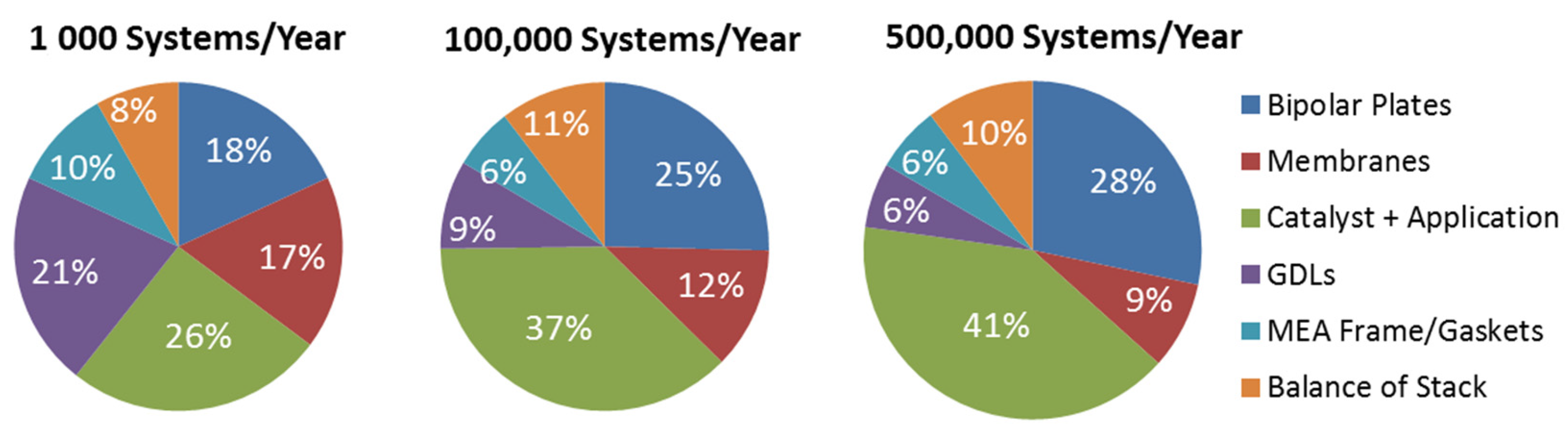
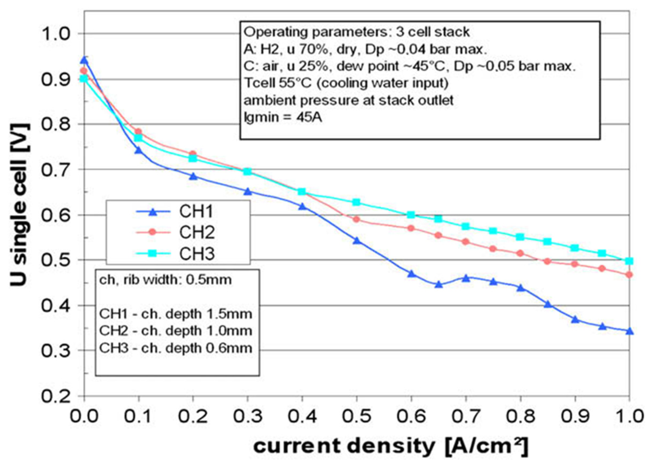
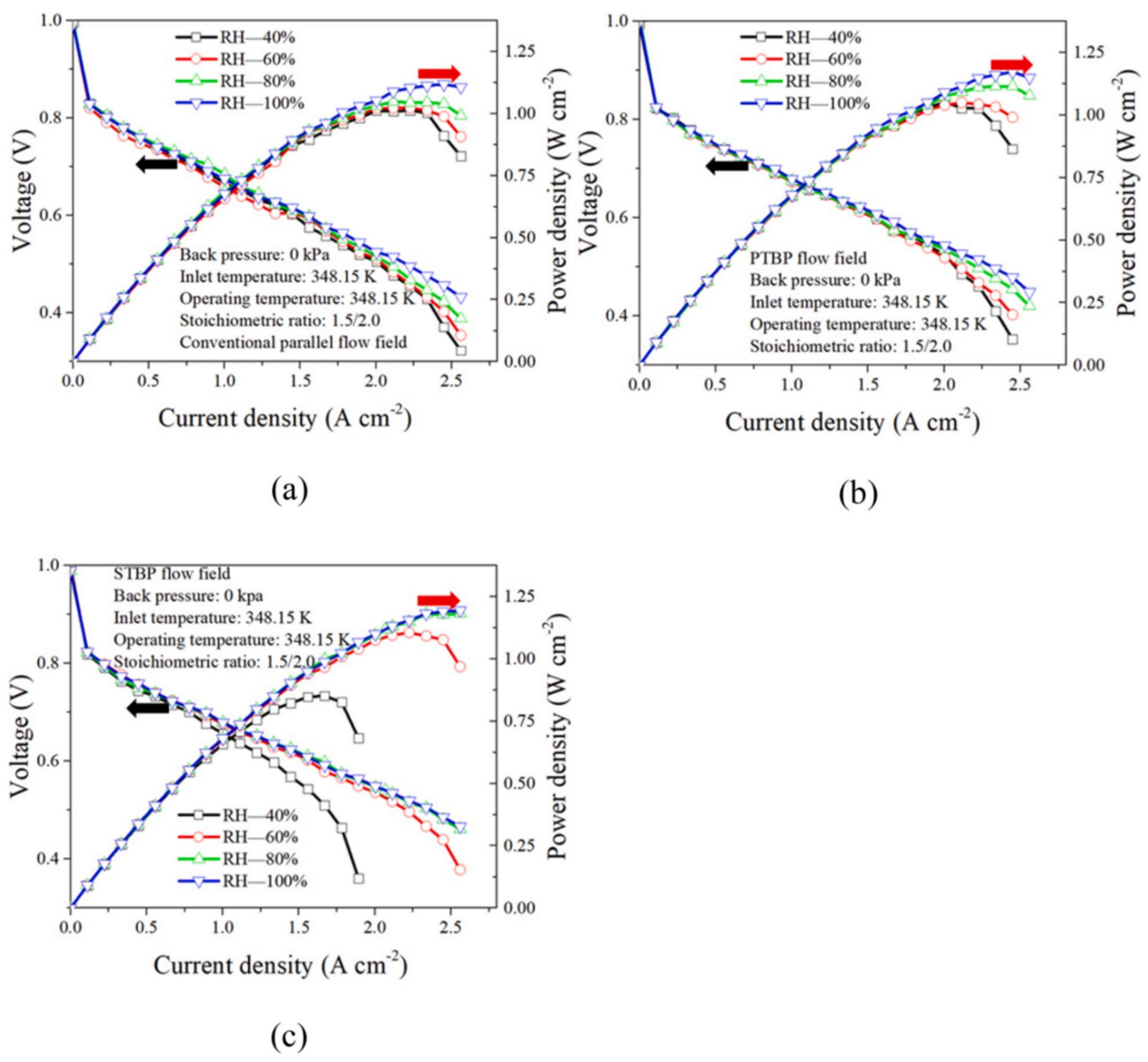
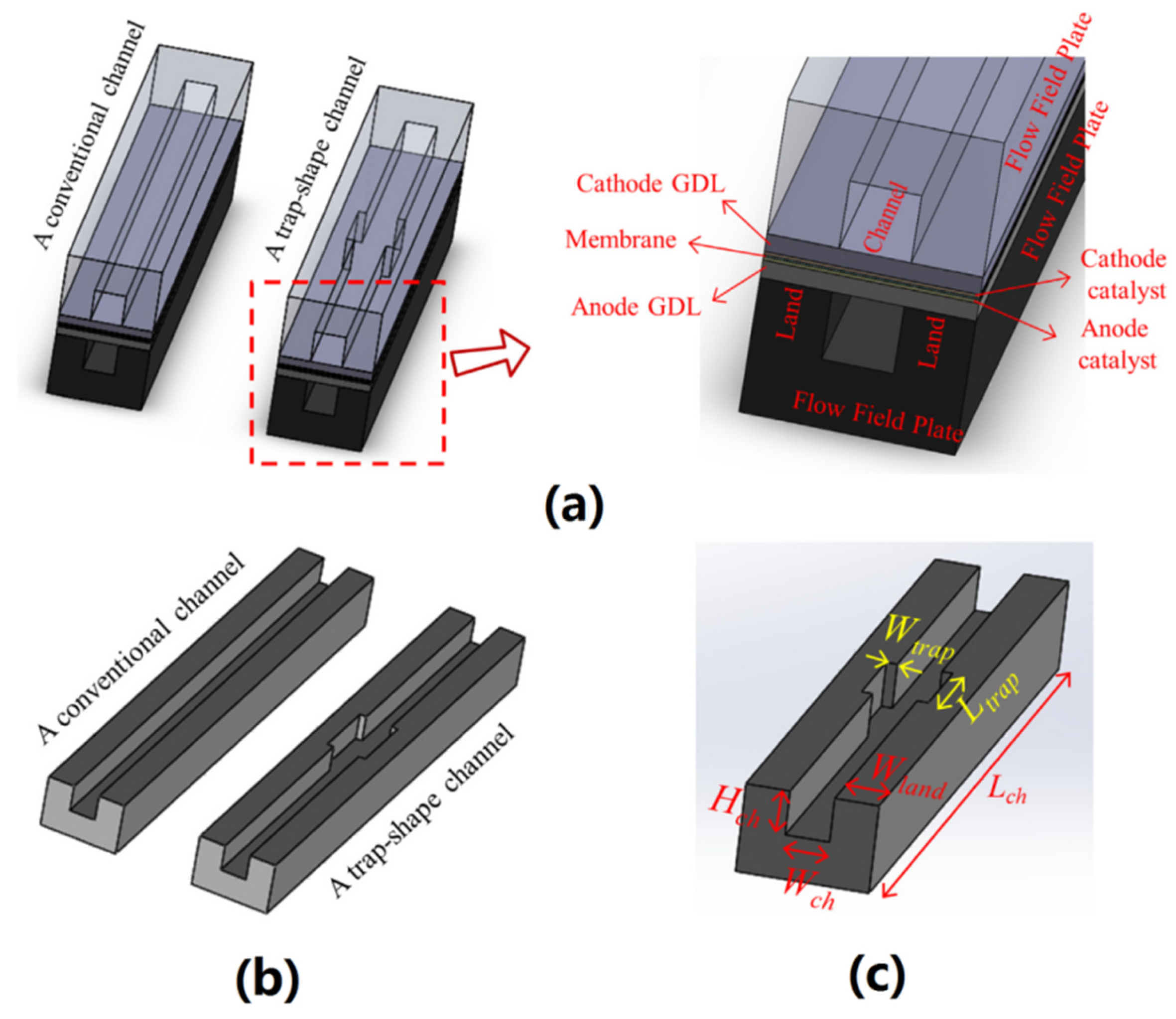
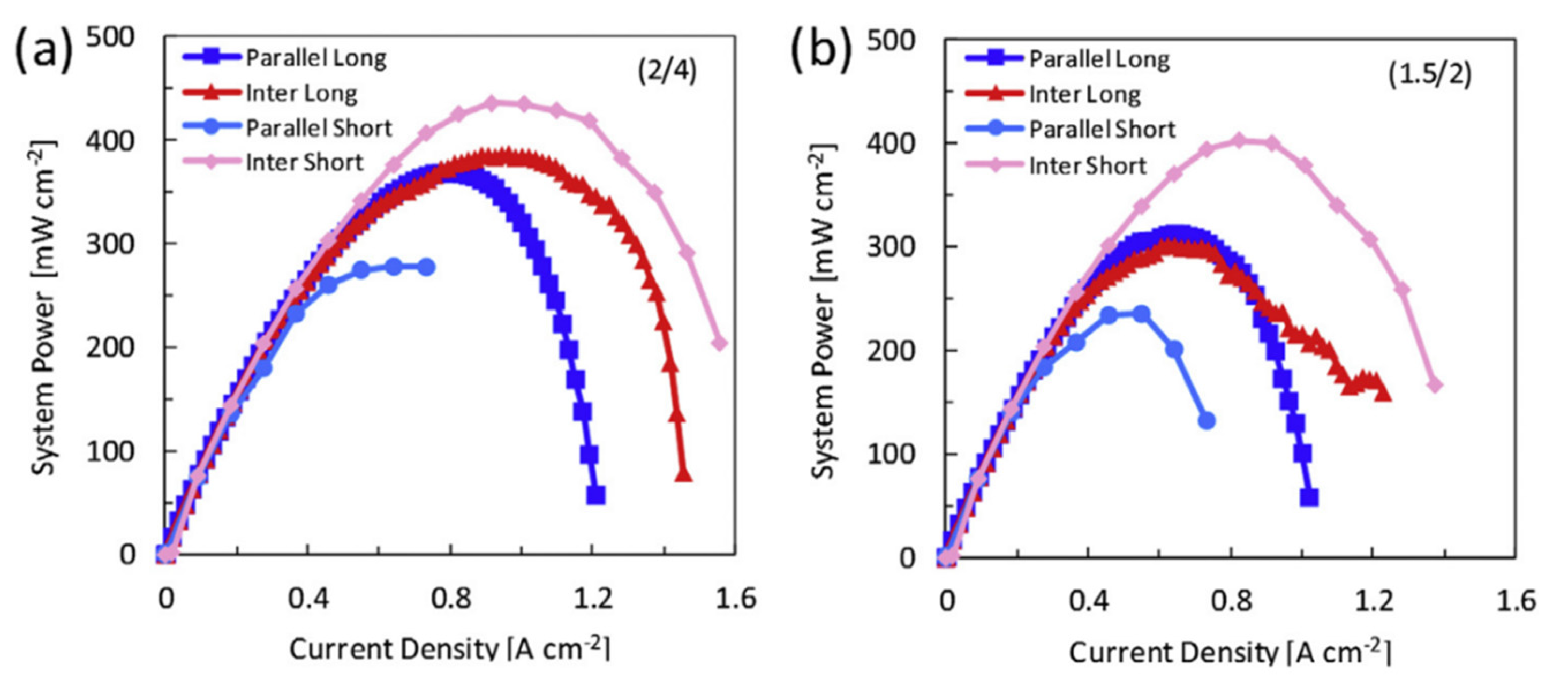
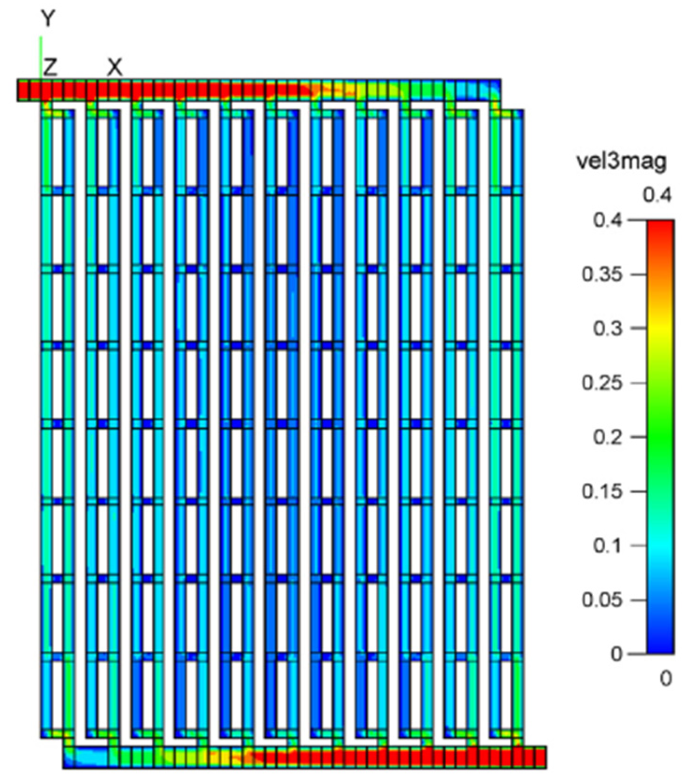
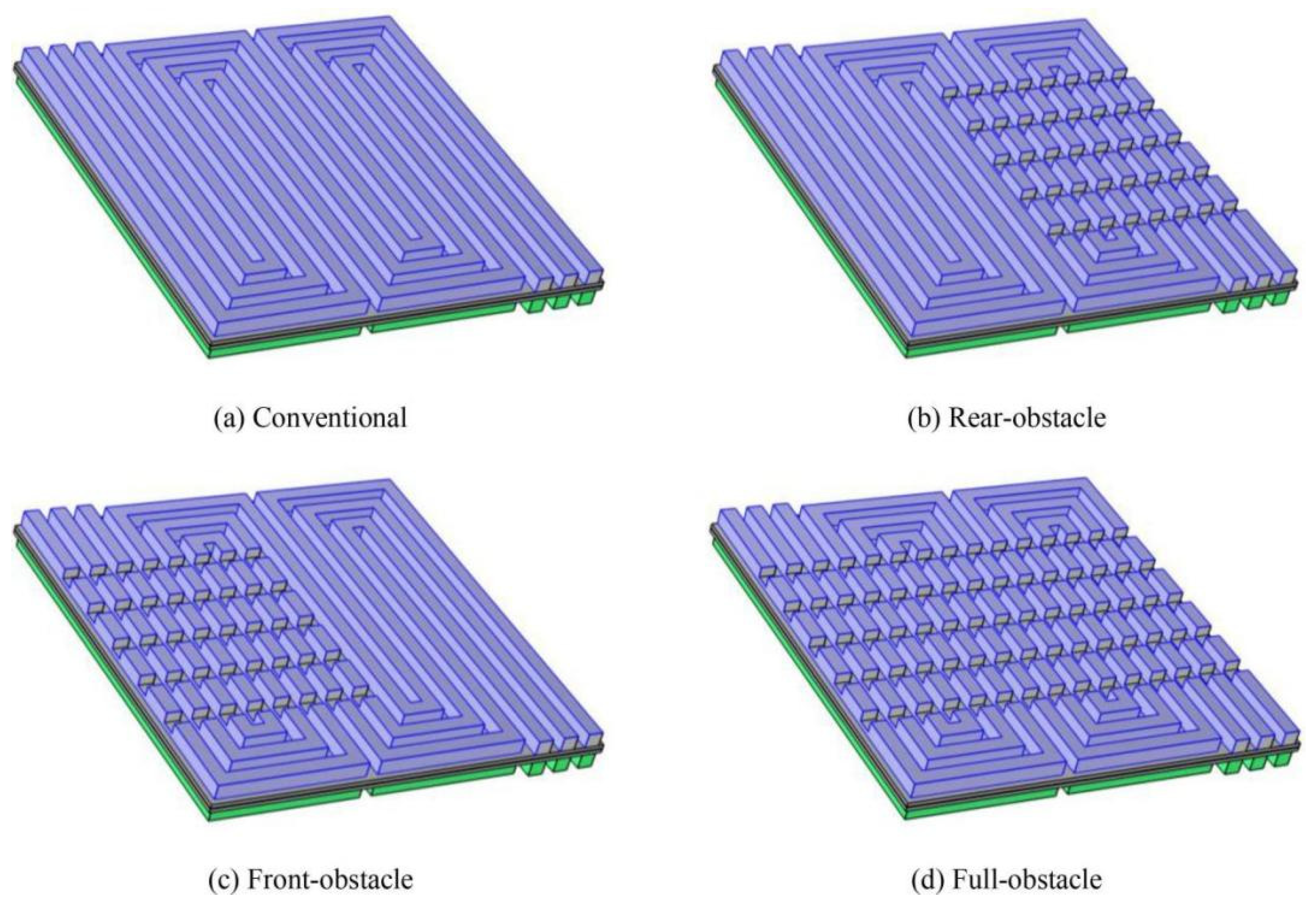
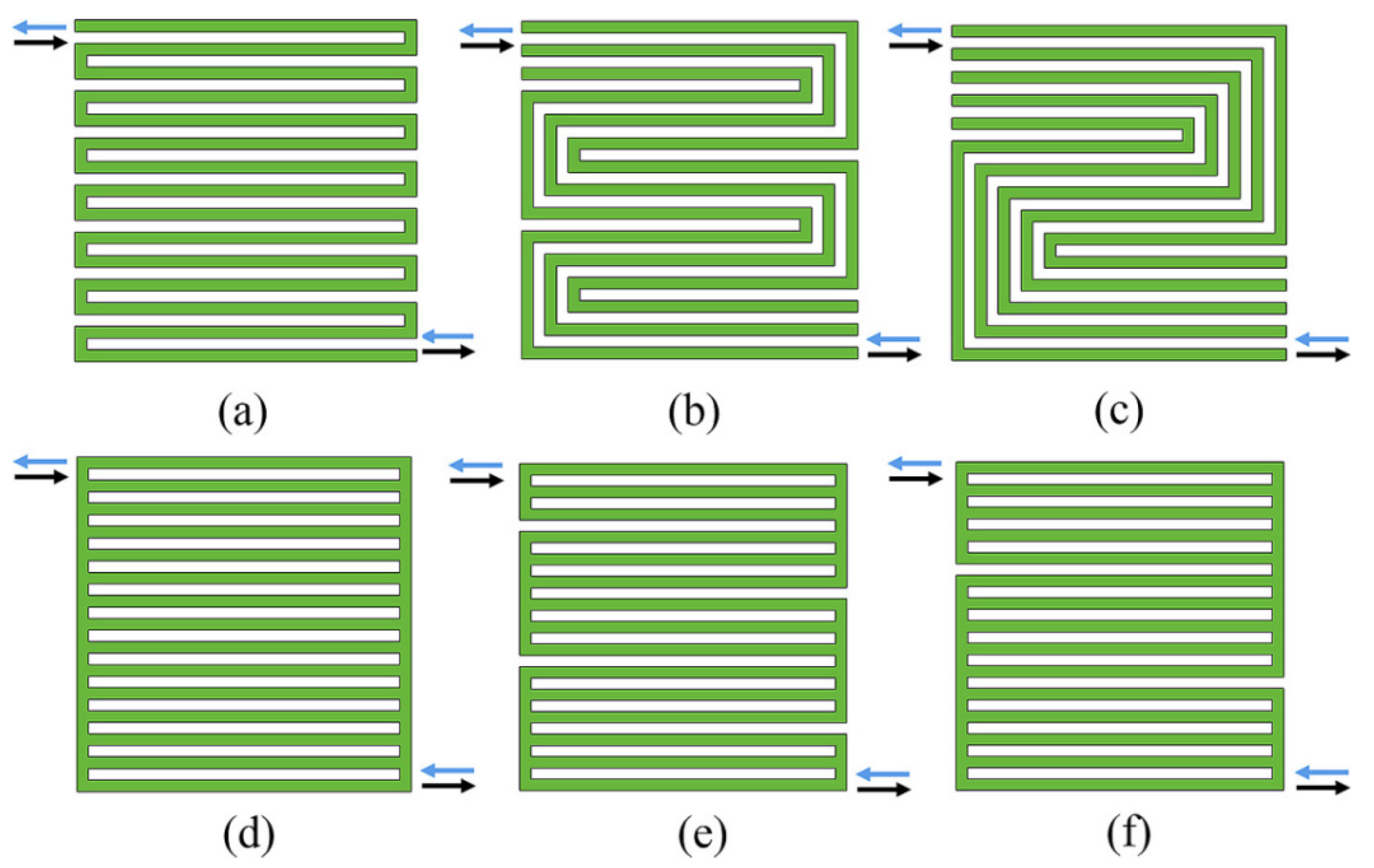
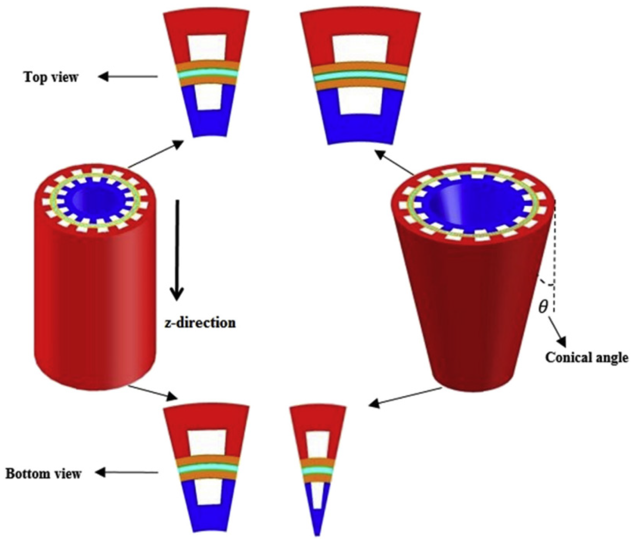
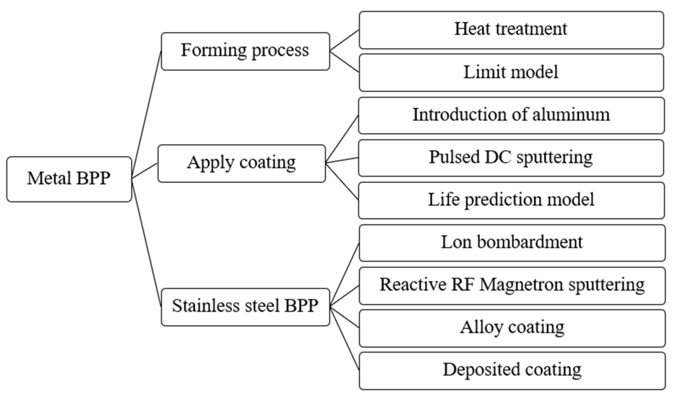
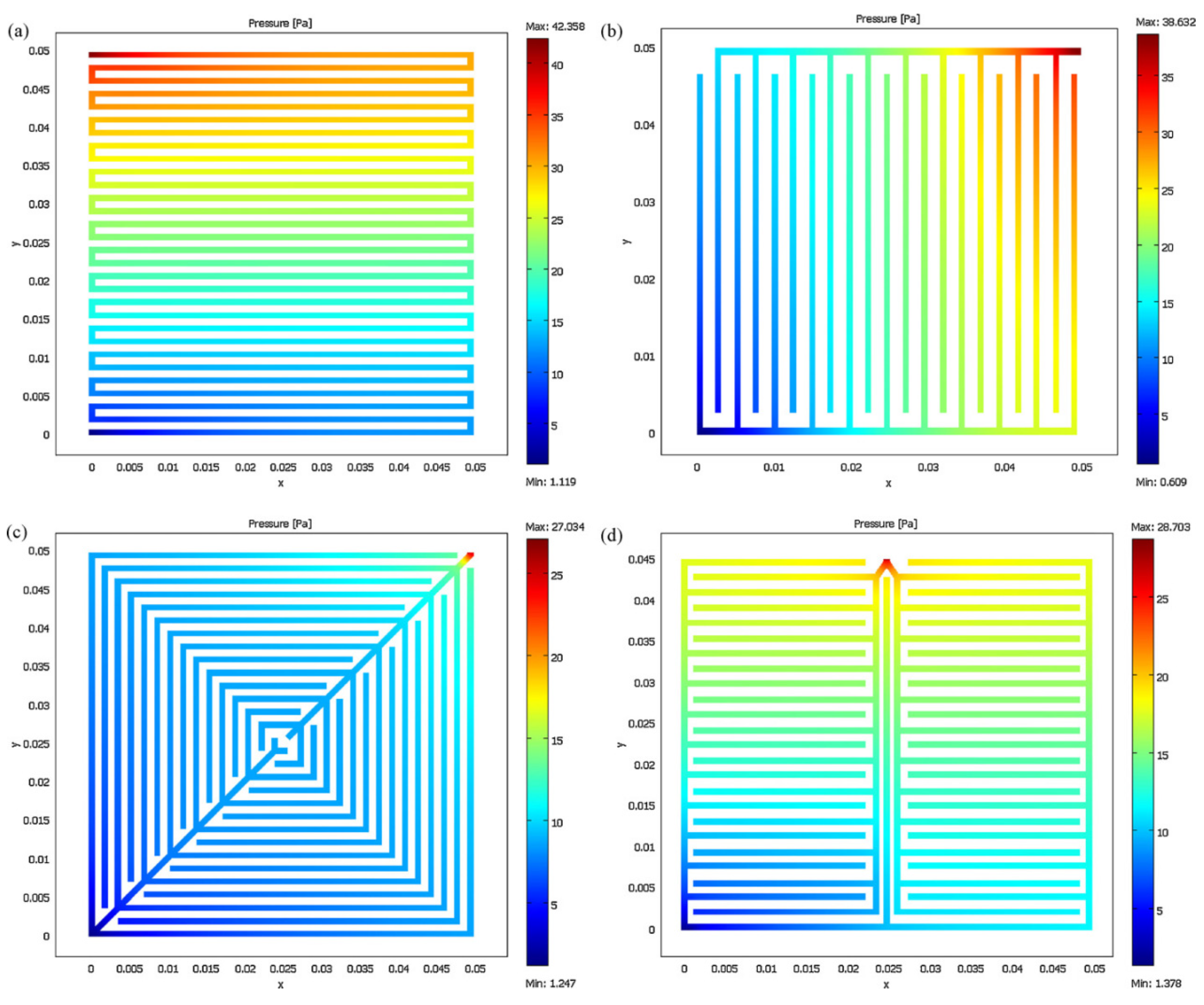
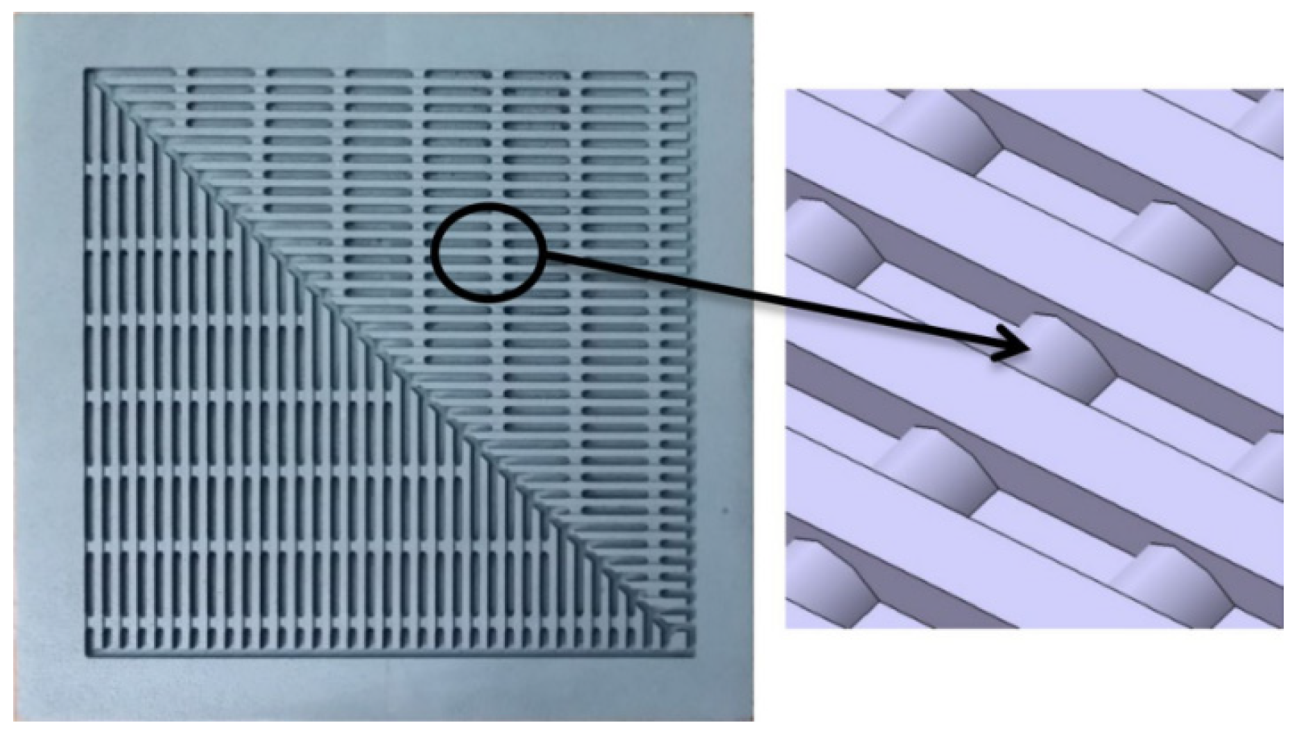
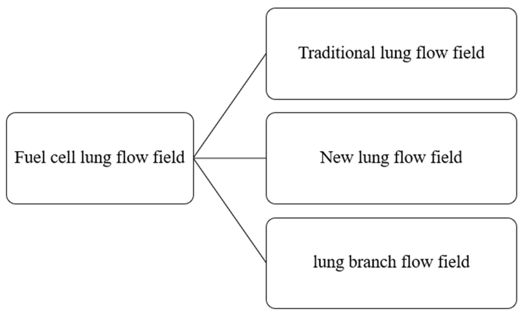
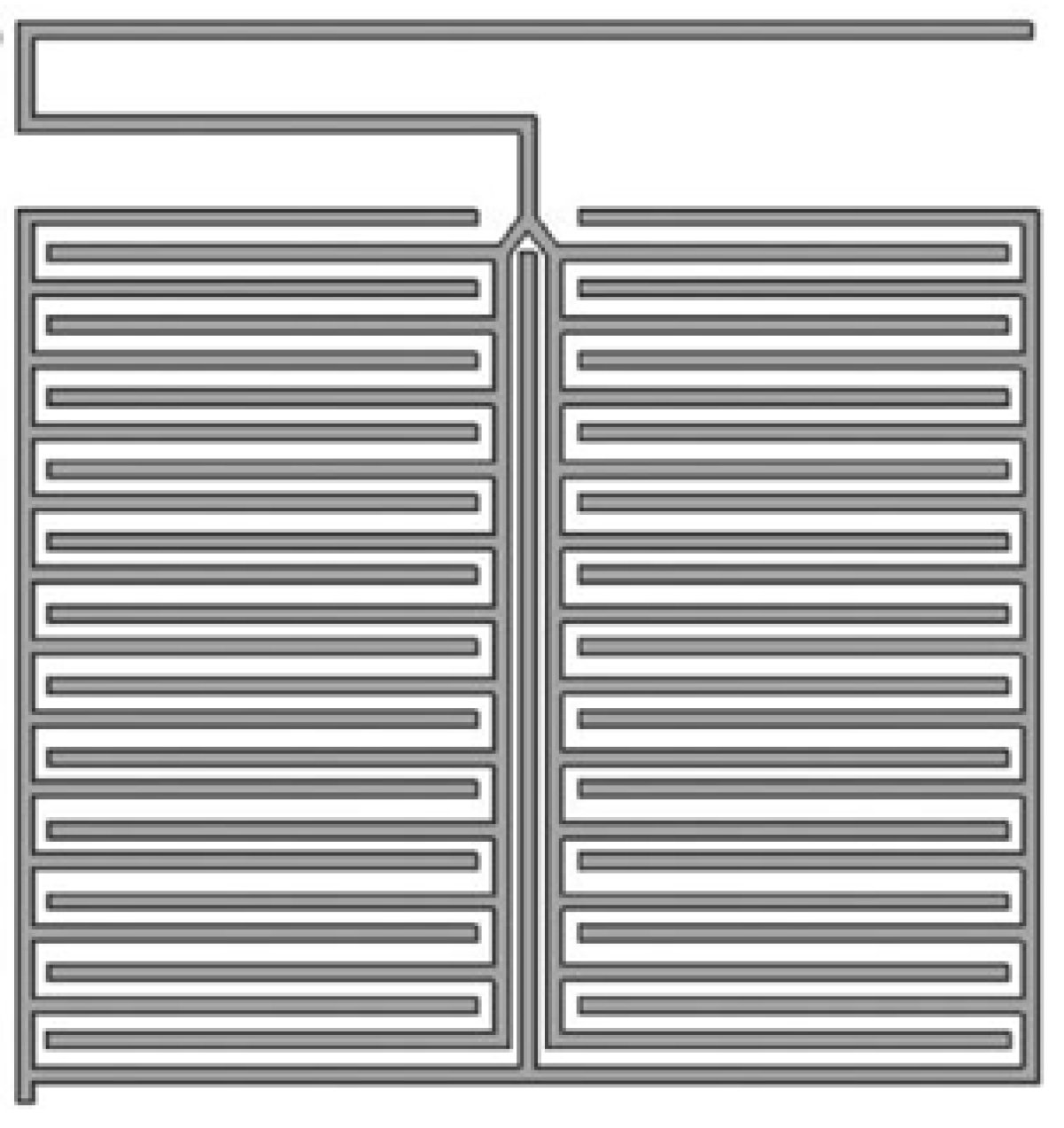
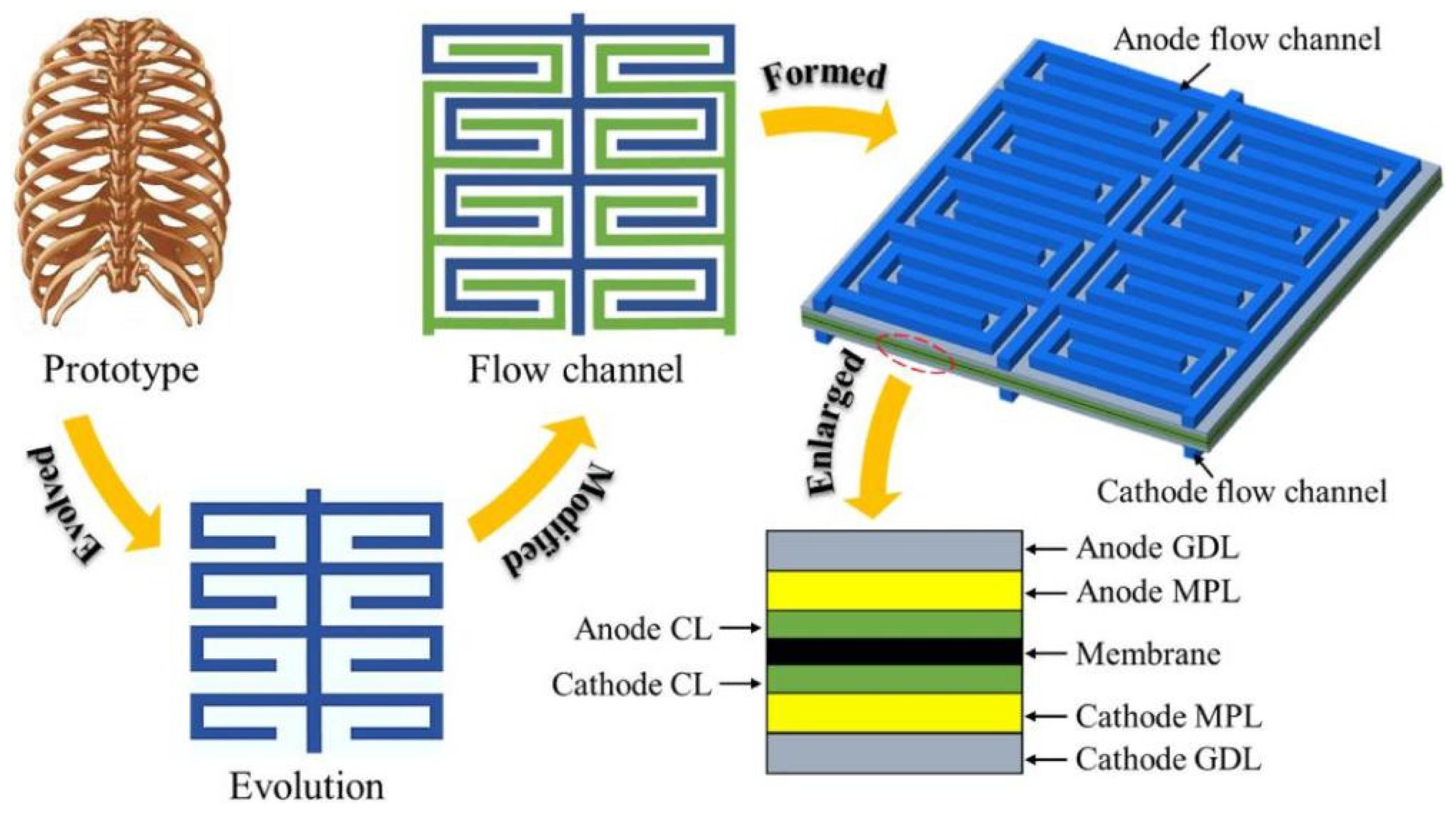
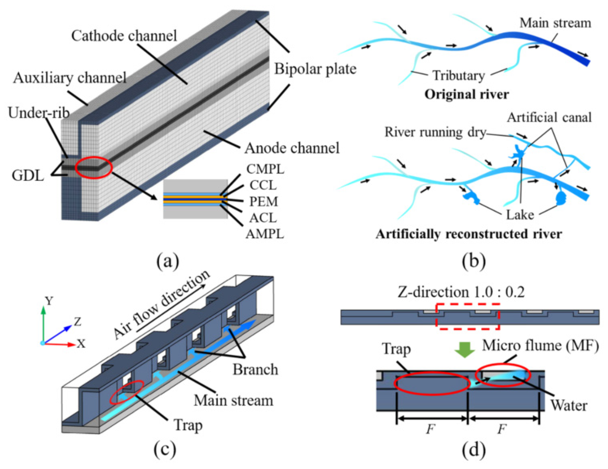