Article

Bi-Functional Non-Superconducting Saturated-Core Inductor for Single-Stage Grid-Tied PV Systems: Filter and Fault Current Limiter

Electrical and Control Engineering Department, College of Engineering and Technology, Arab Academy for Science and Technology (AAST), Alexandria 1029, Egypt
*
Author to whom correspondence should be addressed.
Energies 2023, 16(10), 4206; https://doi.org/10.3390/en16104206
Submission received: 11 April 2023 / Revised: 3 May 2023 / Accepted: 16 May 2023 / Published: 19 May 2023
(This article belongs to the Special Issue Advances in Carbon Capture and Storage and Renewable Energy Systems)

Abstract

:
Single-stage grid-interfaced PV topologies have challenges with high grid fault currents, despite being more efficient, simpler to implement, and less expensive than two-stage ones. In such systems, a single inverter is required to perform all grid-interface tasks. i.e., maximum power point tracking (MPPT), DC voltage stabilization, and grid current control. This necessitates a hardware-based fault current limitation solution rather than a software-based one to avoid adding to the inverter’s control complexity and to mitigate the implications of PV system tripping. Therefore, in this study, a dual-functional non-superconducting saturated-core inductor-based (SCI) reactor is proposed to be applied at the output of a single-stage PV inverter. It involves two operation modes: a grid pre-fault mode where it filters the line current, hence minimizing its THD, and a grid-fault mode where it acts as a fault current limiter (FCL). Controlling the DC saturation current flowing into its control winding terminals alters the core magnetization of the SCI to vary its impedance between a low value during normal utility operation and a maximal value during faults. Consequently, the system is protected against inverter failures or unnecessary circuit-breaker tripping, which preserves service continuity and reduces system losses. Moreover, compared to existing FCLs, the proposed topology is an appealing candidate in terms of cost, size, reliability, and harmonic filtering ability. The bi-functionality and usefulness of the proposed reactor are confirmed using simulation and experimental results.

1. Introduction

The current global energy crisis and environmental threats from fossil-fueled energy resources have motivated research toward sustainable renewable energy resources (RES) [1]. Solar irradiance is a sustainable and clean energy source that can be used to generate electricity using PV systems [2]. Nowadays, the integration of PV sources into the utility grid is considered a common practice in many countries to prompt PV system penetration, reduce operational costs, and improve economics [3,4].
However, for a consistent and successful PV-grid interface, several requirements should be fulfilled [4,5]. First, PV cells’ non-linearity and dependency on varying irradiance and temperature conditions should be overcome using an efficient MPPT technique to harvest the maximum available PV power [6]. Then, for the successful transfer of this power to the AC utility, robust DC/AC power conversion is needed. This mandates two control loops: DC-link voltage regulation and AC grid current control. The former guarantees energy balance at the DC link, while the latter is responsible for injecting sinusoidal grid current into the grid with minimal total harmonic distortion (THD) at unity power factor operation.
The previous tasks can be successfully achieved via different numbers of power conversion stages, commonly either two-stage or single-stage topologies [7]. In the former topology, two conversion stages are used, which involve a DC-DC converter for MPPT, voltage level boosting, and buffering purposes. This was followed by a DC/AC inverter stage for the PV-grid interface [8]. However, in the single-stage configuration, a single DC/AC converter is placed between the PV and utility to achieve all the previously discussed tasks, thus reducing the system footprint and increasing its overall efficiency [9].
However, the single-stage topology still has its limitations. First, the output PV voltage is the DC-link voltage of the single-stage inverter [10]. Hence, this PV voltage should be reasonably high for a successful interface. This requirement necessitates the use of multiple PV modules connected in series, forming a PV string, rather than relying on a single PV module. Another limitation in the single-stage topology is the absence of decoupling between the PV and the inverter DC-link, which will result in a direct reflection of the PV power oscillations on the grid current THD and vice versa. This requires a large DC-link capacitor at the inverter input and a convenient AC filtering inductor at its output [11]. Moreover, a single inverter is responsible for performing all functions of MPPT, DC voltage regulation, and grid current control, which complicates inverter control [12,13]. This implies a robust control system in addition to a reliable inverter, especially during grid abnormalities and faults. Otherwise, the system will entirely collapse since it relies solely on a single converter. Unfortunately, single-stage PV systems are susceptible to grid disturbances and exhibit delayed control dynamics following fault recovery [4]. As a result, it is critical to offer support for utilities in case of malfunction when connecting PV plants to the grid, particularly for single-stage systems.
Since solar inverters are designed to extract the maximum power available from solar panels to the network prior to fault, it is argued that during faulted conditions, solar inverters serve as a constant power source. Shortly after the occurrence of a fault, the fault current exhibits large spikes, and the peak value varies according to the voltage drop caused by the fault [14]. For this reason, grid-connected PV inverters use current-limiting strategies or devices to protect critical components and avoid damage to PV inverter components. Based on the results obtained from commercial PV inverters, up to 1.4 p.u. is commonly indicated [15]. Accordingly, if any of the currents exceed this threshold, the inverter is disconnected from the grid via overcurrent protection schemes, which affect service-to-customer reliability and efficiency after fault clearance [16]. Another factor that must not be neglected is the relatively long time it takes for a grid-connected PV system to reach its maximum power output after grid restoration [17]. The excessive control action accumulated in the inverter controller’s integral part must be compensated for by an input error in the opposite direction. As a result, the DC-link voltage falls below the reference value, which may cause the inverter to lose control and disconnect due to the significant decrease in the DC-link voltage [16]. Thus, with post-fault clearance, the likelihood of system instability increases.
Consequently, fault current limitation solutions are widely recognized to counteract all the aforementioned problems [18]. Commonly, they are software-based (control) solutions [19,20] or hardware-based (equipment) solutions [21,22,23]. The latter is more applicable for single-stage grid-tied RES systems, not to add to the control complexity of the applied inverter, which is already responsible for all the MPPT and grid-integration functions alone. Equipment-based measures need to be enabled/triggered during faults and are disabled in normal conditions. They have a wide variety of options, such as high-impedance transformers, high-voltage current limiter fuses, and fault current limiters (FCL) [21,22,23]. FCLs are gaining attention in power systems applications with different existing topologies such as FACTS devices, solid-state switch-based FCLs, superconducting FCLs, hybrid FCLs, and non-superconducting FCLs.
Superconducting FCLs are based on the superconductivity characteristic of materials that tend to lose their electrical resistance at certain temperatures, current density, and magnetic fields. These devices can provide a self-acting action during over-current faults, thus serving as a lossless current-limiting variable impedance [24]. On the other hand, solid-state switch-based FCLs dynamically insert an additional impedance into the line when a fault event is detected via power-electronic equipment to handle short-circuit fault consequences. For this reason, they are lower in cost compared to superconducting FCLs, have a more flexible structure, and have a short response time [25]. The hybrid FCLs provide a combination of superconducting FCLs and solid-state switch-based ones. As a result, these FCLs enjoy the benefits of both technologies, with good response time and current-limiting performance. Alternatively, FACTs devices are static power-electronic equipment deployed in transmission networks to improve power transfer capabilities, enhance network stability, and limit fault current through series and/or shunt compensation. Compared to other FCL topologies, non-superconducting FCLs are considered an attractive alternative in terms of cost, need for maintenance, and weight since no cooling systems or switching devices are involved. This makes them a good option in renewable energy systems with the minimum harmonic generation, a fast response time (during and after fault clearance), and less control complexity [21,23]. Nevertheless, saturated-core devices create low insertion impedance as well as high transient impedance during fault occurrence by changing the permeability of the core material between saturated and unsaturated states. They are feasible for implementation in high-voltage and high-power applications, with fast-acting dynamics and short recovery times [26].
In this paper, the merits of non-superconducting FCLs and those of saturated-core devices are combined, and a dual-functional non-superconducting saturated-core inductor (SCI) is proposed to replace the existing filtering inductor between the PV inverter output and the utility grid. The proposed SCI serves two different functions depending on the utility’s operation mode. First, during grid normal operation, a DC saturation current is injected into its control coil terminals, thus forcing its core into the saturation region to minimize its impedance and just act as a filtering reactor. Oppositely, during grid faults, when high line fault currents are exhibited, the SCI is forced out of saturation, thus maximizing the reactor impedance to mitigate grid current increases. The proposed SCI mainly contributes as follows:
  • Its FCL functionality is quite effective, especially in single-stage grid-tied inverters, since it is a hardware/equipment-based solution rather than a software-based one. Thus, it does not add to the control complexity of the system’s single inverter.
  • Consequently, it supports the penetration of single-staged PV systems in the utility grid, which feature less size, cost, and losses compared to two-staged ones.
  • It replaces the already existing AC line smoothing inductor, thus avoiding the use of dedicated FCL equipment for short-circuit current limitation.
  • Compared to existing FCLs, the non-superconducting saturated-core topology gives the best compromise regarding low cost, size, control complexity, high reliability, and harmonic filtering capability under normal conditions.
  • Due to its bi-functionality, it has a number of positive impacts on the grid, as follows:
    • Minimal grid current THD at grid normality as it acts as a current smoothing filter.
    • Limited grid fault currents to 1.4 times their nominal value, thus preventing inverter breakdown, enhancing its control robustness, and protecting utility equipment from overheating and possible failure.
    • Reduced unnecessary tripping of utility protective devices, thus supporting service continuity, reducing losses, and enhancing the entire system’s efficiency and reliability.
Finally, the effectiveness of the proposed SCI in single-stage PV systems, during different grid modes, is verified using simulation results. For further validation, an experimental prototype is implemented to confirm its real-time performance.

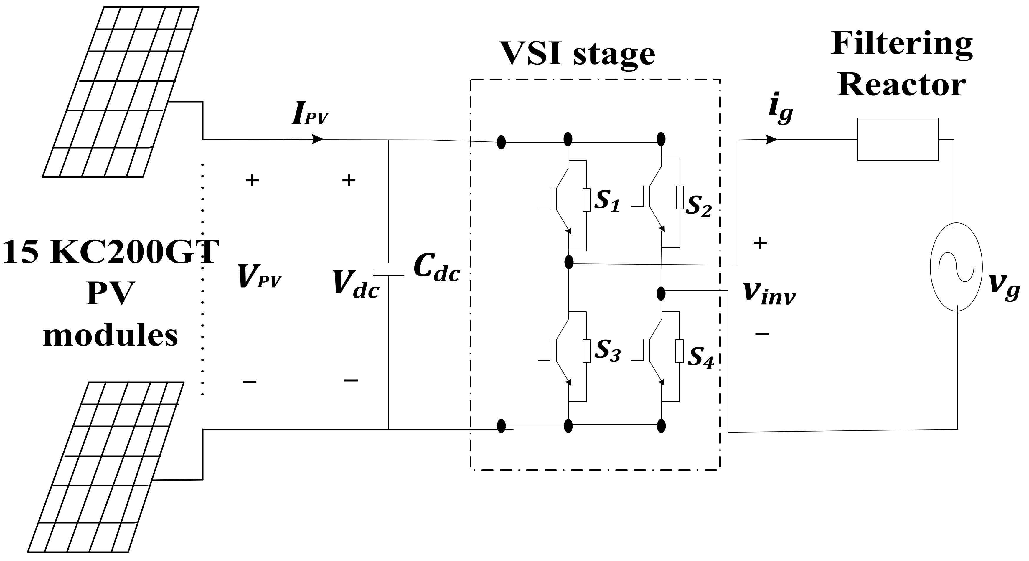
2. System under Investigation

For low-power (<10 kW) applications, PVs are usually interfaced with a 110/220 V AC grid through a single-phase voltage-source inverter (VSI). The single-stage topology normally applies a single inverter to carry out all the required interface tasks: MPPT, outer DC-link voltage control loop, and inner grid current control loop [12,13].

2.1. System Design

A 3 kW, 220 V, 50 Hz single-phase PV grid-tied system is considered with the schematic diagram shown in Figure 1. The PV source is a string configuration of fifteen KC200GT PV modules connected in series to meet the grid voltage level. This PV source is interfaced with the grid through a single-stage, current-controlled VSI responsible for all the control processes required for this interface. Table 1 gives the system parameters computed below.

2.1.1. Decoupling Capacitor Selection

In single-phase grids with unity power factor, i.e., grid current ( i g ) is in phase with grid voltage ( v g ), grid power ( P g ) pulsates at double the line frequency ( P g cos 2 ω t ) [27]. Hence, for single-staged PV systems tied to single-phase grids, the VSI DC-link capacitor ( C d c ) is the main buffer to limit the propagation of these power pulsations to the PV side. Hence, it must be properly sized to limit DC-link voltage ripple, which is mirrored on the PV voltage ( V P V ) and power ( P P V ), to a desired level. This, in turn, prevents DC-bus overvoltage and minimizes PV power oscillations, the effect of which is reflected in the grid current. C d c that limits DC-voltage ripple Δ v d c to a desired value is given by [27,28]:
C d c = P g 2 ω V d c Δ v d c
where ω is the grid line angular frequency in rad/sec and V d c is the inverter DC-link voltage.

2.1.2. Full Bridge Voltage Source Inverter (VSI)

The applied single-stage PV inverter is a full-bridge single-phase current-controlled VSI operating with sinusoidal pulse width modulation (SPWM) featuring a switching frequency ( f s w i t c h i n g ) of 15 kHz. For high switching frequency and near-unity power factor operation, the inverter output voltage is almost equal to the grid voltage, and the modulation index amplitude ( m a ) is given by [29]:
m a = V g ^ V d c      
where V g ^ is the grid voltage peak.
For single-phase inverters, the DC-link voltage level is set to satisfy m a 1   to achieve acceptable total harmonic distortion in the grid current (THDi). Hence, the number of series modules in the PV string is chosen to satisfy this level since in single-stage systems, the inverter V d c is equal to the PV voltages of all modules summed together.

2.1.3. Filtering Reactor

Conventionally, a filter inductor ( L a c ) is placed between the inverter AC output and the grid current to filter the grid, thus L a c is calculated from Equation (3) so as to limit the magnitude of the switching harmonics in grid current as follows [30]:
Δ I g = V d c 2 f s w i t c h i n g L a c 1 2 3 1 2 m a 2 8 3 π m a 3 + 3 8 m a 4
where Δ I g is the grid current rms value and is calculated from Equation (4) [30]:
T H D i = Δ I g I g 1 × 100 T H D i   r e q u i r e d
where I g 1 is the rms value of the grid current fundamental frequency component.
However, to make use of the mandatory presence of a filtering reactor between the inverter output and the grid, L a c is replaced by a bi-functional non-superconducting saturated-core inductor (SCI) as proposed by this paper. Additionally, its grid current filtering integrated feature has a fault current limiting capability to limit grid current rises during grid faults. The design and operation of the proposed SCI are explained in Section 3.

2.2. System Control

The PV string is interfaced with the utility through a single-stage VSI responsible for all the control processes required for this interface: MPPT, DC voltage control, and grid current control. System control is shown in Figure 2 and explained as follows:

2.2.1. MPPT

In order to harvest maximum PV power from the employed PV string under varying irradiance and temperature conditions, a simple and efficient MPPT algorithm is mandatory. Hence, the variable-step Inc. conductance algorithm proposed in [31] is applied due to its low cost, simple implementation, and reliable performance. This algorithm determines the reference MPP PV voltage at which the PV string operates at its maximum power relative to the surrounding environmental conditions.
The reference produced PV voltage is considered the reference of the inverter DC-link voltage, at which it should be regulated to maintain the energy balance at the inverter DC-link and guarantee power flow from the PV source to the utility. Thus, for a successful PV-grid interface, DC-link voltage regulation as well as grid coupling at unity power factor are achieved using two control loops: the outer DC-link voltage control loop and the inner grid current control loop.

2.2.2. Inner Grid Current Control Loop

The block diagram of the inverter’s inner grid current control loop is shown in Figure 3. In this loop, the inverter must output a sinusoidal grid current with acceptable THD and a close-to-unity power factor to achieve the required PV-grid integration. Thus, a sinusoidal unit vector obtained from a phase-locked loop (PLL) synchronized with the grid voltage is multiplied by the output of the DC-link voltage controller, which represents the reference grid current amplitude. The inner current loop controller then forces the grid current to coincide with this sinusoidal reference.
When controlling sinusoidal signals, PR controllers perform better than conventional PI ones [32]. In contrast to conventional PI controllers, the former can eliminate steady-state errors in the current’s magnitude and phase angle without the use of voltage feedforward. Hence, for grid control, an ideal PR is applied with a gain given by Equation (5) [12,32]
G P R s = K P r + K I r s s 2 + ω r 2  
where K P r is the proportional part gain, K I r is the resonant part gain, and ω r is the resonant frequency of the controller, which is chosen as the grid line angular frequency to eliminate grid current harmonics.
The converter PWM block can be represented by a simple gain as given by Equation (6) and shown in Figure 2 since a high inverter switching frequency is applied [27,33]
K P W M v = V d c V t r i ^  
where V t r i ^ is the amplitude of the triangular carrier signal

2.2.3. Outer DC-Link Voltage Control Loop

The block diagram of the inverter’s outer voltage control loop is shown in Figure 4. In this loop, the inverter DC-link voltage is regulated to a reference value, which is the PV MPP voltage, to guarantee PV operation at MPP and maintain energy balance at the DC-link. This loop outputs I g r e f ^ , which represents the reference grid current active component denoting the power available at the inverter DC side that should be injected into the grid [27,33]. A proportional-integral (PI) controller is employed in this loop as shown in Equation (7), where K P i and K I i are controller proportional and integral gains, respectively.
G P I s = K P i + K I i s  
Featuring unity feedback and a few kHz of bandwidth, the inner grid current loop can be represented by [27,33]: a unity gain at the low-frequency range applied for the DC-link voltage loop. Moreover, the relationship between the average DC-link voltage and fundamental grid current variations can be computed using Equation (8) depending on the average power balance equation, neglecting converter losses [27,33]:
V d c s I g ^ s = V g ^ 2 s C d c V d c
where I g ^ is the injected grid current amplitude.

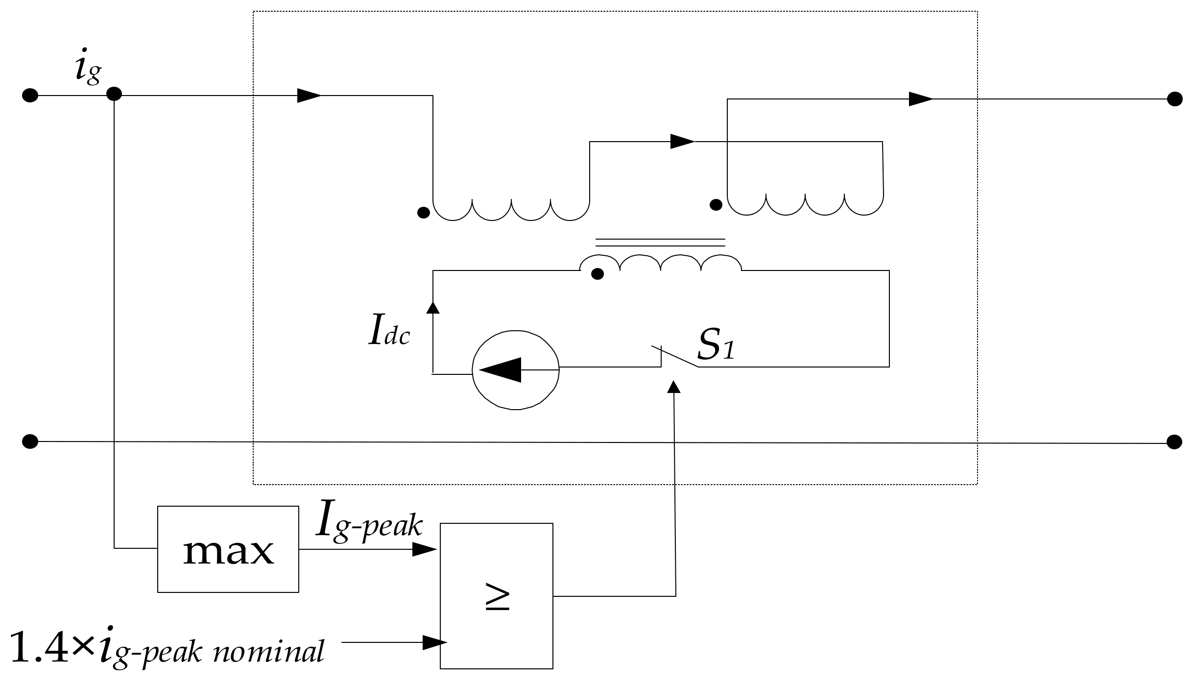
3. Operation and Design of the Proposed SCI

Based on magnetically controlled reactors, the proposed SCI utilizes the nonlinear variation of its core material to restrict the short-circuit current of the system.

3.1. Proposed SCI Operation

Saturated-core FCLs (SCFCLs) typically consist of an iron core wrapped around two counter-connected main AC windings and a DC control winding. The two AC coils are linked in series with the system, while the DC winding input is controlled so that the produced DC magnetomotive force (MMF) causes the core to reach a state of deep saturation.
Figure 5 shows the connection diagram of the proposed SCI. Under normal working conditions (no-fault), the AC MMF magnitude is not adequate to drive the core into saturation, so the DC bias current is set to make the core in a deep saturated state. This is achieved by injecting DC current, I D C S C I into the SCI. At this point, the SCI acts as a filter inductor with very low impedance, i.e., a low voltage drop across its AC windings.
If a fault incidence occurs and the magnitude of the grid peak current, I g p e a k exceeds 1.4 times its nominal value ( I g p e a k   n o m i n a l ) , the SCI shifts operation and acts as a FCL. At this point, the fault current amplitude increases, generating an AC MMF that is large enough to oppose the DC bias MMF and lead the core out of saturation. To guarantee the latter and maintain robust performance, a switch is triggered in this case to disconnect the employed current source. Thus I D C S C I   is set to zero. Hereby, the SCI presents a large impedance, which serves to restrict the short-circuit current [26].

3.2. Proposed SCI Design

The design procedure of the SCI is demonstrated in the following section, as shown in the flowchart in Figure 6.

3.2.1. Core Design

Since the SCI will operate at a low power supply frequency, silicon iron laminations are suitable due to their low cost and high saturation flux density [34]. These types of cores can be manufactured in a variety of geometries, such as the EI configuration used in this study. For large reactors, stacked laminations of core materials are typically utilized for managing a significant amount of power to avoid excessive costs associated with high-quality core materials.
To determine the size of EI laminations, it is first required to determine the SCI area product, A p , which is given by Equation (9) [35]:
A p = S × 10 4 k f k u k j f B m
where S is the apparent power rating of the SCI, k f is the waveform coefficient of the sinusoidal input current, k u is the window utilization coefficient, which represents the amount of copper appearing in the window area. k j is a constant for temperature rise in the SCI core and is usually related to core configuration, f is the supply frequency, and and B m is the maximum flux density of the core material.
Using EI lamination design tables and values obtained in Equation (9), core area, A c and window area, W a are determined accordingly.

3.2.2. Main and Control Winding Design

This step involves determining the required number of turns for both main and DC control windings, cables, and wiring selection according to current density capabilities, as well as window areas for each group of windings [34].
The main AC winding number of turns, N m a i n is determined by Equation (10)
N m a i n = V × 10 4 k f A c f B m
where V is the main winding voltage. The current rating of the main winding, I m a i n , can be calculated according to Equation (11) such that:
I m a i n = S V
Accordingly, the current density of the main winding, J m a i n , the bare wire area, A m a i n w g b a r e , and the main winding window area, W a m a i n can be determined as follows:
J m a i n = k j A P 0.125
A m a i n w g b a r e = I m a i n J m a i n
Using AWG wiring tables, the main winding wire area, A m a i n w g can be determined.
W a m a i n = A m a i n w g b a r e × N m a i n k u
Assuming that the main winding will occupy 70% of the space and the control (DC) winding will occupy the rest. Using AWG tables, similarly, the number of turns of DC control winding, N D C , control winding current, I c o n t r o l , control winding bare area, A c o n t r o l w g b a r e , and control winding area, A c o n t r o l w g can be calculated.

3.2.3. Main and Control Winding Resistance Determination

Main and control winding resistances, R m a i n and R c o n t r o l , can be calculated as follows [35]:
R m a i n = M L T × N m a i n × m i c r o o h m c m
R c o n t r o l = M L T × N c × m i c r o o h m c m
Such that M L T , is the mean length turn for both windings and is dependent on the dimensional data of EI laminations, and the m i c r o o h m c m values are obtained from wiring tables.

3.2.4. Winding and Core Loss Calculation

Total copper losses, P c u t o t a l   for both main and control windings, P m a i n and P c o n t r o l can be calculated as follows:
P c u t o t a l = P m a i n + P c o n t r o l
Such that,
P m a i n = I m a i n 2 R m a i n  
P c o n t r o l = I c o n t r o l 2 R c o n t r o l  
The core loss calculation, P c , can be expressed by Equation (20):
P c = k B m β f α  
where α and β are coefficients that depend on material properties.
According to the previous design procedure, the parameters of the proposed SCI, to be applied in the considered PV system demonstrated in Section 2, are selected and listed in Table 2.

4. Simulation Results Analysis

In order to verify the functionality of the proposed SCI, the considered 3 kW, 220 V, 50 Hz single-phase, single-stage grid-tied PV system, which has been demonstrated in Section 2, is tested using MATLAB/Simulink at a temperature of 25 °C and irradiance of 1000 W/m2. Simulation results have been carried out considering three grid conditions: (i) normal operation (t = 0–3 s); (ii) fault condition ( v g reduced to 0.5 p.u. during the period; t = 3–6 s); and (iii) severe fault condition ( v g reduced to 0 p.u. during the period; t = 6–9 s). The considered system, under these scenarios, is tested twice. First, when an AC filtering inductor, L a c of 5 mH, is used at the inverter AC output. Then, when replacing L a c with the proposed SCI, the simulation results for both cases are shown in Figure 7 and Figure 8, along with the system performance parameters provided in Table 3.
Normally, during the interval preceding the fault (0   t 3 ) , the grid voltage is maintained at 1 p.u., and the conventional L a c acts as a grid-filtering inductor. Similarly, the proposed SCI acts as a smoothing inductor since it is driven into a saturation state with the help of the DC control winding current, I D C S C I , as long as the peak nominal grid current, I g p e a k is within safe limits (≤1.4 I g p e a k   n o m i n a l   o f   20 A). During the normal condition time period, it is clear that L a c and the proposed SCI provide nearly similar results. In both cases, the maximum PV power of 3 kW is successfully tracked as per Figure 7a and Figure 8a, the DC-link voltage is accurately regulated at about   400 V as per Figure 7b and Figure 8b, and the sinusoidal grid current, i g at unity power factor, is injected into the grid as indicated by Figure 7c,d and Figure 8c,d. Moreover, minimal THD is achieved, corresponding to 2.41% and 3.55%, when using the conventional L a c and the proposed SCI, respectively, as per Figure 7e and Figure 8e.
During the first fault scenario (3   t 6 ) , a three-phase symmetrical short-circuit is applied to the downstream network at a grid voltage, v g of 0.5 p.u. At this point, the fault current is expected to flow in the grid, resulting in peak grid current, I g p e a k exceeding 1.4 times the nominal peak current of 20 A. Despite the fact that the PV power and DC-link voltages, P P V and V D C are maintained at 3 kW and 400 V, respectively, when using L a c , the grid current increase cannot be mitigated by the conventional AC inductor, as shown in Figure 7c, which cannot be tolerated. Comparatively, the proposed SCI successfully managed to limit the grid current, i g to a pre-fault value, as shown in Figure 8c. The SCI is driven out of saturation state and acts as a FCL with high impedance, and consequently, minimal active power is harvested and injected into the grid.
During the scenario of an extreme fault condition (6   t 9 ) , the grid voltage, v g suddenly drops to 0 p.u. Using the conventional L a c , the projected grid current value, i g , keeps increasing and exceeds the permissible inverter limits as per Figure 7c; thus, forced inverter tripping is anticipated. Additionally, the DC link voltage, V D C , is not stabilized as shown in Figure 7b, leading to disrupted inverter operation. On the contrary, the superiority of the proposed SCI and its blocking capability have been proven, as shown in Figure 8c. Interrupting the DC saturation current, I D C S C I flowing in its DC control winding forces its core outside the saturation region, and a large impedance is acquired. Consequently, the SCI was able to successfully limit the grid current to less than 1.4 times the nominal value, thus preventing inverter tripping. PV operation is restricted to V D C = 490 V, which is almost the PV open-circuit voltage, thus minimizing the power harvested from PV to a level that is just adequate to be dissipated in system resistances. There is no active power to be injected into the grid in this case since the utility features zero grid voltage; thus, the fault grid current is limited and the grid-tied inverter is protected.
Table 3 summarizes the simulation results of the three studied scenarios. It is evidenced from the first scenario that during grid normality, the proposed SCI filtering capability is proven where minimal grid current harmonics are achieved. During the other two fault scenarios, the proposed SCI FCL capability is verified to have successfully limited the grid fault current peak value, I g p e a k , below 1.4 p.u. In addition, for all scenarios, stable operation is assured for the DC-link voltage, V D C , and PV power, P P V , when applying the proposed SCI.

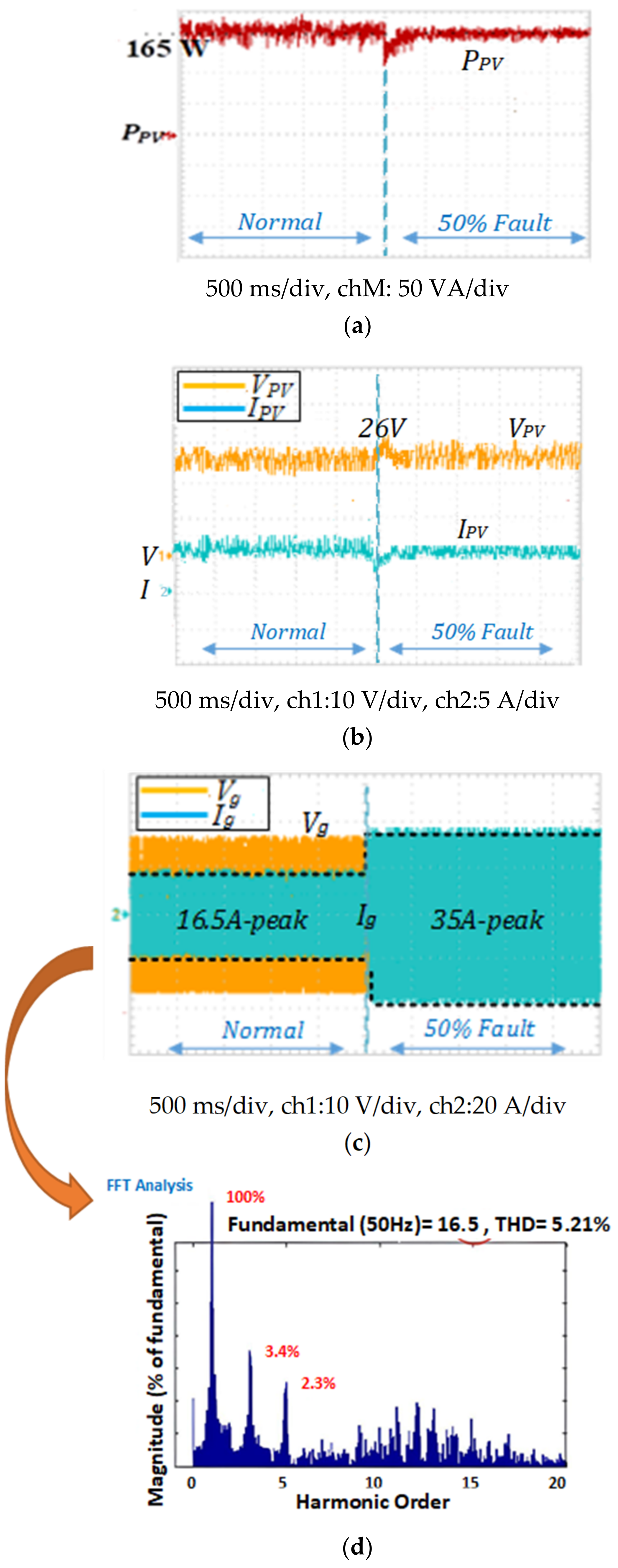
5. Experimental Implementation

An experimental setup is implemented in order to verify the real-time performance of the proposed SCI and its bifunctionality role in limiting grid current increases during grid voltage under-voltages or faults while filtering line current harmonics during normal conditions. Practical validation is applied to a low-power experimental prototype with a schematic diagram and test rig photography shown in Figure 9. The experimental system parameters are listed in Table 4, while the experimental SCI parameters, computed according to the design equations presented in Section 4, are given in Table 5. A detailed comparison between the performance of the conventional output reactor and the proposed SCI during three grid modes—normal mode, 50% fault, and entire short-circuit—is carried out using two main experiments.
In the first experiment, there is a step change from grid normality to 50% grid fault (grid voltage decreases from 1 p.u. to 0.5 p.u.). In this case study, the conventional Lac and the proposed SCI are tested on the experimental rig, and their results are demonstrated in Figure 10 and Figure 11, respectively. On the other hand, the second experiment involves a step change in the grid condition from normality to a total short-circuit (SC) (grid voltage decreases from 1 p.u. to 0 p.u.). Under this severe grid fault condition, only the proposed SCI is retested on the experimental rig, with results shown in Figure 12. This is related to the fact that with the conventional L a s , the grid current will keep increasing under grid short-circuits, as concluded from simulation results, resulting in the inverter breakdown which is not applicable in real life. Hence, in the second experiment, only the proposed SCI is applied to the inverter output to verify its real-time capability of limiting such high current increases during severe grid faults. Both experiments’ results are analyzed, and performance parameters are summarized in Table 6.
For experiment 1 (grid voltage decreases from 1 p.u. to 0.5 p.u.), it is clear that during grid normal conditions ( V g = 1 p.u.), both the conventional L a c and the proposed SCI gave almost similar results and close performance parameters, as shown in the first horizontal segment of Table 6. This involves almost similar characteristics, including (i) tracked PV maximum power of 165 W during test conditions of 800 W/m2 and 25 °C, as shown in Figure 10a and Figure 11a, respectively. (ii) DC-link voltage (i.e., PV voltage) of 26 V, as depicted in Figure 10b and Figure 11b, respectively. (iii) Peaks of grid current reaching 16.5 A and 16.8 A, as shown in Figure 10c and Figure 11c, respectively. Primarily, grid current THD attained by both Lac and SCI is almost 5% (within standards) as depicted in Figure 10d and Figure 11d, respectively, which highlights both devices’ ability to filter grid current harmonics.
However, during the 50% grid fault ( V g = 0.5 p.u.), the performance parameters of both the conventional L a c and the proposed SCI are summarized in the second partition of Table 6. In the case of L a c  = 5 mH, although the PV power and DC-link voltage (i.e., PV voltage) are maintained at 165 W and 26 V, respectively, as concluded from Figure 10a,b, the grid current peak increased to almost 1.75 times its corresponding nominal value, as shown in Figure 10c. In other words, it reached a 35 A peak, which is more than 1.4 times the nominal peak current of 20 A. Hence, it is verified that the conventional Lac is not able to limit grid current increases during grid faults. On the other hand, in the case of the proposed SCI, it succeeded in limiting the increase in grid current where the grid current is maintained at 16.2 A peak (less than the 20 A nominal peak), as evidenced by Figure 11c. Hence, the fault current limiting capability of the proposed SCI is verified, along with its outweighing performance compared to conventional smoothing reactors during grid abnormalities. It is worth noting that to limit the grid current increase during grid faults, the proposed SCI imposes a vast impedance within the circuit, which minimizes average power injection into the grid and eliminates grid current increase. Hence, the PV operating point changes ( P P V = 15 W and V P V = VDC = 30 V) to limit the harvested PV power, as concluded from the PV power and voltage values shown in Figure 11a,b respectively.
For further validation of the proposed SCI capability to limit huge increases in grid current during severe grid faults, experiment 2 is carried out. In this experiment, grid voltage decreases from 1 p.u. to 0 p.u. while applying only the proposed SCI whose results are shown in Figure 12 and whose performance parameters are listed in the third segment of Table 6.
As shown in Figure 12c, the proposed SCI can successfully limit the peak grid current to 25 A, which is still within safe limits (i.e., less than 1.4 of the nominal 20 A grid current peak). Hence, its FCL effectiveness is confirmed even during severe grid conditions. It is worth noting that to limit the grid current increase during grid faults and short circuits, the proposed SCI imposes a vast impedance within the circuit, as previously explained. This minimizes average power injection into the grid to eliminate grid current increases above 1.4 times their nominal value. Hence, the DC-link voltage, i.e., the PV voltage, will experience almost its open-circuit value (32.9 V) as per Figure 12b, and minimal PV power of 5 W will be harvested as per Figure 12a, just adequate for DC-link compensation and average power dissipation in the reactor’s resistance. Yet, the power flow has not ceased, nor has the circuit breaker been tripped. Thus, whenever the fault is cleared, the SCI will return to its normal small impedance, and normal active power harvesting and injection into the grid will take place.
In summary, experimental results verify those attained during simulation work, which validates the bifunctionality and FCL ability of the proposed SCI. Similar to the conventional Lac, the proposed SCI has the filtering and smoothing ability to minimize the grid current harmonics and maintain its THD within standards. However, during grid faults, the proposed SCI has an extra FCL feature, outweighing performance. Unlike the conventional Lac, the proposed SCI can successfully limit increases in grid current during faults, even severe short-circuit ones, thus enhancing system reliability, efficiency, and robustness.

6. Discussion

As demand for electric energy increases, many distributed generation systems are being integrated into the power system. However, the increase in the penetration of variable renewable sources, transmission congestion, increased network complexity, and aging of power grid components all contribute to higher short-circuit levels. This poses additional challenges for preventing interruptions and blackouts, particularly with single-stage grid-tied renewable energy systems. Although single-stage topologies are less complex and more efficient compared to two-stage ones, many challenges are associated with their operation, particularly during grid faults. The unstable inverter operation of the inverter during faults, the dynamics after fault clearance, and the need to withstand high short-circuit currents pose challenges to the topology of the system. It is important to find solutions that address these challenges without adding complexity to the control system [36,37]. Economically, introducing FCLs into the power grid can be a good option to tackle these issues. As can be noted from Table 7, the literature presents numerous types of FCLs that have been utilized in different applications.
FACTs-based topologies are common in high- and medium-voltage transmission and distribution networks to achieve functions of power flow control. However, the costs of their design for fault current limitation as a secondary functionality might make it a non-viable option [23]. Similarly, solid-state FCL topologies are suitable for distribution networks, yet at a lower cost and weight. However, both topologies, being dependent on several semiconductor switches, suffer from switching losses, thermal management problems, high harmonic generation, reliability issues, and high failure rates [33].
Superconducting FCLs are a hotspot in the field of current limiters, experiencing minimal harmonic generation. However, they are limited by refrigeration systems, which in turn increase their size, weight, maintenance requirements, and costs [33].
To balance the limitations and advantages of the previous topologies, a hybrid topology is developed that combines the solid-state and superconducting topologies. However, its initial and operating costs, as well as its harmonic generation, make it still not appealing for single-staged RES, where minimal THD is mandatory to eliminate their direct impact on the MPPT process and the harvested power ripples. Although permanent magnet FCLs have the advantages of low harmonic interference and small size, they are considered a high-cost option [33].
Alternatively, the proposed SCI offers an ideal option for single-stage grid-tied PV systems in terms of cost, size, control complexity, harmonic generation, reliability, and robustness. In addition, it exploits non-linear magnetic properties, enabling it to serve two functions, primarily as a FCL and also as a smoothing inductor. This eliminates the use of dedicated FCL equipment for short-circuit current mitigation. Finally, as a FCL, it automatically reacts to the fault, so a fast response is guaranteed and a delayed operation is avoided. Once the fault is cleared, the high impedance of the proposed device becomes negligible in the power system. The core of the device returns to the saturation region, resulting in a small impedance that is primarily used for grid current filtering purposes.

7. Conclusions

In this paper, a non-superconducting saturated-core inductor (SCI) is proposed to replace the smoothing inductor at the output of the single-stage PV inverter. Instead of relying on an additional device for fault current limitation, the proposed SCI technique serves two functions simultaneously. Its impedance is varied according to utility operation by controlling its core flux by adjusting its input DC saturation current. Normally, it is used as a smoothing filter with minimal impedance for minimizing line current harmonics, while during grid abnormalities, it features high impedance to limit grid fault currents. The proposed topology does not add to the PV inverter control complexity and is quite promising for its relatively low cost and size, as well as its high reliability and harmonic filtering ability when compared to existing FCL topologies. Its design, modeling, and operation are thoroughly explained. The bi-functionality of the proposed SCI technique in single-stage PV grid-tied systems has been verified through simulated system results and experimental testing on a test rig.

Author Contributions

Conceptualization, N.E.Z.; Methodology, R.A.I.; Software, N.E.Z.; Validation, N.E.Z.; Formal analysis, R.A.I.; Writing—original draft, R.A.I.; Writing—review & editing, N.E.Z.; Visualization, R.A.I. All authors have read and agreed to the published version of the manuscript.

Funding

This research received no external funding.

Data Availability Statement

No new data were created or analyzed in this study.

Conflicts of Interest

The authors declare no conflict of interest.

References

  1. Burke, M.J.; Stephens, J.C. Political Power and Renewable Energy Futures: A Critical Review. Energy Res. Soc. Sci. 2018, 35, 78–93. [Google Scholar] [CrossRef]
  2. GSR2022_Full_Report. REN21. 2022. pp. 28–29. Available online: https://www.ren21.net/gsr-2022/ (accessed on 10 April 2023).
  3. Memar, M.-R.; Moazzami, M.; Shahinzadeh, H.; Fadaei, D. Techno-Economic and Environmental Analysis of a Grid-Connected Photovoltaic Energy System. In Proceedings of the 2017 Conference on Electrical Power Distribution Networks Conference (EPDC), Semnan, Iran, 19–20 April 2017; pp. 124–130. [Google Scholar]
  4. Nwaigwe, K.N.; Mutabilwa, P.; Dintwa, E. An Overview of Solar Power (PV Systems) Integration into Electricity Grids. Mater. Sci. Energy Technol. 2019, 2, 629–633. [Google Scholar] [CrossRef]
  5. Landera, Y.G.; Zevallos, O.C.; Neto, R.C.; Castro, J.F.d.C.; Neves, F.A.S. A Review of Grid Connection Requirements for Photovoltaic Power Plants. Energies 2023, 16, 2093. [Google Scholar] [CrossRef]
  6. Bollipo, R.B.; Mikkili, S.; Bonthagorla, P.K. Critical Review on PV MPPT Techniques: Classical, Intelligent and Optimisation. IET Renew. Power Gener. 2020, 14, 1433–1452. [Google Scholar] [CrossRef]
  7. Khan, M.Y.A.; Liu, H.; Yang, Z.; Yuan, X. A Comprehensive Review on Grid Connected Photovoltaic Inverters, Their Modulation Techniques, and Control Strategies. Energies 2020, 13, 4185. [Google Scholar] [CrossRef]
  8. Jagadeesan, G.M.; Pitchaimuthu, R.; Sridharan, M. A Two-Stage Single-Phase Grid-Connected Solar-PV System with Simplified Power Regulation. Chin. J. Electr. Eng. 2022, 8, 81–92. [Google Scholar] [CrossRef]
  9. Ankit; Sahoo, S.K.; Sukchai, S.; Yanine, F.F. Review and Comparative Study of Single-Stage Inverters for a PV System. Renew. Sustain. Energy Rev. 2018, 91, 962–986. [Google Scholar] [CrossRef]
  10. Reddy, K.R.; Reddy, V.N.; Kumar, M.V.; Tummala, S.K. Configurations and Control Strategy of a Single Stage Grid Connected PV System. E3S Web Conf. 2020, 184, 01074. [Google Scholar] [CrossRef]
  11. Hu, H.; Harb, S.; Kutkut, N.; Batarseh, I.; Shen, Z.J. A Review of Power Decoupling Techniques for Microinverters With Three Different Decoupling Capacitor Locations in PV Systems. IEEE Trans. Power Electron. 2013, 28, 2711–2726. [Google Scholar] [CrossRef]
  12. Mastromauro, R.A.; Liserre, M.; Dell’Aquila, A. Control Issues in Single-Stage Photovoltaic Systems: MPPT, Current and Voltage Control. IEEE Trans. Ind. Inf. 2012, 8, 241–254. [Google Scholar] [CrossRef]
  13. Arafa, O.M.; Mansour, A.A.; Sakkoury, K.S.; Atia, Y.A.; Salem, M.M. Realization of Single-Phase Single-Stage Grid-Connected PV System. J. Electr. Syst. Inf. Technol. 2017, 4, 1–9. [Google Scholar] [CrossRef]
  14. Kou, G.; Chen, L.; Vansant, P.; Velez-Cedeno, F.; Liu, Y. Fault Characteristics of Distributed Solar Generation. IEEE Trans. Power Deliv. 2020, 35, 1062–1064. [Google Scholar] [CrossRef]
  15. Buzo, R.F.; Barradas, H.M.; Leão, F.B. Fault Current of PV Inverters Under Grid-Connected Operation: A Review. J. Control. Autom. Electr. Syst. 2021, 32, 1053–1062. [Google Scholar] [CrossRef]
  16. Mirhosseini, M.; Pou, J.; Agelidis, V.G. Single- and Two-Stage Inverter-Based Grid-Connected Photovoltaic Power Plants with Ride-Through Capability Under Grid Faults. IEEE Trans. Sustain. Energy 2015, 6, 1150–1159. [Google Scholar] [CrossRef]
  17. Nasiri, M.; Arzani, A.; McCormack, S.J. A Simple and Effective Grid-Supporting Low Voltage Ride-through Scheme for Single-Stage Photovoltaic Power Plants. Sol. Energy 2022, 232, 248–262. [Google Scholar] [CrossRef]
  18. Barzegar-Bafrooei, M.R.; Foroud, A.A.; Ashkezari, J.D.; Niasati, M. On the Advance of SFCL: A Comprehensive Review. IET Gener. Transm. Distrib. 2019, 13, 3745–3759. [Google Scholar] [CrossRef]
  19. Joshi, J.; Swami, A.K.; Jately, V.; Azzopardi, B. A Comprehensive Review of Control Strategies to Overcome Challenges During LVRT in PV Systems. IEEE Access. 2021, 9, 121804–121834. [Google Scholar] [CrossRef]
  20. Ibrahim, R.A.; Zakzouk, N.E. A PMSG Wind Energy System Featuring Low-Voltage Ride-through via Mode-Shift Control. Appl. Sci. 2022, 12, 964. [Google Scholar] [CrossRef]
  21. Safaei, A.; Zolfaghari, M.; Gilvanejad, M.; Gharehpetian, G.B. A Survey on Fault Current Limiters: Development and Technical Aspects. Int. J. Electr. Power Energy Syst. 2020, 118, 105729. [Google Scholar] [CrossRef]
  22. El-Ela, A.A.A.; El-Sehiemy, R.A.; Shaheen, A.M.; Ellien, A.R. Review on Active Distribution Networks with Fault Current Limiters and Renewable Energy Resources. Energies 2022, 15, 7648. [Google Scholar] [CrossRef]
  23. Gonçalves Sotelo, G.; Santos, G.d.; Sass, F.; França, B.W.; Nogueira Dias, D.H.; Zamboti Fortes, M.; Polasek, A.; de Andrade, R., Jr. A Review of Superconducting Fault Current Limiters Compared with Other Proven Technologies. Superconductivity 2022, 3, 100018. [Google Scholar] [CrossRef]
  24. Shen, B.; Chen, Y.; Li, C.; Wang, S.; Chen, X. Superconducting Fault Current Limiter (SFCL): Experiment and the Simulation from Finite-Element Method (FEM) to Power/Energy System Software. Energy 2021, 234, 121251. [Google Scholar] [CrossRef]
  25. Motamedinejad, M.B.; Radmehr, M.; Radmehr, M.; Firouzi, M. Modified Solid-State Fault Current Limiter Based on AC/DC Reactor. Int. J. Electron. 2022, 109, 1214–1232. [Google Scholar] [CrossRef]
  26. Yuan, J.; Gan, P.; Zhang, Z.; Zhou, H.; Wei, L.; Muramatsu, K. Saturated-Core Fault Current Limiters for AC Power Systems: Towards Reliable, Economical and Better Performance Application. High Volt. 2020, 5, 416–424. [Google Scholar] [CrossRef]
  27. Ninad, N.A.; Lopes, L.A.C. Operation of Single-Phase Grid-Connected Inverters with Large DC Bus Voltage Ripple. In Proceedings of the 2007 IEEE Canada Electrical Power Conference, Montreal, QC, Canada, 25–26 October 2007; pp. 172–176. [Google Scholar]
  28. Araujo, S.V.; Zacharias, P.; Mallwitz, R. Highly Efficient Single-Phase Transformerless Inverters for Grid-Connected Photovoltaic Systems. IEEE Trans. Ind. Electron. 2010, 57, 3118–3128. [Google Scholar] [CrossRef]
  29. Zakzouk, N.E. Mitigation of Oscillating Power Effect on PV Power and Grid Current in Single-Phase Single-Stage PV Grid-Tied Systems. In Proceedings of the 2018 7th International Conference on Renewable Energy Research and Applications (ICRERA), Paris, France, 14–17 October 2018; pp. 437–442. [Google Scholar]
  30. Farhangi, B.; Farhangi, S. Comparison of Z-Source and Boost-Buck Inverter Topologies as a Single Phase Transformer-Less Photovoltaic Grid-Connected Power Conditioner. In Proceedings of the 37th IEEE Power Electronics Specialists Conference, Jeju, Korea, 18–22 June 2006; pp. 1–6. [Google Scholar]
  31. Zakzouk, N.E.; Elsaharty, M.A.; Abdelsalam, A.K.; Helal, A.A.; Williams, B.W. Improved Performance Low-cost Incremental Conductance PV MPPT Technique. IET Renew. Power Gener. 2016, 10, 561–574. [Google Scholar] [CrossRef]
  32. Blaabjerg, F.; Teodorescu, R.; Liserre, M.; Timbus, A.V. Overview of Control and Grid Synchronization for Distributed Power Generation Systems. IEEE Trans. Ind. Electron. 2006, 53, 1398–1409. [Google Scholar] [CrossRef]
  33. Zakzouk, N.E.; Abdelsalam, A.K.; Helal, A.A.; Williams, B.W. PV Single-Phase Grid-Connected Converter: DC-Link Voltage Sensorless Prospective. IEEE J. Emerg. Sel. Top. Power Electron. 2017, 5, 526–546. [Google Scholar] [CrossRef]
  34. Zhang, S.; Chen, D.; Bai, B. Study of a High-Power Medium Frequency Transformer Using Amorphous Magnetic Material. Symmetry 2022, 14, 2129. [Google Scholar] [CrossRef]
  35. Ali, M.A.; Moussa, M.F.; Dessouky, Y.G. Designing a Magnetic Amplifier Used for DC Speed Control. In Proceedings of the 2019 21st International Middle East Power Systems Conference (MEPCON), Cairo, Egypt, 17–19 December 2019. [Google Scholar]
  36. Nasiri, M.; Arzani, A.; Guerrero, J.M. LVRT Operation Enhancement of Single-Stage Photovoltaic Power Plants: An Analytical Approach. IEEE Trans. Smart Grid 2021, 12, 5020–5029. [Google Scholar] [CrossRef]
  37. Moheb, A.M.; El-Hay, E.A.; El-Fergany, A.A. Comprehensive Review on Fault Ride-Through Requirements of Renewable Hybrid Microgrids. Energies 2022, 15, 6785. [Google Scholar] [CrossRef]
  38. Li, H.; Zheng, T.; Huang, S.; Wang, Y. UPFC Fault Ride-through Strategy Based on Virtual Impedance and Current Limiting Reactor. Int. J. Electr. Power Energy Syst. 2021, 125, 106491. [Google Scholar] [CrossRef]
  39. Li, H.; Zheng, T.; Huang, S.; Tang, Z.; Cao, H. A Fault Ride through Strategy of Unified Power Flow Controller and Its Coordination with Protection. Electr. Power Syst. Res. 2020, 184, 106323. [Google Scholar] [CrossRef]
  40. Ghavidel, P.; Farhadi, M.; Dabbaghjamanesh, M.; Jolfaei, A.; Sabahi, M. Fault Current Limiter Dynamic Voltage Restorer (FCL-DVR) With Reduced Number of Components. IEEE J. Emerg. Sel. Top. Ind. Electron. 2021, 2, 526–534. [Google Scholar] [CrossRef]
  41. Mehedi, I.M.; Al Hasan Joy, J.; Islam, M.R.; Hasan, N.; Al-Saggaf, U.M.; Milyani, A.H.; Iskanderani, A.I.; Abusorrah, A.; Rawa, M.; Bassi, H. Reducing Fault Current by Using FACTS Devices to Improve Electrical Power Flow. Math. Probl. Eng. 2021, 2021, 8116816. [Google Scholar] [CrossRef]
  42. Heidary, A.; Radmanesh, H.; Rouzbehi, K.; Pou, J. A DC-Reactor-Based Solid-State Fault Current Limiter for HVdc Applications. IEEE Trans. Power Deliv. 2019, 34, 720–728. [Google Scholar] [CrossRef]
  43. Heidary, A.; Rouzbehi, K.; Mehrizi-Sani, A.; Sood, V.K. A Self-Activated Fault Current Limiter for Distribution Network Protection. IEEE J. Emerg. Sel. Top. Power Electron. 2022, 10, 4626–4633. [Google Scholar] [CrossRef]
  44. Heidary, A.; Popov, M.; Moghim, A.; Niasar, M.G.; Lekić, A. The Principles of Controlled DC Reactor Fault Current Limiter for Battery Energy Storage Protection. IEEE Trans. Ind. Electron. 2023, 1–9. [Google Scholar] [CrossRef]
  45. Kucukaydin, B.; Arikan, O. A Comparative Study on Applicability of Parallel Resonance Type Fault Current Limiters in Power Systems. Teh. Vjesn. 2022, 29, 993–1001. [Google Scholar] [CrossRef]
  46. Shahbabaei Kartijkolaie, H.; Radmehr, M.; Firouzi, M. LVRT Capability Enhancement of DFIG-Based Wind Farms by Using Capacitive DC Reactor-Type Fault Current Limiter. Int. J. Electr. Power Energy Syst. 2018, 102, 287–295. [Google Scholar] [CrossRef]
  47. Jiang, Z.; Wang, Y.; Dai, S.; Ma, T.; Yuan, X.; Liu, M.; Chen, H.; Wang, M.; Peng, C. Application and Design of Resistive SFCL in ±160 KV MMC-HVdc System. IEEE Trans. Appl. Supercond. 2019, 29, 1–5. [Google Scholar] [CrossRef]
  48. Song, M.; Sheng, C.; Ma, T.; Huang, Y.; Yang, C.; Xin, Y.; Jin, H.; Yang, T.; Xiong, J.; Li, C.; et al. Current Limiting Tests of a Prototype 160 KV/1 KA Resistive DC Superconducting Fault Current Limiter. Supercond. Sci. Technol. 2021, 34, 014002. [Google Scholar] [CrossRef]
  49. Ma, T.; Dai, S.; Song, M.; Li, C. Electromagnetic Design of High-Temperature Superconducting DC Bias Winding for Single-Phase 500 KV Saturated Iron-Core Fault Current Limiter. IEEE Trans. Appl. Supercond. 2018, 28, 1–5. [Google Scholar] [CrossRef]
  50. Li, C.; Zhang, P.; Wang, D.; Song, M.; Ma, T.; Ma, P.; Ge, Z. Cooling Unit for the 500 KV Saturated Iron Core Fault Current Limiter. IEEE Trans. Appl. Supercond. 2019, 29, 1–5. [Google Scholar] [CrossRef]
  51. Hasan, J.; Islam, M.R.; Islam, M.R.; Kouzani, A.Z.; Mahmud, M.A.P. A Capacitive Bridge-Type Superconducting Fault Current Limiter to Improve the Transient Performance of DFIG/PV/SG-Based Hybrid Power System. IEEE Trans. Appl. Supercond. 2021, 31, 5603605. [Google Scholar] [CrossRef]
  52. Zheng, F.; Zhang, J.; Lin, J.; Deng, C.; Huang, J. A Novel Flexible Fault Current Limiter for DC Distribution Applications. IEEE Trans. Smart Grid 2022, 13, 1049–1060. [Google Scholar] [CrossRef]
  53. Eladawy, M.; Metwally, I.A. Compact Designs of Permanent-magnet Biased Fault Current Limiters. IET Electr. Power Appl. 2020, 14, 471–479. [Google Scholar] [CrossRef]
  54. Yuan, J.; Zhang, Z.; Zhou, H.; Gan, P.; Chen, H. Optimized Design Method of Permanent Magnets Saturated Core Fault Current Limiters for HVDC Applications. IEEE Trans. Power Deliv. 2021, 36, 721–730. [Google Scholar] [CrossRef]
Figure 1. Schematic diagram of the considered system.
Energies 16 04206 g001
Figure 2. Applied control scheme for the considered system.
Energies 16 04206 g002
Figure 3. Inner grid current control loop of the applied control scheme.
Energies 16 04206 g003
Figure 4. Outer DC-link voltage control loop of the applied control scheme.
Energies 16 04206 g004
Figure 5. SCI schematic diagram.
Energies 16 04206 g005
Figure 6. SCI design flowchart.
Energies 16 04206 g006
Figure 7. Simulation results for normal, 50%, and 100% faults using L a c of 5 mH: (a) P P V ; (b) V P V ; (c) v g vs. i g ; (d) v g vs. i g for the selected time period; (e) grid current THD for the selected time period.
Energies 16 04206 g007aEnergies 16 04206 g007b
Figure 8. Simulation results for normal, 50%, and 100% faults using SCI: (a) P P V ; (b) V P V ; (c) v g vs. i g ; (d) v g vs. i g for the selected time period; (e) grid current THD for the selected time period.
Energies 16 04206 g008aEnergies 16 04206 g008b
Figure 9. Considered system experimental prototype (a) schematic diagram (b) test rig.
Energies 16 04206 g009
Figure 10. Experimental results for grid 50% fault using L a c of 5 mH (a) P P V ; (b) V P V vs. I P V ; (c) v g vs. i g ; (d) grid current THD for the selected time period.
Energies 16 04206 g010
Figure 11. Experimental results for grid 50% fault using the proposed SCI, (a) P P V ;   (b) V P V vs. I P V ; (c) v g vs. i g ; (d) grid current THD for the selected time period.
Energies 16 04206 g011
Figure 12. Experimental results for grid short-circuit using proposed SCI: (a) P P V ; (b) V P V vs. I P V ; (c) v g vs. i g .
Energies 16 04206 g012
Table 1. Considered simulation system parameters.
ParametersRatings
KC200GT
String (15 × 1)
V M P P = 15 × 26.3 = 394.5 V
I M P P = 1 × 7.61 = 7.61 A
MPP = 3000 W at STC
C d c 2200   µ F ,   for   Δ vdc = ± 2.5%
L a c 5 mH, for THDi = 3%
V d c 395 V
f s w i t c h i n g 15 kHz
Table 2. SCI Parameters for the considered simulation system.
ParameterValue
Rated kVA5000 VA
Main Winding Voltage (rms)220 V
Control Winding Voltage (rms)110 V
Main and Control Winding Resistances0.337 Ω
Frequency50 Hz
Equivalent winding resistance0.4 Ω
Table 3. Performance parameters of the simulation system with L a c and the proposed SCI.
L a c Proposed SCI
Normal at STC (0   t     3 )
P P V 3000 W3000 W
V D C 400 V400 V
I g p e a k 19 A19.5 A
THD %2.41%3.55%
50% Fault (3   t     6 )
P P V 3000 W200 W
V D C 400 V480 V
I g p e a k 38 A19 A
Short-circuit Fault ( t 6 )
P P V 80 W95 W
V D C 500 V at t = 7 s and keeps increasing490 V
I g p e a k 230 A at t = 7 s and keeps increasing27 A
Table 4. Experimental system parameters.
ParametersRatings
KC200GT
panel
V M P P = 26.3 V
I M P P = 7.61
MPP = 200 W at STC
C d c 2200   µ F ,   for   Δ v d c = ± ±2.5%
L a c 5 mH, for THDi = 5%
V d c 26 V
f s w i t c h i n g 15 kHz
Table 5. Experimental SCI parameters.
ParameterValue
Rated kVA5 kVA
Primary Voltage (rms)2 × 100 V
Secondary Voltage (rms)4 × 12
Frequency50 Hz
Table 6. Performance parameters of the considered experimental system.
L a c   =   5   mH Proposed SCI
Normal (800 W/m2, 25 °C)
P P V 165 W165 W
V D C 26 V26 V
I g p e a k 16.5 A16.8 A
THD5%5%
50% Fault
P P V 165 W15 W
V D C 26 V30 V
I g p e a k 35 A16.2 A
Short-circuit Fault
P P V --------5 W
V D C --------33 V
I g p e a k --------25 A
Table 7. Comparison between the most recent existing FCLs and the proposed SCI.
FCL TopologyTypeApplicationCostWeightHarmonics
FACTs-based TopologiesUPFC [38,39]
  • Medium and high voltage grids
  • Distribution network
  • Transmission system
HighHighHigh
DVR [40]
STATCOM [41]
Solid-State-based topologiesSwitched Impedance [42,43,44]
  • Distribution network
  • Transmission network
  • Battery energy storage system
  • HVDC Systems
  • Renewable energy systems
LowModerateHigh
Resonance Type [45]
Capacitive Type [46]
Superconducting TopologyResistive [47,48]
  • HVDC Systems
  • Transmission network
HighHighLow
Saturated Core [49,50]
Hybrid TopologiesBridge Type [51,52]
  • DC power system
  • Wind turbines
  • PV systems
ModerateHighModerate
Non-superconductingPermanent Magnet [53,54]
  • HVDC Application
HighLowLow
Proposed Saturated Core Inductor (SCI)FCL and grid current filter in single-stage grid-tied PV systemsLowModerateLow
Disclaimer/Publisher’s Note: The statements, opinions and data contained in all publications are solely those of the individual author(s) and contributor(s) and not of MDPI and/or the editor(s). MDPI and/or the editor(s) disclaim responsibility for any injury to people or property resulting from any ideas, methods, instructions or products referred to in the content.

