1. Introduction
Designing an underground mine and mining areas requires the analyses of numerous parameters. Therefore, it is essential to focus on geology, hydrogeology, tectonics, and geomechanics, as well as technical and economic factors. The latter include a selection of mining methods, types of machinery used, transport systems, ventilation of underground workings, and even the locations of different mine facilities (both underground and on the surface) [
1,
2,
3,
4,
5,
6,
7]. Another significant factor worth considering during the underground mine design and the scheduling of mining operations is the occurrence of natural hazards, such as methane, water, fire, or rock bursts. Each of these hazards and their coincidences can seriously influence the design of mining operations and their schedules [
8,
9,
10,
11,
12,
13,
14,
15].
Longwall mining is one of the most popular underground methods. It is also the dominating mining method in the Polish coal mining industry. In fact, it is the only mining method used in typical mining operations, excluding the exploitation of pillars, the deposit remains, or the occurrence of challenging geological conditions. Thus, Polish law and the literature sources focus primarily on designing longwall exploitation under the conditions of coincidences of different natural hazards [
7,
8,
13,
16,
17,
18,
19,
20].
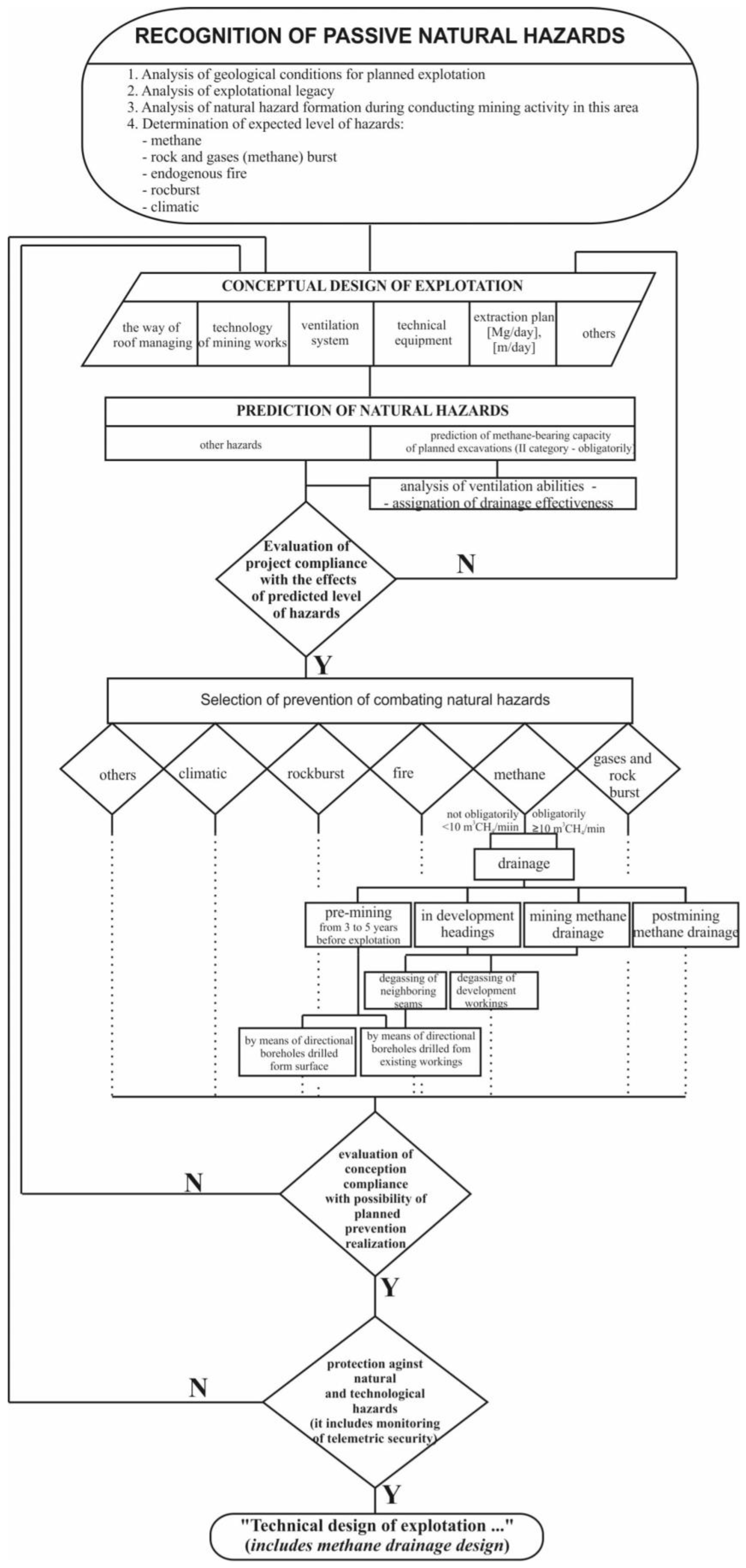
Before designing the exploitation in a new part of the seams, the state of natural hazards should be identified; this is the basis for developing a conceptual design for the exploitation of the deposit. Such a project, in particular if it concerns seams classified as category II of methane hazard [
21], must include, among others, a forecast of the absolute methane-bearing capacity of excavations, which determines the selection of a ventilation system for longwalls and the development of rules and prevention measures for combating the methane hazard. Such an assessment, and the choice of a methane drainage system, can be performed according to the procedure presented in
Figure 1.
As the average exploitation depth in Polish coal mines constantly rises, the significance of the influence of the methane hazard increases along with the rock burst hazard. As a result, numerous methods of assessment of both the absolute methane bearing-capacity of coal seams and the methane emission into the mine workings have been developed for different types of excavations, especially concerning longwalls, where the methane emission into the workings is the greatest. Therefore, a forecast of methane emissions is crucial to ensure proper methods of methane prevention and safe mine operations [
13,
18,
19,
22,
23,
24,
25].
Calculating the methane content of the coal seam is a base for the methane emission forecast. The most popular methane content survey method is presented in the Standard PN-G-44200:2013 [
25]. It is based on the survey of methane emitted from the coal samples collected in gate roads. Samples can be collected by using different methods, such as core drilling conducted during exploratory drilling. The presented approach utilizes an empirical factor obtained during decades of its use in the Polish coal mining industry. The United States Bureau of Mines’ method often verifies the results of the methane content survey, which consists of the constant measurement of methane emission from coal samples collected in the core drilling process [
26,
27,
28,
29].
Interesting studies on determining potential gas hazards have recently been conducted in Ukraine [
30,
31]. The scientists investigated the impact of coal metamorphism on increasing the gas hazard of exploited deposits. In these papers, the authors assessed the effect of changes in the classification indexes that characterize the coal composition in metamorphism processes, making it easier to determine the gas hazards.
The absolute methane-bearing capacity forecasting method, or “dynamic methane emission prognosis method”, developed by GIG Research Institute, is the most commonly used method in the Polish coal mining industry [
22]. This method specifies three different methane emission sources into the mine workings: coal seam exploited, surrounding coal seams and other methane-bearing rock layers, and goafs [
19,
20,
22,
23,
24,
25,
29,
32,
33].
Numerical simulations of methane emission into the mine workings, especially the longwall face, have been gaining popularity in recent years. The GIG Research Institute implemented the finite difference method to verify the dynamic methane emission prognosis method’s results. However, this method requires the development of a detailed deposit model, which can be challenging and can cause inaccuracies, especially in mining areas without previous mining operations. As the method is more expensive and time-consuming, it is not recommended for the general forecast of methane emissions in mining areas [
24,
29,
32,
33,
34].
For new seams, the methane content is determined at various stages of accessing the hard coal deposit. Having assessed it, one can perform a prognosis of absolute methane-bearing capacity in the mine workings. The results of the forecast allow us to start the process of designing coal seam exploitation according to the scheme presented in
Figure 1. First, the ventilation abilities are analyzed and the methane drainage efficiency level is determined. Then, the operation and ventilation system is selected. Then, as additional data are obtained from cutting the coal seam by preparatory works, the methane content is determined at 200 m intervals. On this basis, the final forecast of methane release to the longwall workings is prepared. Based on its results, the appropriate methane drainage system is finally selected and it is determined what other auxiliary ventilation devices will be necessary. It should be borne in mind that, when designing a mining system for newly opened deposits, methane protection systems in the form of telemetric security are also designed each time, following applicable legal standards [
35].
Methane prevention methods that are planned and designed based on the methane emission forecast consist of the proper design of ventilation of the longwall face, calculation of the longwall advance, design of the methane detection system, and design of the drainage system. In addition, as methane is a valuable energy resource, it should be effectively captured and utilized, e.g., for energy production for the own needs of the mine [
36,
37].
The article presents a procedure of methane emission prognosis for mining operations designed in parties A and B of the 404/1 and 403/1 coal seams, considering different longwall advances and daily production as well as further methane utilization.
The purpose of the considerations in the article is to present how to properly design the exploitation in the newly opened deposit of a new mine. The critical issue is assessing the existing natural hazards, particularly methane ones. The procedure of prognosing methane bearing-capacity presented in the article shows how necessary the process of evaluating the state of methane hazard in the planned deposits is. A well-conducted approach for predicting the methane emissions in excavations allows for the proper selection of a ventilation system and, thus, methane drainage and its utilization. The method described in the article can be used in all coal basins when planning new mining. Still, conditions must be met to carefully check the degree of the degassing of the underlying and overlaying seams. In addition, it is essential to know the exploitation history, particularly the magnitude and the changes of the absolute methane emission during the previous exploitation and the time of the goaf’s existence. The factors mentioned above are determined depending on the technical, mining, and geological conditions existing in a given region.
The first part of the article explains the geological and mining conditions of the examined parties of the coal deposit. The second part treats the methane emission prognosis in parties A and B of the 404/1 and 403/1 coal seams. Finally, the third part describes and explains methane capture and its utilization.
2. Geological and Mining Conditions in Parties A and B of 404/1 and 403/1 Coal Seams
2.1. Overview
The mining area is located in the southwestern part of the Silesian Coal Basin, south of the Gorzyce–Bzie–Czechowice tectonic fault and southwest of Jastrzębie–Moszczenica anticline, in the Carpathian Foredeep Basin. The mining area is restricted by:
The Bzie–Czechowice fault zone from the north (with a vertical throw of 800 m),
The B-1 fault from the east (with a throw of about 80–100 m),
A fault from the south and west (throw of about 90 m).
The occurrence of the A and B-1 tectonic faults and the fault zone of the Bzie–Czechowice fault indicate the potential presence of other tectonic faults. Moreover, the rock mass in the vicinity of the tectonic faults, especially in the Bzie–Czechowice fault zone, can have reduced mechanical properties.
According to the mining operations’ schedule of the analyzed mining area, the plan is to conduct the exploitation of coal fields 404/1 and 403/1 below the 1180 m level. Mining operations in the 404/1 coal seam are scheduled between 2022 and 2035 and in the 403/1 seam between 2028 and 2037. Moreover, longwall mining is also planned in B party (B1 and B2) of the 403/2 coal seam between 2029 and 2031.
The basis for the article is the Regulation of the Energy Minister, dated 23 November 2016, regarding specific requirements for the underground mines’ operation. According to Polish law, the 404/1 and 403/1 coal seams are classified into a first-degree water hazard, a fourth methane hazard category, and class B of coal dust explosion hazard both to rock burst, gas, and rock ejection. The rock temperature in the case of both seams is between 45 and 50 °C. The presented mining area is designed for retreat-type longwalls with U-type ventilation.
2.2. 404/1 Coal Seam
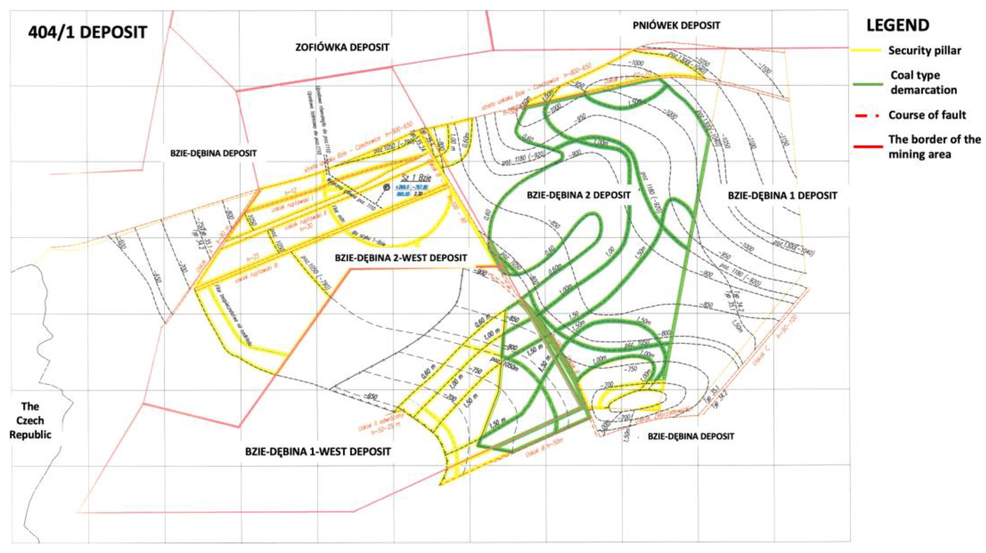
The 404/1 seam of type 35.1 coal is located in parties A and B. Its thickness is between 1.40 and 2.30 m.
Figure 2 presents a map of the 404/1 coal seam. The overlying rocks comprise shale with coal interbeds (0.00–0.80 m), sandstone (up to 2.50 m), and mudstone laminated with sandstone (up to 3.50 m). The deposit floor consists of shale and mudstone with coal interbeds (up to 3.00 m) and concise mudstone (more than 3.00 m deep).
The seam dip angle varies between 2 and 17° and its direction is south and southwest.
Table 1 presents the compressive strength of the coal and the surrounding rocks.
2.3. 403/1 Coal Seam
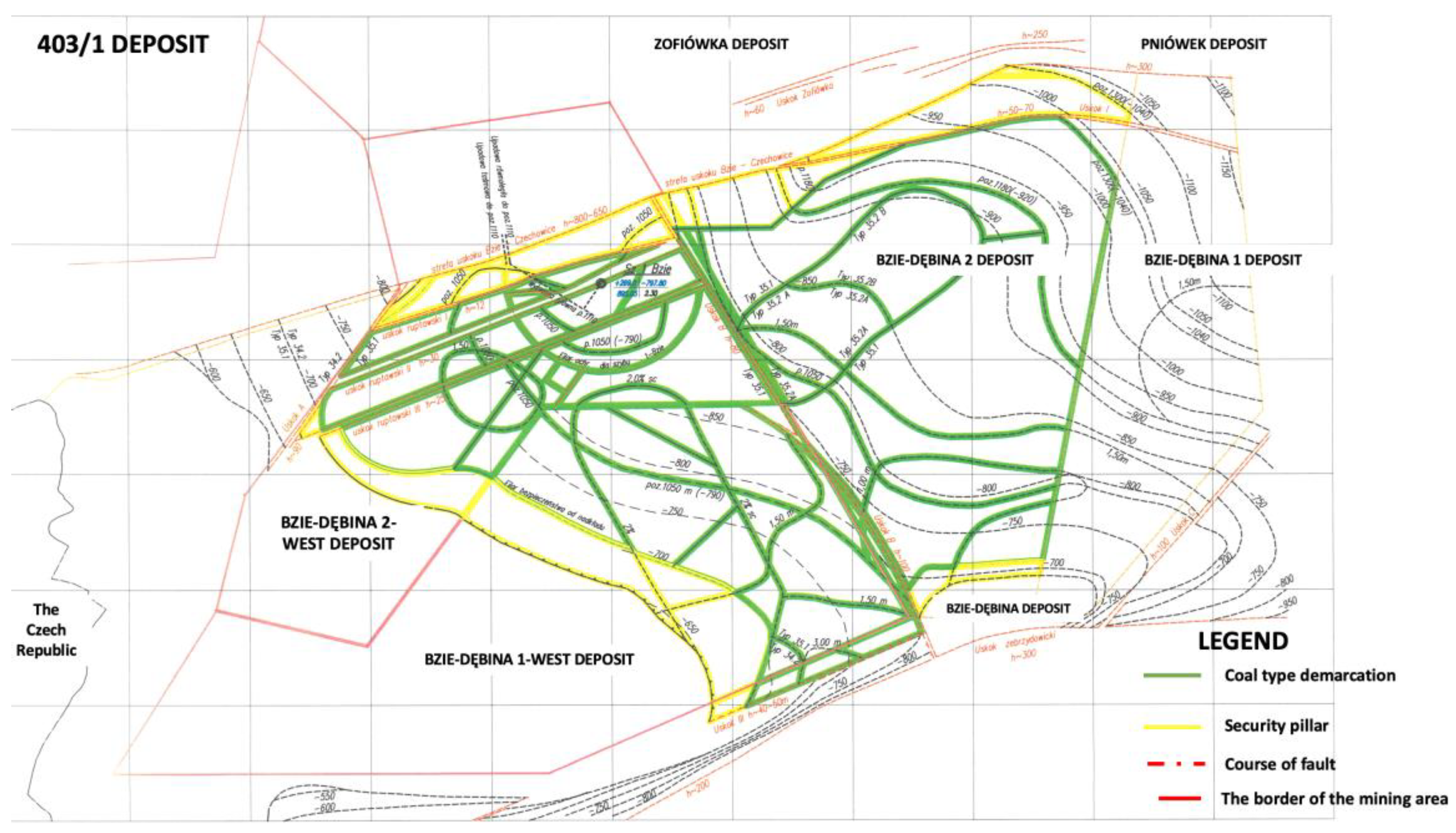
The thickness of the 403/1 coal seam is between 1.14 and 2.40 m.
Figure 3 presents a map of the seam. The deposit is built of 35.1 type coal. The overlying rocks consist of shale, mudstone with shale interbeds, sandstone, and mudstone. The coal seam floor comprises shale with interbeds of sandstone and mudstone.
The seam dip angle varies between 2 and 15° and its direction is south and southwest.
Table 2 presents the compressive strength of the coal and the surrounding rocks.
3. Methane Emission Prognosis
The authors performed a methane hazard analysis between 2022 and 2030 by creating a detailed methane emission forecast based on the coal seams’ methane content, geological profiles, and parameters of the designed longwall panels. The parameters presented above are the main components of the absolute methane emission forecasting method, or the so-called “dynamic methane emission prognosis method”, developed by GIG Research Institute [
22].
The dynamic methane emission prognosis method assumes that the methane content in the coal seams changes linearly with depth. The change quantity depends on the methane content in the surveyed coal seams and the vertical distance between them.
The values of the methane content identified in the mine workings and the boreholes are used in the calculations. Obtaining a methane content gradient is possible by using two or more coal seam methane content values. The methane content in the remaining coal seams is achieved by using this gradient in the further calculations. Additionally, the values of the methane content in the zones under the influence of goaf are adjusted. In such a situation, the methane content in the coal seam is reduced due to degassing caused by mining operations. The methane content values obtained for each coal seam are used as input data to calculate the absolute methane emission. For coal seams in which the methane content is not surveyed in the mine workings or the boreholes, its values are computed using the methane content gradient obtained from the overlying and the underlying seams.
The methane emission prognosis gives an amount of methane emitted to the mine atmosphere from the coal seam in the zone of the influence of mining operations, depending on the longwall advance or its daily production.
Table 3 and
Table 4 present the parameters of the longwall panels designed in the coal seams 404/1 and 403/1. Moreover, besides parties A and B of seams 404/1 and 403/1, there are two longwall panels (B1 and B2) designed in the 403/2 coal seam.
In the adopted procedure, the methane release to the excavation is calculated as the sum of its release from the coal in the mined seam and from the exposed sidewall of the longwall and its release from overlying coal seams, sandstones, exploited coal seams, and underlying rock layers.
In the methane release forecast, it is necessary to determine the desorption zone of the overlying and underlying seams. This is carried out according to the procedure described in Szlazak et al., 2014 and 2021 [
38,
39], knowing the length of the longwall being exploited, the distance from the floor or roof seam to it, and the values of the coefficients for calculating the desorption angles. The value of the latter depends on the angle of inclination of the exploited longwall [
38,
39].
A non-linear function of the longwall advance determines the methane release. When determining the absolute methane-bearing capacity using this method, only variables depending on the longwall progress are considered. In addition to them, other parameters, independent of the progress, should also be taken into account, such as the methane release from the goaf of the longwall and other possible methane inflows into the longwall environment (methane release from old goafs or methane inflow from drilled headings). For this reason, in the presented procedure for determining the absolute methane-bearing capacity, the obtained value of the final emission should be increased by 20%.
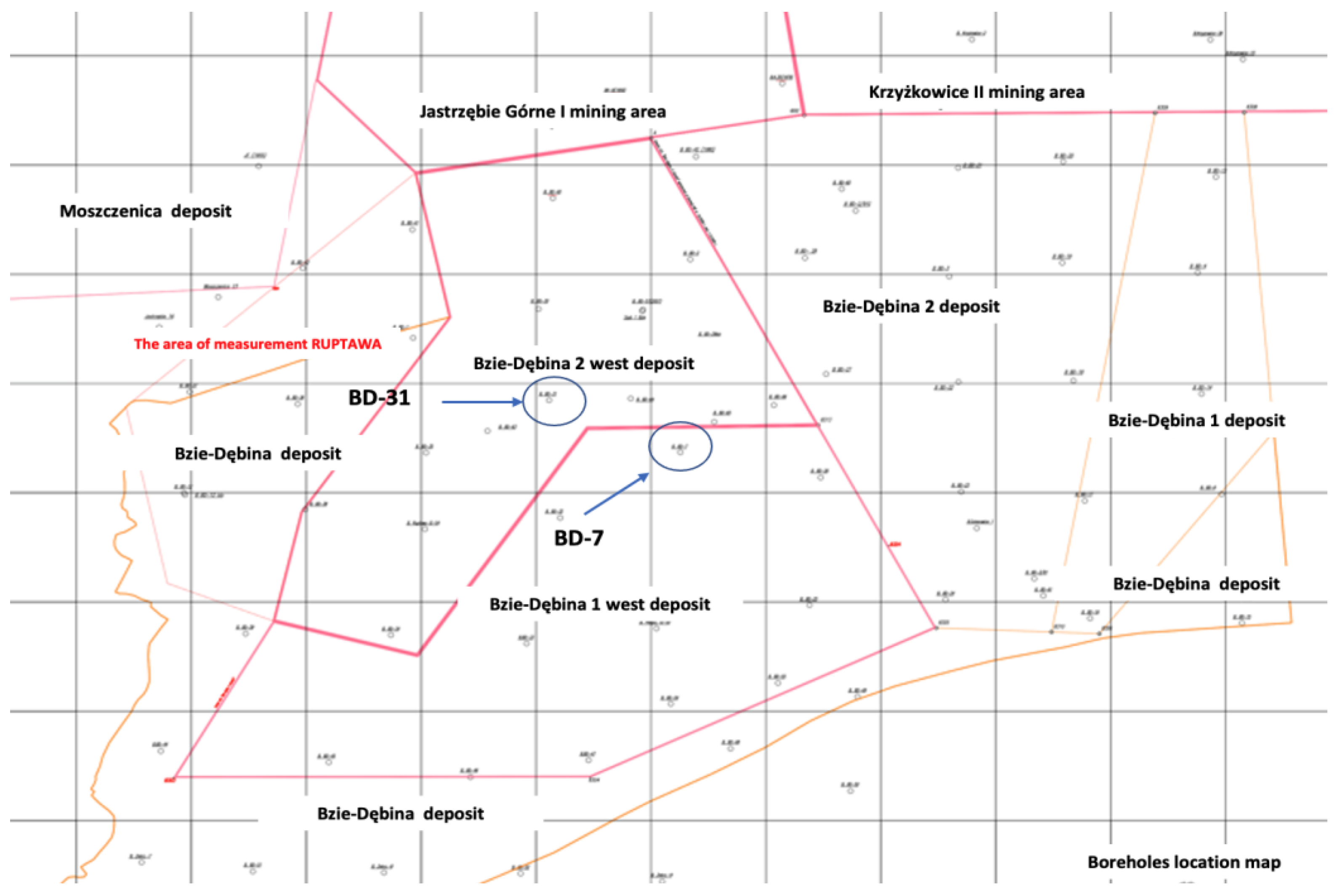
As parties A and B of coal seams 404/1 and 403/1 are poorly surveyed with the mine workings and the boreholes, the methane emission values calculated using the methane content gradient are used in the prognosis.
Table 5 presents values of the methane content of the coal seams considering the geological profile.
Figure 4 shows a map including boreholes BD-31 and BD-7 that are used in the survey and as a base for the methane volume prognosis of party A of both coal seams 404/1 and 403/1.
3.1. Methane Emission Prognosis of Parties A and B of the Coal Seam 404/1
Mining operations have not been carried out in the coal seam 404/1. However, five longwall panels are scheduled to run in party A (A1, A2, A3, A7, and A8). In addition, party B will deliver six extra panels (B1, B2, B3, B6, B7, and B8). The activities mentioned above are planned to be performed between 2022 and 2036.
Table 3 presents the longwall panels’ parameters, while
Figure 5 shows the design of the exploitation of parties A and B of coal seam 404/1.
3.1.1. Party A of the 404/1 Coal Seam
The face length of the designed panels is 200 m each and their height is between 1.6 and 2.1 m. The inclination of the longwall panels is about 10°. Therefore, the degassing range equals 134.23 m for overlying rocks and 50.00 m for underlying rock layers.
The methane content of the 404/1 coal seam used in the calculations is 10.06 m3 CH4/Mgdaf. The schedule of mining operations assumes the exploitation of the A1 panel first and then panels A2, A3, A8, and A7, subsequently.
The longwall panels of party A of the 404/1 coal seam are influenced by the methane emission from the overlying coal seams 403/3, 403/2, 403/1, 402/3, 402/2, 402/1, and 401. An additional influence is visible from seams 363/1, 362/2, and 361/1that are located over 100 m above. Of the overlying rock layers, the 11 m thick layer of fractured sandstone found 7.4 m above and the 1.6 m thick 403/2 coal seam located 28.5 m over the 404/1 coal seam should have the most significant influence on the methane emission. The highest methane emission from the underlying rock layers comes from the 1.2 m thick 404/2 coal seam (13.3 m below the floor of the 404/1 coal seam) and coal seams 404/3 and 404/4 (subsequently 25.7 m and 31.1 below). A sandstone layer with mudstone interbeds located 50 m below the floor of the 404/1 coal seam should not influence the methane emission in the mine workings of the 404/1 coal seam.
Analysis of the influence of the significant methane emission from the different rock layers reveals that the overlying rocks should have the greatest influence on the total methane emission (about 50%), then the 404/1 coal seam (between 32 and 36%), and finally the smallest from the underlying rocks (about 18–19%). The exact values are as follows:
The methane emission from the overlying rocks: between 47.12% in the A2 panel (with advance equal to 1 m/d) and 48.72% in the A3 panel (with advance equal to 7 m/d);
The methane emission from the 404/1 coal seam: between 32.50% in the A1 panel (with advance equal to 7 m/d) and 49.00% in the A3 and A8 panels (with advance equal to 1 m/d);
The methane emission from the underlying rocks: between 17.02% in the A1 panel (with advance equal to m/d) and 19.00% in the A1 and A8 panels (with advance equal to 7 m/d).
Analysis reveals that the maximum total methane emission should occur in the A2 (41.85 m3/min) and the A3 (40.38 m3/min) panels with a daily advance equal to 7 m/d. The total methane emission in the A party of the 404/1 coal seam should not exceed 40 m3/min.
3.1.2. Party B of the Coal Seam 404/1
The face length of the designed panels is 200 m each and their height is between 1.5 and 1.8 m. The inclination of the longwalls is about 10°. Therefore, the degassing range equals 134.23 m for the overlying rocks and 50.00 m for the underlying rock layers. The methane content of the 404/1 coal seam used in the calculations is 10.023 m3 CH4/Mgdaf.
The longwall panels designed in part B of the 404/1 coal seam are influenced by the methane emission from the overlying coal seams 403/2, 403/1, 402/2, 402/1, and 401. An additional influence is visible from seams 363/1, 362/2, 363/3, 362/1, and 361, located over 87 m above. Of the overlying rock layers, the 403/2 and 403/1 coal seams (located 26.4 m and 41.0 m over the 404/1 coal seam, respectively) should have the most significant influence on the methane emission, as well as the 4.3 m thick fine-grained sandstone layer. The biggest methane emission from the underlying rock layers comes from a 1.2 m thick 404/2 coal seam (7.8 m below the floor of the 404/1 coal seam). The underlying sandstone layers should not influence the methane emission in the mine workings of the 404/1 coal seam.
Analysis of the influence of the significant methane emission from the different rock layers reveals that the underlying rocks should have the most critical impact on the total methane emission (about 34–38%), the 404/1 coal seam (between 30 and 33.4%), and the underlying rocks (about 30–33%), accounting for a similar methane emission. The exact values are as follows:
The methane emission from the overlying rocks: between 30.81% in the B3, B6, B7, and B8 panels (with advance equal to 1 m/d) and 33.16% in the B1 panel (with advance equal to 7 m/d);
The methane emission from the 404/1 coal seam: between 30.14% in the B3, B6, B7, and B8 panels (with advance equal to 7 m/d) and 33.37% in the B1 panel (with advance equal to 1 m/d);
The methane emission from the underlying rocks: between 34.42% in the B1 panel (with advance equal to 1 m/d) and 38.18% in the B3, B6, B7, and B8 panels (with advance equal to 7 m/d).
Analysis reveals that the maximum total methane emission should occur in the B1 panel. The total methane emission in the B party of the 404/1 coal seam should not exceed 39 m3/min.
3.2. Methane Emission Prognosis of Parties A and B of the Coal Seam 403/1
Mining operations have not been carried out in the coal seam 403/1. However, three longwall panels will run in party A (A1, A4, and A5) and three in party B (B1, B2, and B3) between 2028 and 2030.
Table 4 presents the longwall panels’ parameters, while
Figure 6 illustrates the design of the exploitation of parties A and B of coal seam 403/1.
3.2.1. Party A of the 403/1 Coal Seam
The face length of the A1 panel is 200 m and its height is 1.6 m, while the face length of the A4 and A5 panels is 230 m, with a height equal to 2.0 m. Therefore, the schedule of mining operations assumes the exploitation of the A1, A2, B1, B2, B3, and B6 in the 404/1 coal seam before the beginning of mining operations in the A1 panel of the 403/1 coal seam.
The inclination of the A1 longwall panel is about 10°. Therefore, the degassing range equals 134.23 m for the overlying rocks and 50.00 m for the underlying rock layers. The methane content of the 403/1 coal seam used in the calculations of the methane emission in the A1 panel is 7.053 m3 CH4/Mgdaf, taking into consideration the degassing caused by the exploitation of the A1 longwall panel in the 404/1 coal seam.
The A1 panel of the 403/1 coal seam is influenced by the methane emission from the overlying coal seams 402/3, 402/2, 402/1, 401, 363/1, 362/2, and 362/1. Additional influence is visible from seams 361 and 360/3, located over 90 m above. Of the overlying rock layers, the 2.1 m thick 402/3 coal seam and the 2.9 m thick 401 coal seam should significantly influence the methane emission. However, due to the degassing caused by the mining operations, coal seam 404/1 should not impact the methane emission in the A1 panel in the 403/1 coal seam. The most significant amount of methane emitted from the underlying rock layers come from the 1.6 m thick 403/2 coal seam (18.8 m below the floor of the 403/1 coal seam), 403/2 and 403/3 coal seams (subsequently 20.0 m and 28.8 below), as well as the 11.7 m thick fine-grained fractured sandstone.
Analysis of the influence of the significant methane emission from the different rock layers reveals that the total methane emission in the A1 longwall panel in the 403/1 coal seam is between 7.61 and 28.09 m3/min. Shares of the methane emission in the A1 panel from the different rock layers are as follows:
The methane emission from the overlying rocks: between 63.01% (with advance equal to 1 m/d) and 64.12% (with advance equal to 7 m/d);
The methane emission from the 403/1 coal seam: between 22.16% (with advance equal 7 m/d) and 23.51% (with advance equal 1 m/d);
The methane emission from the underlying rocks: between 13.48% (with advance equal to 1 m/d) and 13.71% (with advance equal to 7 m/d).
The inclination of the A4 and A5 longwall panels is about 10°. The degassing range is 154.36 m for the overlying rocks and 57.50 m for the underlying rock layers. The methane content of the 403/1 coal seam used in the calculations of the methane emission in the A4 and A5 panels is 8.900 m3 CH4/Mgdaf.
The A4 and A5 panels of the 403/1 coal seam are influenced by the methane emission from the overlying coal seams 402/3, 402/2, 402/1, 401, 363/1, 362/2, and 362/1. Additional influence comes from seams 361 and 360/3, located over 90 m above. Of the overlying rock layers, the 2.1 m thick 402/3 coal seam, the 2.9 m thick 401 coal seam, and the 2.0 m thick 363/1 coal seam should significantly influence the methane emission. As the mining operations in the A4 and A5 longwall panels in the 404/1 coal seam are scheduled after the exploitation of the A4 and A5 longwalls in the 403/1 coal seam, the influence of the methane emission from the 404/1 coal seam should also be taken into consideration. The most considerable methane emission from the underlying rock layers comes from the 1.6 m thick 403/2 coal seam (18.8 m below the floor of the 403/1 coal seam), the 403/2 and 403/3 coal seams (subsequently 20.0 m and 28.8 below), as well as the 11.7 m thick fine-grained fractured sandstone.
Analysis of the influence of the significant methane emission from the different rock layers reveals that the total methane emission in the A4 and A5 longwall panels in the 403/1 coal seam is between 13.53 and 49.67 m3/min, assuming a longwall advance equal to 7 m/d. The designed advance of the longwalls equals 4.4 m/d, so the forecasted methane emission should be about 36.38 m3/min. Shares of the methane emission in the A4 and A5 panels from the different rock layers are as follows:
The methane emission from the overlying rocks: between 55.99% (with advance equal to 1 m/d) and 57.27% (with advance equal to 7 m/d);
The methane emission from the 403/1 coal seam: between 25.85% (with advance equal 7 m/d) and 27.48% (with advance equal 1 m/d);
The methane emission from the underlying rocks: between 16.53% (with advance equal to 1 m/d) and 16.90% (with advance equal to 7 m/d).
3.2.2. Party B of the 403/1 Coal Seam
The face length of the panels of the B party is 200 m each and their height is 1.8, 2.0, and 2.2 m for panels B1, B2, and B3, consecutively. The inclination of the B party longwall panels is about 11°. The degassing range is equal to 134.23 m for the overlying rocks and 50.00 m for the underlying rock layers. The methane content of the 403/1 coal seam used in the calculations of the methane emission in the A1 panel is 7.053 m3 CH4/Mgdaf, taking into consideration the degassing caused by the exploitation of the longwall panels in the underlying 404/1 coal seam.
The panels of party B of the 403/1 coal seam are influenced by the methane emission from the overlying coal seams 402/2, 402/1, 401, 363/1, 362/3, 362/2, and 362/1. Additional influence comes from seams 361, 360/3, 360/1, and 359/3, located over 90 m above. Of the overlying rock layers, the 1.6 m thick 401 coal seam and the 1.0 m thick 402/1 coal seam (located 29.40 m and 22.60 m above the 403/1 coal seam, respectively) should have the most significant influence on the methane emission, as well as the 4.3 m thick layer of fine-grained sandstone. The most significant amount of methane emitted from the underlying rock layers comes from a 1.9 m thick 403/2 coal seam, located 15.1 m below the floor of the 403/1 coal seam. Due to the degassing caused by the mining operations, coal seam 404/1 should not influence the methane emission in the B party of the 403/1 coal seam.
Analysis of the influence of the significant methane emission from the different rock layers reveals that the total methane emission in the B1 party in the 403/1 coal seam is between 6.27 and 28.45 m3/min (for advances equal to 1 m/d and 7 m/d, respectively). The methane emission in the individual longwall panels is 18.29 m3/min for the B2 panel with an advance of 4.4 m/d, 17.26 m3/min for the B3 panel with an advance of 4.5 m/d, and 16.15 m3/min for the B1 panel with an advance 4.5 m/d. Shares of the methane emission in the B party from the different rock layers are as follows:
The methane emission from the overlying rocks: between 54.98% in the B2 panel (with advance equal to 1 m/d) and 57.70% in the B3 panel (with advance equal to 7 m/d);
The methane emission from the 403/1 coal seam: between 28.31% in the B1 panel (with advance equal 7 m/d) and 28.31% in the B1 panel (with advance equal 1 m/d);
The methane emission from the underlying rocks: between 12.57% in the B2 panel (with advance equal to 1 m/d) and 15.02% in the B1 panel (with advance equal to 7 m/d).
3.3. Summary of the Methane Emission Prognosis
Figure 7 presents a relationship between the methane emission and the daily advance for the designed longwalls of parties A and B in the 403/1 and 404/1 coal seams. The smallest value of the methane emission is forecast for the previously degassed B1, B3, B2, and A1 panels in the 403/1 coal seam. For example, with a designed advance is equal to 4.5 m/d, the methane emission is between 15.92 m
3/min in the B1 panel and 20.84 m
3/min in the A1 panel, both in the 403/1 coal seam. In contrast, the most significant values are forecast for the A4 and A5 panels in the 403/1 coal seam, in which this value reaches 36.86 m
3/min with an advance equal 4.5 m/d. The remaining longwall panels are as follows in descending order: A2 (31.08 m
3/min), A3 (30.58 m
3/min), B1 (28.52 m
3/min), A1 (27.72 m
3/min), A8 (26.53 m
3/min), A8 (25.31 m
3/min), B2 (26.06 m
3/min), and B3, B6, B7, and B8 (24.77 m
3/min), all in the 404/1 coal seam with the advance equal 4.5 m/d.
The obtained results of the methane emission in the longwall panels in the 403/1 and 404/1 coal seams indicate that the application of a drainage system is required for all panels, despite the B1 and B2 longwall panels in the 403/2 coal seam.
Forecasting the methane hazard aims to determine the total methane emission of the excavation that is planned for exploitation as precisely as possible. However, it should be emphasized that all forecasts are, of course, a specific approximation of the methane emission, which will be formed only after the beginning of the mining works. The prepared methane emission forecast is based on the results of the methane content measurements in the boreholes, which are subject to error. The uncertainty of determining the methane content using the drill-cutting method is estimated at 16% [
40,
41].
4. Drainage System
4.1. Methane Emission into the Mine Workings between the Years 2022 and 2030
The methane emission forecasts obtained for the individual longwall panels allow for calculating the total methane emission in the analyzed mining area between 2022 and 2030. Besides the methane emission into the longwalls, the forecast values of methane emission into the development workings are taken into consideration.
The total methane emission into the mine workings between 2022 and 2030 is shown in
Figure 8. Moreover, curves presenting the methane emission into the longwalls only (yellow line) and the total methane emission into the longwalls without using a drainage system (blue line) are also shown.
The calculations of the methane emission with the application of a drainage system are conducted, considering two variants of the efficiencies of the drainage, which are 40% (variant I) and 50% (variant II). Analysis of the total methane emission from 2022 to the beginning of 2028 shows even emissions between approximately 30 m3/min and 45 m3/min. A significant increase in methane emission is forecast for half of 2028, when the emission will reach a value between 57.58 m3/min and 100.00 m3/min. A peak of methane emission equal to 134.34 m3/min is predicted for the beginning of 2029. The increase in methane emission will be caused by an intensification of mining operations in the 403/1 coal seam. Between halfway through 2028 and 2030, the predicted values of the methane emission will exceed 100 m3/min. Considering the schedule of mining operations in the fourth decade of the 21st century, the expected values of methane emission will remain at the level of about 100 m3/min.
The methane emission into the mine workings between 2022 and 2030, with a drainage efficiency equal to 40% (variant I), is forecast to be nearly constant at the level not exceeding 40 m3/min (between 2022 and the beginning of 2028), which is strongly associated with the mining operations’ schedule. However, at the beginning of 2029, the methane emission into the mine workings will increase fourfold (93.80 m3/min, orange line), concerning the level from the beginning of 2028 (22.92 m3/min). In variant II, the peak level of methane emission will be about 83.67 m3/min (grey line).
4.2. Utilization of the Captured Methane
According to the prognosis presented in the previous sectors, the methane capture between 2022 and 2028 is forecast to be between 4.82 and 11.70 m3/min, assuming a drainage efficiency at a level of 40%. The methane captured will increase during the second half of 2028, reaching 41.00 m3/min at the beginning of 2029. The methane capture should remain at a level of about 40 m3/min, considering the schedule of mining operations in the years 2030–2040. Consequently, the drainage station should ensure the utilization of 20 m3/min pure methane until 2028. From 2028, its efficiency will increase to about 40 m3/min. Moreover, a 50 percent reserve needs to be taken into calculation. Thus, in the year 2028, a drainage station of the following parameters should be constructed:
The parameters of the station presented above can be ensured with three compressors. Moreover, a reserve compressor should be secured. The regulation range of the compressors’ rotation speed should be between 1000 and 1750 rpm. With the designed methane capture, the required pipeline diameter is 500 mm.
Captured methane has to be utilized. The easiest and most convenient way is to produce chilled water for the mine’s air conditioning system. Another option for methane utilization is its use in gas-powered engines, which have proven to be safe and convenient devices for methane utilization for the production of heat and energy.
4.3. Heat Balance of the Cogeneration System
The methodology for calculating the use of the captured methane is based on the prepared forecast of the cooling capacity demand for the designed excavations to maintain the appropriate temperature following applicable regulations, which for the designed longwalls in the analyzed period is 12 MW. According to the forecast of the amount of captured methane, the concept of its use is presented below.
The basic assumption of the conducted analyses is the utilization of captured methane in a cogeneration system, that is, gas combustion in a gas-powered engine, to produce energy, heat, and chilled water. The calculations assume that by burning in gas engines, a stream of methane captured by methane drainage in the amount of 40 m3/min to 42 m3/min with a concentration of 55%, 24 MW of energy can be obtained. The forecast amount of captured methane allows for the two 4 MW and one 2 MWel engine powering. The heat produced by the cogeneration engines can be used for mine air-conditioning; thus, heat produced by the engines should be used in absorption coolers.
It is assumed that the production of chilled water installation should maximally utilize the heat generated by the engine (low-temperature heat) and exhaust gases (high-temperature heat) in absorption coolers. Moreover, it should also utilize part of the energy in compressor coolers used for chilled water cooling. The advantages cause the maximization of the absorption coolers’ usage caused by its effective utilization of heat generated by the cogeneration system. The task of the absorption coolers is chilling water from 18.5 ± 5 °C to about 6 °C, while the compressor coolers cool the chilled water to the required temperature of 1.5 °C. Calculations show that the chilled water flow through the installation is about 294 m3/h.
The designed parameters of the chilled water and the cooling capacity (equal to 6.0 MWch) require a cooling capacity of the compressors equal to 1.58 MWch. The calculations conducted to balance the cooling capacities are presented in
Table 6.
Figure 9 conceptually shows the use of the methane drainage system, from which (after being burned in the gas engines) we obtain heat from the engine cooling and the exhaust gases. The heat is used in the absorption coolers to obtain chilled water used to cool the air in the mining excavations. The excess methane or unused heat is directed to the mine’s boiler to heat water for the needs of the mine.
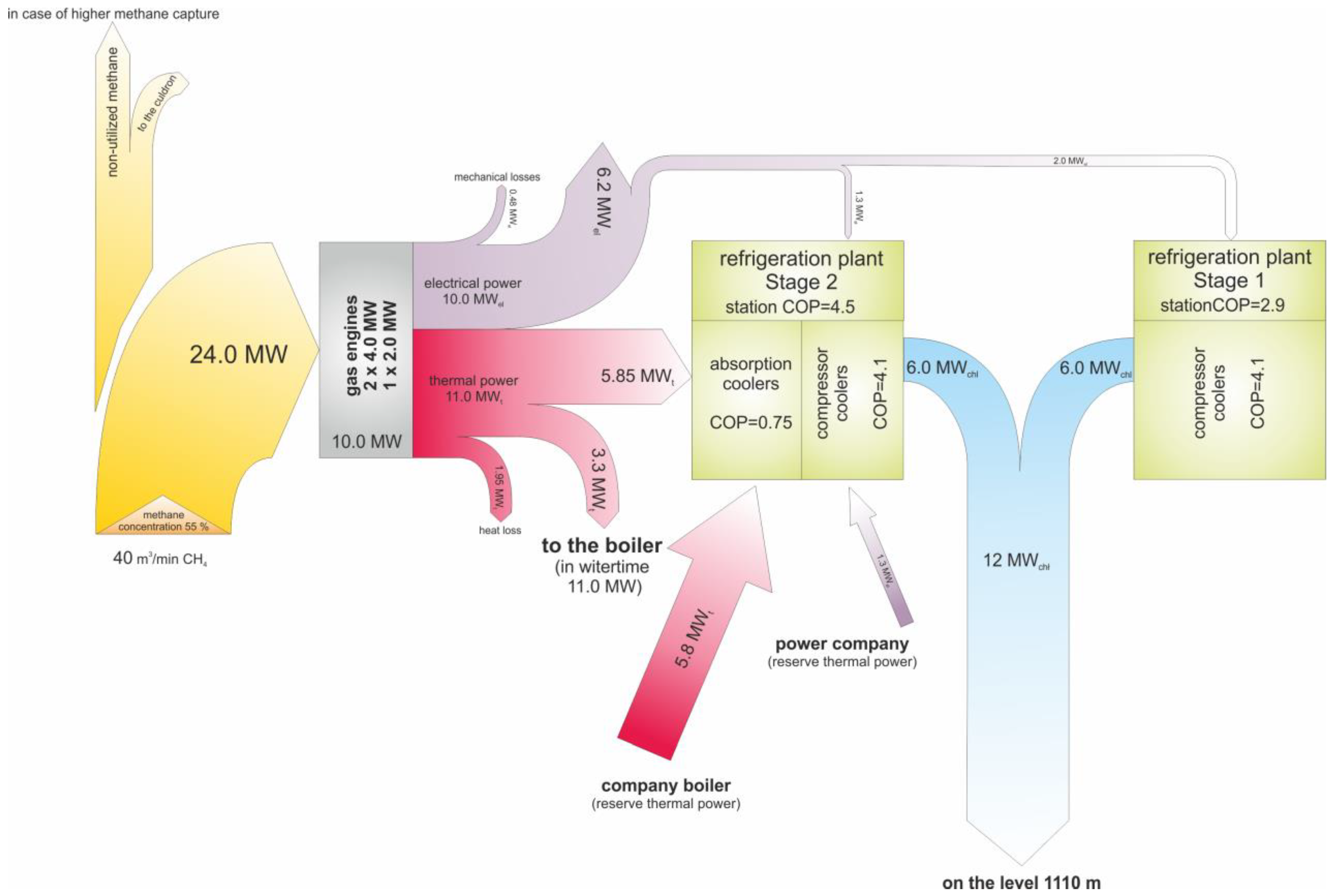
Figure 10, on the other hand, shows in the form of a Sankey diagram the distribution of the amount of energy and heat from the combustion of a stream of 40 to 42 m
3/min of methane from the methane drainage system with a concentration of 55%. A small part of the methane captured by the methane drainage system, which is not used in the gas engines, is directed to the boiler. Most of it, however, is directed to the aforementioned gas engines.
The heat obtained from cooling the gas engines and the combustion is transferred to the boiler room (5 MW) (adsorption) and then the compressor chillers to produce the chilled water. In addition, the heat from the cooling of the engines and the exhaust gases are used in the absorption coolers. By burning a methane stream of 40 m
3/min in the gas engines, 24 MW of energy can be obtained (
Figure 10) and the potential surplus could be used in the heating plant. As a result of the methane combustion, 11 MWt of heat from cooling them is received, which, after deducting 3.3 MWt redirected to the boiler, is transferred to the cooling system (Stage II) in the amount of 5.85 MWt. The electrical power obtained in the engines (10 MWe) is used for the needs of the mine and in the cooling systems (Stage II and Stage I) for cooling the chilled water, which is then transferred further to the areas of mining excavations to cool the air. Losses on the pipelines are the remaining heat in the balance.
In case of the cogeneration system failure, it is necessary to provide heat to the absorption coolers. In the autumn–winter season, when the temperature is too low, absorption coolers are in idle mode and, thus, heat generated by the engines can be used to heat the air in the shaft or the water.
If recipients cannot receive heat generated by the cogeneration system, it should be released into the atmosphere. It can be done by installing a cooling system on top of the cogeneration system.
5. Conclusions
The article presents a procedure of the coal seam exploitation design under the conditions of methane hazard. In such a scenario, it is necessary to prepare a detailed forecast of methane emission in the mine workings, the way of its capturing, and the design of the methane utilization system.
The procedure presented in the article shows how critical the process of evaluating the state of methane hazard in the planned deposits is. A well-conducted approach for predicting methane emissions in excavations allows for the proper selection of a ventilation system and, thus, methane drainage. Furthermore, providing methane capture at an appropriate level of efficiency is extremely important in ensuring the safety of mining crews. Another issue is the management of the captured methane. Designing a system for its utilization allows for its economical use and, at the same time, because it is a greenhouse gas, it reduces its emission into the atmosphere.
Economic issues are aspects that confirm the importance of the conducted research. For example, designing the method of coal seam exploitation in mines is a time-consuming and costly process. Hence, it must be preceded by a reliable and thorough investigation.
The conducted prognosis of methane emission in the analyzed mining area reveals that the most significant amount of methane is to be emitted into the A4 and A5 longwall panels in the 403/1 coal seam. As the designed advance is 4.4 m/d, the methane emission into these longwalls is about 36.38 m3/min. In the case of the second deposit (404/1), the most considerable methane emission is forecast for the A2 (41.85 m3/min) and the B1 longwall panels (25.46 m3/min), both with an advance equal 7 m/d. On the other hand, the lowest value of the methane emission is forecast for the B party of the 403/1 coal seam, i.e., 16.00 and 18.19 m3/min.
It is expected that, from 2022 to 2028, the total methane emission can reach approximately 30 m3/min or even 45 m3/min, with a significant increase from 57.58 m3/min to about 100.00 m3/min predicted for half of 2028. The methane emission values will remain at about 100 m3/min, considering the schedule of mining operations between 2030 and 2040.
Since the analyses showed an increased methane emission, a drainage system will be required in all the designed longwall panels in seams 403/1 and 404/1. Considering the methane emission into the longwalls and the designed U-type ventilation, the calculated drainage effectiveness will be between 38.3 and 40.6%. Higher effectiveness values require the application of a U-type ventilation with drainage, which allows obtaining effectiveness reaching 60.2%, with the methane emission between 20 and 30 m3/min, or even up to 62.6%,with the methane emission between 30 and 40 m3/min. The analysis of the drainage system’s effectiveness shows that between 2022 and 2028, the methane capture will persist between 4.82 and 11.70 m3/min, with drainage effectiveness equal to 40%. A significant increase, up to 41.00 m3/min, is expected in 2029. After that, the methane capture should remain at about 40 m3/min, considering the schedule of mining operations in the years 2030 to 2040.
The captured methane is to be used in the cogeneration system. The heat generated by the gas-powered engines should be used in the absorption coolers, which are used for chilling water for the purposes of the central air-conditioning system of the mine. The energy produced by the cogenerated system is to be used for the own needs of the mine.


