Article

Comparative Analysis of Numerical Methods for Simulating N-Heptane Combustion with Steam Additive

by
Andrey V. Minakov
1,2,*,
Viktor A. Kuznetsov
1,2,*,
Artem A. Dekterev
1,2,
Igor S. Anufriev
1,
Evgeny P. Kopyev
1 and
Sergey V. Alekseenko
1
1
Kutateladze Institute of Thermophysics SB RAS, 630090 Novosibirsk, Russia
2
Department of Thermophysics, Siberian Federal University, 660041 Krasnoyarsk, Russia
*
Authors to whom correspondence should be addressed.
Energies 2023, 16(1), 25; https://doi.org/10.3390/en16010025
Submission received: 23 November 2022 / Revised: 12 December 2022 / Accepted: 18 December 2022 / Published: 20 December 2022
(This article belongs to the Special Issue Heat Transfer Analysis and Modeling in Furnaces and Boilers)

Abstract

:
Currently, thermal power plants operating on hydrocarbon fuels (gas, fuel oil, peat, shale, etc.) are one of the main sources of electricity. An effective and promising method for suppressing harmful emissions (NOx, carbon oxides, soot) from the combustion of fossil fuels is the injection of steam into the combustion chamber. The influence of various mathematical submodels was studied on the accuracy of the numerical simulation of the process of n-heptane combustion in a laboratory burner with steam additive to the reaction zone as a promising chemical engineering method for the disposal of substandard liquid fuels and combustible waste with the production of thermal energy. The problem was solved in a three-dimensional stationary formulation. Systematic verification of these submodels, and a comparison of the results of the calculation with the experimental data obtained were carried out. The comparison with the experimental data was carried out for gas components and temperature distribution at the burner outlet; high agreement of the results was achieved. Optimal submodels of the methodology for calculating the process of fuel combustion in a jet of steam were determined. The best agreement with the experiment data was obtained using the EDC model in combination with a mechanism consisting of 60 components and 305 elementary reactions. More correct simulation results were obtained using the RSM turbulence model and the DO radiation model.

1. Introduction

Combustion is currently used as the main method for the production of energy from fossil fuels. However, during combustion, harmful substances are formed, such as carbon monoxide, nitrogen oxides, soot, unburned hydrocarbons, and others [1,2,3]. These substances are hazardous to human health and the environment. Recently, the issue of reducing toxic emissions from combustion into the atmosphere has become more and more acute. Therefore, the development and research of new ways to reduce harmful emissions are urgent tasks.
There are many approaches to reducing the content of toxic substances in exhaust gases [4,5,6]. One of the widely proven ways to reduce the level of harmful emissions (NOx, CO, etc.) in various applications is the addition of diluents during fuel combustion, in particular steam/water [7,8], as one of the most effective [9]. Thus, a significant reduction in the level of harmful emissions is achieved in [10] when simulating numerically the addition of steam during fuel combustion in an aircraft engine. The combustion of n-dodecane as a model fuel for aviation kerosene with the addition of steam (0–20%) is calculated in [11]. Calculations have shown that an increase in steam supply leads to a decrease in CO and NOx emissions. Along with numerical studies, a number of experimental studies have been carried out to investigate the effect of adding steam/water during fuel combustion, and positive effects have been also noted in these studies. For example, in [12], the effect of adding water/steam (up to 200 wt %) during the combustion of methane and aviation fuel (Jet A) in an aircraft engine turbine model was studied experimentally and numerically. It was shown that if the optimal parameters are observed, a significant reduction in CO and NOx emissions is achieved.
The authors are developing a promising chemical engineering method for burning liquid fuel in a flow of superheated steam, applied to solving the problem of using substandard liquid hydrocarbons with the production of thermal energy [13,14,15]. A large cycle of experimental studies was carried out using laboratory burners [16,17,18]. The influence of burner operation regimes (fuel flow rate, air flow rate, steam flow rate and temperature steam) on thermal characteristics and indicators of harmful emissions of combustion of various types of fuel (diesel, spent engine oil, crude oil, fuel oil, kerosene, and heptane) was studied in [15,18,19,20]. The advantages of using steam to reduce toxic emissions into the atmosphere were shown in [15,16,18]. A reduction of NOx concentration in combustion products up to 70% at high fuel combustion efficiency was achieved in [15,18].
However, experimental studies do not allow comprehensive information about the combustion processes in a steam jet [16] to be obtained. Local limitations in measuring individual parameters, especially in the combustion chamber [18], hamper the detailed description of the process kinetics necessary to control the regimes of fuel combustion when creating new burners. To study the processes inside the combustion chambers, as it is known, mathematical modeling was used. However, numerical simulation of the processes of diesel (or fuel oil, kerosene, and heptane) combustion in a steam jet is a rather complex computational problem that requires separate studies in relation to a specific practical application. To describe the processes of liquid hydrocarbon combustion in a steam jet, there are no universal ready-made solutions for choosing mathematical models and simulation methods. The problem consists of many subprocesses (turbulent flow, spray, fuel evaporation and combustion, mixing of a multicomponent medium, heat transfer, etc.), which complicate the choice of a complex model considerably. In turn, the numerical model will consist of submodels of these subprocesses, which are based on different methods and approaches, taking into account various nuances and assumptions. There are both simple and complex accurate submodels (with the fewest assumptions), which are more costly and require more computational resources. As a result, there is a choice between different approaches in submodels for the description of physical and chemical processes, which allow the parameters with the required accuracy to be determined using acceptable computing resources.
The quality of numerical description of flames depends essentially on the turbulence modeling technique. It is often sufficient to use RANS models to describe turbulence in fuel combustion problems [21,22], but if the flow structure is complex or unstable, it becomes necessary to use the URANS and LES methods [23,24].
The correct choice of the gas combustion model is also important. Three approaches to modeling homogeneous combustion are considered: eddy dissipation concept (EDC), flamelet models, and PDF models [25,26,27,28,29,30,31,32,33,34]. The PDF combustion models most comprehensively describe the chemical reaction at a finite rate in turbulent flames, and allow the use of reaction mechanisms with an arbitrary number of reactions. The concentration of components and temperature in a turbulent flow are treated as random variables using a probability density function (PDF). The solution of transport equations is based on the Monte Carlo method [25,26,27,35]. This approach appears to be a promising tool for combustion simulation, as it allows for the elimination of the closure problems. The main advantage of this method is that it allows the strong nonlinear character of the source terms (due to the chemical reaction) to be properly taken into account. However, this method requires an extremely large amount of computing resources.
The eddy dissipation concept assumes that part of the liquid is completely mixed in part of the volume, in the so-called “fine structures”, where the chemical reaction takes place. The rate and scale of mixing are determined through the local characteristics of the turbulent flow. The relationship between the equations of gas dynamics and chemistry is simplified. Conservation equations for individual components are used, for which the corresponding source terms are calculated on the basis of chemical reaction, using detailed kinetics.
One of the ways that turbulent flow and detailed reaction kinetics at an acceptable computational cost can be combined is the use of the flamelet model [36]. It assumes that a turbulent diffusion flame consists of a large number of single laminar diffusion flames, the so-called flamelets, at the appropriate microscales. The efficiency of calculation is achieved by splitting the tasks of calculating the chemistry and the flow. The method is suitable for solving moderate non-equilibrium phenomena. The advantage of this approach is that it allows the use of kinetic reaction mechanisms with a very large number of reactions. In this case, the calculation time does not increase as significantly as, for example, in the EDC method.
It is well-known that the composition of fuel oil, kerosene, and diesel is very uncertain. The percentage of paraffinic, naphthenic and aromatic hydrocarbons may vary. This creates difficulties in the CFD modeling of combustion processes. The works [37,38,39,40,41] present some options for modeling the combustion of diesel fuel. An analysis of the composition of commercial diesel fuel shows that the mass fraction of carbon is approximately 86% [18]. Thus, n-heptane can be chosen as an approximation, in which the proportion of carbon is 84%.
In the recent work of the authors [42], the combustion of n-heptane in a steam jet was first studied numerically in a laboratory evaporative burner. The proposed mathematical model was tested and the calculation results showed good agreement with the experiment [42,43,44]. An investigation of the effect of forced air and steam supply on combustion characteristics was performed [42]. A radical difference between the effect of steam and air supply on the reduction of nitrogen oxide and soot emissions from the burner was shown [42]. The operating conditions of the burners in a wide range of consumption characteristics of the supplied fuel and steam were studied. It has been established that with an increase in the steam quantity, underburning, the amount of NOx produced, as well as soot, were significantly reduced: the underburning of hydrocarbons was reduced by more than two times, the concentration of NOx was reduced by more than 100 times, and the concentration of soot was reduced by more than 10,000 times.
The analysis of ranking the volume-averaged values of the kinetic rate of the reactions occurring showed that the addition of steam significantly changes the intensity of some reactions [42]. For example, the rates of decomposition reactions of high-molecular hydrocarbons NC7H16 + H = C7H15-2 + H2 and C7H15-2 = C2H5 + C2H4 + C3H6 slow down twice, and the reactions, containing the OH– radical, accelerate significantly (H2 + OH = H2O + H reaction accelerates by 17% and takes third place in the chain of dominant reactions). Thus, an increase in steam concentration affects a complex chemical chain of reactions, and as a result, the dynamics of the formation of substances, including NOx and soot, changes.
In [45], this mathematical model was used to study the combustion of diesel fuel dispersed by a jet of superheated steam in the duct of a vortex burner. For this object, the chosen model also showed good agreement between the experimental data and the calculations. For a vortex burner, the effect of steam and fuel flow rate on the flow structure and physical and chemical processes in the burner and at the nozzle outlet was studied. The flow structure inside the burner and its complex swirling character were shown for the first time.
The primary numerical studies showed [42,45] that in solving such problems, it is important to choose mathematical submodels in order to describe the processes most reliably. Therefore, the problem of further developing mathematical models of the studied process of liquid fuel combustion with steam injection is topical. This study is a continuation of the numerical studies of the authors [42,45]. Unlike previous studies, which were focused on the features of the physicochemical processes occurring in the burners under consideration, this study examines the influence of various numerical methods on the accuracy of the simulation of the combustion processes.
The disadvantage of most of the studies listed in the review is that, as a rule, they do not pay due attention to the issues of substantiating the choice of appropriate submodels and numerical algorithms for describing combustion processes. These studies are mainly devoted to examining the physical mechanisms of the influence of various regime parameters on the combustion characteristics. Moreover, in such studies, as a rule, a standard set of submodels is used and the issue of testing them is not given enough attention. At the same time, the choice of reliable models of such a complex phenomenon is very important, since there are many turbulence models, dozens of chemical kinetic mechanisms, and several models of gas-phase reaction and radiative heat transfer. The results of choosing one model are related to the choice of other models. Therefore, a researcher who is engaged in combustion modeling faces a difficult choice: which combination of models to choose.
The aim of this study is a comparative analysis of numerical methods for modeling the combustion of n-heptane in a steam jet in an evaporative atmospheric burner. The novelty of the study is that the influence of turbulence models, radiative heat transfer models, combustion models, and kinetic mechanisms on the reliability of modeling the combustion of liquid hydrocarbon fuel in a superheated steam jet has been studied numerically for the first time. The results of our study may be helpful to other researchers to make a more informed and justified choice of models.

2. Problem Statement and Research Methods

A burner (Figure 1) was chosen to verify the numerical technique for modeling heptane combustion processes with the addition of steam. The presence of a detailed experiment for a given object allows a comparative analysis of the influence of submodels on the calculation results. The burner has proven itself as a test object when combusting diesel [17], waste oil [44], and heptane [42]. Burner overall dimensions are as follows: height of 180 mm, combustion chamber diameter of 130 mm, combustion chamber diameter of 50 mm, and outlet diameter of 30 mm. Figure 2 shows a detailed diagram of the operation of the burner. A more detailed description of the burner device is shown in [17,43,44].
The gas compositions were measured by gas analyzers Test-1 (Russia) and Testo 350 (Germany). Test-1: to measure O2, an electrochemical sensor (absolute error of 0.2 vol.%) was installed. To measure H2, there was a polarographic sensor (relative error of 5%). CO, CO2 and CnHm were measured separately using an optic sensor with an absolute error of 0.2 vol.%, when measuring up to 5 vol.% (for CO2 this value was 7 vol.%); above this value the main error of the sensor was relative deviation within 5%. Testo 350: NOx (0–300 ppm). The content of nitrogen oxide was recorded by the sensor as the sum of NO and NO2 concentrations. For each of these components, an electrochemical sensor was installed in the gas analyzer. For NO, an absolute error of this device was 2 ppm for measurements of up to 40 ppm and higher with a relative error of 5%; an absolute error for NO2 was 5 ppm when measuring up to 100 ppm and higher with a relative error of 5 %. Gas was taken by a cooled probe (inner channel diameter of 2 mm). Gas sampling was carried out on the burner axis along the entire flame. The sampling time at a point was 90 s and the frequency was 1 Hz. The average temperature in the flame was measured using a Pt-Rh/Pt-Rh thermocouple (relative instrument error of 0.5%), at the same points where the gas was sampled.
N-heptane (formula C7H16) was used as a fuel in this study (Table 1). The regime with fuel flow rate of 0.8 kg/h, superheated steam flow rate of 1.0 kg/h and steam temperature of 260 °C was chosen for the investigation. The selected mode corresponds to the optimal environmental performance and thermal characteristics [17,42]. The selected regime ensures low characteristics NOx = 28 ppm and CO = 15 ppm at a high level of efficiency regarding fuel combustion.
Figure 3 shows the calculated geometry of the object under study. The area into which the flame propagates is made in the form of a cylinder with a radius of 250 mm and a height of 600 mm (Figure 3a). The dimensions were chosen in such a way as to exclude the influence of side and outlet boundaries on the flow. However, since the geometry is axisymmetric up to air inlets, a 30° sector containing 1/12 of the geometry with one hole was taken to reduce the calculation time. The methodical calculations showed that the choice of geometry in the form of a sector was justified. There were no differences from the results of the full three-dimensional formulation. Therefore, for further calculations, the calculation geometry in the form of a three-dimensional sector was chosen (see Figure 3b).
The setting of the boundary conditions is shown in Figure 3b. Periodicity conditions were set on the side faces of the sector. At the fuel and steam inlets, the conditions of a fixed mass flow rate were set with the values corresponding to the experiment. At the outlet of their computational domain and at the air aspiration holes, the conditions of a fixed pressure equal to zero were set.
The influence of the computational mesh detailing the accuracy of the combustion process modeling was studied. For the basic version of the model, three calculations with different grid sizes (0.88, 2.16, and 5.40 million cells) were performed. An analysis showed that the simulation results on the average and most detailed meshes were practically the same. Since the RANS approach was used in this paper to model turbulence, this behavior of the solution depending on the grid is quite typical. However, as can be seen in Figure 4, mesh with 0.88 million cells is not enough to describe the flow and combustion process. Therefore, the 2.16 million cell mesh was chosen for further modeling.
The numerical method for describing the combustion process of diesel fuel in a jet of superheated steam is based on the following concepts. A model of a nonisothermal compressible multicomponent gas based on the solution of the equations of conservation of momentum, mass, energy, equations of radiant heat transfer, component transfer, and description of turbulent characteristics was chosen. Research was carried out using Ansys Fluent.
The fundamental issue influencing the flow structure when describing the flames is the choice of the turbulence modeling technique. In this study, to model turbulence, the most popular RANS turbulence models were considered: k-ε [46], k-ω SST [47,48], and RSM LRR (Launder-Reece and Rodi) [49,50]. These models were tested.
In addition to the calculation of turbulent characteristics, the model of interaction of turbulence and reaction chemistry can significantly affect the reliability of flame simulation. To simulate turbulent combustion in the gas phase, four main approaches widely used in practice were considered: the EBU eddy break-up model [51], the hybrid model (finite-rate/eddy-dissipation) [52], the EDC model [53], and the flamelet-PDF model [36]. The first two approaches of the gas phase combustion are quite simplistic and are usually not applied to model a combustion with a large number of reactions. The EDC model can be used with detailed reaction mechanisms, but it should be borne in mind that this model is more expensive in terms of computing resources. The FGM model is computationally more economic because it does not require the solution to a separate transport equation for each component of the mixture.
To solve the equation of thermal radiation transfer, the methods of discrete ordinates [54] and P1 [55,56] were considered. Gas absorption coefficients were calculated using the gray gas sum model.
In this paper, the combustion of n-heptane is considered. One of the frequently used approximations is the use of n-heptane (formula C7H16) as a model analogue of diesel fuel for CFD simulation. The number of chemical reactions that are used in describing oxidation of liquid hydrocarbon fuel in a jet of superheated steam, first of all, affects the accuracy of describing the combustion parameters in the burner, and secondly, the duration of calculation. To simulate the chemical kinetics of n-heptane combustion, four known mechanisms were used: a global mechanism of one reaction (Table 2) (Ansys Fluent), a mechanism consisting of 42 reactions (Ansys Fluent), a mechanism consisting of 35 components and 60 elementary reactions [57], and a mechanism consisting of 65 components and 305 elementary reactions [58].
Soot formation was taken into account using the Moss—Brooks model [59,60]. In the present paper, the description of forming thermal NOx is determined by a set of temperature-dependent chemical reactions (the Zeldovich mechanism) [61,62]. The temperature in the combustion chamber under study exceeds 1400 °C, so the contribution of fast NOx was also taken into account. There is no nitrogen in the fuel under study; therefore, the fuel mechanism for the formation of nitrogen oxides was not taken into account.
The problem was solved in a stationary formulation. The wall function method was used to simulate the boundary conditions on the walls. Solid wall conditions were set on the burner surfaces. The conservation equations for the gas phase were written as a generalized conservation law in the control volume. For the volume, a finite-difference analogue of the equation was written. To calculate the diffusion fluxes on the faces of control volume, a central-difference scheme of the second order of accuracy was used. When approximating the convective terms, a scheme of the second order of accuracy opposite to the flow was used. The SIMPLE-C procedure was used to relate the velocity and pressure fields.

3. Results

A variant numerical study of n-heptane combustion with a steam additive in an atmospheric evaporative burner was carried out. Distributions of the main aerodynamic, thermal and environmental characteristics in the combustion chamber and in the external flame were obtained. The influence of turbulence models, combustion models, and mechanisms of chemical kinetics on the reliability of numerical calculations was studied.

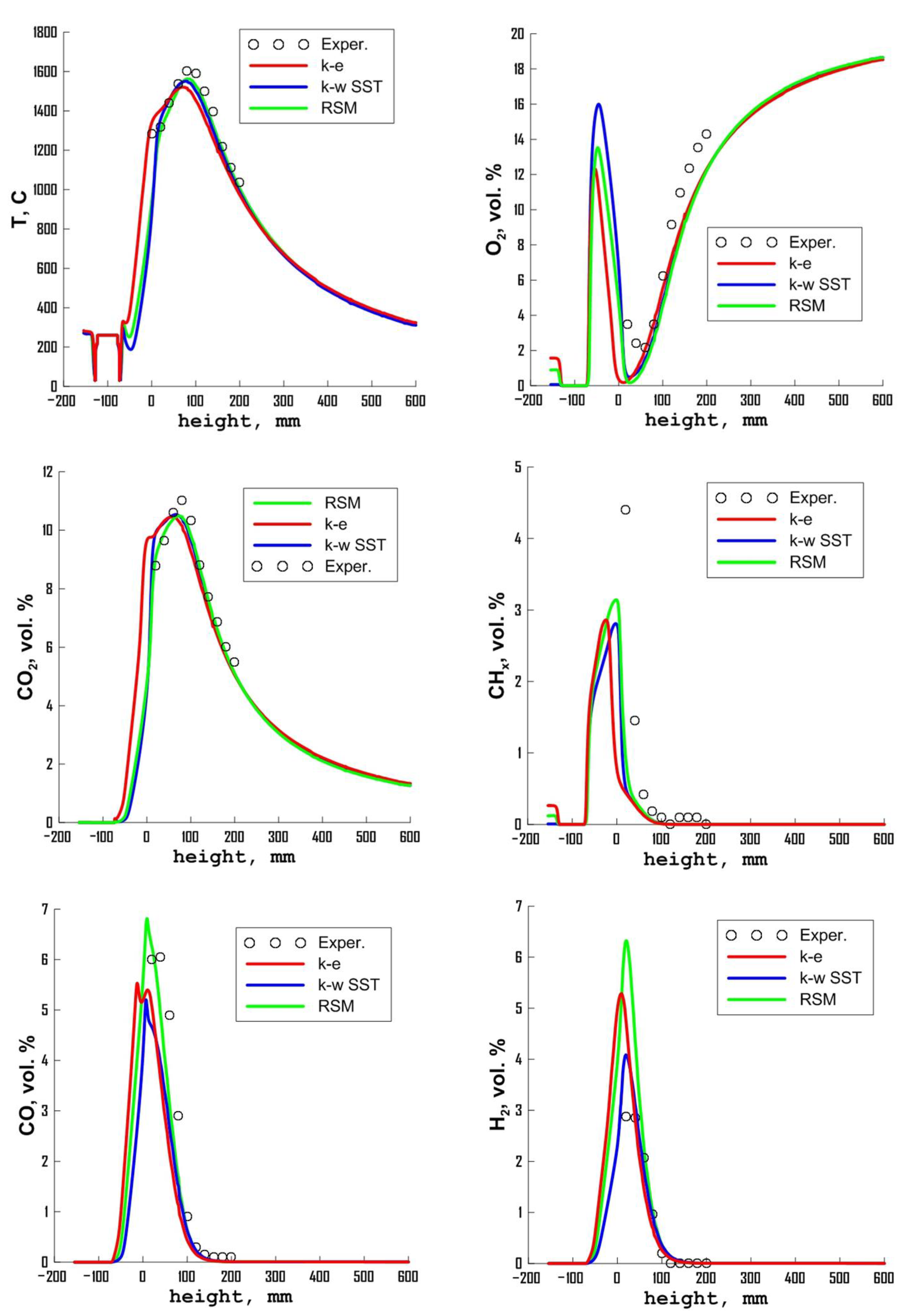
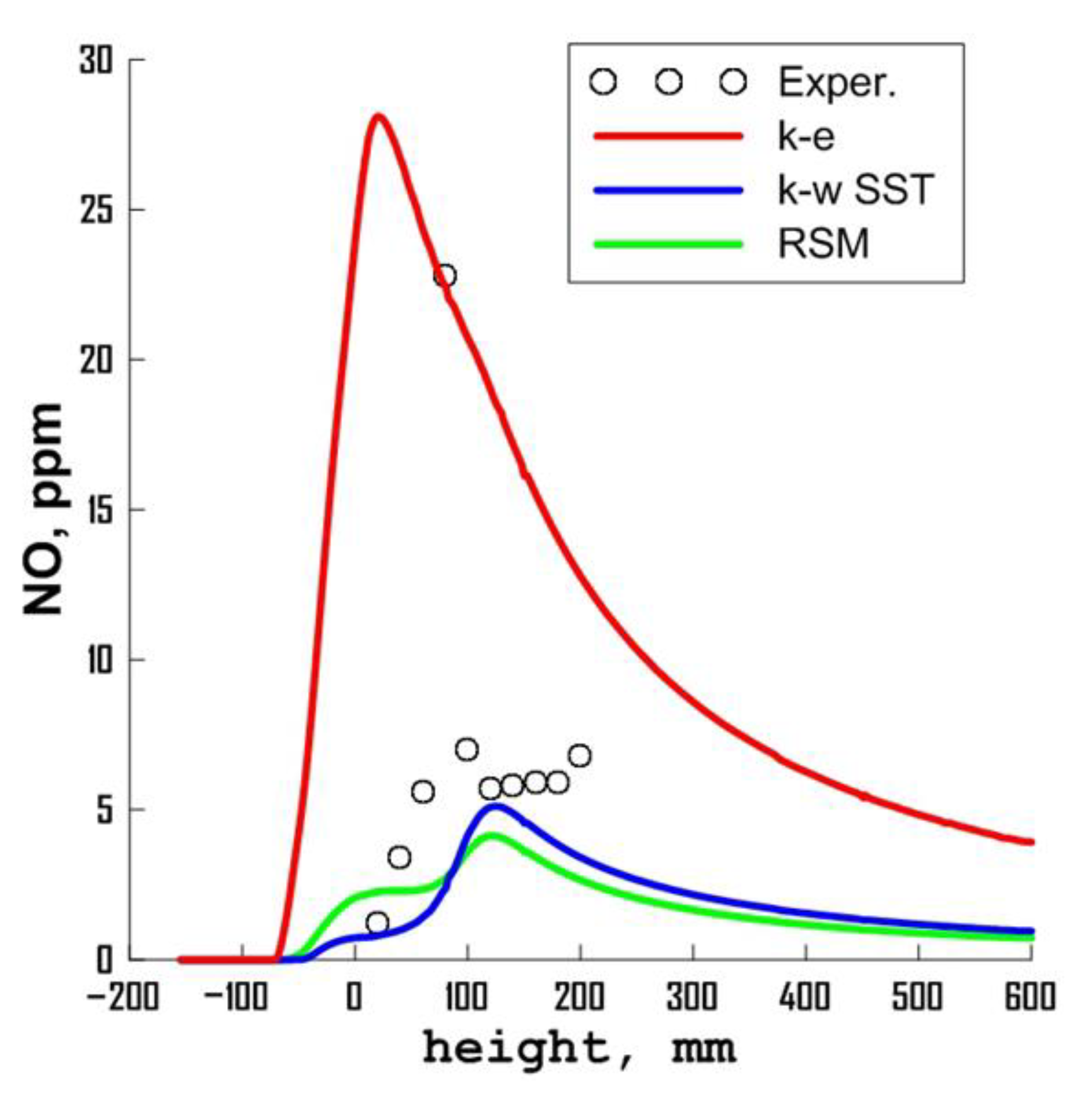
3.1. Influence of Turbulence Models

The influence of turbulence models is studied in detail. The most popular RANS turbulence models were considered: k-ε, k-ω SST, and RSM. The results of the calculation are shown in Figure 5, Figure 6, Figure 7, Figure 8, Figure 9 and Figure 10.
The flow pattern in Figure 5, calculated using various turbulence models, demonstrates a rather complex nature of the flow. A high-speed jet of steam directed upwards ejects gases in the direction of the torch. In some zones, several recirculation zones are formed. The swirling flow at the exit of the nozzle promotes the mixing of fuel, oxidizer and hot flue gases, thereby contributing to stable ignition.
An analysis of simulation results showed that the choice of the turbulence model had an impact on the description of the flow structure inside the burner (see Figure 5). The greatest differences in the vortex structure of the flow are observed at the bottom of the burner. The most significant difference can be seen when calculating with using the k-ε model. This model is characterized by the absence of an annular vortex in the mixing channel. Nevertheless, such a change in the flow structure has a rather weak effect on the distribution of temperature (Figure 6) and the main gas components (Figure 7, Figure 8 and Figure 9). According to the temperature distribution along the burner axis, all models considered gave similar results (Figure 10). The strongest difference in local characteristics calculated using various turbulence models is observed in concentrations of nitrogen oxides shown in Figure 9. When describing the processes of the formation of nitrogen oxides, temperature fluctuations and turbulent characteristics were taken into account. Overestimation of turbulent and temperature fluctuations, given by the k-ε model, leads to significant overestimation of nitrogen oxides. One experimental point falls outside of the main level of nitrogen oxides on the plume axis.
The results of quantitative comparison of calculations with the experiment are shown in Figure 10. The graphs show the distribution of temperature and main gas components along the burner axis. Experimental data are presented starting from the nozzle outlet. A comparative analysis shows that, with the exception of nitrogen oxides, all models considered give fairly close results. In general, the data obtained using the RSM turbulence model are closer to the experiment. Therefore, the use of a more advanced RSM model in this case is more preferable than the linear eddy viscosity models. However, from a practical point of view, in terms of computational costs, the use of the k-ω SST model is optimal.

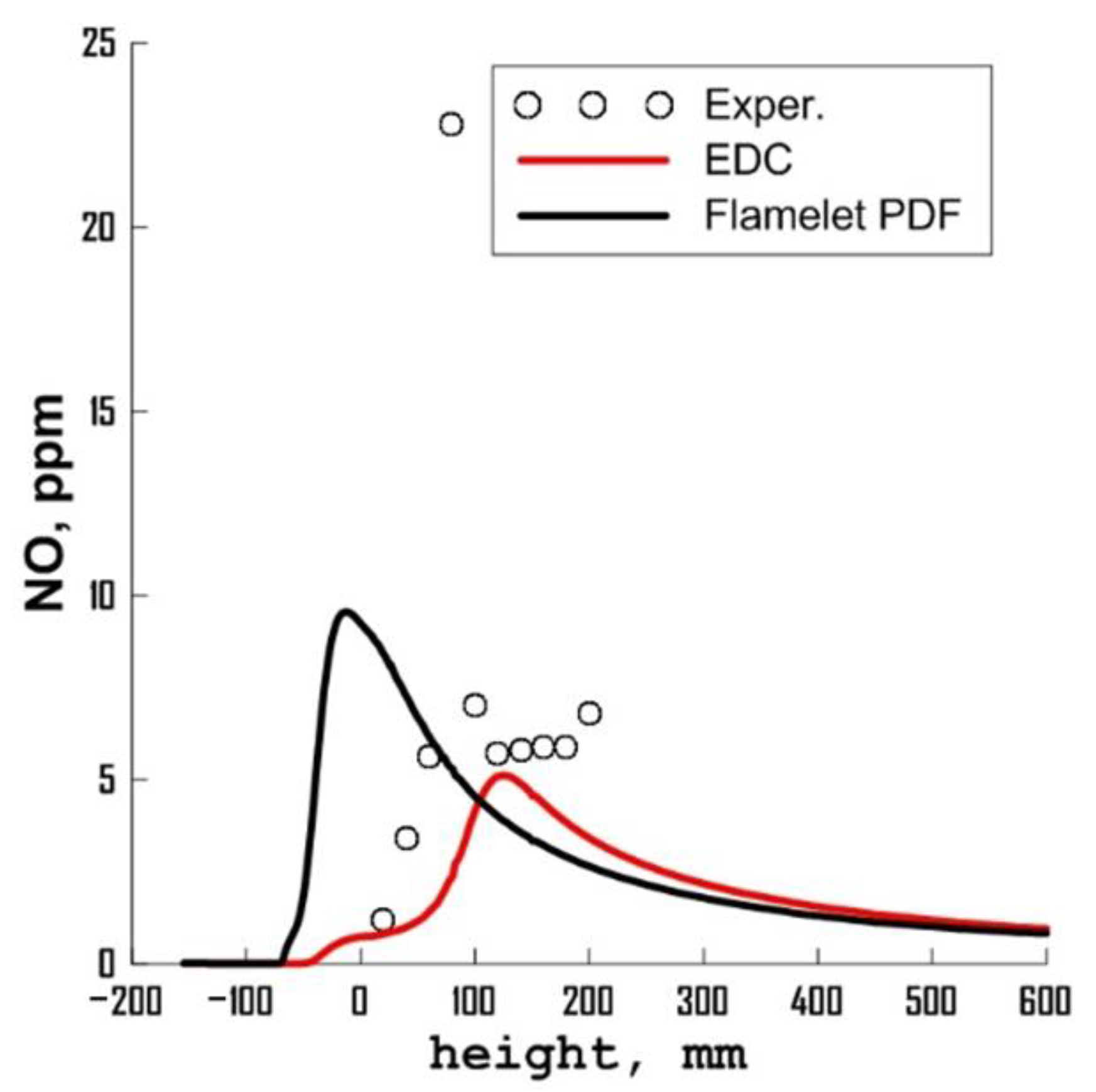
3.2. Influence of the Combustion Model

The simulation results showed the following. The hybrid model, widely used to simulate industrial flames, in this case gave a non-physical flame extinction. It was not possible to obtain stable combustion using this model by any means of initialization.
The EBU model does not take into account the kinetics of chemical reactions, and its reaction rate is limited by the rate of turbulent mixing processes. The calculation results showed that this model gives a qualitatively incorrect shape of the flame, which differs from that observed in the experiment. Obviously, this model cannot be used to simulate such a complex burner.
The computational analysis showed that the best result, other things being equal, can be achieved using the EDC model. A comparison of the EDC model with a multi-stage reaction mechanism and the flamelet PDF model is shown in Figure 11, Figure 12, Figure 13, Figure 14 and Figure 15. The flamelet-PDF model leads to earlier burnout of the fuel, due to which all combustion characteristics are shifted relative to the experiment. The EDC model better describes turbulent combustion and mixing of components during n-heptane combustion with the addition of steam, both qualitatively and quantitatively.

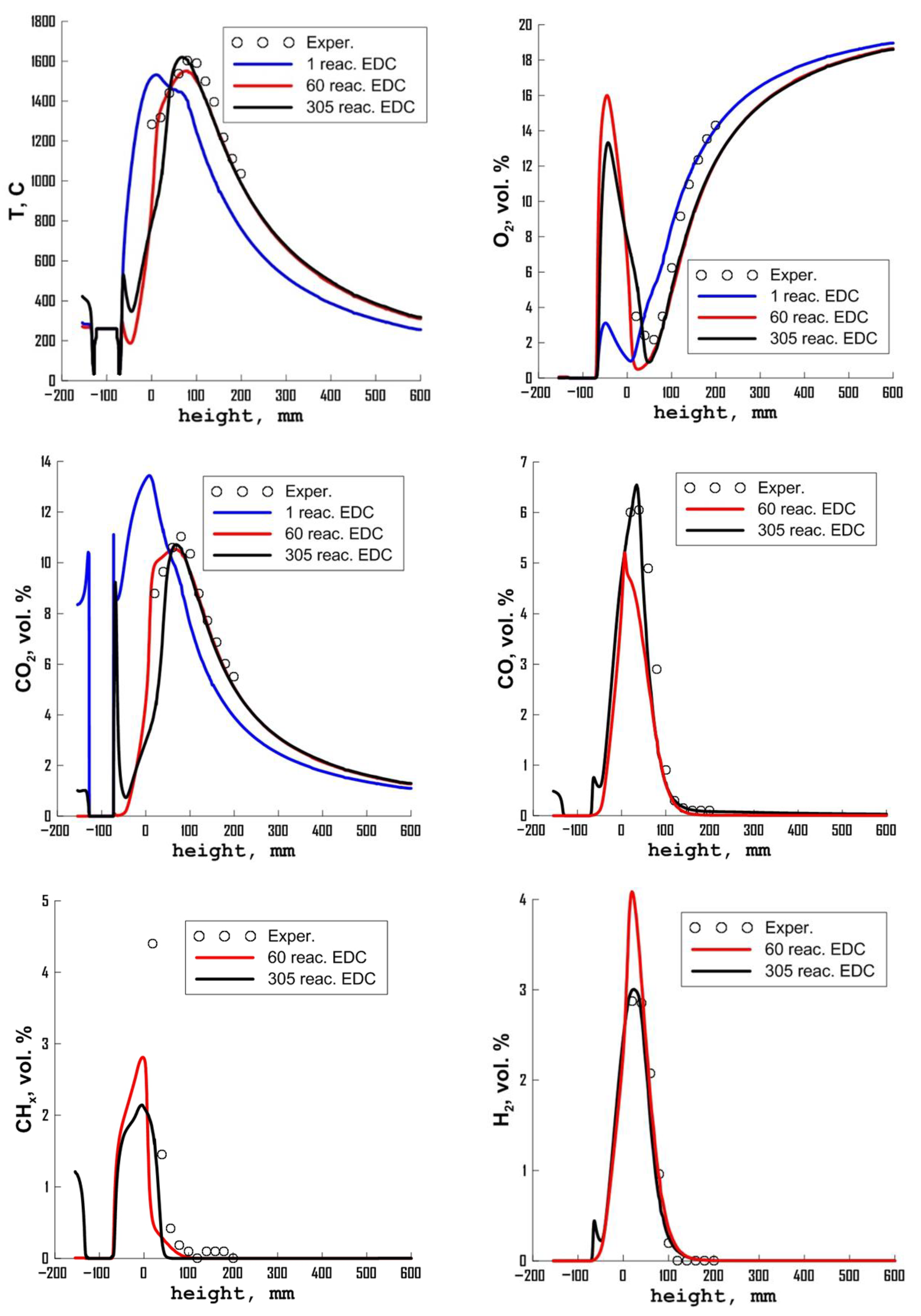
3.3. Influence of Chemical Kinetics Mechanisms

To simulate the kinetics of combustion, mechanisms containing 1, 42, 60, and 305 reactions, were considered. The EDC model was used to simulate the gas phase combustion in these calculations. The k-w SST model was used to simulate turbulence. The simulation results are shown in Figure 16, Figure 17, Figure 18, Figure 19, Figure 20 and Figure 21. Simulation analysis shows that the detailing of the mechanism of chemical kinetics of n-heptane oxidation also turns out to be a significant factor affecting the accuracy of simulation of fuel combustion processes in steam. Thus, it was shown that mechanisms with a small number of reactions describe the combustion process unsatisfactorily. This is most pronounced in terms of oxygen concentration (see Figure 18). The model with one global reaction leads to complete consumption of oxygen inside the burner. This leads to a significant shift in the ignition and combustion processes inside the burner. With an increase in the number of reactions, this defect decreases gradually.
A quantitative comparison of simulation results with experiment is presented in Figure 21. As can be seen, the best agreement with the experiment can be achieved using the most detailed considered mechanism, which includes 305 reactions. This is especially clearly shown in distributions of CO and H2 concentrations. Here, the combination of the EDC combustion model and detailed chemical kinetics gave the lowest calculation error in comparison with the experiment. It should be noted that, in general, very good agreement between calculation and experiment was obtained for such a complex burner. Despite the fact that the mechanism of 305 reactions most accurately describes the reaction of n-heptane in a steam-air mixture; from a practical point of view, it is quite possible to use the mechanism of 60 reactions for simulation. This mechanism gives similar results, but it is much more efficient in terms of counting time than the mechanism of 305 reactions. Other things being equal, the calculation time for the problem with these mechanisms differs by the factor of 8.
It is necessary to note separately the results of simulation with a mechanism consisting of 42 reactions. Calculations with this chemical mechanism with other things being equal were accompanied by flame extinction. Even initialization of calculation with the help of a stable stationary flame obtained by other mechanisms did not give any results. The flame gradually went out completely. Thus, it was shown that the mechanism of chemical kinetics is important not only for the quantitative description of the combustion process, but can also give an incorrect solution even at a qualitative level. Therefore, the mechanism of chemical kinetics for each specific combustion task and burner should be chosen carefully.

3.4. Influence of Radiation Model

When simulating the combustion processes, in addition to the factors studied above, the reliability of simulation is significantly affected by a consideration of radiative heat transfer. In this study, we considered two most common approximations for modeling radiative heat transfer. The P1 method is based on the expansion of intensity into spherical harmonics and takes into account only the first four terms of this expansion in the radiative flux. This model is simple and very efficient in terms of calculation rate as it requires the solution to one additional diffusion transport equation. A more general approach is the discrete ordinate method. In this method, the radiation transfer equation is solved along the rays emitted from each point of the computational domain. For sufficient detail, it is necessary to calculate a large number of rays from each computational cell in all directions. This makes this model rather expensive in terms of computation time. In this study, 64 rays from each cell of the computational domain were used to discretize radiative transfer. The graphs in Figure 22 show a comparison with experiments of the calculation data obtained using various models of radiative transfer. As can be seen, in general, the DO model better reproduces the experimental data. This is especially noticeable for concentration of nitrogen oxides, which is very sensitive to temperature changes. It is shown that the P1 model underestimates NO concentration almost twice.

4. Conclusions

A numerical method was developed for describing the processes of n-heptane combustion in a jet of superheated steam as a promising chemical engineering method for the disposal of substandard liquid fuels and combustible waste with the production of thermal energy. A systematic study was carried out of the influence of turbulence models, models of radiative heat transfer, models of gas-phase reaction and mechanisms of chemical kinetics on the reliability of the description of local and integral characteristics of the reacting flow in the burner.
1. It was shown that the choice of the turbulence model in general does not significantly affect the reliability of the description of the considered turbulent flame, in comparison with other modeling techniques. The best results were obtained using the RSM turbulence model.
2. The best agreement with experiment was obtained using the EDC model. The EBU model gives a qualitatively irregular flame shape, which differs from that observed in the experiment. When using a hybrid model, a non-physical carryover of the flame occurs.
3. With increasing detailing of the mechanism of chemical kinetics, the degree of agreement with experiment becomes better. The best results were obtained using a mechanism consisting of 60 components and 305 elementary reactions. For this problem, a mechanism with 60 reactions turned out to be optimal. This mechanism is slightly inferior to the mechanism of 305 reactions in terms of accuracy, but at the same time it is eight times more economical.
4. The study of the effect of radiation transfer models on the simulation accuracy of the combustion process showed that the DO model describes the experimental data much better than the P1 model, which underestimates the NO concentration by almost two times.
In general, the results of the work showed that despite significant progress in the field of modeling turbulent combustion and existence of a large number of various submodels, their choice for each specific combustion task and burner design should be very careful. Not only does the accuracy of the quantitative description of the combustion process depend on this choice, but qualitatively incorrect results can be also obtained. Therefore, systematic methodical calculations to analyze the influence of combustion submodels in such problems are extremely important and relevant.
The results of systematic testing of gas combustion technologies can be used in the development of new burners and fuel combustion technologies with reduced emissions of harmful substances. To date, the design of burner equipment is carried out using numerical simulation. However, the issue of choosing a large set of submodels remains very relevant. The results obtained in this work will help engineers and equipment designers to make a better choice of models for the correct description of fuel combustion processes. In the present work, the influence of combustion submodels on the accuracy of the description of a direct-flow flame is studied. However, in practice, many burners operate with swirling flow. Simulation of a swirling flame can differ significantly from that of a direct-flow flame. In swirling flows, a number of complex phenomena may occur, such as precession of the vortex core or flame breakthrough. To simulate these phenomena, it is necessary to use eddy-resolving turbulence models. Therefore, in the future, a detailed systematic study is planned of the effect of combustion and turbulence submodels on swirling flames modelling.

Author Contributions

Conceptualization, A.V.M. and A.A.D.; methodology, A.A.D.; software, V.A.K.; validation, V.A.K. and A.V.M.; formal analysis, A.V.M.; investigation, V.A.K.; writing—original draft preparation, V.A.K. and E.P.K.; writing—review and editing, A.V.M.; visualization, V.A.K. and E.P.K.; supervision, A.V.M.; project administration, S.V.A. and I.S.A.; funding acquisition, S.V.A. and I.S.A. All authors have read and agreed to the published version of the manuscript.

Funding

Computational studies of the combustion of n-heptane in a steam flow in an evaporative burner were funded by the Russian Science Foundation (project No.18-79-10134). The study of the influence of turbulence models, combustion models, and mechanisms of chemical kinetics on the reliability of numerical calculations during the combustion of liquid fuel in a steam flow was funded by the Russian Science Foundation (project No. 19-19-00443).

Institutional Review Board Statement

Not applicable.

Informed Consent Statement

Not applicable.

Data Availability Statement

Not applicable.

Acknowledgments

Not applicable.

Conflicts of Interest

The authors declare no conflict of interest.

References

  1. Fratita, M.; Popescu, F.; Martins, J.; Brito, F.P.; Costa, T. Water Injection as a Way for Pollution Control. Energy Rep. 2021, 7, 543–549. [Google Scholar] [CrossRef]
  2. Alekseenko, S.; Anufriev, I.; Glavniy, V.; Krasinsky, D.; Rakhmanov, V.; Salomatov, V.; Shadrin, E. Study of 3D Flow Structure and Heat Transfer in a Vortex Furnace. Heat Transf. Res. 2016, 47, 653–667. [Google Scholar] [CrossRef]
  3. Amani, E.; Akbari, M.R.; Shahpouri, S. Multi-Objective CFD Optimizations of Water Spray Injection in Gas-Turbine Combustors. Fuel 2018, 227, 267–278. [Google Scholar] [CrossRef]
  4. Da Rocha, D.D.; de Castro Radicchi, F.; Lopes, G.S.; Brunocilla, M.F.; Gomes, P.C.F.; Santos, N.D.S.A.; Malaquias, A.C.T.; Rodrigues Filho, F.A.; Baêta, J.G.C. Study of the Water Injection Control Parameters on Combustion Performance of a Spark-Ignition Engine. Energy 2021, 217, 119346. [Google Scholar] [CrossRef]
  5. Pavri, R.; Moore, G. Gas Turbine Emissions and Control; GE Power Syst.: Atlanta, GA, USA, 2001. [Google Scholar]
  6. Gu, J.; Shao, Y.; Zhong, W. Study on Oxy-Fuel Combustion Behaviors in a S-CO2 CFB by 3D CFD Simulation. Chem. Eng. Sci. 2020, 211, 115262. [Google Scholar] [CrossRef]
  7. Fan, Y.; Wu, T.; Xiao, D.; Xu, H.; Li, X.; Xu, M. Effect of Port Water Injection on the Characteristics of Combustion and Emissions in a Spark Ignition Direct Injection Engine. Fuel 2021, 283, 119271. [Google Scholar] [CrossRef]
  8. Sehat, A.; Ommi, F.; Saboohi, Z. Effects of Steam Addition and/or Injection on the Combustion Characteristics: A Review. Therm. Sci. 2021, 25, 1625–1652. [Google Scholar] [CrossRef] [Green Version]
  9. Li, S.C.; Williams, F.A. NOx Formation in Two-Stage Methane–Air Flames. Combust. Flame 1999, 118, 399–414. [Google Scholar] [CrossRef]
  10. Xue, R.; Hu, C.; Sethi, V.; Nikolaidis, T.; Pilidis, P. Effect of Steam Addition on Gas Turbine Combustor Design and Performance. Appl. Therm. Eng. 2016, 104, 249–257. [Google Scholar] [CrossRef] [Green Version]
  11. Mohapatra, S.; Garnayak, S.; Lee, B.J.; Elbaz, A.M.; Roberts, W.L.; Dash, S.K.; Reddy, V.M. Numerical and Chemical Kinetic Analysis to Evaluate the Effect of Steam Dilution and Pressure on Combustion of N-Dodecane in a Swirling Flow Environment. Fuel 2021, 288, 119710. [Google Scholar] [CrossRef]
  12. Benini, E.; Pandolfo, S.; Zoppellari, S. Reduction of NO Emissions in a Turbojet Combustor by Direct Water/Steam Injection: Numerical and Experimental Assessment. Appl. Therm. Eng. 2009, 29, 3506–3510. [Google Scholar] [CrossRef] [Green Version]
  13. Alekseenko, S.; Anufriev, I.; Vigriyanov, M.; Kopyev, E.; Sadkin, I.; Sharypov, O. Burning of Heavy Fuel Oil in a Steam Jet in a New Burner. J. Appl. Mech. Tech. Phys. 2020, 61, 324–330. [Google Scholar] [CrossRef]
  14. Anufriev, I.; Kovyev, E.; Alekseenko, S.; Sharypov, O.; Butakov, E.; Vigriyanov, M.; Sadkin, I. Cleaner Crude Oil Combustion during Superheated Steam Atomization. Therm. Sci. 2021, 25, 331–345. [Google Scholar] [CrossRef]
  15. Anufriev, I.; Kopyev, E.; Sadkin, I.; Mukhina, M. Diesel and Waste Oil Combustion in a New Steam Burner with Low NOX Emission. Fuel 2021, 290, 120100. [Google Scholar] [CrossRef]
  16. Anufriev, I.; Kopyev, E. Diesel Fuel Combustion by Spraying in a Superheated Steam Jet. Fuel Process. Technol. 2019, 192, 154–169. [Google Scholar] [CrossRef]
  17. Anufriev, I.; Alekseenko, S.; Sharypov, O.; Kopyev, E. Diesel Fuel Combustion in a Direct-Flow Evaporative Burner with Superheated Steam Supply. Fuel 2019, 254, 115723. [Google Scholar] [CrossRef]
  18. Anufriev, I.; Kopyev, E.; Sadkin, I.; Mukhina, M. NOx Reduction by Steam Injection Method during Liquid Fuel and Waste Burning. Process Saf. Environ. Prot. 2021, 152, 240–248. [Google Scholar] [CrossRef]
  19. Alekseenko, S.; Pashchenko, S.; Salomatov, V. Nanocluster Initiation of Combustion of Off-Grade Hydrocarbon Fuels. J. Eng. Phys. Thermophys. 2010, 83, 729–741. [Google Scholar] [CrossRef]
  20. Kopyev, E.; Anufriev, I.; Mukhina, M.; Sadkin, I. Combustion of Kerosene Sprayed with a Jet of Superheated Steam. J. Phys. Conf. Ser. 2021, 2119, 012040. [Google Scholar] [CrossRef]
  21. Alekseenko, S.; Kuznetsov, V.; Mal’tsev, L.; Dekterev, A.; Chernetskii, M. Analysis of Combustion of Coal-Water Fuel in Low-Power Hot-Water Boiler via Numerical Modeling and Experiments. J. Eng. Thermophys. 2019, 28, 177–189. [Google Scholar] [CrossRef]
  22. Lobasov, A.; Dekterev, A.; Minakov, A. Numerical Simulation of Premixed Methane/Air and Synthesis Gas/Air Flames for Turbulence Swirling Jet. J. Phys. Conf. Ser. 2019, 1382, 012060. [Google Scholar] [CrossRef]
  23. Dekterev, A.; Kuznetsov, V. Investigation of Pulverized Coal Flaring Based on Eddy-Resolving Turbulence Models. J. Phys. Conf. Ser. 2020, 1677, 012104. [Google Scholar] [CrossRef]
  24. Dulin, V.; Markovich, D.; Minakov, A.; Hanjalic, K.; Chikishev, L. Experimental and Numerical Simulation for Swirl Flow in a Combustor. Therm. Eng. 2013, 60, 990–997. [Google Scholar] [CrossRef]
  25. Nooren, P.A.; Wouters, H.A.; Peeters, T.W.J.; Roekaerts, D.; Maas, U.; Schmidt, D. Monte Carlo PDF Modelling of a Turbulent Natural-Gas Diffusion Flame. Combust. Theory Model. 2010, 1, 79–96. [Google Scholar] [CrossRef]
  26. Celis, C.; Figueira Da Silva, L.F. Lagrangian Mixing Models for Turbulent Combustion: Review and Prospects. Flow, Turbul. Combust. 2015 943 2015, 94, 643–689. [Google Scholar] [CrossRef]
  27. Lysenko, D.A.; Ertesvåg, I.S.; Kjell, R.E.; Rian, E.; Lysenko, D.A.; Ertesvåg, I.S.; Rian, K.E. Numerical Simulations of the Sandia Flame D Using the Eddy Dissipation Concept. Flow Turbul. Combust. 2014, 93, 665–687. [Google Scholar] [CrossRef]
  28. Trisjono, P.; Kleinheinz, K.; Pitsch, H.; Kang, S. Large Eddy Simulation of Stratified and Sheared Flames of a Premixed Turbulent Stratified Flame Burner Using a Flamelet Model with Heat Loss. Flow Turbul. Combust. 2013, 92, 201–235. [Google Scholar] [CrossRef]
  29. Wang, G.; Boileau, M.; Veynante, D. Implementation of a Dynamic Thickened Flame Model for Large Eddy Simulations of Turbulent Premixed Combustion. Combust. Flame 2011, 158, 2199–2213. [Google Scholar] [CrossRef]
  30. Schmitt, T.; Sadiki, A.; Fiorina, B.; Veynante, D. Impact of Dynamic Wrinkling Model on the Prediction Accuracy Using the F-TACLES Combustion Model in Swirling Premixed Turbulent Flames. Proc. Combust. Inst. 2013, 34, 1261–1268. [Google Scholar] [CrossRef]
  31. Kuenne, G.; Seffrin, F.; Fuest, F.; Stahler, T.; Ketelheun, A.; Geyer, D.; Janicka, J.; Dreizler, A. Experimental and Numerical Analysis of a Lean Premixed Stratified Burner Using 1D Raman/Rayleigh Scattering and Large Eddy Simulation. Combust. Flame 2012, 159, 2669–2689. [Google Scholar] [CrossRef]
  32. Mercier, R.; Auzillon, P.; Moureau, V.; Darabiha, N.; Gicquel, O.; Veynante, D.; Fiorina, B. LES Modeling of the Impact of Heat Losses and Differential Diffusion on Turbulent Stratified Flame Propagation: Application to the TU Darmstadt Stratified Flame. Flow Turbul. Combust. 2014, 93, 349–381. [Google Scholar] [CrossRef]
  33. Sabelnikov, V.; Fureby, C. Extended LES-PaSR Model for Simulation of Turbulent Combustion. Prog. Propuls. Phys. 2013, 4, 539–568. [Google Scholar] [CrossRef] [Green Version]
  34. Moureau, V.; Domingo, P.; Vervisch, L. Design of a Massively Parallel CFD Code for Complex Geometries. Comptes Rendus Mécanique 2011, 339, 141–148. [Google Scholar] [CrossRef]
  35. Ge, H.W.; Duwel, I.; Kronemayer, H.; Dibble, R.W.; Gutheil, E.; Schulz, C.; Wolfrum, J. Laser-Based Experimental and Monte Carlo PDF Numerical Investigation of an Ethanol/Air Spray Flame. Combust. Sci. Technol. 2008, 180, 1529–1547. [Google Scholar] [CrossRef]
  36. Peters, N. Laminar Diffusion Flamelet Models in Non-Premixed Turbulent Combustion. Prog. Energy Combust. Sci. 1984, 10, 319–339. [Google Scholar] [CrossRef]
  37. Lemaire, R.; Faccinetto, A.; Therssen, E.; Ziskind, M.; Focsa, C.; Desgroux, P. Experimental Comparison of Soot Formation in Turbulent Flames of Diesel and Surrogate Diesel Fuels. Proc. Combust. Inst. 2009, 32, 737–744. [Google Scholar] [CrossRef]
  38. Zhang, K.; Xin, Q.; Mu, Z.; Niu, Z.; Wang, Z. Numerical Simulation of Diesel Combustion Based on N-Heptane and Toluene. Propuls. Power Res. 2019, 8, 121–127. [Google Scholar] [CrossRef]
  39. Pitz, W.J.; Mueller, C.J. Recent Progress in the Development of Diesel Surrogate Fuels. Prog. Energy Combust. Sci. 2011, 37, 330–350. [Google Scholar] [CrossRef] [Green Version]
  40. Liang, X.; Ju, D.; Han, D. Numerical Study on the Physical and Chemical Processes in N-Decane Spray Ignition. Chem. Eng. Sci. 2021, 241, 116716. [Google Scholar] [CrossRef]
  41. Kolaitis, D.I.; Founti, M.A. On the Assumption of Using N-Heptane as a “Surrogate Fuel” for the Description of the Cool Flame Oxidation of Diesel Oil. Proc. Combust. Inst. 2009, 32, 3197–3205. [Google Scholar] [CrossRef]
  42. Minakov, A.; Anufriev, I.; Kuznetsov, V.; Dekterev, A.; Kopyev, E.; Sharypov, O. Combustion of Liquid Hydrocarbon Fuel in an Evaporative Burner with Forced Supply of Superheated Steam and Air to the Reaction Zone. Fuel 2022, 309, 122181. [Google Scholar] [CrossRef]
  43. Alekseenko, S.; Anufriev, I.; Vigriyanov, M.; Kopyev, E.; Sharypov, O. Characteristics of Diesel Fuel Combustion in a Burner with Injection of a Superheated Steam Jet. Combust. Explos. Shock Waves 2016, 52, 286–293. [Google Scholar] [CrossRef]
  44. Alekseenko, S.; Anufriev, I.; Arsentyev, S.; Vigriyanov, M.; Kopyev, E.; Sharypov, O. Influence of Parameters of Superheated Steam on Combustion of Liquid Hydrocarbons. Thermophys. Aeromech. 2019, 26, 103–107. [Google Scholar] [CrossRef]
  45. Minakov, A.; Kuznetsov, V.; Anufriev, I.; Kopyev, E. Numerical Analysis of a Pre-Chamber Vortex Burner with a Steam Blast Atomizer. Fuel 2022, 323, 124375. [Google Scholar] [CrossRef]
  46. Launder, B.E.; Spalding, D.B. Lectures in Mathematical Models of Turbulence; Academic Press: London, UK, 1972. [Google Scholar]
  47. Smirnov, P.E.; Menter, F.R. Sensitization of the SST Turbulence Model to Rotation and Curvature by Applying the Spalart-Shur Correction Term. J. Turbomach. 2009, 131, 1–8. [Google Scholar] [CrossRef]
  48. Menter, F. Zonal Two Equation K-w Turbulence Models For Aerodynamic Flows. In Proceedings of the 23rd Fluid Dynamics, Plasmadynamics, and Lasers Conference; American Institute of Aeronautics and Astronautics: Reston, Virigina, Orlando, FL, USA, 6–9 July 1993; p. 2906. [Google Scholar]
  49. Daly, B.J.; Harlow, F.H. Transport Equations in Turbulence. Phys. Fluids 2003, 13, 2634. [Google Scholar] [CrossRef]
  50. Launder, B.E.; Reece, G.J.; Rodi, W. Progress in the Development of a Reynolds-Stress Turbulence Closure. J. Fluid Mech. 1975, 68, 537–566. [Google Scholar] [CrossRef] [Green Version]
  51. Spalding, D.B. Mixing and Chemical Reaction in Steady Confined Turbulent Flames. Symp. Combust. 1971, 13, 649–657. [Google Scholar] [CrossRef]
  52. Magnussen, B.F.; Hjertager, B.H. On Mathematical Modeling of Turbulent Combustion with Special Emphasis on Soot Formation and Combustion. Symp. Combust. 1977, 16, 719–729. [Google Scholar] [CrossRef]
  53. Magnussen, B. On the Structure of Turbulence and a Generalized Eddy Dissipation Concept for Chemical Reaction in Turbulent Flow. In Proceedings of the 19th Aerospace Sciences Meeting; American Institute of Aeronautics and Astronautics, Reston, VA, USA, 12 January 1981. [Google Scholar] [CrossRef]
  54. Raithby, G.D.; Chui, E.H. A Finite-Volume Method for Predicting a Radiant Heat Transfer in Enclosures With Participating Media. J. Heat Transfer 1990, 112, 415–423. [Google Scholar] [CrossRef]
  55. Cheng, P. Two-Dimensional Radiating Gas Flow by a Moment Method. AIAA J. 1964, 2, 1662–1664. [Google Scholar] [CrossRef]
  56. Howell, J.R.; Menguc, M.P.; Siegel, R. Thermal Radiation Heat Transfer. Therm. Radiat. Heat Transf. 2010, 93, 17522. [Google Scholar] [CrossRef] [Green Version]
  57. Patel, A.; Kong, S.C.; Reitz, R.D. Development and Validation of a Reduced Reaction Mechanism for HCCI Engine Simulations. In Proceedings of the SAE 2004 World Congress & Exhibition, Detroit, MI, USA, 8–11 March 2004. [Google Scholar] [CrossRef]
  58. UC San Diego Website. Chemical-Kinetic Mechanisms for Combustion Applications: Heptane Chemistry. Available online: https://web.eng.ucsd.edu/mae/groups/combustion/mechanism.html (accessed on 17 December 2022).
  59. Hiroyasu, H.; Kadota, T. Models for Combustion and Formation of Nitric Oxide and Soot in Direct Injection Diesel Engines. In Proceedings of the 1976 Automotive Engineering Congress and Exposition, Detroit, MI, USA, 23–27 February 1976; p. 760129. [Google Scholar] [CrossRef]
  60. Nagle, J.; Strickland-Constable, R.F. Oxidation Of Carbon between 1000–2000 °C. In Proceedings of the Fifth Conference on Carbon; Macmillan: New York, NY, USA, 1962; pp. 154–164. [Google Scholar] [CrossRef]
  61. Zeldovich, Y.A.; Frank-Kamenetskii, D.; Sadovnikov, P. Oxidation of Nitrogen in Combustion; Publishing House of the Acad of Sciences of USSR: Moscow, Russia, 1947. [Google Scholar]
  62. De Soete, G.G. Overall Reaction Rates of NO and N2 Formation from Fuel Nitrogen. Symp. Combust. 1975, 15, 1093–1102. [Google Scholar] [CrossRef]
Figure 1. Heptane combustion in the experimental burner.
Energies 16 00025 g001
Figure 2. Scheme of the processes in the evaporation burner.
Energies 16 00025 g002
Figure 3. Geometry of computation domain: (a) full; (b) in the form of a sector.
Energies 16 00025 g003
Figure 4. Comparison of the calculation results obtained for different grid sizes.
Energies 16 00025 g004
Figure 5. Streamlines, m/s (limited by the value of 20 m/s): (a) k-e; (b) k-w SST; (c) RSM.
Energies 16 00025 g005
Figure 6. Temperature in the burnet and at its outlet, °C: (a) k-e; (b) k-w SST; (c) RSM.
Energies 16 00025 g006
Figure 7. Volume fraction of O2: (a) k-e; (b) k-w SST; (c) RSM.
Energies 16 00025 g007
Figure 8. Volume fraction of C7H16: (a) k-e; (b) k-w SST; (c) RSM.
Energies 16 00025 g008
Figure 9. Concentration of nitrogen oxides, ppm: (a) k-e; (b) k-w SST; (c) RSM.
Energies 16 00025 g009
Figure 10. Distribution of temperature and gas composition along the burner axis in the experiment and the calculation for various turbulence models.
Energies 16 00025 g010aEnergies 16 00025 g010b
Figure 11. Streamlines, m/s (limited by the value of 20 m/s): (a) EDC; (b) Flamelet-PDF.
Energies 16 00025 g011
Figure 12. Temperature in the burner and at its outlet, °C: (a) EDC; (b) Flamelet-PDF.
Energies 16 00025 g012
Figure 13. Volume fraction of C7H16: (a) EDC; (b) Flamelet-PDF.
Energies 16 00025 g013
Figure 14. Concentration of NOx: (a) EDC; (b) Flamelet-PDF.
Energies 16 00025 g014
Figure 15. Distribution of temperature and gas composition along the burner axis in experiment and calculation for various combustion models.
Energies 16 00025 g015aEnergies 16 00025 g015b
Figure 16. Streamlines, m/s (limited by the value of 20 m/s): (a) 1 reaction EDC; (b) 60 reactions EDC; (c) 305 reactions EDC.
Energies 16 00025 g016
Figure 17. Temperature in the burner and at its outlet, °C: (a) 1 reaction EDC; (b) 60 reactions EDC; (c) 305 reactions EDC.
Energies 16 00025 g017
Figure 18. Volume fraction of O2: (a) 1 reaction EDC; (b) 60 reactions EDC; (c) 305 reactions EDC.
Energies 16 00025 g018
Figure 19. Volume fraction of C7H16: (a) 1 reaction EDC; (b) 60 reactions EDC; (c) 305 reactions EDC.
Energies 16 00025 g019
Figure 20. Concentration of NOx: (a) 1 reaction EDC; (b) 60 reactions EDC; (c) 305 reactions EDC.
Energies 16 00025 g020
Figure 21. Distribution of temperature and gas composition along the burner axis in the experiment and the calculation for various mechanisms of chemical kinetics.
Energies 16 00025 g021aEnergies 16 00025 g021b
Figure 22. Distribution of temperature and gas composition along the burner axis in experiment and calculation for different radiation models.
Energies 16 00025 g022aEnergies 16 00025 g022b
Table 1. Properties and chemical composition of n-Heptane.
ParameterValue
Density (kg/m3)684
Viscosity (cSt)0.6
Low heat value (MJ/kg)48.6
High heat value qf (MJ/kg)45.0
C (% w/w)84
H (% w/w)16
Table 2. Global 1-stage mechanism.
ReactionA [kg/(m2sPa)]E, J/kmolβComponents Degree γ
nC7H16+11O2 = 7CO2+8H2O2.86∙1091.256∙1080γCH4 = 0.25, γO2 = 1.5
Disclaimer/Publisher’s Note: The statements, opinions and data contained in all publications are solely those of the individual author(s) and contributor(s) and not of MDPI and/or the editor(s). MDPI and/or the editor(s) disclaim responsibility for any injury to people or property resulting from any ideas, methods, instructions or products referred to in the content.

