Article

Analysis of Fault Characteristics of Distribution Network with PST Loop Closing Device under Small Current Grounding System

1
Electric Power Research Institute, Yunnan Power Grid Co., Ltd., Kunming 650217, China
2
State Key Laboratory of Alternate Electrical Power System with Renewable Energy Sources, North China Electric Power University, Baoding 071003, China
3
Yunnan Power Grid Co., Ltd., Kunming Power Supply Bureau, Kunming 650032, China
*
Author to whom correspondence should be addressed.
Energies 2022, 15(7), 2307; https://doi.org/10.3390/en15072307
Submission received: 27 February 2022 / Revised: 17 March 2022 / Accepted: 19 March 2022 / Published: 22 March 2022
(This article belongs to the Topic Power Distribution Systems)

Abstract

:
With the rapid development of cities and the increasing complexity of distribution network systems, the cableization of transmission lines and the diversification of power users have brought new challenges to the supply reliability of distribution networks. Short-time outages caused by power outages and maintenance are one of the factors that affect the reliability of the power supply in the distribution network. The non-stop load transfer through a phase-shifting transformer (PST) operation can effectively improve the reliability of power supply to complex distribution systems. Considering the operation mode and structure form and fault type of the urban distribution network in China, comparing and analyzing the applicable scenarios of different neutral grounding methods, and based on the structure and zero sequence path characteristics of PST, an improved PST-based phase shifting and grounding transformer loop closing device with low power consumption is proposed. The fault characteristics of the PST-based loop closing device under the small current grounding system are also analyzed by the sequence component method, and, finally, the effectiveness of the phase-shifting and grounding transformer device is verified by simulation under PSCAD/EMTDC for fault routing and protection configuration of the urban distribution network in China.

1. Introduction

At present, China’s 10 kV distribution system is mainly based on neutral point ungrounding and grounding via arc extinguishing coil [1,2]. With the cableization of transmission lines, increasing network density, and diversification of power users in urban distribution networks, the ground capacitance current of distribution networks has increased substantially [3,4]. Faults such as cable head explosion and damage to power equipment due to overvoltage caused by arc grounding occur from time to time [5]. Inaccurate and untimely troubleshooting leads to protection rejection and misoperation, the consequences of which have a serious impact on power supply reliability.
In order to cope with the problems caused by urban development and cableization of distribution systems and to be able to eliminate line faults occurring in distribution systems in a timely and accurate manner, cities such as Beijing, Shanghai, and Shenzhen, where the cableization rate of distribution systems is high, have changed the neutral point ungrounded and neutral point grounded by arc extinguishing coil to neutral point grounded by small resistance [6,7]. The neutral point via the small resistance grounding method can effectively limit the arc grounding overvoltage as well as the advantages of accurate and timely removal of the faulty line [8]. Although the protection of overhead lines with a neutral point grounded by small resistance will act to trip for the occurrence of transient faults or permanent faults, which affects the reliability of power supply to a certain extent [9], the probability of single-phase transient faults in cables is relatively small in distribution systems with high capacitive currents and mainly cable transmission lines. Most of the single-phase grounding faults occurring in the cable are permanent faults, so the neutral point via the small resistance grounding method in the distribution system with a high cableization rate can cope well with problems such as arc grounding overvoltage and excessive capacitive current.
Whether the neutral point is grounded via the arc extinguishing coil or via the small resistance grounding method requires the distribution system to provide a groundable neutral point. However, in order to balance the third harmonic flux generated by the non-linearity of the transformer core, the distribution system generally connects the transformer low-voltage windings into triangles [10], which means that the 10 kV side of the transformer in the distribution system is wired in triangles without a direct neutral point. For neutral grounding, a grounding transformer can be connected to introduce an artificial grounding point on the 10 kV side of the transformer. Because Z-type grounding transformers have the advantages of high impedance for positive and negative sequence currents, low impedance for zero sequence currents, and small excitation currents in the windings, Z-type grounding transformers are usually used [11]. The literature [12] summarizes four options for grounding transformer and small resistor connection to the system, which are connected separately at the outlet of the low voltage side of the main transformer, separately at the outlet side of the low voltage side of the main transformer, directly at the neutral point of the low voltage side of the transformer with balanced winding and grounding transformer and station transformer connection.
Based on the structural form and operation mode characteristics of China’s distribution network, the non-stop load reversal through the loop operation can reduce the outage time, improve the reliability of power supply, ensure the quality of system power supply, and improve the public satisfaction of power services [13,14]. The phase-shifting transformer (PST) based loop closing device has the characteristics of a flexible and wide range of regulation, outstanding cost advantage, and easy operation and maintenance [15], but it is mainly put into the distribution network system for the function of loop closing transfer. Combining the structural characteristics of Y-type wiring on the primary side of PST and the grounding transformer and small resistance connection, this paper proposed a phase-shifting and grounding transformer (PSGT) device with a neutral point grounded by small resistance. Based on the original structure and functions of PST, the PSGT with small resistance grounding at a neutral point can not only realize the phase-shifting function required for the loop to supply, but also solve the arc-earth overvoltage problem and improve the power supply reliability of the distribution system mainly for cable lines.
This paper firstly introduces the ring-closing scenario of a 10 kV distribution system and analyzes the working principle and application scenario based on the PST loop closing device. Secondly, the distribution network introduction grounding transformer method is analyzed. Based on the structural characteristics of the PST loop closing device and the fault characteristics of the distribution network, the characteristics of the traditional mechanical loop closing device and the loop closing device based on modern power electronics technology are compared and analyzed, and the PSGT device with a neutral point grounded by small resistance is proposed. In addition, based on the zero-sequence loop characteristics of PSGT, its structure is improved to have a zero-sequence current path, and then the fault characteristics of the PST-based loop closing device under a small current grounding system are analyzed. The proposed PSGT with a neutral point grounded by small resistance is verified in the PSCAD/EMTDC environment.

2. Materials and Methods

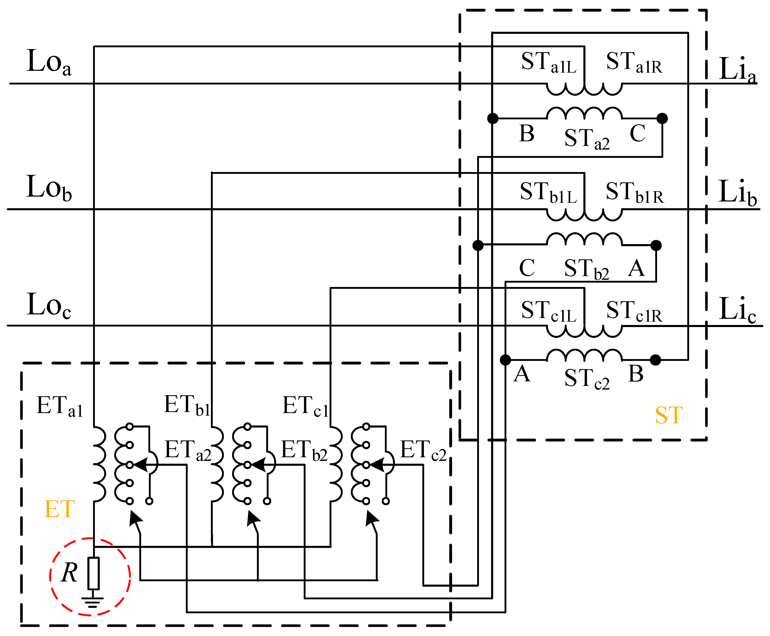
2.1. Introduction Method of an Additional Neutral Point

With the rapid development of the city, the proportion of cable lines is also increasing, the capacitance current is also getting larger and larger, the occurrence of single-phase faults without timely action tripping can result in cable burn in the distribution network of the entire cable burn or even develop into more serious consequences of inter-phase faults [16]. Therefore, in order to ensure the accuracy and timeliness of fault removal and improve the reliability of the power supply in the distribution system, the neutral point of the distribution system is grounded via small resistance. The neutral point grounded via small resistance has many advantages such as being able to effectively limit the arcing ground overvoltage as well as being able to remove the faulty line in time [17].
However, in urban distribution network substations, for balanced third harmonic flux, due to the non-linearity of the transformer core, the transformer 10 kV side is generally triangular wiring without a grounding point lead [18]. To achieve the neutral point by small resistance grounding, the grounding transformer can be configured to introduce an additional grounding point. Single-phase grounding occurs when the fault current through the neutral point of the grounding transformer and the fault grounding point can form an effective zero-sequence path, grounding change and fault lines have zero-sequence current flow, providing timely action and protection [19]. However, when a single-phase ground fault occurs inside the grounding transformer or related lead wires, the grounding transformer protection is unable to quickly jump open the switch on that side and accurately isolate the fault, causing a loss of voltage in the 10 kV bus and expanding the outage range [20]. The State grid has corresponding calibration standards for feeder protection and grounding transformer protection, but there is a lack of coordination between the grounding transformer and feeder protection, which may cause an incorrect operation of the relay protection and affect the safe operation of the grid. Therefore, the protection calibration of the grounding transformer and feeder protection needs to be improved appropriately [21]. In order to make sure that the grounding change protection under the above fault conditions can be quickly and accurately identified and the primary fault isolated, the outage range reduced and personal safety ensured, appropriate zero-sequence differential protection should be set.

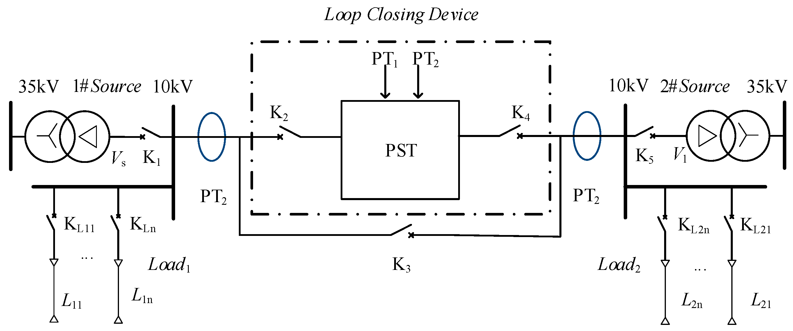
2.2. PST-Based Loop Closing Transfer Device

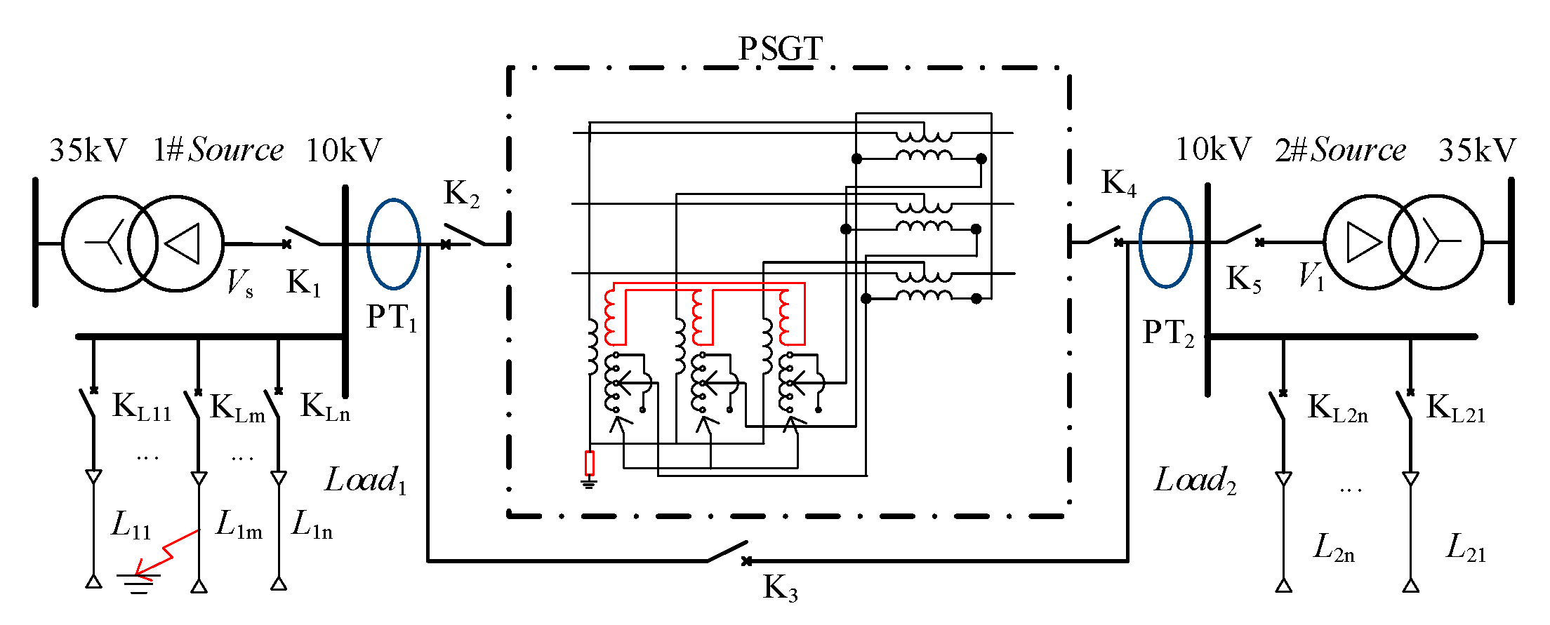
2.2.1. Loop Closing Transfer Scenario

With the increasing requirements of power users for power quality and supply reliability, better meeting the needs of power users has become one of the goals of distribution network optimization development, and at this stage, closed-loop design and open-loop operation are commonly implemented in China’s distribution networks. With the increasing requirements of power users, the network structure is becoming more and more complex, and it is an inevitable trend to realize non-stop load reversal through a loop closing operation in order to improve power quality and power supply reliability [22]. As the distribution network structure becomes more and more complex, the actual bus parameters on both sides of the loop operation are difficult to meet the loop conditions, and the frequency difference in the distribution network is generally not large, and the loop conditions are mainly influenced by the voltage magnitude difference on both sides of the loop point. The distribution network in China allows for the loop operation under the conditions of “consistent phase sequence, voltage magnitude difference less than 20% on both sides of the loop point, and phase angle difference less than 5°” [23]. At this stage, the actual loop closing operation is also based on the above conditions to judge the loop closing operation and then realize a smaller inrush current loop closing transfer.
How to realize the loop closing non-stop transfer of supply has become a hot research topic, but the grid often does not meet the loop closing conditions in actual operation, so efficient and safe non-stop load transfer requires the study of new loop closing device technology. Ye Q et al. [24] controlled system currents by adjusting transformer taps and using reactive power compensation, but could not adjust the phase difference between voltages, making it difficult to achieve long-term stable loop closing operation of multiple power sources. Zhang Z et al. [25] proposed a control strategy to optimize the loop closing currents by applying a unified tide controller, taking into account the distribution network loss and node voltage deviation. Li S et al. [26] proposed to find the two nodes with the minimum voltage difference as the optimal closing point in the distribution network by using merit search, but the ring network location and operation mode are changed, and the distribution network structure will be changed as a result. Zhao C et al. [27] analyzed the countermeasures to reduce the closing current during the closing operation, and developed the corresponding closing operation means with less impact on relay protection measures. Chen G et al. [28] analyzed the risks of low-voltage loop closing and the causes of loop closing currents through simulation and proposed operational suggestions for loop closing and power transfer to ensure the safety and reliability of low-voltage loop closing operation, which provided some theoretical and technical support for low-voltage loop closing to realize non-stop power transfer. PST is mainly used for voltage phase regulation by changing the tap, and the PST technology is relatively mature and relatively easy to operate and maintain [29], so it is considered to be applied as a loop closing device for loop closing transfer. The application scenario of PST as a loop closing device is shown in Figure 1.
The dual power distribution system in Figure 1 is the same 35 kV transformer to 10 kV, and the two buses are equipped with a closing loop device based on a phase-shifting transformer. K1 to K5 are closing switches, KCn and KLn (n = 1, 2, 3, ...) are protection switches for cable lines and overhead lines respectively. The voltage amplitude and voltage phase of the regulated object is detected by the voltage detection elements PT1 and PT2. The measured parameters are transmitted to the PST by the control element. Through the PST phase shift adjustment to achieve the loop closure switch to meet the loop closing adjustment, different switch combinations cooperate with each other to complete the input and exit loop closing device.

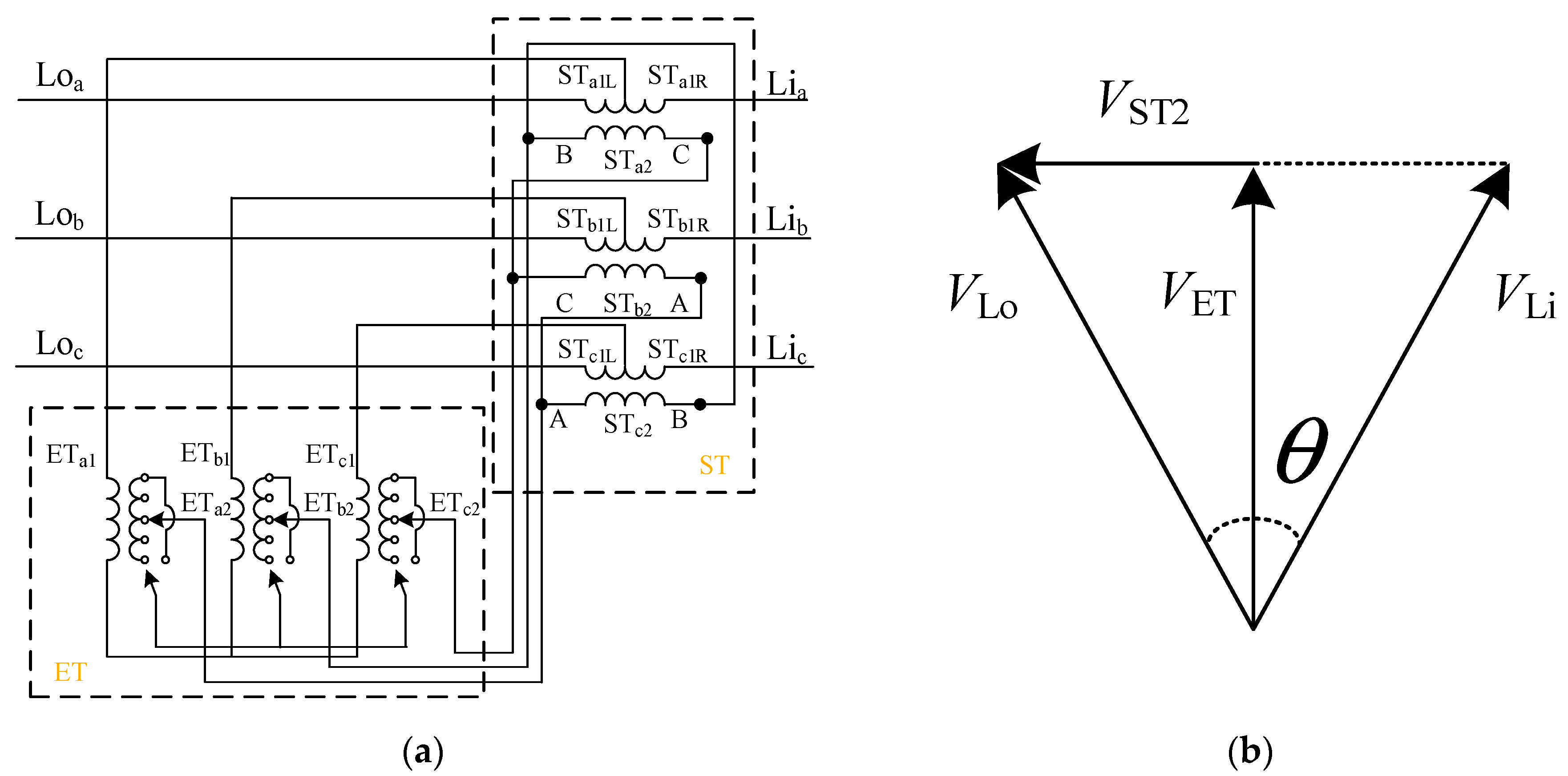
2.2.2. Working Process of a PST

PSTs are now widely used in high-voltage transmission networks in various countries, mainly for tidal adjustment [30]. The United States was the first country in the world to apply phase-shifting transformers in practical engineering. In the 1930s, a 66 kV/30 MVA mechanical phase-shifting transformer was installed in the United States [31], mainly for controlling the 66/132 kV electromagnetic ring network current problem in the region. Subsequently, research institutes and electrical equipment manufacturers in many countries, such as France, the Netherlands, Germany, Italy, and Belgium, conducted a lot of research into it, and transformer manufacturing companies, including, for example, Siemens and ABB, developed phase-shifting transformer products one after another and put them into engineering applications extensively [32,33,34]. At present, the research direction of phase-shift transformers in China is mainly focused on its modeling and simulation research, there is no practical engineering application yet but there are pilot engineering programs to explore [35]. In 2020, the Jiangsu power grid developed plans to install 220 kV phase shifting transformers in Yancheng, Wuxi, and Huai’an power grids [36]. In the same year, State Grid Jiangsu Electric Power Research Institute developed a science and technology project “Key technology research on controllable large-scale phase-shifting transformers for power grids”, while the phase-shifting transformers in China are manufactured by Tianwei Powertech Co. [37,38,39].
There are many types of PSTs, and the most widely used one is the double-core symmetrical controllable PST, whose structure and phase relationship is shown in Figure 2a. The PST consists of an excitation transformer (ET) and a series transformer (ST). The primary winding of the ST is connected to the line, and the middle tap of the primary winding is connected to the high voltage side of the ET to act as an excitation. The ST secondary winding is connected to the ET secondary winding in the wiring method shown in Figure 2a. With this wiring method, the secondary winding induced voltage of the ST is 90° different from the corresponding high-voltage winding induced voltage of ET, and the voltage VST2 is generated jointly with the primary winding of the ST so that a phase angle change is generated between the supply-side voltages of the PST as shown in Figure 2b.
VLi and VLo are the PST input and output voltages respectively, and VET indicates the excitation voltage provided by the center tap out of the ST primary winding to the ET primary winding. The specific regulation variables are derived and analyzed as follows:
V ST 2 = V Lo V ET = V Lo sin θ 2
V ST 2 = 3 V ET n k p = 3 V Lo cos θ 2 n k p
So
n k p = sin θ 2 3 cos θ 2 = tan θ 2 3
where n denotes the one-way adjustment gear and kp denotes the reference value of the phase change ratio. According to the adjustment requirements, the reference value of the phase ratio of the corresponding block is set, and combined with the application scenario shown in Figure 1, the closing loop device adjusts the phase difference of both sides of the bus during the closing loop through the PST control, so that the phase of both sides of the switch K2 or K4 is the same, realizing a very small impact or even a shock-free loop closing. After putting in the loop closing device, switch K1 will be disconnected again, thus realizing the non-stop loop closing transfer, and then the loop closing control device can be put into operation for a long time, or K3 can be closed and withdrawn from the device after control regulation.
Although the PST technology is relatively mature and experienced in operation and maintenance, the PST-based loop closing device has significant economic advantages compared with other converter-based solutions. However, considering the structural and operational characteristics of the distribution network in China, the loop closing transfer device is only a short time application of the loop closing scenario and generally needs to be withdrawn from operation after the loop closing is completed, resulting in a waste of resources. In order to further explore its application potential, considering that the shunt excitation transformer (ET) of the PST has neutral point by Y connection, the engineering utility value of the PST will be further enhanced and greatly expanded if the fault handling function of a small current system can be easily realized by modification.

2.3. Structure and Fault Characteristics of PSGT

Based on the analysis of the power grid structure of the distribution system and the structure and working scenarios of the phase-shifting transformer as a loop closing device, a phase-shifting transformer is proposed as a grounding transformer in consideration of the requirements for the transformation of the neutral grounding mode of the system in the development of urban distribution networks.

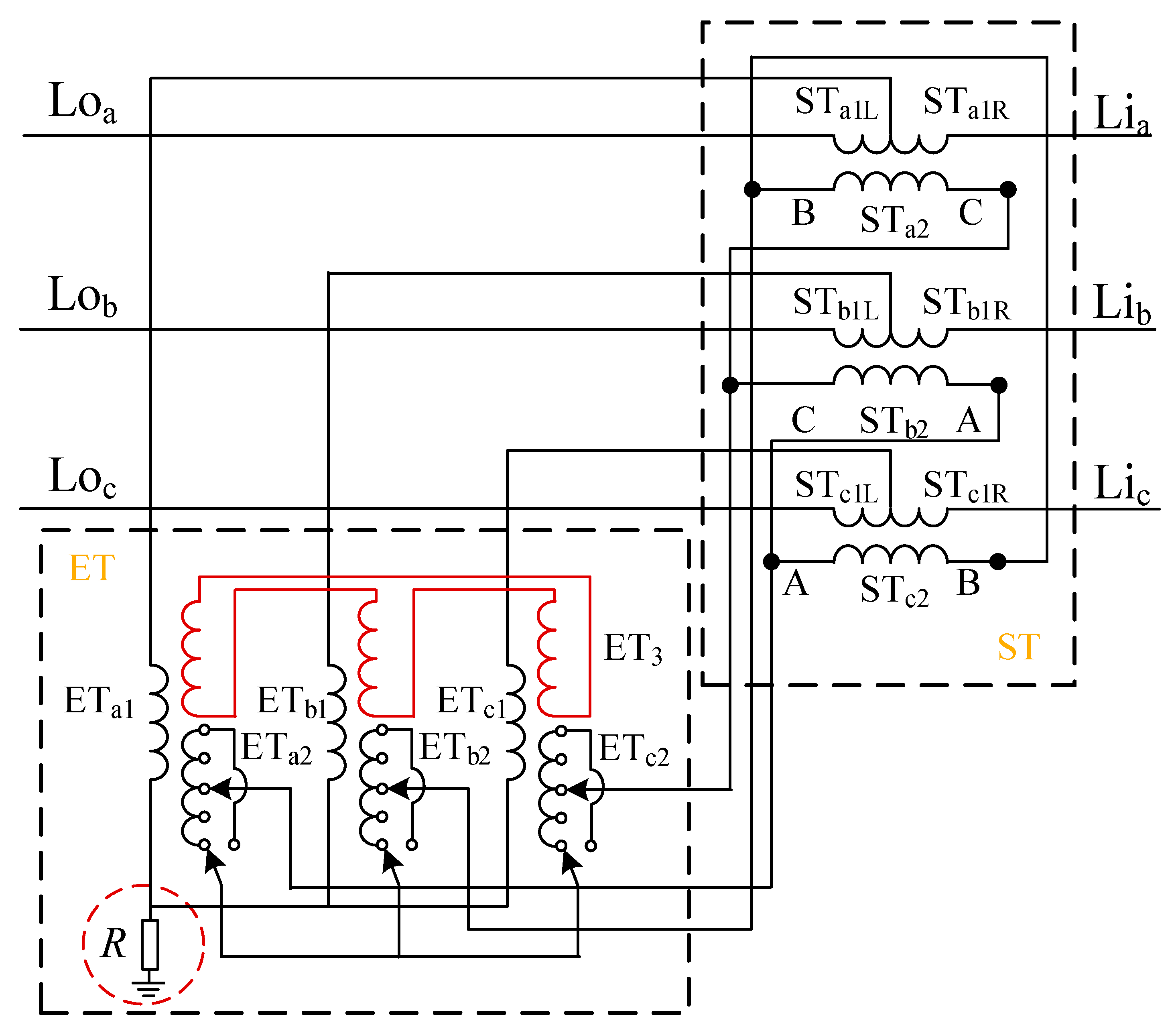
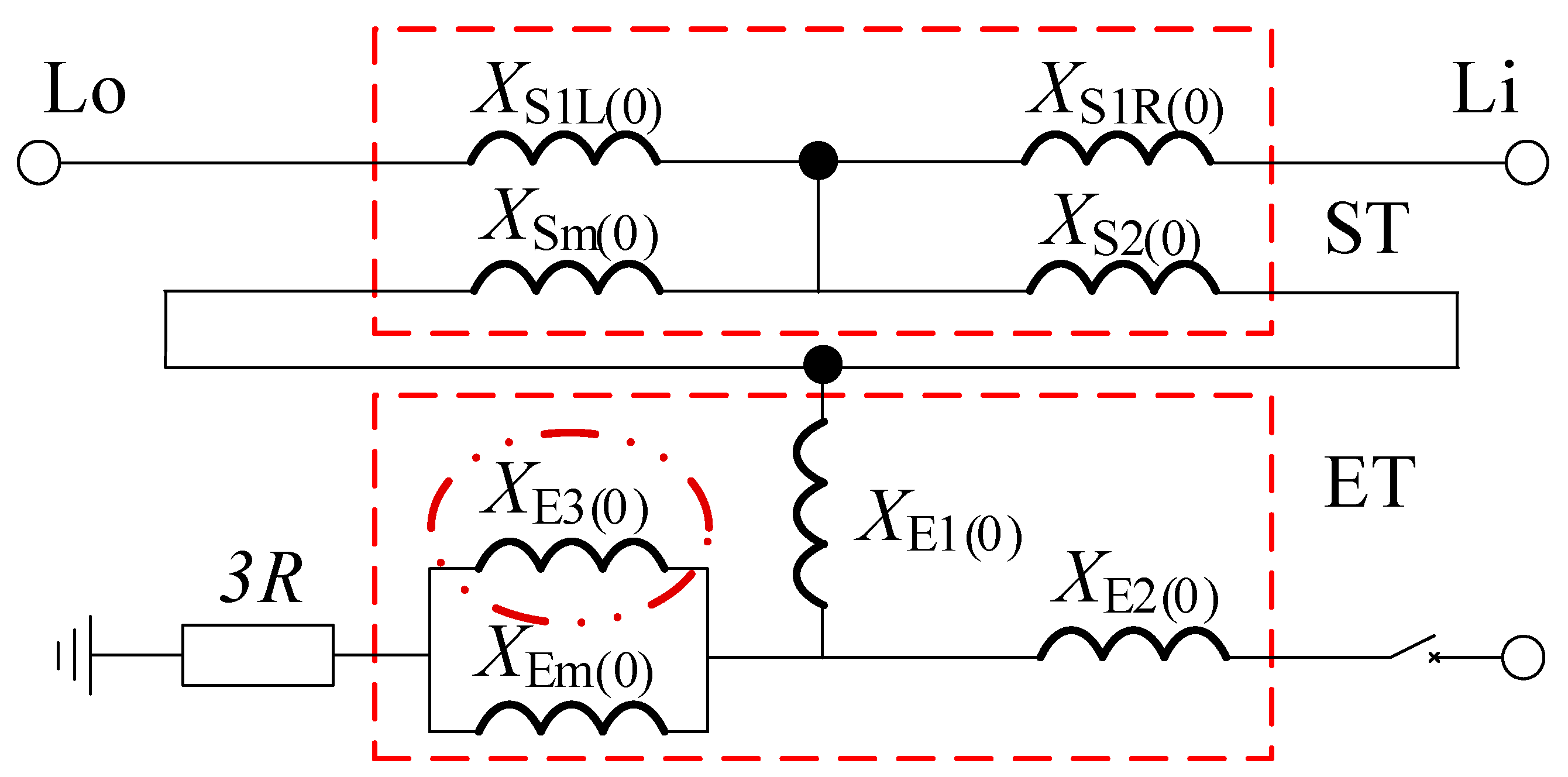
2.3.1. Structure of PSGT

Distribution system substations are generally wired according to Yd, a 10 kV voltage level distribution network is generally angle type wiring and there is usually no neutral point. A cable distribution network, in order to use the neutral point through a small resistance grounding method in the angled side to introduce the neutral point, usually uses grounding transformers to introduce an artificial neutral point. A grounding transformer has the advantages of high excitation impedance and a small no-load loss during the normal operation of the system, and small zero-sequence impedance and large positive and negative sequence impedance when a single-phase fault occurs. Since the ET winding of the excitation transformer of the PST is wired according to Yy and its ET primary is connected in series with the 10 kV bus through its ST primary, a slight improvement from the structure of Figure 2 can form a neutral point and construct a PSGT, whose structure is shown in Figure 3.
The structure of a PSGT relative to the PST series transformer has not changed, but its parallel transformer ET relative to the PST increased the neutral point via a small resistance grounding. For the distribution system, a fault occurs whether there is a valid zero-sequence circuit, and the symmetric component method is needed to further analyze the three-sequence circuit. The phase-shift cum grounding transformer three-sequence equivalent circuit is shown in Figure 4.
Where U P θ in Figure 4a is the PSGT regulated output voltage, XS1L is the leakage reactance of the primary left half winding of the PSGT series transformer ST, XS1R is the leakage reactance of the primary right half winding of ST, XS2 is the leakage reactance of the secondary winding of ST, XSm is the ST excitation reactance, XE1 and XE2 are the leakage reactance of the primary and secondary windings of the PSGT excitation transformer ET, respectively, XEm is the ET zero-sequence excitation reactance, and 3R is the triple grounding resistance. From Figure 4a,b, it can be seen that since the excitation variable of the PSGT mainly provides excitation for the secondary side of the series variable, at present, the positive sequence and negative sequence simplified equivalent reactance of the PSGT are as follows:
{ X P ( 1 ) = X S 1 L ( 1 ) + X S 1 R ( 1 ) X P ( 2 ) = X S 1 L ( 2 ) + X S 1 R ( 2 )
where XP(1) is the PSGT positive sequence equivalent reactance and XP(2) is the negative sequence equivalent reactance. The zero-sequence simplified equivalent reactance is obtained from Figure 4c.
X P ( 0 ) = ( X Sm ( 0 ) / / X S 2 ( 0 ) ) + X E 1 ( 0 ) + X S 1 x ( 0 ) + X Em ( 0 ) + 3 R
where XP(0) is the PSGT zero-sequence equivalent reactance when the ground fault occurs on the Lo side, XS1x(0) = XS1L(0), and XS1x(0) = XS1R(0) when the ground fault occurs on the Li side. The ST zero sequence excitation reactance XSm(0) and ET zero sequence excitation reactance XEm(0) have large values in non-three-phase three-column transformers and are approximated as open excitation branch circuits.
So XP(0) is infinite, the zero-sequence equivalent circuit has no pathway to provide a suitable short circuit current for short circuit cable lines, and single-phase faults may continue to develop into more serious accidents, so the structure is unable to effectively handle faults in systems accessed by the loop closing device. Therefore, the effect of XEm0 needs to be eliminated and the design further improved.
To compare and analyze the zero-sequence equivalent circuits of different types of transformer wiring, a third winding ET3 is added to the ET of the structure shown in Figure 3 and connected to the ET with a triangle connection, and the structure is shown in Figure 5.
The ET of the modified PSGT is wired as YN/D/Y, which is equivalent to introducing a transformer winding leakage reactance XE3(0) connected in parallel on both sides of XEm(0). The introduction of the third winding had no effect on the PSGT positive and negative sequence equivalent reactance, so both XP(1) and XP(2) remain unchanged, while the zero-sequence equivalent circuit is shown in Figure 6.
However, both XP(1) and XP(2) are constant, while the zero-sequence equivalent reactance is as follows:
X P ( 0 ) = X Sm ( 0 ) / / X S 2 ( 0 ) + X E 1 ( 0 ) + X S 1 x ( 0 ) + X Em ( 0 ) / / X E 3 ( 0 ) + 3 R
Since the values of XSm0 and XEm0 in non-three-phase three-column transformers are large, approximating that the excitation branch is open, the zero-sequence equivalent reactance can be simplified as follows:
X P ( 0 ) = X S 2 ( 0 ) + X E 1 ( 0 ) + X E 3 ( 0 ) + X S 1 x ( 0 ) + 3 R
From Equation (7), it can be obtained that the improved structure of the PSGT, as shown in Figure 5, can effectively eliminate the effects of XSm0 and XEm0 and make the zero-sequence equivalent circuit have a large zero-sequence current flow. In this paper, the fault characteristics of the input diagram structure PSGT are analyzed for a single-phase fault scenario occurring in a cable in the distribution network. Since the PSGT is improved based on a PST, only simulation verification is needed for its phase-shifting and loop closing functions, while for fault characterization, it needs to be applied to the scenario for analysis and simulation verification.

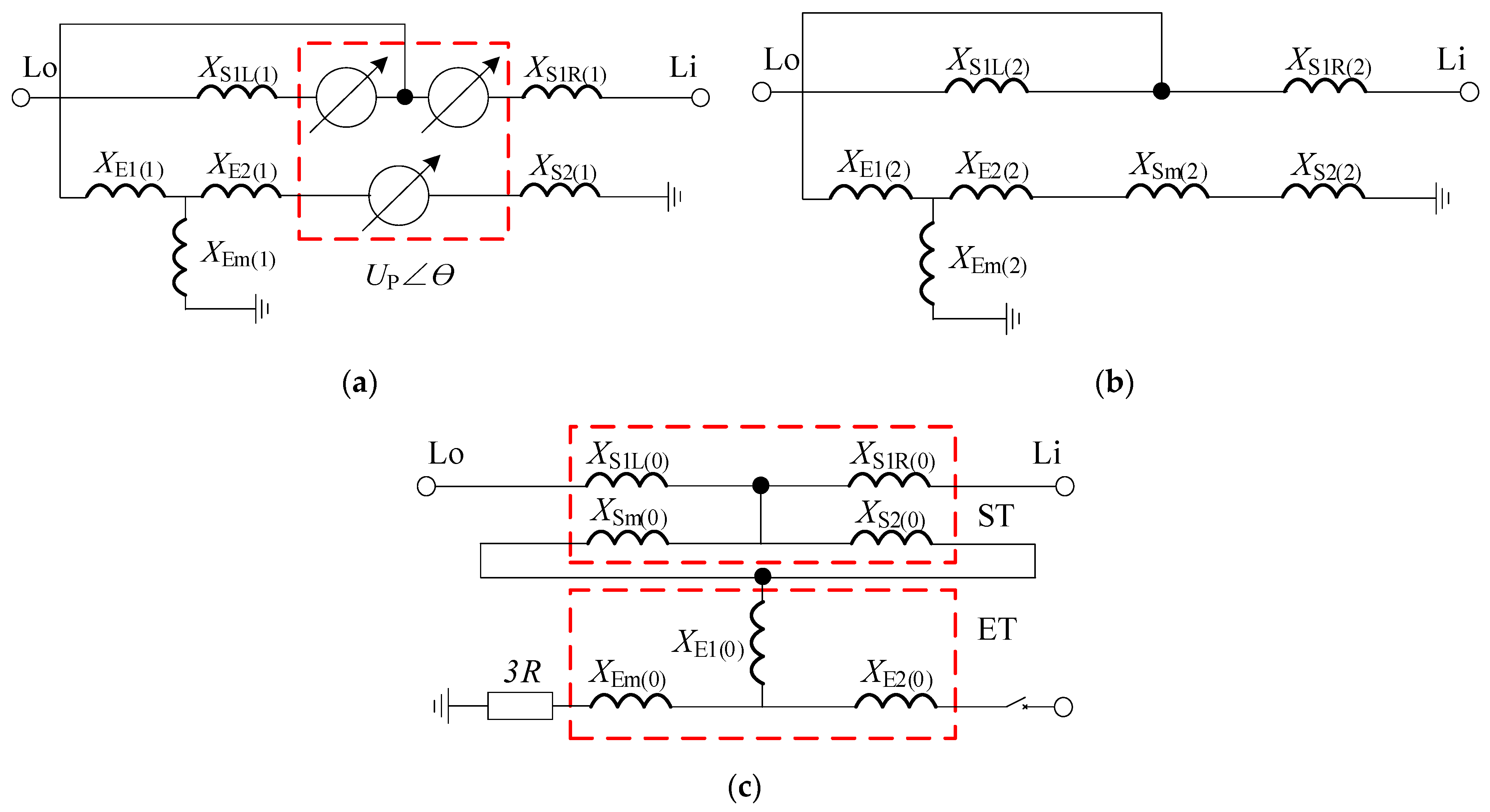
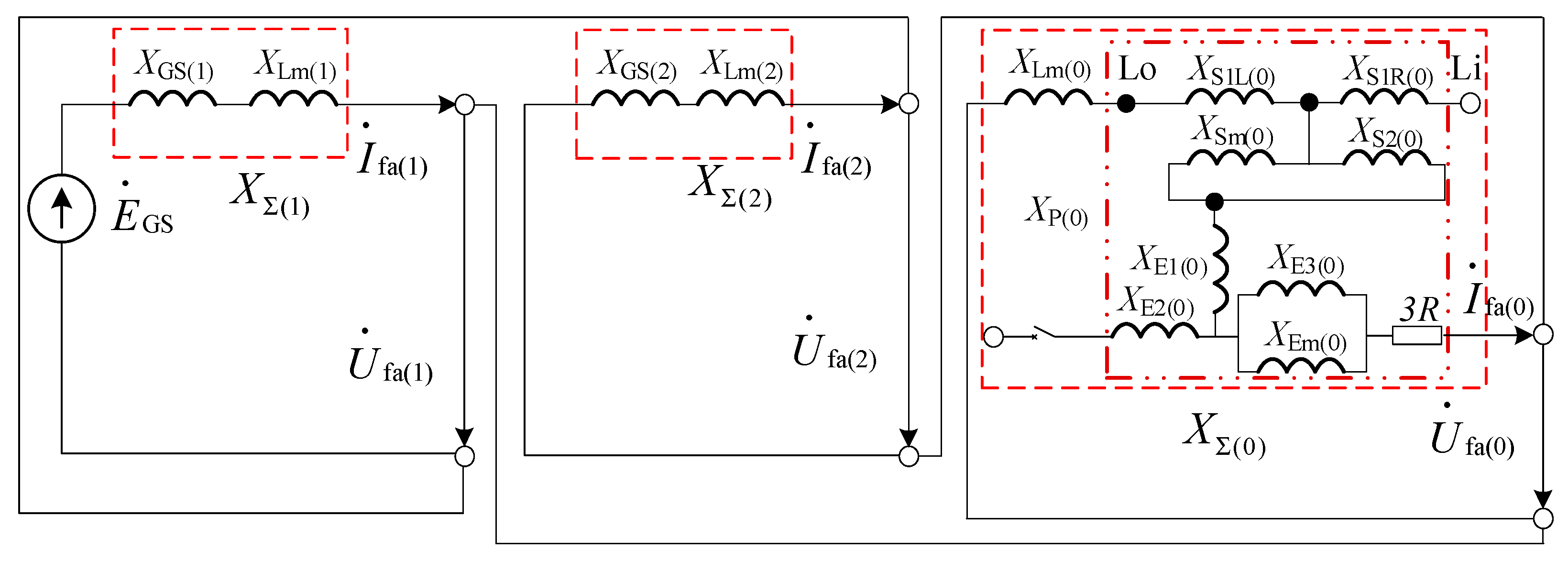
2.3.2. Fault Characteristics of a PSGT

Combining Figure 2 and Figure 5, and setting a single-phase fault in a cable of bus 1#, the simplified effect is shown schematically in Figure 7.
For the fault scenario shown, the symmetric component method is used to analyze the fault current situation. The boundary conditions are
{ I · a = I · fa I · c = I · b = 0 U · a = 0
Decompose phase A current into a positive sequence, negative sequence, and zero sequence components I · fa ( 1 ) , I · fa ( 2 ) , I · fa ( 0 ) , so
{ I · fa ( 1 ) = 1 3 ( I · a + e j 120 ° I · b + e j 240 ° I · c ) I · fa ( 2 ) = 1 3 ( I · a + e j 240 ° I · b + e j 120 ° I · c ) I · fa ( 0 ) = 1 3 ( I · a + I · b + I · c )
And
{ U · fa ( 1 ) + U · fa ( 2 ) + U · f a ( 0 ) = 0 I · fa ( 1 ) = I · fa ( 2 ) = I · fa ( 0 ) = 1 3 I · a
where U · fa ( 1 ) , U · fa ( 2 ) , U · fa ( 0 ) represents the positive and negative zero-sequence voltage, respectively.
The composite sequence network diagram of a single-phase ground fault occurring in a cable of the distribution network connected to the PSGT can be derived from Figure 5 and Figure 7 as shown in Figure 8.
Where XGS in the S-side substation equivalent reactance, XLm for the fault point and the busbar between the cable line reactance, from Figure 8 can be obtained from the distribution network a cable single-phase ground fault occurred in the three-sequence reactance as follows:
{ X Σ ( 1 ) = X GS ( 1 ) + X Lm ( 1 ) X Σ ( 2 ) = X GS ( 2 ) + X Lm ( 2 ) X Σ ( 0 ) = X Lm ( 0 ) + X P ( 0 )
I · fa ( 1 ) = I · fa ( 2 ) = I · fa ( 0 ) = E · GS X Σ ( 1 ) + X Σ ( 2 ) + X Σ ( 0 )
So the fault phase short circuit current can be obtained as follows:
I · a = 3 E · GS X GS ( 1 ) + X Lm ( 1 ) + X GS ( 2 ) + X Lm ( 2 ) + X P ( 0 ) + X Lm ( 0 )
The denominator of Equation (13) is a finite value, then the calculated value of short circuit current can be obtained, but the size of the specific current limit needs to be determined based on the value of the neutral grounding resistance of the PSGT excitation transformer. So the improved PSGT for single-phase fault lines can form an effective zero-sequence circuit, the appropriate parameters of the circuit components are set to be conducive to meet the protection of the closing switch action requirements, that is, the occurrence of a single-phase fault is conducive to the completion of the line selection trip function, and timely removal of the fault line. However, when a ground fault occurs after switching to the supply, four of the PSGT windings have a short circuit current passing through them. Considering the stable operation of the equipment and being able to complete the expected phase shifting and line selection tripping functions, further comparative analysis is required for the different resistance values of the resistors connected to the neutral point corresponding to the magnitude of the resulting short circuit current. In order to better illustrate the effectiveness of the PSCT function extension proposed in this paper, simulation analysis is performed based on the PSCAD/EMTDC environment.

3. Results and Discussion

The PSCAD/EMTDC environment is used to build a distribution system simulation model of a PSGT as a loop closing device using inbuilt components. The initial state is 10∠30° kV for bus 1# and 10∠0° kV for bus 2#. The whole simulation time is set to 2.1 s, with switches K1, K4, and K5 closed and switches K2 and K3 open. The current flowing through K2 at this time is shown in Figure 9.
The inrush current caused by the 0.5 s loop closing action is only 10 A, which can be regarded as the PSGT achieving the function of shock-free loop closing and 2 s when a cable of load 1# is set to have a short circuit fault of phase A lasting 1 s. It is necessary to compare and analyze the change of phase current and zero sequence current of each winding of the fault line and loop closing device when a single-phase fault occurs using a PST and PSGT. The phase current and zero-sequence current when a single-phase fault occurs in the loop device based on the phase-shifting transformer are shown in Figure 10.
Where IL1 is the bus 1# current, IET1 and IET2 are the primary and secondary winding currents of the excitation transformer, respectively, and IST1L, IST1R, and IST2 are the primary left and right winding and secondary winding currents of the series transformer, respectively. The subscripts a, b, and c indicate the three-phase currents, and 0 indicates the corresponding zero-sequence current.
When using the PST-based loop closing device, load 1# ground fault occurs, bus 1# and the excitation transformer of the loop closing device has almost no change in the three-phase current, while the fault phase current of the series transformer of the loop closing device shown in Figure 10d has a change of 2 A, and the small degree of current change cannot effectively provide the setting current value required for protection. As can be seen from Figure 10b, the maximum zero sequence current of the faulty line, as well as the installed looped device at this time is only 6 A, as analyzed in this paper, using the PST-based loop closing device cannot effectively deal with the fault while using the PSGT-based loop closing device, when a single-phase fault occurs, phase current and zero-sequence current are as shown in Figure 11.
Where IET3 is the secondary angular winding current added to the excitation transformer. From the analysis of Figure 11a, it can be seen that when the access to the PSGT occurs at 2 s with a single-phase fault short circuit in phase A, the phase current of phase A changes abruptly to 1000 A, which is four times the phase current in normal operation or without access to the PSGT. Combined with the analysis of the zero-sequence current situation in Figure 11b, it can be seen that the zero-sequence currents of each winding of the PSGT-based loop closing device are also equal, and there are two orders of magnitude changes in the zero sequence currents at this time compared with Figure 10b, indicating that the PSGT can effectively identify faults and handle them accurately. From Figure 11c,d, it can be seen that the phase currents of each winding involved in the zero-sequence loop of the PSGT-based loop closing device are subject to sudden changes, but the three-phase currents of each winding are equal at this time.
However, the winding three-phase currents are equal because the PSGT only affects the zero sequence loop when the loop is not switched to supply. In order to further analyze the effect of ground resistance magnitude, further simulations are needed for comparative analysis. Figure 12 shows the main winding currents of the loop closing device based on the PSGT after switching to supply.
Based on the tidal regulation capability of the Flexible Multi-state Switch (FMS), Soft Open Point (SOP), and Solid-State Transfer Switch (SSTS), the use of FMS, SOP, and SSTS as contact switches can realize the load transfer of the distribution network, but FMS, SOP, and SSTS are based on power electronics, which have higher investment costs and more complex control strategies and operation and maintenance [40,41,42]. Y et al. [43], based on a large amount of measurement data in distribution networks, predicted and analyzed the direct loop closing grid currents through dispatch and the loop closing inrush currents to provide auxiliary support for loop closing operations. For complex loop closing scenario regulation needs, the loop closing technology based on the PSGT loop closing device compares with the flexible loop closing technology based on the power electronics device, however, the loop closing technology based on the PSGT has a lower cost, simple operation and maintenance, better economy, and can form an effective zero-sequence loop to help distribution system fault routing, which is more scalable.
Where ILa5, ILa10, and ILa20 indicate the phase currents at fault point A when the PSGT neutral is grounded through 5 Ω, 10 Ω, and 20 Ω resistors, respectively. IL05, IL010, and IL020 in Figure 12b represent the fault point zero sequence currents when the PSGT neutral is grounded through 5 Ω, 10 Ω, and 20 Ω resistors respectively.
As can be seen from Figure 12a,b, the PSGT-based loop closing device is still able to handle faults in the distribution system after the transfer, and as the grounding resistance value becomes larger, the fault line grounding phase current, as well as the zero-sequence current, will be reduced, and the large resistance value may not meet the line selection trip requirements. However, too small a resistance value of the grounding resistor will lead to too much current flowing through each winding of the loop closing device, and there may be a risk of winding overcurrent, as shown in Figure 12c,d, where the overall analysis of the current flowing through the series transformer winding will be greater than the excitation transformer winding current. Based on the scenario set in this paper, the peak phase current can reach 1000 A when the resistance value is taken as 5 Ω. When taking the value of the grounding resistance and designing the insulation of the winding of the loop closing device, it is necessary to select the appropriate grounding resistance according to the actual demand.
Zhang Y et al. [44] concluded that the resistance value of neutral point grounding via small resistance is mainly based on the voltage withstanding level of neutral point and protection sensitivity, but the key is to use the capacitive current generated by the resistance value of small resistance to meet the system requirements. The overvoltage multiplier of small resistance value 6 Ω and 10 Ω was analyzed by double closed-loop simulation so that a relatively small resistance value was selected. Liu H et al. [45] analyzed the capacitive current under a single-phase ground fault occurring in a small ground current system. According to the planning of a power supply company’s distribution network, the fault current conditions and withstand voltage and breakdown levels under the small resistance grounding method using neutral point via resistance values of 10 Ω, 20 Ω, and 0.001 Ω were simulated and analyzed by setting different neutral grounding resistances and different fault grounding resistance conditions, and then 10 Ω was selected by comparative analysis. He T et al. [21] analyzed the problems in the protection calibration of grounded transformers connected to a 10 kV distribution network and proposed the quick-break protection calibration value of 546.5 - 4474 A in conjunction with the Chinese distribution network protection calibration standard.
This study simulates and analyzes the distribution system through the neutral point of a PSGT via small resistors with resistance values of 5 Ω, 10 Ω, and 20 Ω. When comparing and analyzing the fault current, the short circuit currents are 982.3 A, 692.9 A, and 468.1 A as the resistance value of the grounding resistor increases. When comparing and analyzing the fault overvoltage, the overvoltage multiplier decreases relatively as the resistance value of the grounding resistor increases. Considering the fault current and overvoltage, when the small resistance is 20 Ω, the short circuit current generated by the fault is too small, which is less than 546.5 A, and the feeder protection will not operate. When the small resistance value is 5 Ω, the short circuit current generated by the fault is too large, which will produce a large impact on the windings of the PSGT-based loop closing-device and will damage some distribution devices including the PSGT. Therefore, it is better to choose a smaller distribution device with a resistance value of 10 Ω for grounding when accessing the PSGT.

4. Conclusions

In this paper, a PSGT device based on a phase-shifting transforming loop transfer and neutral grounding via small resistance grounding is proposed, taking into account the change of neutral grounding mode due to the development of an urban distribution network. The phase shift function and fault characteristics of the proposed device are analyzed, and the effectiveness of the PSGT and the fault characteristics of the PST-based loop closing device in the distribution network under the small current grounding system is verified by simulation in the PSCAD/EMTDC environment, and the following conclusions are obtained.
  • PSGT neutral point via small resistance grounding method effectively improves the line zero sequence current, can effectively identify and deal with faults in the distribution network and reduce the economic loss caused by the rejection of the protection equipment;
  • PSGT is improved based on a PST, the application scenario is connected to the 10 kV side of the distribution network in the combined ring point, so it still retains its non-stop combined ring non-stop transfer function, making the phase-shifting and grounding transformer function more abundant;
  • PSGT-based loop closing device has an effective zero-sequence path before and after the fault occurs in the load transfer, and the short circuit current flowing through each winding of the PST will be different if the grounding resistance is taken as a different value, which is inversely proportional to the grounding resistance and can provide a basis for the design of the parameters of the loop closing device in engineering.

Author Contributions

Conceptualization, Z.X.; data curation, J.T., R.Q. and C.Z.; methodology, Y.Y.; software, J.T. and R.Q.; validation, Y.J., H.M. and C.Z.; formal analysis, Z.X.; investigation, J.T.; resources, H.M.; writing-original draft preparation, J.T. and Y.Y.; writing-review and editing, J.T. and Y.Y.; visualization, J.T., Y.Y. and C.Z.; supervision, R.Q.; project administration, Y.J.; funding acquisition, Y.Y. All authors have read and agreed to the published version of the manuscript.

Funding

This work was supported by the National Natural Science Foundation of China (51607068), and it was supported in prat by the Fundamental Research Funds for the Central Universities (2021MS068).

Institutional Review Board Statement

Not applicable.

Informed Consent Statement

Not applicable.

Data Availability Statement

Not applicable.

Conflicts of Interest

The authors declare no conflict of interest.

References

  1. Xiao, Y.; Lu, W.; Li, Y.; Zhong, Y.; Qi, Y.; Peng, J. Research on The Index System of Urban Distribution Network Development form and Its Evaluation Method. Power Syst. Prot. Control. 2021, 49, 62–71. [Google Scholar] [CrossRef]
  2. Jia, W.; Lei, C.; Ge, L.; Gao, H. Review of Domestic and International Development of Urban Distribution Networks and Technology Outlook. Power Capacit. React. Power Compens. 2020, 41, 158–168, 175. [Google Scholar] [CrossRef]
  3. Wu, H.; Chen, J.; Liao, F.; Lai, Y. Research on Centralized Grounding Protection for Small Resistance Grounded Distribution Systems. Power Syst. Prot. Control. 2021, 49, 141–149. [Google Scholar]
  4. Wang, Y.; Xue, Y.; Xu, B.; Li, T. Reverse-time Zero-sequence Overcurrent Protection for Ground Fault in Small Resistance Grounding Systems. Autom. Electr. Power Syst. 2018, 42, 150–157. [Google Scholar]
  5. Zeng, D.; Wang, G.; Li, H.; Liu, Y.; Guo, J. Multi-return Fault Analysis and Adaptive Zero Sequence Current Protection for Small Resistance Grounded Distribution Networks. Electr. Power Autom. Equip. 2019, 39, 45–52. [Google Scholar] [CrossRef]
  6. Xue, Y.; Liu, S.; Wang, Y.; Xu, B. Grounding Protection for Small Resistance Grounding System Based on Zero Sequence Voltage Ratio Braking. Autom. Electr. Power Syst. 2016, 40, 112–117. [Google Scholar]
  7. Guo, L.; Xue, Y.; Xu, B.; Cai, Y.; Zhang, S. Analysis of The Impact of Neutral Point Grounding Method on Power Supply Reliability. Power Syst. Technol. 2015, 39, 2340–2345. [Google Scholar] [CrossRef]
  8. Li, H.; Chen, J.; Zeng, D.; Liang, Y.; Wang, G. Highly Sensitive Zero Sequence Current Protection for Small Resistance Grounding Systems. Electr. Power Autom. Equip. 2018, 38, 198–204. [Google Scholar] [CrossRef]
  9. Liao, Y.; Chen, Y. Zero-sequence Protection by Ratio Law for 10kV Small Resistance Grounding System. Proc. CSU-EPSA 2020, 32, 50–56. [Google Scholar] [CrossRef]
  10. Wang, B.; Ren, X. Research on Single-phase Ground Fault Ranging of Collector Lines in Neutral Point Via Small Resistance Grounding Wind Farms. Proc. CSEE 2021, 41, 2136–2144. [Google Scholar] [CrossRef]
  11. Zhang, L.; Hao, D.; Zou, L.; Zhao, T. Structural Analysis of AC-DC Superimposed Distribution Network for Distributed Generation Access. High Volt. Eng. 2017, 43, 157–163. [Google Scholar] [CrossRef]
  12. Gao, L. Study on Grounding Variation and Small Resistance Selection in Small Resistance Grounding System. Electr. Power Surv. Des. 2020, 8, 23–29. [Google Scholar] [CrossRef]
  13. He, Z.; Li, B.; Liao, K.; Hu, S.; Ma, Z.; Li, J.; Yang, J. Key Technologies for Protection and Control of New Forms of Urban Power Grids. Proc. CSEE 2020, 40, 6193–6207. [Google Scholar] [CrossRef]
  14. Peng, K.; Zhang, C.; Xu, B.; Chen, Y.; Chen, J.; Zhao, X. Key Issues in Fault Analysis of Distribution Networks Containing High-density Distributed Power Sources. Autom. Electr. Power Syst. 2017, 41, 184–192. [Google Scholar]
  15. Yang, Y.; Tang, J.; Niu, C.; Zhao, C. Research on Flexible Combined-Loop Control Device and Control Strategy Based on Phase Shifting Transformer. J. North China Electr. Power Univ. 2022, 49, 48–57. [Google Scholar]
  16. Chen, L.; Xian, D.; Zheng, C.; Gao, H.; Fan, H.; Zhang, B. Analysis of operating characteristics of grounded transformers under system single-phase ground fault. Power Syst. Prot. Control. 2021, 49, 56–64. [Google Scholar] [CrossRef]
  17. Wang, T.; Xue, Y.; Zhao, X.; Zhang, J.; Li, Y.; Li, T. Transient Characteristics of Earth Fault in Arc Suppression Coil Grounded System with Different Grounding Resistances. J. Power Syst. Autom. 2019, 31, 43–51. [Google Scholar] [CrossRef]
  18. Yoon, H.I.; Choi, S.; Lee, H.; Nam, Y.; Rho, D. A study on operation algorithm of protection device for single line short circuit of GVT in ungrounded system. Trans. Korean Inst. Electr. Eng. 2019, 68, 253–261. [Google Scholar] [CrossRef]
  19. Zeng, X.; Zhuo, C.; Yu, K.; Xiang, G.; Li, J.; Zou, H. A Novel Method of Faults Arc Extinguishing and Feeder Protection Based on Voltage Regulating Intervention with Grounding Transformer Winding Taps for Distribution Networks. Proc. CSEE 2020, 40, 1523–1534. [Google Scholar] [CrossRef]
  20. Liao, F.; Chen, J.R.; Lai, Y.H.; Wang, Y.Q.; Xu, C. Research and Application of Zero-sequence Differential Protection of Grounding Transformer Under the Mode of Small Resistance Grounding. Guangdong Electr. Power 2020, 33, 100–106. [Google Scholar]
  21. He, T.; Chen, Y.; Liu, X.; Wu, P.; Chen, J. Cooperative rectification of grounding transformer and corresponding feeder protection. Electr. Appl. 2018, 37, 62–64, 70. [Google Scholar]
  22. Yang, Y.; Niu, C.; Tang, J.; Zhao, C.; Xu, Z. Research on AC-DC Side Loop Control Strategy of Flexible Loop-closing Device Based on Dual VSC. Available online: http://kns.cnki.net/kcms/detail/13.1212.TM.20211124.2054.006.html (accessed on 26 February 2022).
  23. Wang, X.; Xu, X.; Gan, D.; Peng, X.; Chen, Z.; Zhou, Y. Design scheme of online loop closing calculation software for distribution network based on mobile Internet. Power Syst. Prot. Control. 2017, 45, 128–133. [Google Scholar]
  24. Ye, Q.; Tang, G.; Wang, L.; Wu, G.; Gu, S. Development and application of circulation analysis system for closed loop operation of distribution network. Autom. Electr. Power Syst. 2002, 26, 66–69. [Google Scholar]
  25. Zhang, Z.; Xu, B.; Chen, Q.; Zhao, Y.; Feng, C. Power flow optimization control method for seamless self-healing distribution ring network with dual power supply failures. Autom. Electr. Power Syst. 2012, 36, 101–106. [Google Scholar]
  26. Wang, W.; He, Y.; Wang, B.; Zhang, Z.; Cai, Z.; Bian, L. A multi-line concurrent combined-loop tide calculation method. Energy Eng. 2018, 1, 20–24. [Google Scholar] [CrossRef]
  27. Zhao, C. The influence of power distribution network loop closure and power adjustment on relay protection. Electron. Technol. Softw. Eng. 2021, 1, 212–213. [Google Scholar]
  28. Chen, G.; Li, H.; Han, J.; Liu, X.; Li, J.; Peng, W. Risk assessment and simulation analysis of low-voltage distribution network switching from loop to power supply. Appl. Autom. 2020, 9, 76–79, 83. [Google Scholar] [CrossRef]
  29. Gao, F.; Liu, X.; Wang, L.; Li, B.; Zhao, X.; Liang, G.; Yu, X. Research on The Calculation Method of Maximum Step Voltage of Symmetrical Double Core Phase Shifting Transformer On-load Tap-changer. Proc. CSEE 2017, 37, 2110–2120. [Google Scholar] [CrossRef]
  30. Yang, Q.; Ban, G.; Xie, B.; Zeng, H.; Wen, Y.; Ma, X.; Huang, H. Deicing Method and Simulation of Phase-shifting Transformer for On-load Transmission Lines. Power Syst. Technol. 2021, 45, 3349–3355. [Google Scholar] [CrossRef]
  31. Lyman, W.J.; North, J.R. Application of large phase-shifting transformer on an interconnected system loop. Electr. Eng. 1938, 57, 579–588. [Google Scholar] [CrossRef]
  32. Bladow, J.K.; Montoya, A.H. Experiences with parallel EHV phase shifting transformers. IEEE Trans. Power Deliv. 1991, 6, 1096–1100. [Google Scholar] [CrossRef] [Green Version]
  33. Hui, H.; Yu, C.N.; Surendran, R.; Gao, F.; Moorty, S. Wind generation scheduling and coordination in ERCOT Nodal market. In Proceedings of the 2012 IEEE Power and Energy Society General Meeting, San Diego, CA, USA, 22–26 July 2012; pp. 1–8. [Google Scholar]
  34. Belivanis, M.; Bell, K.R.W. Use of phase-shifting transformers on the Transmission Network in Great Britain. In Proceedings of the 45th International Universities Power Engineering Conference UPEC2010, Cardiff, UK, 31 August–3 September 2010; pp. 1–5. [Google Scholar]
  35. Yu, H.; Zhou, F.; Yang, Z. Controlled phase shifter main circuit parameters design and steady-state characteristics analysis. China Electr. Power 2013, 46, 36–41. [Google Scholar]
  36. Cui, Y.; Yu, Y.; Yang, Z.; Yang, Y.; Wang, K. Evaluation of the effect of controlled phase shifter demonstration project scheme for ultra-high voltage grid. East China Power 2013, 41, 2237–2240. [Google Scholar]
  37. Chen, G.; Ding, L.; Tang, F.; Teng, Y.; Wei, W. Research on improving transmission capacity of Sichuan-Chongqing cross section using phase shifting transformer. Sichuan Electr. Power Technol. 2014, 37, 49–54. [Google Scholar]
  38. Wei, P.; Zhou, Q.; Zhu, X.; Ji, T.; Zhang, N. Study on the impact of controllable phase shifter on ultra-high voltage AC-DC access to the receiving grid. China Electr. Power 2018, 51, 7–12. [Google Scholar]
  39. Li, D.; Ding, J.; Wang, Z.; Dai, C.; Song, Y.; Shen, X. Research status and engineering applications of phase shift transformers. Smart Grid 2015, 3, 608–616. [Google Scholar] [CrossRef]
  40. Wang, C.; Wu, Y.; Sun, J.; Cha, X.; Ding, K.; Li, W. Bi-layer load balancing method in active distribution network based on flexible multi-state switch. Autom. Electr. Power Syst. 2021, 45, 77–85. [Google Scholar]
  41. Xiong, Z.; Chen, T.; Du LDai, Z.; Chen, J.; Xu, L. Optimal allocation of soft open point in active distribution network based on improved sensitivity analysis. Autom. Electr. Power Syst. 2021, 45, 129–137. [Google Scholar]
  42. Cui, X.; Zhang, Z.; Wang, Z.; Li, H.; Yang, Y. Novel rapid power switching strategy and its parameter calculation of induction motor-load based on solid state transfer switch. Trans. China Electrotech. Soc. 2016, 31, 21–28. [Google Scholar] [CrossRef]
  43. An, Y.; Chen, C.; Fan, R.; Li, S.; Zhu, Z.; Chen, L. Data-driven method for determining loop closure conditions in distribution networks. Water Resour. Power 2019, 37, 152–156. [Google Scholar]
  44. Zhang, Y.; Gu, C.; He, Z. A kind of resistance selection of neutral point via small resistance grounding in 10 kV distribution network with double ring network connection. Power Energy 2021, 42, 479–481, 491. [Google Scholar]
  45. Liu, H.; Zhu, D.; Liu, J.; Feng, W.; Tan, J.; Cheng, C.; Zhang, H.; Zhuan, S. Selection of small resistance in distribution network neutral point via small resistance grounding method. Power Syst. Clean Energy 2018, 34, 31–37. [Google Scholar]
Figure 1. Application scenarios of a phase-shifting transformer (PST).
Energies 15 02307 g001
Figure 2. (a) Structure of double-core symmetrical PST; (b) Regulation vector diagram of a PST.
Energies 15 02307 g002
Figure 3. Structure of a phase-shifting and grounding transformer (PSGT).
Energies 15 02307 g003
Figure 4. This is the phase-shifting and grounding transformer three-sequence equivalent circuit. (a) Positive sequence equivalent circuit; (b) Negative sequence equivalent circuit; (c) Zero sequence equivalent circuit.
Energies 15 02307 g004
Figure 5. Improved structure of a PSGT.
Energies 15 02307 g005
Figure 6. Zero-sequence equivalent circuit after adding windings.
Energies 15 02307 g006
Figure 7. A single-phase ground fault scene occurred in a cable of the distribution network.
Energies 15 02307 g007
Figure 8. Composite sequential network diagram.
Energies 15 02307 g008
Figure 9. Loop closing current flowing through K2.
Energies 15 02307 g009
Figure 10. This is based on the PST loop closing device and a fault current. (a) Bus 1# three-phase current; (b) Faulted line and closing loop device zero-sequence current; (c) Excitation transformer (ET) each winding three-phase current; (d) Series transformer (ST) each winding three-phase current.
Energies 15 02307 g010
Figure 11. This is based on the PSGT loop closing device and fault current. (a) Bus 1# three-phase current; (b) Faulted line and closing loop device zero-sequence current; (c) ET each winding three-phase current; (d) ST each winding three-phase current.
Energies 15 02307 g011
Figure 12. This is based on a different ground resistance PSGT and fault line current. (a) Bus 1# fault phase current; (b) Zero sequence current of the faulty line; (c) ET primary winding three-phase current; (d) ST primary winding three-phase current.
Energies 15 02307 g012
Publisher’s Note: MDPI stays neutral with regard to jurisdictional claims in published maps and institutional affiliations.

