Article

A Simulation Experimental Study on the Advance Support Mechanism of a Roadway Used with the Longwall Coal Mining Method

1
Shenmu Ningtiaota Coal Mining Company Ltd., Shaanxi Coal and Chemical Industry Group Company Ltd., Yulin 719300, China
2
Key Laboratory for Geomechanics and Deep Underground Engineering, China University of Mining & Technology-Beijing, Beijing 100083, China
3
Research Center of Geotechnical and Structural Engineering, Shandong University, Jinan 250061, China
*
Author to whom correspondence should be addressed.
All authors contributed equally to this work.
Energies 2022, 15(4), 1366; https://doi.org/10.3390/en15041366
Submission received: 26 December 2021 / Revised: 5 February 2022 / Accepted: 8 February 2022 / Published: 14 February 2022
(This article belongs to the Topic Support Theory and Technology of Geotechnical Engineering)

Abstract

:
Aiming to advance a support problem for roadways used with the longwall coal mining method, the S1202 working face of the Ningtiaota Coal Mine is taken as the engineering background. The monitoring and analysis of bolt force, anchor cable force and surrounding rock deformation of two types of roadways within the whole advance pressure influence range are carried out in the present paper. Based on this, a numerical calculation model consistent with the field is established, and numerical comparison tests under different influencing factors are carried out. The rationality of the numerical test results is verified by using the field monitoring data. At the same time, quantitative evaluation indexes, such as characterization deformation, are established, and the deformation law of roadways surrounding rocks under different advance passive support forces is analyzed. The advance support mechanism of the roadway used with the longwall coal mining method is clarified. The test shows that under the condition of no advance passive support, the maximum characteristic deformation of surrounding rock in the haulage roadway and ventilation roadway is 7.1 cm and 10.1 cm, respectively. The above surrounding rock deformation still meets the requirements of on-site safety production. The research results can provide experimental support for the advance support parameters of the roadway used with the longwall coal mining method.

1. Introduction

Coal is an important consumer energy in the world, accounting for 27% of the global primary energy consumption structure in 2019. Underground mining methods mainly include short wall mining method and longwall mining method. Longwall mining method is widely used around the world due to its high productivity and good ventilation performance. This mining method [1,2,3,4,5,6,7] needs to excavate two mining roadways in advance and reserve one roadway pillar to mine one working face. In the process of coal mining, the roadway surrounding rock in a certain range in front of the coal mining face is affected by the superposition of mining stress and in situ stress. The influence range of this superimposed stress is named the advance pressure influence range, which results in the roadway support system facing great challenges [8,9].
At present, the advance support forms of active anchor mesh support and passive hydraulic prop (support) are generally adopted within the scope of advance influence [10,11,12,13,14]. Wang et al. [12,13] optimized the support parameters of the anchor mesh and hydraulic prop within the advance pressure influence range in the Suncun Coal Mine. Tan et al. [14] studied the deformation and failure characteristics of the roadway affected by the advance pressure in Daichiba Coal Mine, and put forward the technical scheme of using a hydraulic prop with anchor mesh cable.
The above experts avoided the surrounding rock damage caused by the advance pressure of the working face by erecting dense props (support) [15,16]. However, this form restricted the safe, intelligent and efficient production of coal, and there were some problems, such as the high cost and construction efficiency. Therefore, it is urgent to clarify the advance support mechanism of the roadway of the longwall coal mining method, and coordinate the coupling support relationship between active support [17] and passive support, so as to gradually optimize the advance passive support until the advance passive support is cancelled.
On this basis, the S1202 working face of Ningtiaota Coal Mine is taken as the engineering background. The quantitative evaluation index is established to analyze the evolution law of stress and displacement of the roadway surrounding the rock under different advanced passive support parameters by using the combination method of the field test and numerical test. The mechanism of advance support in longwall mining roadways is clarified, which lays the foundation for the optimization of advance support parameters.

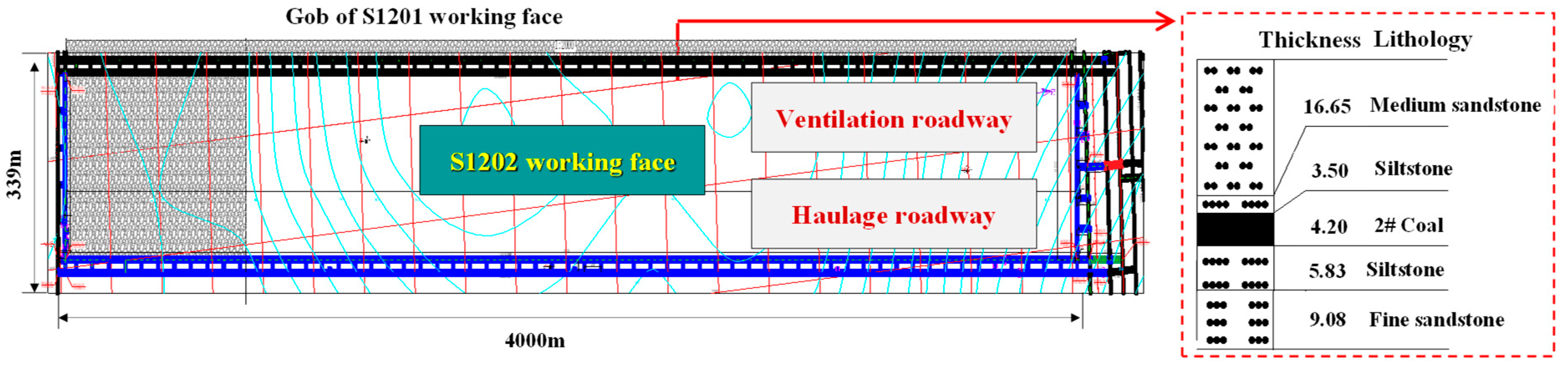
Engineering Background

Ningtiaota Coal Mine is located in Western China, with a design annual output of 20 Mt/a, which is a typical 10 million ton modern mine. The strike length of the S1202 working face of the mine is 4000 m, and the dip length is 339 m. The main mining is 2-2 coal, the average coal thickness is 4.2 m and the average buried depth is 162 m. The basic roof of the working face is mainly fine sandstone with an average thickness of 16.65 m; the immediate roof is mainly siltstone, with an average thickness of 3.50 m; the immediate floor is mainly siltstone, with an average thickness of 5.83 m; and the basic floor is mainly fine sandstone with an average thickness of 9.08 m. The rock stratum of the working face is shown in Figure 1.
The roadway is designed as a rectangular section, with a clear width of 5800 mm and a clear height of 3500 mm. In terms of the active support of the roadway, the bolt mesh support was adopted for the haulage roadway and ventilation roadway. The roof bolt was Φ 22 × 2500 mm, row spacing 1700 × 1000 mm, and the roof anchor cable was Φ 17.8 × 7000 mm, spacing 3000 mm. In terms of the advance passive support of the roadway, ZTC10696/27/50 advance hydraulic support was adopted for the haulage roadway and ventilation roadway, with the working resistance of 0.1 MPa. The specific support parameters are shown in Figure 2.
A comprehensive monitoring section is arranged 100 m in front of the haulage roadway and ventilation roadway to monitor the displacement of roadway surrounding rock and the force of the supporting components within the whole advance pressure influence range, as shown in Figure 2. The specific layout of the monitoring section was as follows: infrared anchor dynamometers were installed at the end of roadway roof cables and bolts to continuously monitor the force change of the supporting components. Displacement monitoring points were arranged at the roadway roof, roadway floor and the middle of the two sides to continuously monitor the roof and floor convergence deformation and convergence deformation of the two sides. The displacement change curve of the roadway surrounding rock within the whole advance pressure influence range is shown in Figure 3a, the force change curve of the anchor cable is shown in Figure 3b and the force change curve of bolt is shown in Figure 3c. The “-” of the abscissa in Figure 3 represents the front of the working face, that is, the advance working face.
According to the analysis in Figure 3:
(1) With the advance of the working face (−100 m~0 m), the roof and floor convergence and convergence deformation of the 2 sides show an increasing trend. In the whole advance process, the maximum value of the roof and floor convergence deformation is 7.4 cm, and the convergence deformation of the 2 sides is 7.1 cm in the haulage roadway, as shown in Figure 3a. The maximum value of the roof and floor convergence deformation is 8.9 cm, and the convergence deformation of the 2 sides is 7.6 cm in the ventilation roadway. The above data show that the deformation of the roadway surrounding rock can meet the requirements of safety production during the service period of the whole working face.
(2) With the advance of the working face (−100 m~0 m), the force of the bolt and anchor cable in the 2 roadways shows an overall growth trend, as shown in Figure 3b,c.
① In terms of the bolt force: within 17.3 m to 0 m in advance (−17.3 m~0 m), the bolt force begins to significantly increase, and the maximum force of the bolt is 21.1 kN in the haulage roadway. Within 26.6 m to 0 m in advance (−26.6 m~0 m), the bolt force begins to significantly increase, and the maximum force of the bolt is 17.0 kN in the ventilation roadway. The breaking force obtained from the laboratory test of this kind of bolt is 213 kN, so its strength utilization rate is 10.0% and 13.8%, respectively.
② In terms of the cable force: within 18.7 m to 0 m in advance (−18.7 m~0 m), the cable force begins to significantly increase, and the maximum force of the cable is 138.3 kN in the haulage roadway. Within 24.9 m to 0 m in advance (−24.9 m~0 m), the cable force begins to significantly increase, and the maximum force of the cable is 144.1 kN in the ventilation roadway. The breaking force obtained from the laboratory test of this kind of cable is 320 kN, so its strength utilization rate is 43.2% and 45.0%, respectively.
The above data show that under the current active and passive support conditions, the deformation of the roadway surrounding rock can meet the on-site safety production, and the bolt (cable) cannot give full play to its support efficiency.

2. Numerical Test of the Advance Support Mechanism

Based on the field test, in order to clarify the advance support mechanism of the longwall mining roadway in the coal mine and optimize the advance passive support parameters, the numerical test research on the advance support mechanism was carried out.

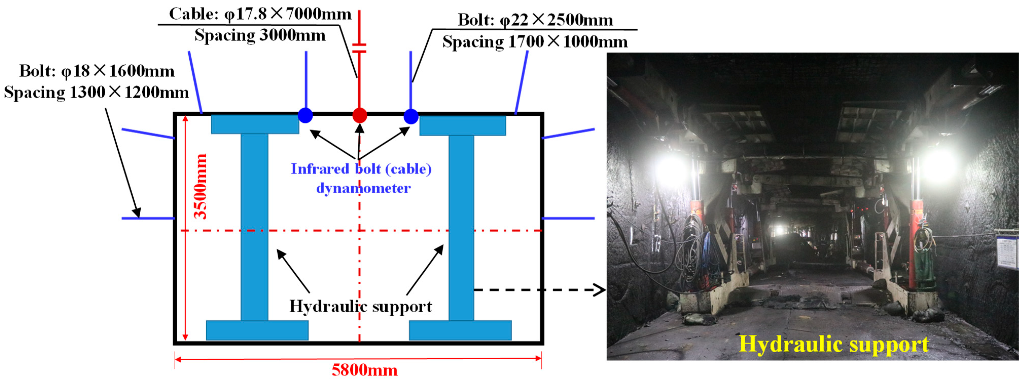
2.1. Schematic Design

In this section, the roadway section size, bolt (cable) support parameters and advance passive support distance are taken as the invariants. The selection of their simulation data in the numerical test were the same, and the values were consistent with the field. The values of the roadway section size and bolt (cable) support parameters are shown in Figure 2. The advance passive support distance was selected as 0~20 m. The research was carried out with the passive support force of the hydraulic support as the variable. There were 4 types of schemes in the test, including the original passive support force (scheme I), 2/3 passive support force (scheme II), 1/3 passive support force (scheme III) and no passive support force (scheme IV). The specific parameters are shown in Table 1.

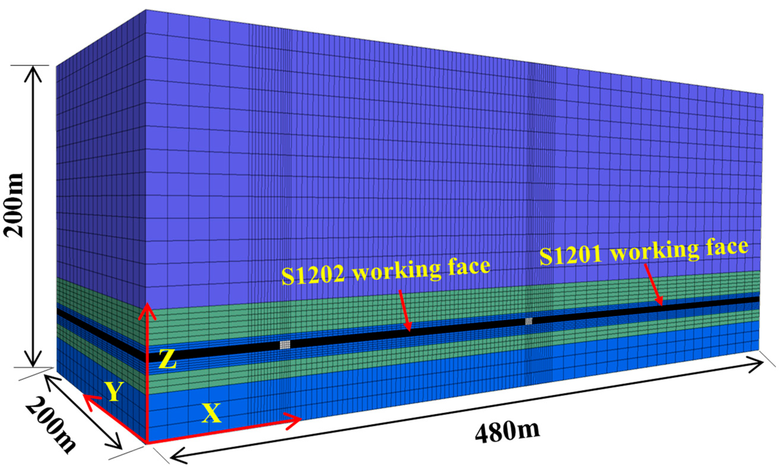
2.2. Establishment of Model and Evaluation Index

(1) Model establishment
A numerical calculation model consistent with the field conditions is established, and the calculation range is 480 m × 200 m × 200 m (length × wide × high) by FLAC 3D, as shown in Figure 4. The bottom of the model is fixed, the side restricts the horizontal movement, and the initial stress is applied to make the test face reach the in situ stress level. The Mohr Coulomb constitutive model is adopted for the surrounding rock, cable and bolt are simulated using the cable element, and the uniform load is adopted for simulating the advanced hydraulic support. The physical and mechanical parameters of each rock stratum are shown in Table 2.
The excavation simulation is presented according to the sequence of “coal mining in S1201 working face→retaining 15 m coal pillar→excavation of haulage roadway and ventilation roadway in S1202 working face→coal mining in S1202 working face”. The surrounding rock displacement monitoring is carried out for the haulage roadway and ventilation roadway of the S1202 working face in the whole process.
(2) Establishment of the quantitative evaluation index
In order to compare and analyze the displacement change law of the roadway surrounding rock under different schemes, the quantitative evaluation index, such as the surrounding rock characteristic deformation, Davg, is established to better optimize the advance passive support parameters.
D a v g = n = 1 n = i ( D i - r f + D i - s 2 n )
where D a v g is the characteristic deformation of the roadway surrounding rock of each scheme, cm. The larger the D a v g , the worse the control effect of the roadway surrounding rock. The smaller the D a v g , the better the control effect of the roadway surrounding rock; n is the number of displacement monitoring sections. D i - r f is the roof and floor convergence deformation of section i in the roadway, cm. D i - s is the convergence deformation of the two sides of section i in the roadway, cm.

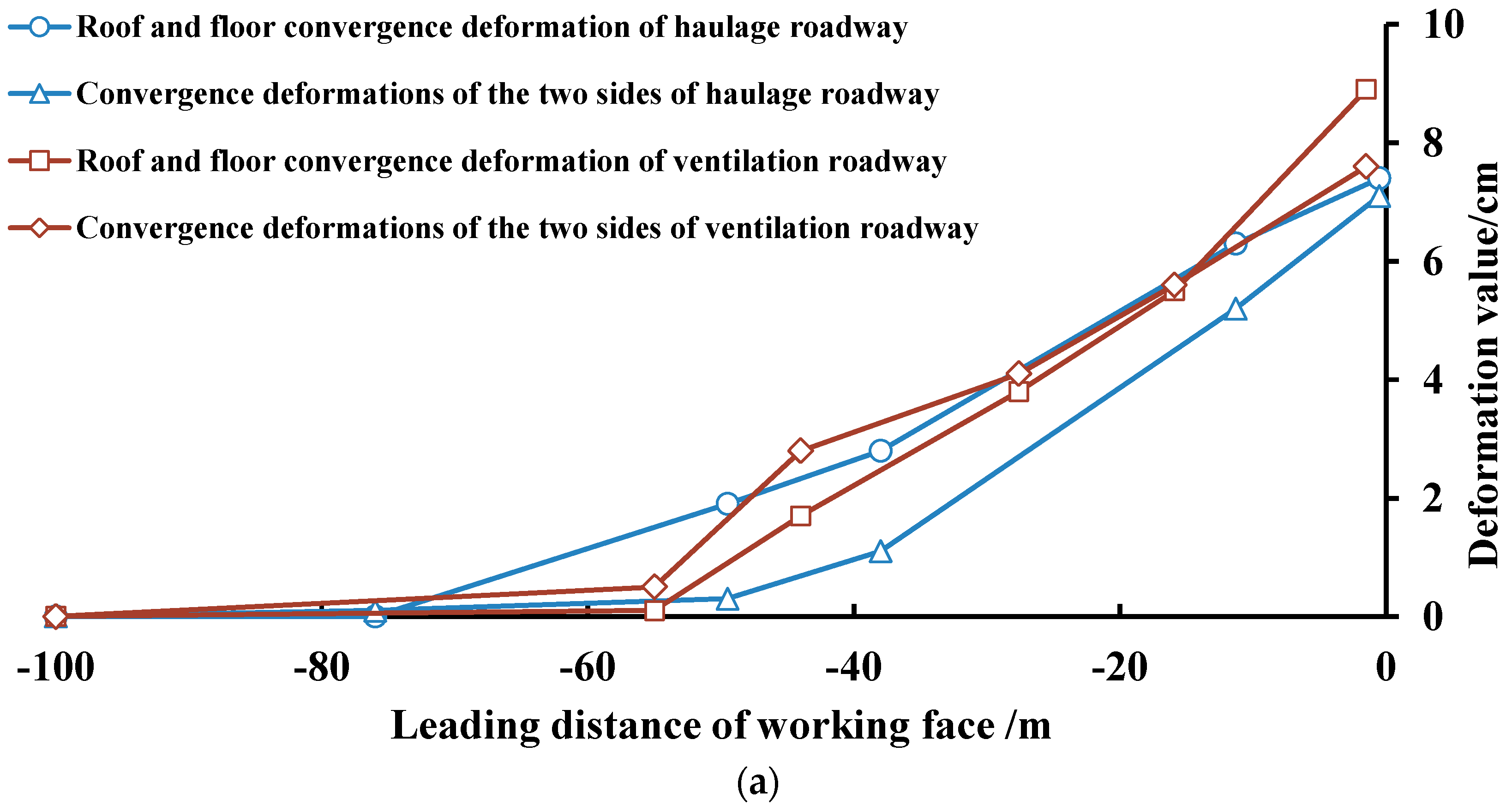
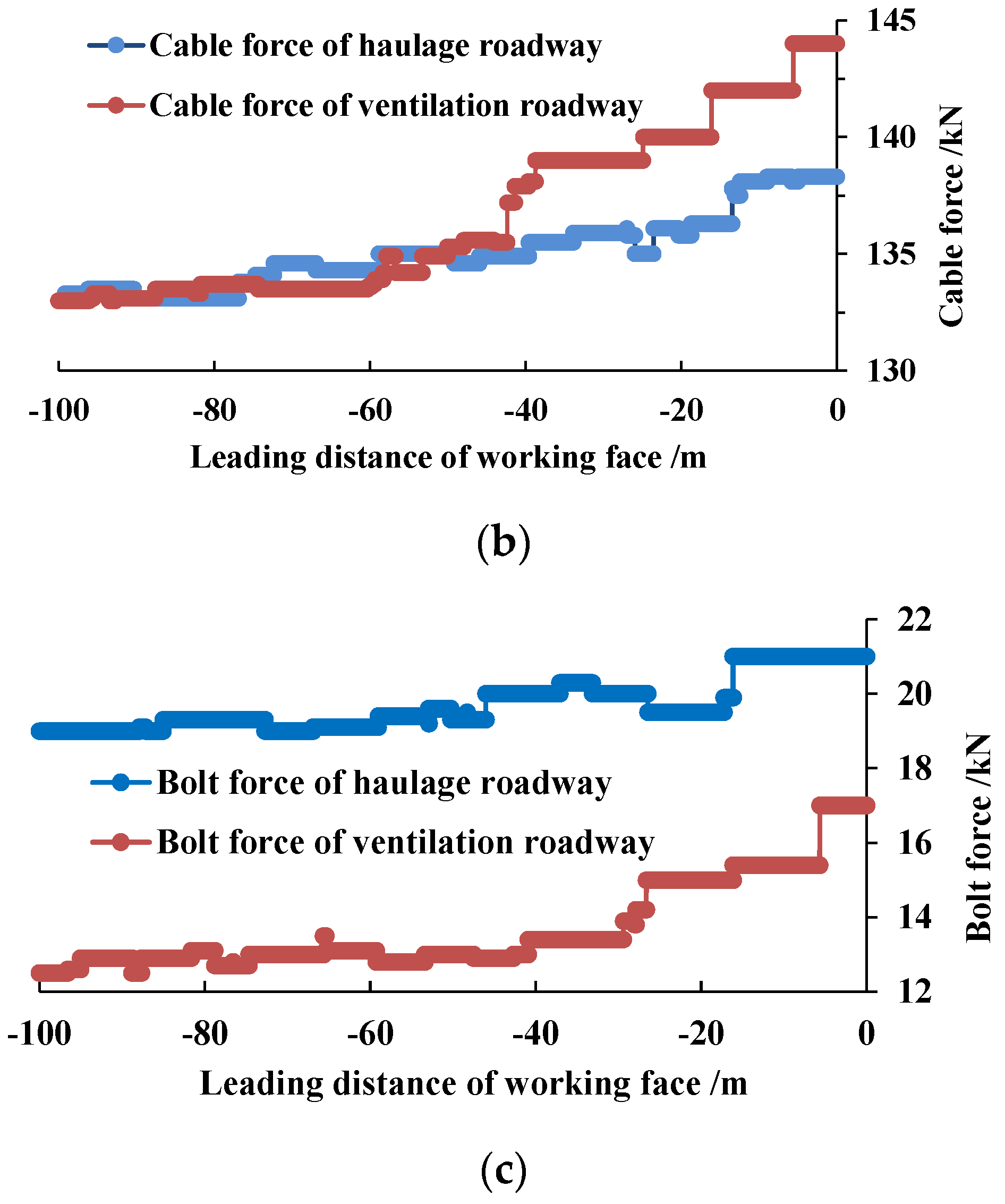
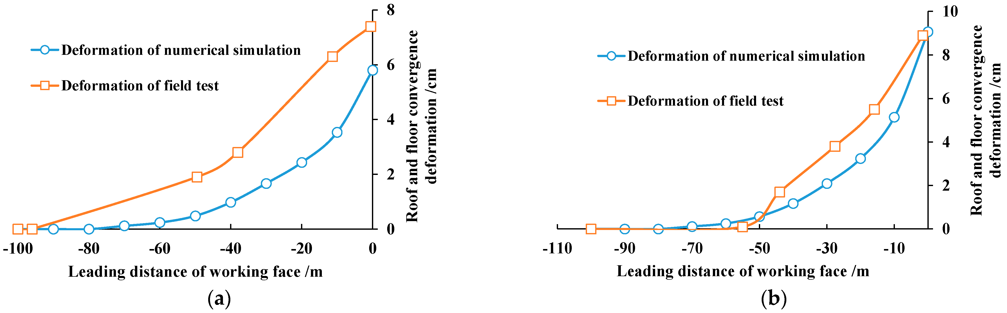
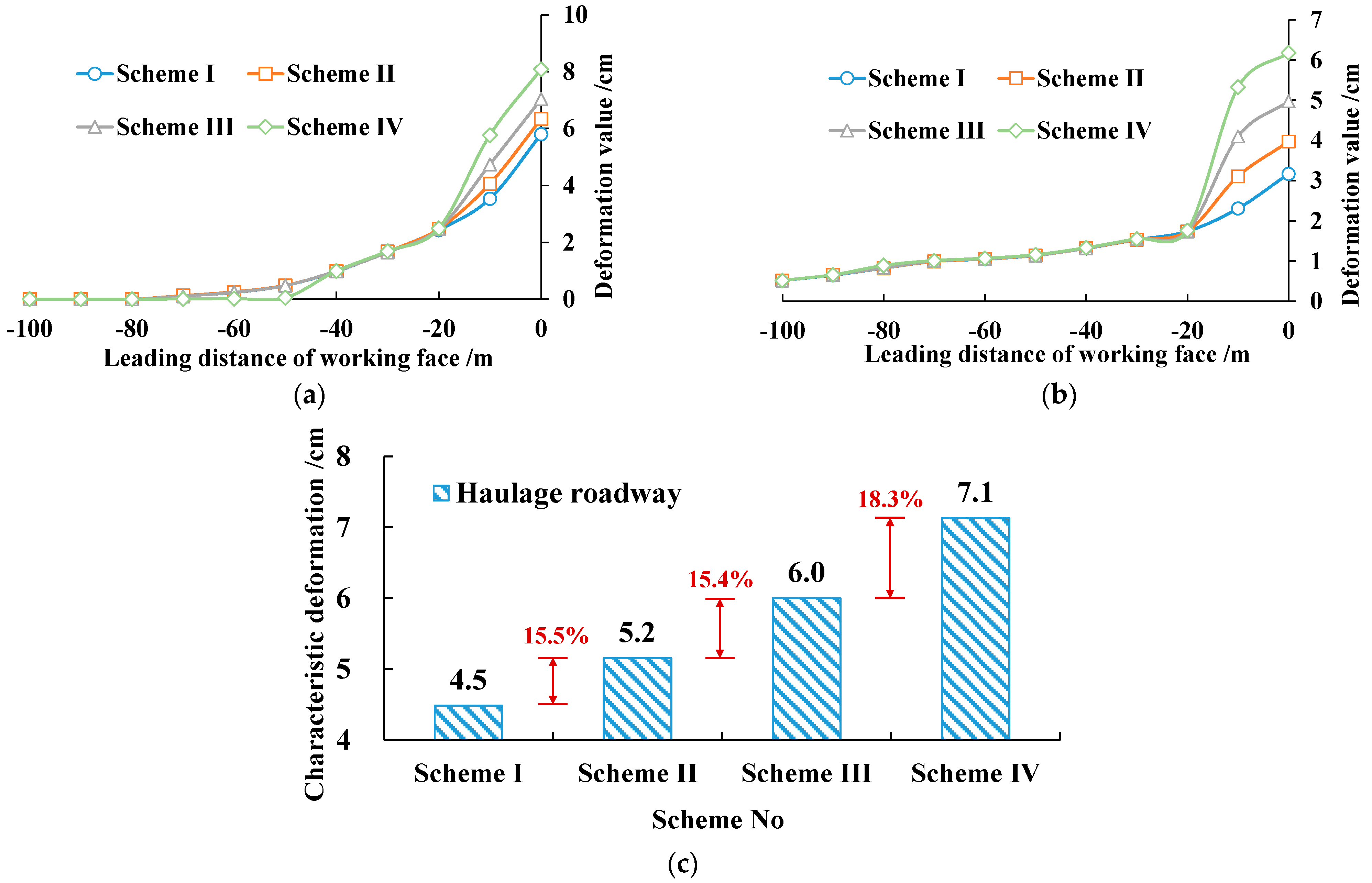
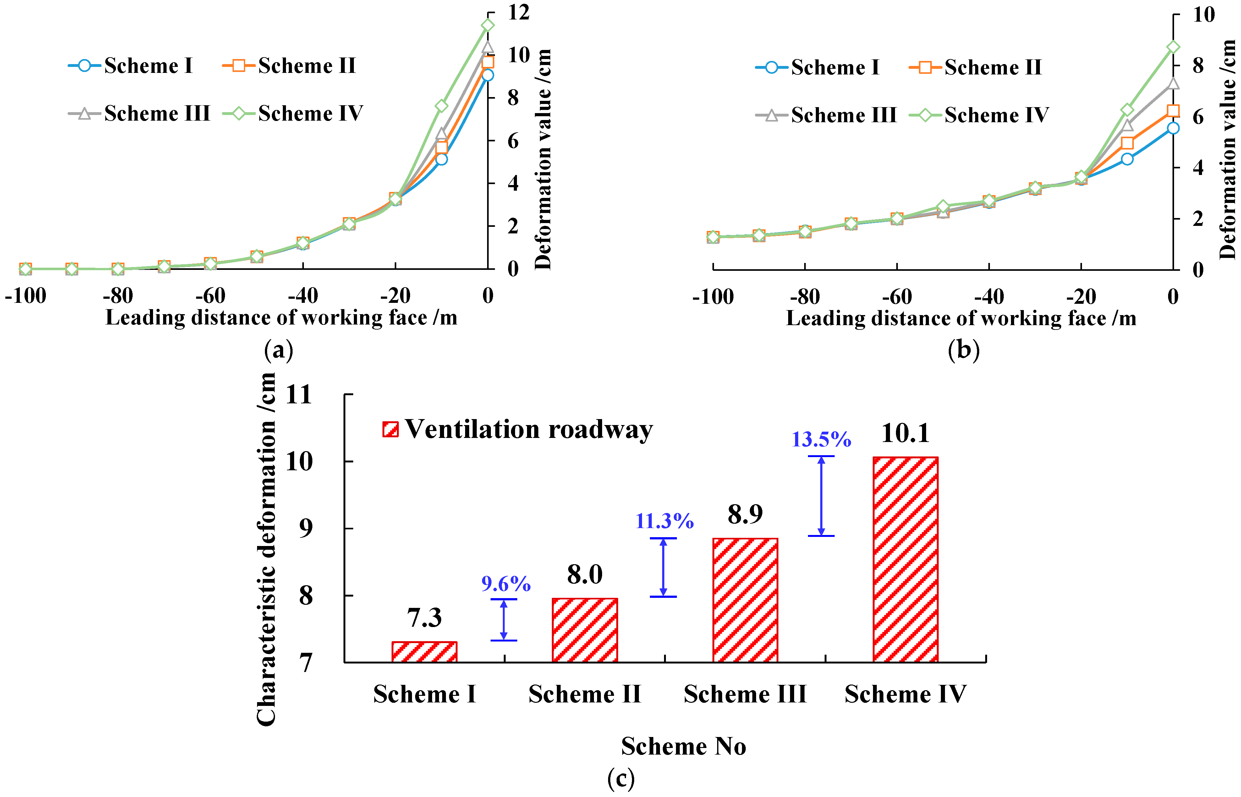
2.3. Result Analysis

(1) Comparison between the numerical test and field test
It can be seen from the analysis in Figure 5 that the variation law of the roof and floor convergence deformation of the haulage roadway and ventilation roadway in the numerical simulation is similar to that in the field test. The maximum values of the roof and floor convergence deformation in the ventilation roadway are 9.1 cm and 9.0 cm, respectively, in the numerical simulation and field test. The difference rate is 1.1%. The maximum values of the roof and floor convergence deformation in the haulage roadway are 5.8 cm and 7.4 cm, respectively, in the numerical simulation and field test. The difference rate is 22.9%. The above variation rules and data show that the numerical simulation established by using the field parameters in this section can reflect the field situation to a certain extent. Therefore, the further research on the optimization of the advance passive support parameters was carried out based on the numerical model.
(2) Numerical test on the optimization of the advance support
The numerical comparison tests of the haulage roadway and ventilation roadway were carried out according to the designed test scheme. The deformation law of the surrounding rock within the advance pressure influence range of the haulage roadway is shown in Figure 6, and the deformation law of the surrounding rock within the advance pressure influence range of the ventilation roadway is shown in Figure 7.
(1) Analysis of the monitoring results of the haulage roadway
According to the analysis in Figure 6:
① With the coal mining of the working face, the roof and floor convergence deformation and convergence deformation of the two sides of the haulage roadway show an increasing trend within the range of −100 m~0 m. This phenomenon is particularly obvious within the range of −20 m~0 m, as shown in Figure 6a,b. Therefore, it can be determined that the advance pressure influence range of the haulage roadway is −20~0 m.
② Within the scope of the advance pressure influence, the surrounding rock deformation of the haulage roadway gradually increases, with the support force of the advance support gradually decreasing (scheme I~scheme IV). The maximum value of the roof and floor convergence deformation of the haulage roadway increases from 5.8 cm to 8.1 cm, and the maximum value of the convergence deformation of the two sides increases from 3.2 cm to 6.2 cm, as shown in Figure 6a,b. The results show that with the decrease in the advance support force, the advance influence pressure on the roof of the haulage roadway is more obvious.
③ The characteristic deformation of the haulage roadway of each scheme is 4.5 cm, 5.2 cm, 6.0 cm and 7.1 cm, respectively. With the decrease in the support force of the advance support, the increased rates of the characteristic deformation are 15.5%, 15.4% and 18.3%, respectively, as shown in Figure 6c. It shows that the deformation of the surrounding rock of the haulage roadway increases the most when 1/3 support force decreases to 0 support force. However, the characterization deformation is only 7.1 cm, which meets the requirements of safe production, which provides support for the field support system without advance support.
(2) Analysis of the monitoring results of the ventilation roadway
According to the analysis in Figure 7:
① With the coal mining of the working face, the roof and floor convergence deformation and convergence deformation of the two sides of the ventilation roadway show an increasing trend within the range of −100 m~0 m. This phenomenon is particularly obvious within the range of −20 m~0 m, as shown in Figure 7a,b. Therefore, it can be determined that the advance pressure influence range of the ventilation roadway is −20~0 m.
② Within the scope of advance pressure influence, the surrounding rock deformation of the ventilation roadway gradually increases with the support force of the advance support gradually decreasing (scheme I~scheme IV). The maximum value of the roof and floor convergence deformation of the ventilation roadway increases from 9.1 cm to 11.4 cm, and the maximum value of the convergence deformation of the two sides increases from 5.6 cm to 8.7 cm, as shown in Figure 7a,b. The results show that with the decrease in the advance support force, the advance influence pressure on the roof of the ventilation roadway is more obvious.
③ The characteristic deformation of the ventilation roadway of each scheme is 7.3 cm, 8.0 cm, 8.9 cm and 10.1 cm, respectively. With the decrease in the support force of the advance support, the increased rates of the characteristic deformation are 9.6%, 11.3% and 13.5%, respectively, as shown in Figure 7c. It shows that the deformation growth range of the surrounding rock of the ventilation roadway increases gradually with the decrease in the support force of the hydraulic support. However, the maximum value of the characterization deformation is only 10.1 cm, which meets the requirements of safe production, which provides support for the field support system without advance support.

3. Research Discussion

(1) During the mining period of the working face, the characteristic deformation of the ventilation roadway was 1.4 times that of the haulage roadway. The reason could be that there was a 17 m coal pillar on the right side of the ventilation roadway, and the stress on the pillar was concentrated. Therefore, it is suggested that an asymmetric design should be carried out for two roadways when designing the roadway support parameters, and the support of the roadways adjacent to the coal pillars should be strengthened.
(2) Within the influence range of the advance pressure, the passive support by hydraulic support (prop) and active support by the bolt (cable) play the role of supporting the surrounding rock together. For the roadway with a small influence range of the advance pressure and a small deformation value of the surrounding rock during the whole service period, the optimization of the advance passive support parameters can be studied by gradually reducing the support force or increasing the spacing. If the engineering site plans to further optimize the advance passive support parameters, the active support can be strengthened until the advance passive support is cancelled. Since the advance passive support needs manual work, the roadway active support can be completely realized by mechanization. Canceling the advance passive support can provide an idea for the development of the unmanned working face in the future.

4. Conclusions

(1) Taking the S1202 working face of the Ningtiaota Coal Mine as the engineering background, the monitoring and analysis of the existing active and passive support system within the whole advance pressure influence range was carried out. The deformation of the surrounding rock and the variation law of the component force of the two kinds of roadway were analyzed. Based on the analysis of the above data, the advance pressure influence range of this kind of engineering was clarified, which was about 0~20 m in front of the coal mining face. The conditions for optimizing the parameters of the advanced passive support were determined.
(2) The numerical calculation model consistent with the field was established, which was verified and calibrated by the field monitoring data. Based on this, numerical comparative tests under different influencing factors were carried out. The quantitative evaluation indexes, such as the characterization deformation, were established, and the deformation law of the roadway surrounding rock under different passive support forces was analyzed. The maximum value of the characterization deformations of the two roadways were only 7.1 cm and 10.1 cm, which provided support for the field support system without advance passive support.
(3) The surrounding rock deformation of the roadway near the coal pillar was significantly higher than that near the solid coal. The deformation is more severe under the mining influence, especially in the advance pressure influence range. The main reason is that the coal pillar in this area is obviously squeezed by caving rock beam in the gob. In the design of the active and passive support parameters, the asymmetric design of the two roadways should be carried out, focusing on strengthening the support of the roadways near the coal pillar.

Author Contributions

All the authors contributed to this paper. Conceptualization and writing, H.L. and Z.J.; methodology, F.M. and H.G.; investigation, D.L. and Z.L.; resources, F.C. and W.C. All authors have read and agreed to the published version of the manuscript.

Funding

This work was supported by the National Natural Science Foundation of China (Grant Nos. 52074164, and 42077267).

Institutional Review Board Statement

Not applicable.

Informed Consent Statement

Not applicable.

Data Availability Statement

The data supporting the findings can be found in the figures, tables and manuscript.

Conflicts of Interest

The authors declare no conflict of interest.

References

  1. Konicek, P.; Schreiber, J. Heavy rockbursts due to longwall mining near protective pillars: A case study. Int. J. Min. Sci. Technol. 2018, 28, 799–805. [Google Scholar] [CrossRef]
  2. He, M.C.; Wang, Q.; Wu, Q.Y. Innovation and future of mining rock mechanics. J. Rock Mech. Geotech. 2021, 13, 1–21. [Google Scholar] [CrossRef]
  3. Chen, Y.; Ma, S.Q.; Yang, Y.G.; Meng, N.K.; Bai, J.B. Application of shallow-hole blasting in improving the stability of gob-side retaining entry in deep mines: A case study. Energies 2019, 12, 3623. [Google Scholar] [CrossRef] [Green Version]
  4. Li, H.M.; Syd, P.; Li, H.G.; Xu, Y.X.; Yuan, R.F.; Yue, S.S.; Li, K. Trial of small gateroad pillar in top coal caving longwall mining of large mining height. Int. J. Min. Sci. Technol. 2016, 26, 139–147. [Google Scholar] [CrossRef]
  5. Wang, D.C.; Li, S.C.; Wang, Q.; Li, W.T.; Wang, F.Q.; Wang, H.T.; Peng, P.; Ruan, G.Q. Experimental study of reasonable coal pillar width in fully mechanized top coal caving face of deep thick coal seam. Chin. J. Rock Mech. Eng. 2014, 33, 539–548. [Google Scholar]
  6. Wang, B.; Zhu, S.; Jiang, F.; Liu, J.; Shang, X.; Zhang, X. Investigating the width of isolated coal pillars in deep hard-strata mines for prevention of mine seismicity and rockburst. Energies 2020, 13, 4293. [Google Scholar] [CrossRef]
  7. Wang, Q.; He, M.C.; Yang, J.; Gao, H.K.; Jiang, B.; Yu, H.C. Study of a no-pillar mining technique with automatically formed gob-side entry retaining for longwall mining in coal mines. Int. J. Rock Mech. Min. 2018, 110, 1–8. [Google Scholar] [CrossRef]
  8. Wang, Q.; Wang, Y.; He, M.C.; Jiang, B.; Li, S.C.; Jiang, Z.H.; Wang, Y.J.; Xu, S. Experimental research and application of automatically formed roadway without advance tunneling. Tunn. Undergr. Space Technol. 2021, 114, 103999. [Google Scholar] [CrossRef]
  9. Xue, H.J.; Gao, Y.B.; Zhang, X.Y.; Tian, X.C.; Wang, H.S.; Yuan, D. Directional Blasting Fracturing Technology for the Stability Control of Key Strata in Deep Thick Coal Mining. Energies 2019, 12, 4665. [Google Scholar] [CrossRef] [Green Version]
  10. Ma, Q.; Tan, Y.L.; Zhao, Z.H.; Xu, Q.; Wang, J.; Ding, K. Roadside support schemes numerical simulation and field monitoring of gob-side entry retaining in soft floor and hard roof. Arab. J. Geosci. 2018, 11, 563. [Google Scholar] [CrossRef]
  11. Zhang, D.; Su, G.; Cheng, J.X. Combined support technology of open-off cut for high cutting fully mechanized coal mining face in deep mine. J. Chin. Coal Soc. 2010, 35, 1883–1887. [Google Scholar]
  12. Wang, Q.; Jiang, Z.H.; Jiang, B.; Gao, H.K.; Huang, Y.B.; Zhang, P. Research on an automatic roadway formation method in deep mining areas by roof cutting with high-strength bolt-grouting. Int. J. Rock Mech. Min. 2020, 128, 104264. [Google Scholar] [CrossRef]
  13. Wang, Q.; He, M.C.; Li, S.C.; Jiang, Z.H.; Wang, Y.; Qin, Q.; Jiang, B. Comparative study of model tests on automatically formed roadway and gob-side entry driving in deep coal mines. Int. J. Min. Sci. Technol. 2021, 31, 591–601. [Google Scholar] [CrossRef]
  14. Tan, X.G.; Wang, J.C. Study on repair technology of large section and dynamic mining pressure roadway in complex surrounding rock condition. Coal Sci Technol. 2018, 46, 64–67, 122. [Google Scholar]
  15. Wang, Q.; Gao, H.K.; Jiang, B.; Li, S.C.; He, M.C.; Qin, Q. In-situ test and bolt-grouting design evaluation method of underground engineering based on digital drilling. Int. J. Rock Mech. Min. 2021, 138, 104575. [Google Scholar] [CrossRef]
  16. Liu, J.H.; Jiang, F.X.; Sun, G.J.; Lu, S.X.; Zhang, D.F. Selection of advanced hydraulic support in gob-side entry of fully mechanized caving face of deep mine. Chin. J. Rock Mech. Eng. 2012, 31, 2232–2239. [Google Scholar]
  17. Wang, X.Q.; Kang, H.P.; Gao, F.Q. Numerical study on the formation of pressure arch in bolted gravel plate. Comput. Geotech. 2021, 130, 103933. [Google Scholar] [CrossRef]
Figure 1. Working face parameters and rock stratum histogram.
Energies 15 01366 g001
Figure 2. Roadway support parameter.
Energies 15 01366 g002
Figure 3. Roadway surrounding rock monitoring within the advance pressure influence range. (a) Displacement curve of the surrounding rock. (b) Force variation curve of the anchor cable. (c) Force variation curve of the bolt.
Energies 15 01366 g003aEnergies 15 01366 g003b
Figure 4. Numerical calculation model.
Energies 15 01366 g004
Figure 5. Comparison curve between the numerical test and field test. (a) Deformation of the haulage roadway. (b) Deformation of the ventilation roadway.
Energies 15 01366 g005
Figure 6. Comparison of the surrounding rock deformation of the haulage roadway in each scheme. (a) Roof and floor convergence deformation. (b) Convergence deformation of the two sides. (c) Comparison of the quantitative evaluation index of each scheme.
Energies 15 01366 g006
Figure 7. Comparison of the surrounding rock deformation of the ventilation roadway in each scheme. (a) Roof and floor convergence deformation. (b) Convergence deformation of the two sides. (c) Comparison of the quantitative evaluation index of each scheme.
Energies 15 01366 g007
Table 1. Numerical test scheme of the advance support mechanism.
Scheme No.Support Force of Hydraulic SupportInvariant
I0.1 MPaRoadway section size, bolt (cable) support parameters, support distance of hydraulic support
II0.067 MPa
III0.034 MPa
IV0 MPa
Table 2. Physical and mechanical parameters of each rock stratum.
LithologyBulk Density γ/(kN/m3)Elastic Modulus E/GPaPoisson’s Ratio μCohesion/MPaInternal Friction Angle/(°)
Fine sandstone 23.111.380.231.2740.91
Siltstone 24.117.580.191.8738.29
Coal 12.67.590.180.8539.69
Publisher’s Note: MDPI stays neutral with regard to jurisdictional claims in published maps and institutional affiliations.

