1. Introduction
Mobile working machines (MWM) are often diesel-operated and they are essential nowadays in industry, for example mining, construction, forest harvesting, agriculture, and process and goods manufacturing machinery. In recent years, most MWM development projects are required to comply with restrictions on emission reductions due to stricter rules and needs to improve energy utilization energy losses. There is a general commitment, especially in the European Community (EC), on reducing energy consumption with a clear objective: 15% CO
2 reduction in 2025 and 30% CO
2 reduction in 2030 [
1] compared with 2019 (before COVID period). This limits the energy consumption of off-road vehicles since fuel consumption is directly related to CO
2 emissions. The ongoing debates about air quality in European cities are very likely going to lead to further reductions in emissions that are allowed by law. Possible scenarios include emission-free protection zones in and around urban and work areas. These measures will eventually also affect the applicability of mobile machinery. A main challenge for project managers is the trend towards hybrid diesel/electric units and even all-electric work machines.
In recent years, many technical papers have been published that propose different energy-saving systems, denominated R3 strategies (reducing, recovering, and regenerating) [
2,
3,
4,
5]. Various schemes of hydraulic systems, such as load-sensing system, independent metering, common pressure rail system, and system hybridization have been developed. Karpenko et al. [
2], Ying Xiao Yu et al. [
3], and Mahato et al. [
6] provided an excellent and detailed review of a summary of the different energy saving strategies of a power hydraulic system with respect to energy saving potential. From these works the following outcomes were collected:
- 1-
Process optimization strategies can allow an energy recovery of the order of 53% and a diesel savings potential of approximately 20–40%,
- 2-
controlled displacement systems (on an excavator) can reach levels of around 40% in diesel saving capacity,
- 3-
constant pressure system (in braking systems) can reach levels of 8% waste energy recovery, and
- 4-
the applicability of a soft switch concept can facilitate a throttling energy saving potential which can reach levels as high as 56–66%
In general, project managers develop methodologies and templates that are specific to the manufacturing industry that they are dealing with. This allows project plans to become very comprehensive and highly repeatable, with the clear intent of increasing quality, reducing delivery costs, and reducing the time to deliver project results. In the last half of the past century, the Management by Objectives (MBO) approach dominated management. Drucked (1954) [
7] first mentioned the MBO. This management philosophy became very popular in the 70s. Deming (1994) [
8] criticized the perversion of viewing the “objective” as a priority item [
8]. A new concept was born in the second half of 20th century, denominated project management (PM), where key performance indicators (KPI’s) play a fundamental role [
9,
10]. KPI is a measure of achievement that is attributed to an individual, team, department, equipment, and plants. KPIs should be constructed using objectives by setting SMART (SMART: Specific, Measurable, Achievable, Relevant, Timely) principles and were generally developed as part of a performance management system.
High-level KPIs can be set on overall business performance while low-level KPIs can focus on sales, human resources, and other marketing processes. Equipment, plants, and construction industry KPI’s are mainly used for benchmarking. This is a method of identifying poor performance and estimating improvement potential [
11].
Normally, KPIs are used in the design process of components and machines, for example: monitoring design, cost, delivery time, etc. There are few cases where these indices are used to track the technical parameters, such as: mechanical or hydraulic losses, frictions forces, energy consumption, etc. This was signaled by May and Barletta when, in 2015, stated that “Developing of energy related KPI’s at machine level “… is the first gap of industrial needs [
12,
13,
14]. There is no doubt that KPIs have enormous potential as a comparative method of machine performance and, consequently, a tool in monitoring continuous improvement [
15].
This article attempts to focus on evaluating opportunities for improved energy efficiency using KPI’s. We introduce the concept of energy design KPI as a measurable value that evaluates the success of component and machine design in meeting objectives for energetic efficiency. In that context, proposed methods to reduce losses and increase the energy efficiency of such machines are welcome. In another area, the consideration of these indices can help the adoption by operators of electric/hybrid technologies in mobile machinery and can facilitate the validation of prospective technological developments.
This paper is organized as follows.
Section 1 presents the introduction of the work that is discussed in this paper.
Section 2 is dedicated to defining the energy index and average energy index.
Section 3 presents energy balance analysis.
Section 4 and
Section 5 show examples about the use of average of the energy index as a key performance indicator including a summary dashboard. Finally, in
Section 6, the conclusions about the KPI analysis are discussed.
2. Definitions
When we try to analyze or compare different machines that can perform the same or similar functions, it is interesting to investigate how energy is distributed in the different work cycles. A performance index, denominated “efficiency” has been used in most cases. Efficiency as a function of time η(t) is normally defined as a ratio between the output (Pout) and input (Pin) power. In our case, we are interested in the ratio between the total energy output and input, but, for a specific part of a cycle or for the full cycle (for example, along the cylinder stroke). For these reasons, in this paper two indexes have been defined: the energy index and the average energy index.
2.1. Energy Index
The energy index is a dimensionless parameter that is defined as the energy that is involved in the movement of a actuator from a position to a position divided by , where is a constant flow that is supplied (for example, by a pump), is a time spends to go from se1 to , and is a reference pressure (we chose for simplicity).
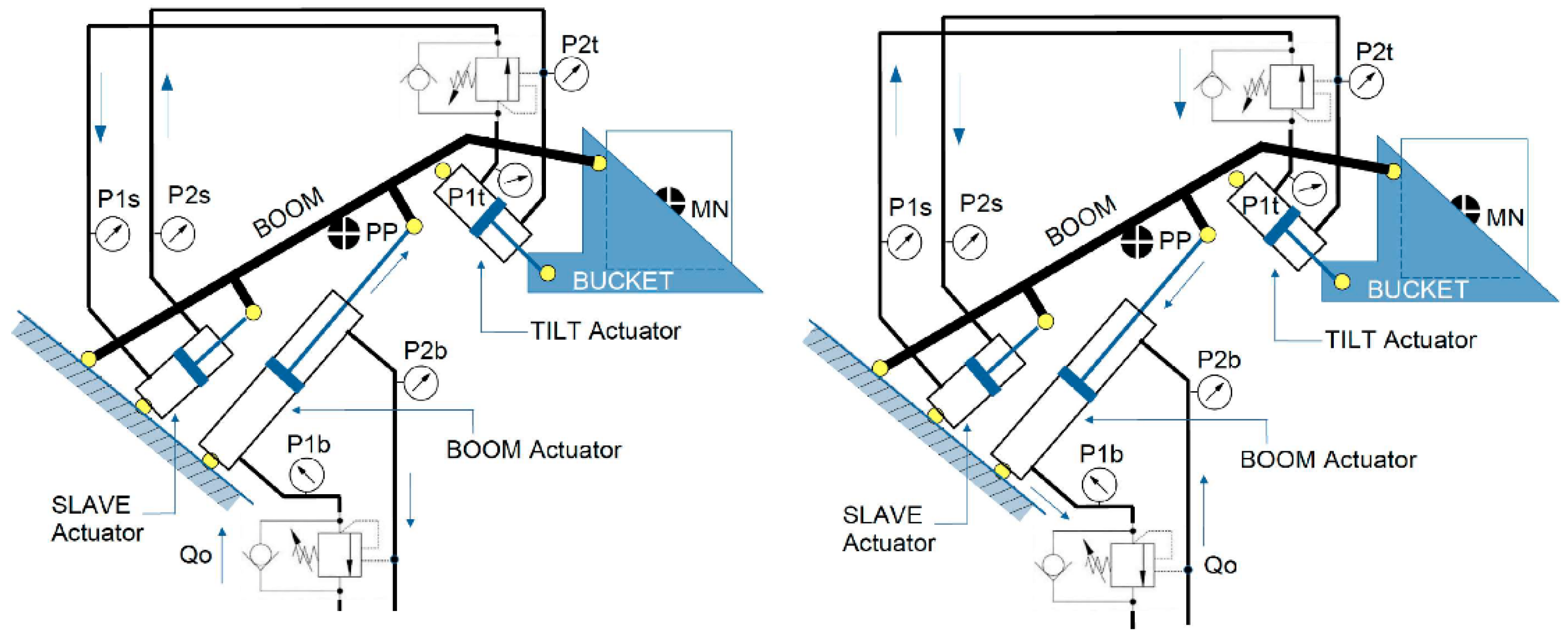
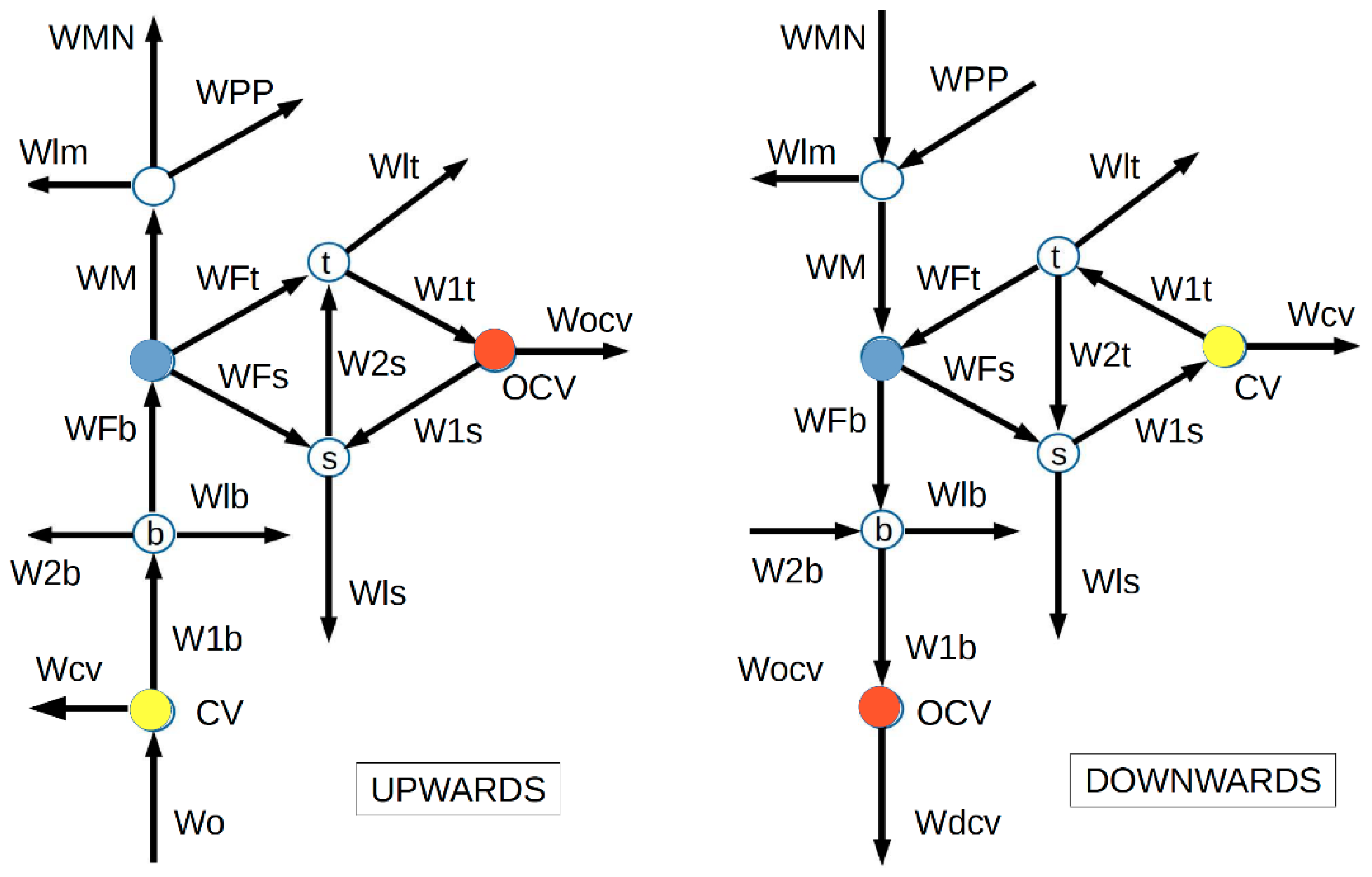
Referring to
Figure 1 (left), the energies that are involved in the upward movement of the boom cylinder moving from position
to position
can be defined as:
Analogously, referring to
Figure 1 (right), for downwards movement, the energies that are involved in the downward movement from
, are
where,
and
is area ratio of elevation actuator.
On the other hand, the energy that is transferred to the load is equal to its potential energy raising. The mass that is involved is composed of the equivalent proper mass (bucket, arm, tilt cylinder, etc.), and the nominal mass (load).
Mpp is the symbol that is related to the whole mechanism mass, and
MN points to the nominal mass.
Note that
sign modifies the incoming or outcoming potential energy.
Substituting b for its value and
Q0 for any of the two values corresponding to the up or down movement:
where
2.2. Average Energy Index
The average energy index
IWx(sei) represents the average value of the energy index of a load movement with a stroke.
As an example, to explain and develop the concepts that are proposed in this paper, the activity of raising and lowering a load has been taken as an object of study. We have considered different machines (e.g., frontal loader, telehandler, and steer skid loader) that could generically be included under the common name of loaders; all have a self-leveling bucket system.
Of all the available ones, this study examined those that present a greater didactic value and cover a wider range of possibilities. This work is based on the data that were collected over the last few years in the experimental study of machines, components, and systems. Most of them are the result of laboratory appliances and prototypes that allow the incorporation of atypical components and hydraulic circuit architectures that were specifically chosen for research purposes [
16]. It should be noted that no results came from one specific experiment with the purpose of validating the proposed KPIs. On the contrary, they are the basis for their development and, therefore, sometimes a dispersion of results may appear that would not occur in more controlled experimental conditions. We understand that this does not detract from the experimental validation, but rather adds value to its practical use in a real environment.
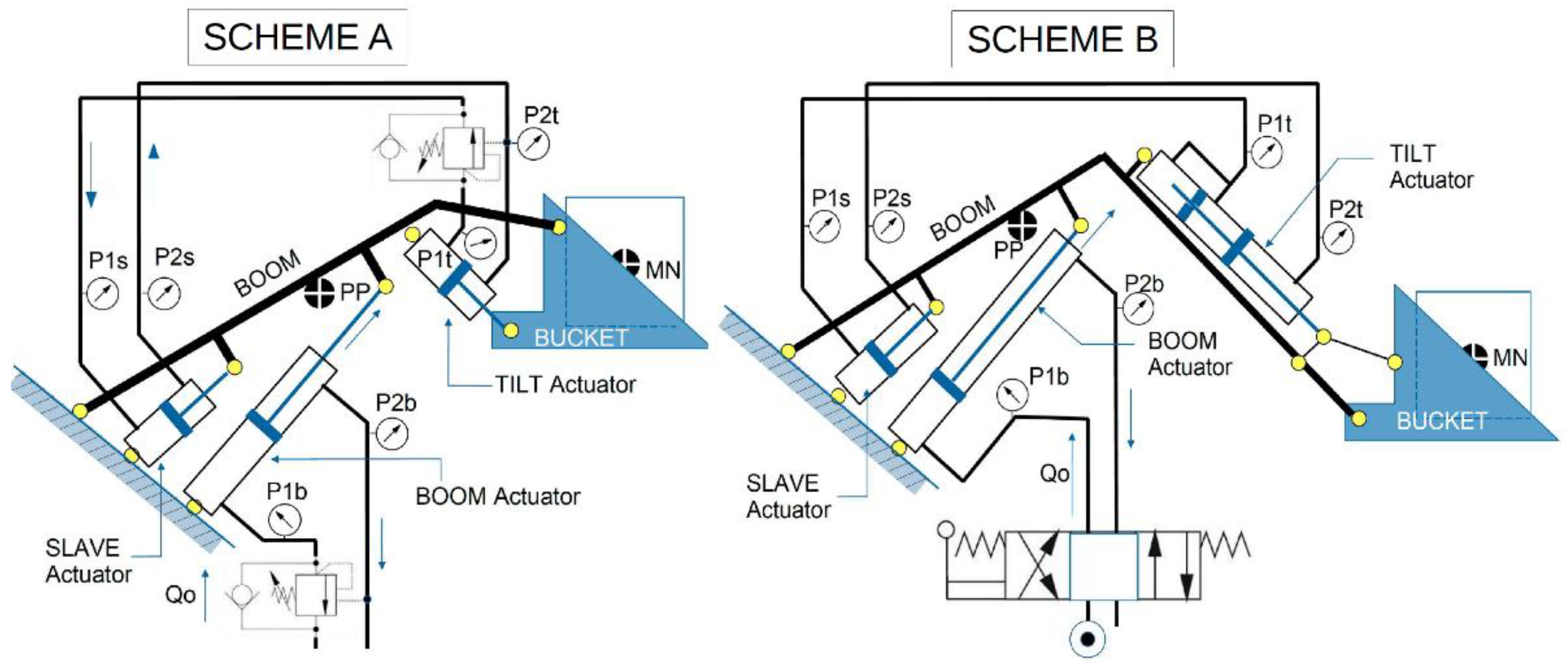
Figure 2 shows two topological schemes (A and B) that characterize the three machines that are considered. Of these, two machines are of type A and one machine of type B. For identification purposes, we named the three machines M1A, M2A, and M3B. All of them are of different sizes, even though they synchronize the bucket movement by the “slave actuator system.” In the M1A and M2A units, the boom actuator retracts when raising, and in the M3B unit, the tilt actuator extends when raising.
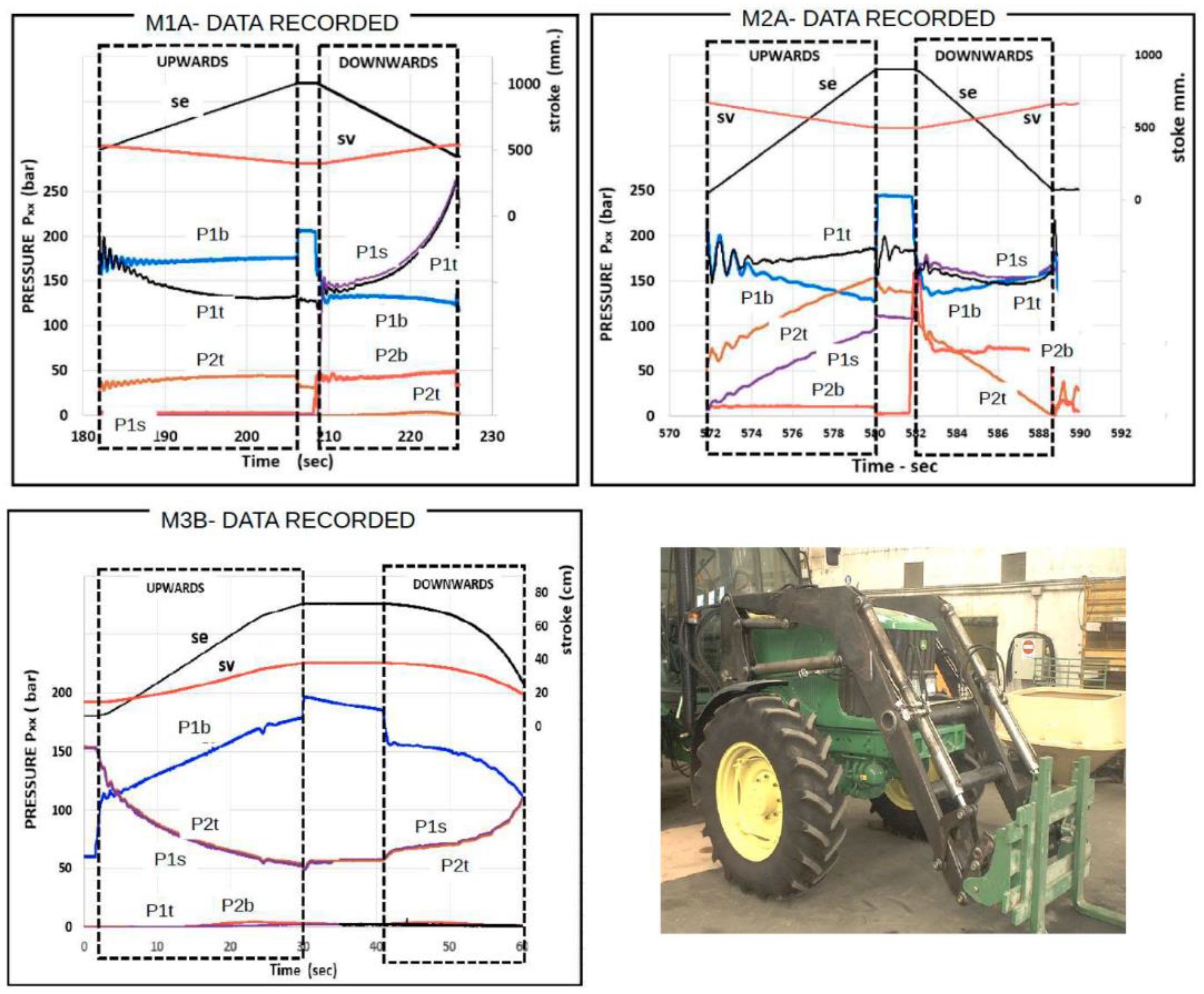
Customed hydraulic machines were instrumented at the experimental rigs that are owned at the CATMech-UPC labs. Dedicated sensors and transmitters were adapted to record the standard working cycle. Data were collected on the pressures, linear and angular positions, fluid temperatures at relevant points, and pump outflow. All were sampled at a rate of 1 kHz.
The data were collected by the RMC200 multi-axis motion controller from Delta Computer Systems, Inc.
Figure 3 shows the typical graphs of the variables that were recorded as a function of time.
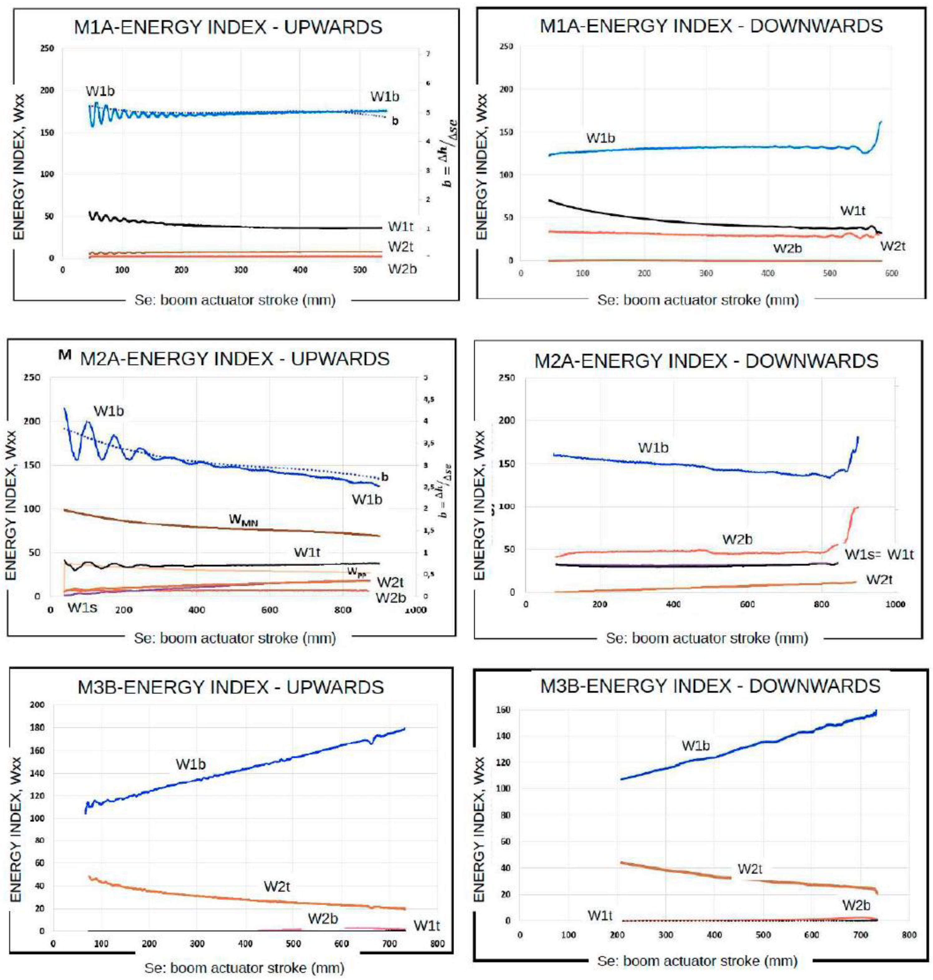
Figure 4 presents examples of the plots corresponding to the energy index,
Wx, for different types of machines. This information is kinematically given by the evolution of the parameter “b”, and hydraulically by the evolution of the energy index,
W1b, and may be condensed into a single parameter such as the slope of the adjusted trend line.
M1A: the slope of energy index
W1b is “zero”, so the load capacity remains constant with the height of the load and power consumption is stable both up and down. (
Figure 4-upper).
M2A: the slope of energy index
W1b is “negative”, so the load capacity increases with the height of the load and power consumption is higher down than up. (
Figure 4-midle).
M3B: the slope of energy index
W1b is “positive”, so the load capacity decreases with the height of the load. And power consumption is higher up than down. (
Figure 4-bottom).
The type of slope is due to the kinematics of the machine, even those that are corrected by the behaviour of pressures in the slave cylinder. This information is kinematically given by the evolution of the parameter “b”, and hydraulically by the evolution of the energy index W1b, and may be condensed into a single parameter such as the slope of the adjusted trend line.
The slope W1b curve type is important for the load capacity and power balance of the machine. It is possible to achieve energy balances with all this information.
3. Energy Balance
In
Figure 5, some diagrams are shown that intend to visualize the energy that flows through the different elements that make up the lifting system (up and down movements) according the following equations:
- 1-
Energy balance for lift cylinder
- 2-
Energy balance for tilt cylinder
- 3-
Energy balance for slave cylinder
- 4-
Conditions to be met as a result of the connections (tilt/slave actuators and overcenter/check valves)
- 5-
Energy balance through mechanical structure (boom)
These diagrams can be adapted to the M3B machine by simply removing the Wocv/Wcv arrow that represents the energy flow through the overcenter/check valves between the tilt and slave actuators. In relation to the equations of the energy balances, it is only necessary to cancel the same terms of the expressions (23) and (24).
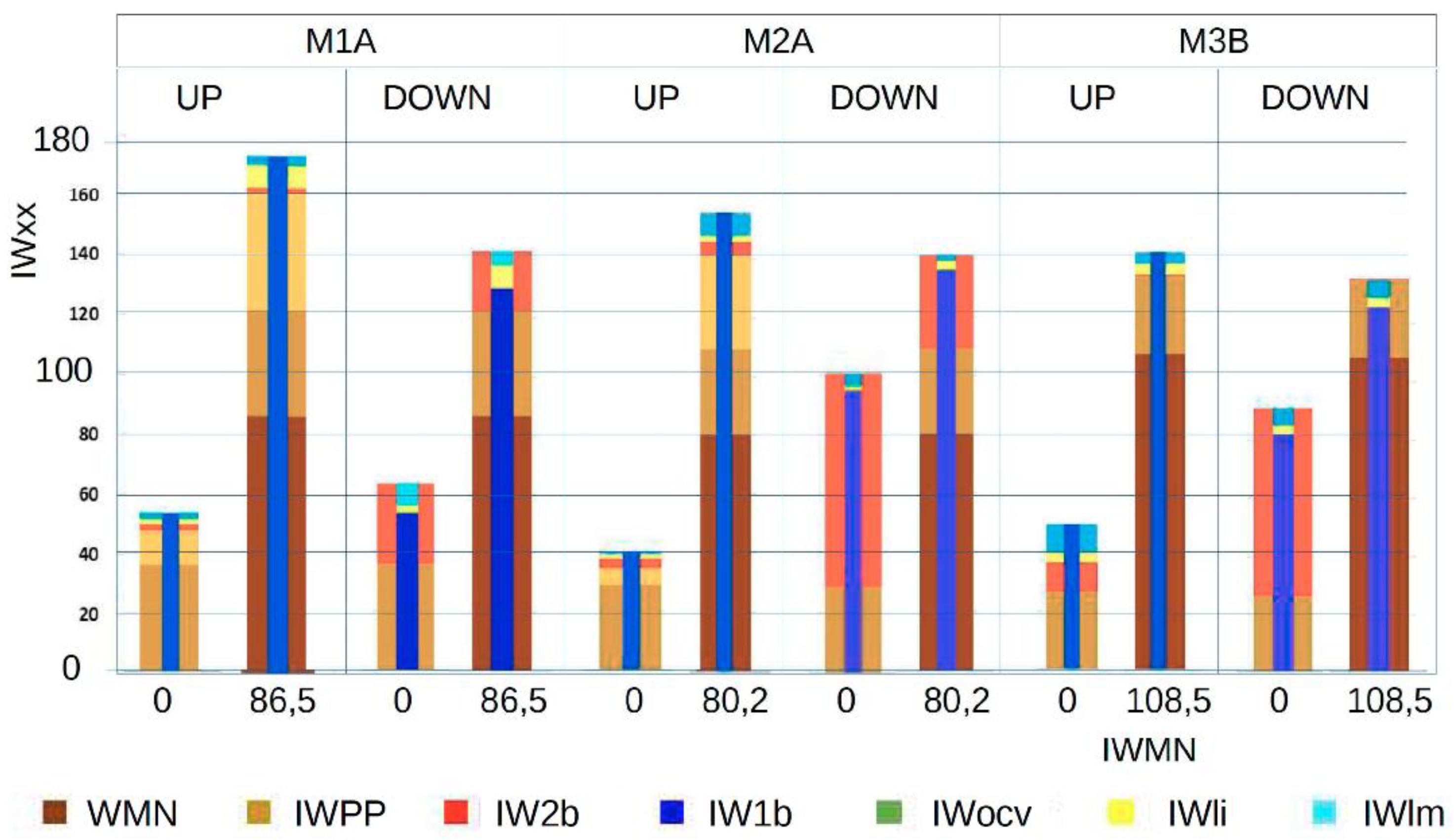
Figure 6 shows a representation of the energy balance corresponding to the upward and downward movements of the three proposed machines. This graph allows a comparison between them and visualization of how the different energy terms were used for the two values of the load.
4. Use of Average Energy Index as KPI
As mentioned in the previous section, the average energy index IWx(sei) represents the average value of the energy index of a load movement with a stroke from se1 to se2. To compare machines (from the same manufacturer or from the competition), discover weak points, and make decisions about new designs or improvements, in this paper it is proposed to use the average energy indices as key performance indicators (KPI).
For simplicity, let’s make this exercise only for the machines that are presented in this paper. At this stage is important to highlight:
All data herein that were used comes from many research activities that were carried out along huge service that was offered to customer services from CATMech infrastructures. The data corresponds to (lab and “on-field”) appliances and prototypes (research, development, and optimization activities). Each example corresponds to a complete up and down cycle, with a load constant throughout the cycle.
The analyzed data were chosen to expose the power of the average energy index and aid in the optimization of the design parameters.
The KPI index also allows for the analyzing of innovation factors in different technological fields, such as mechanical, hydraulic, control techniques, and others.
Table 1 contains the definitions of the proposed KPIs and the calculated values for each of the three mentioned machines.
4.1. Comments
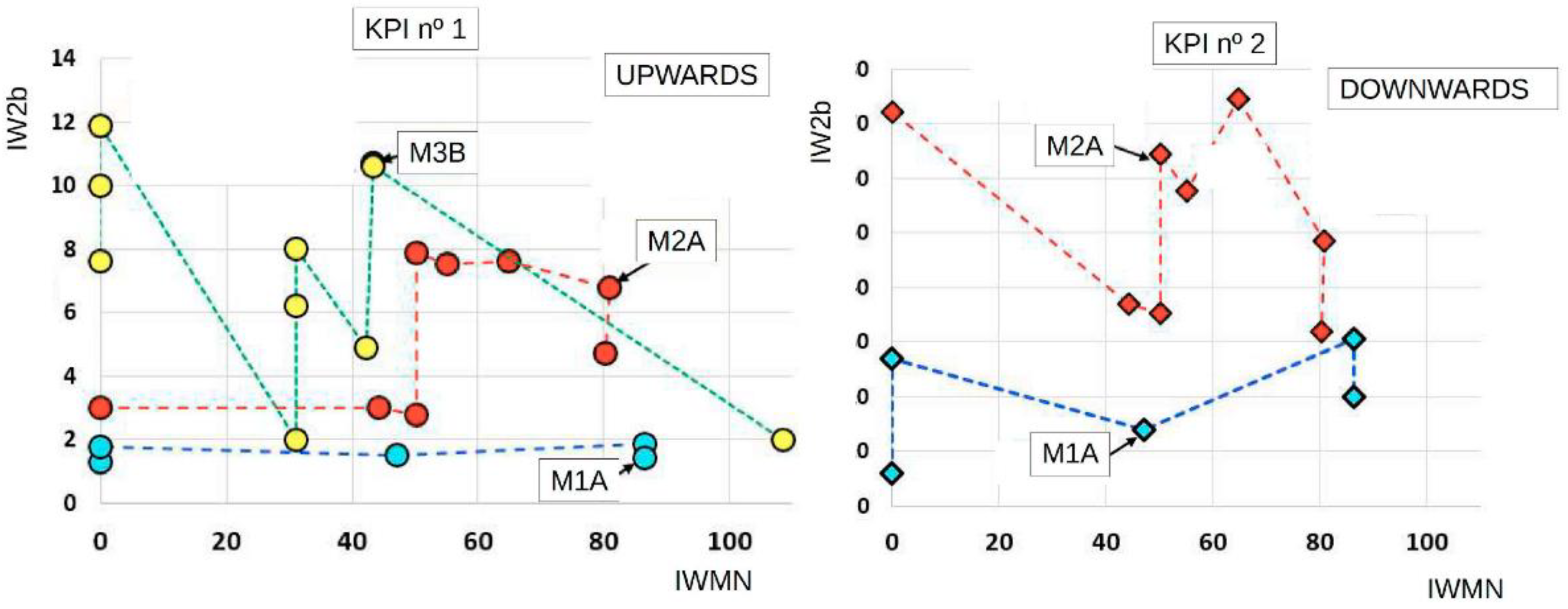
4.1.1. KPI N° 1—Comments about IW2b (Up)
The results that are presented in
Figure 7 (left), allow us to make the following considerations: M1A presents excellent values of the KPI, so the question is to consider if the cost reduction that is involved in downsizing is worth it, and how it can affect the value of this KPI, M2A and M3B present erratic values. These values correspond to different situations where the most significant variable had directional control valve metering or alternative regulation controls.
It is an indication of the return circuit impedance. In some cases, a reduced low value can be the result of a correctly designed metering spool or the result of a “standard” spool of an oversized directional control valve. As such, this indicator must be analyzed inside its context, and must be the lowest value possible with the control valve that is specifically chosen (and if it is too low, perhaps it is the occasion to reconsider if a lower valve cost is preferable).
4.1.2. KPI N° 2—Comments about IW2b (Down)
In
Figure 7 (right), is clear that the machine M1A takes advantage over M2A due to the technology that is employed. This is related to the energy that is required to lower a load, explained by the imperative requirement of using a load holding valves for safety reasons (European Directive 98/37/CE and amendments).
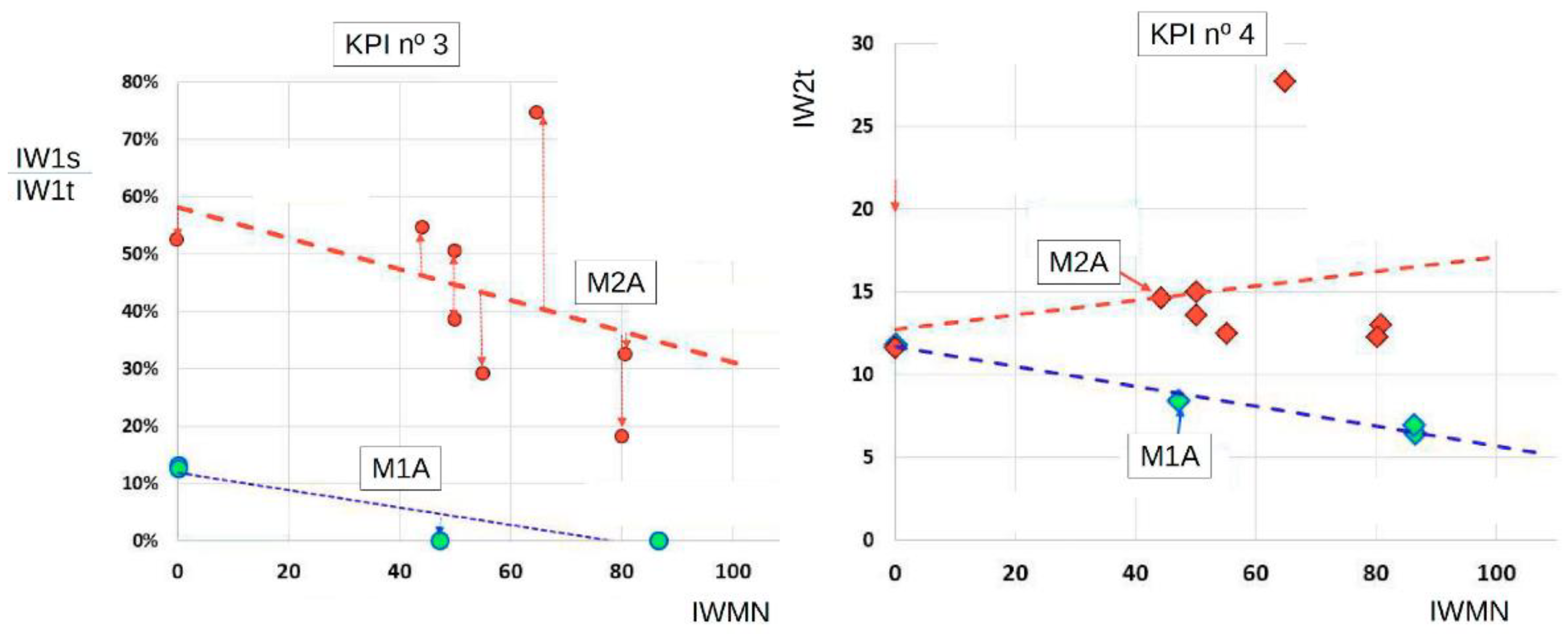
4.1.3. KPI N° 3—Comments about IW1s/IW1t
IW1s/
IW1t represents the percentage of energy that is transferred from the tilt cylinder to the slave cylinder, and this is primarily due to bucket self-levelling system design (hydraulic/mechanism). If the ratio,
kup, is less than 1, any transfer is not possible.
This is the case of M1A, where the energy that is transferred tends to be (practically) zero,
Figure 8 (left). A ratio
kup < 1 means that the flow out from the base chamber of the tilt cylinder (
Q1t) can’t fill the base chamber of the slave cylinder with the needed flow
Q1s. M2A has an average value of the KPI of approximately 45% that may be enhanced. The KPI3 must be considered together with
IW2t. which is related to the energy that is required to pilot the overcenter valve of the tilt cylinder.
4.1.4. KPI N° 4—Comments about IW2t
IW2t represents the energy that is supplied to the rod chamber of the tilt cylinder and is due to the pressure that is required to pilot the overcenter valve of the tilt cylinder. A different behavior of each curve means basic differences between machines. A ratio
kup for M1A is <1 and for M2A is >1,
Figure 8 (right).
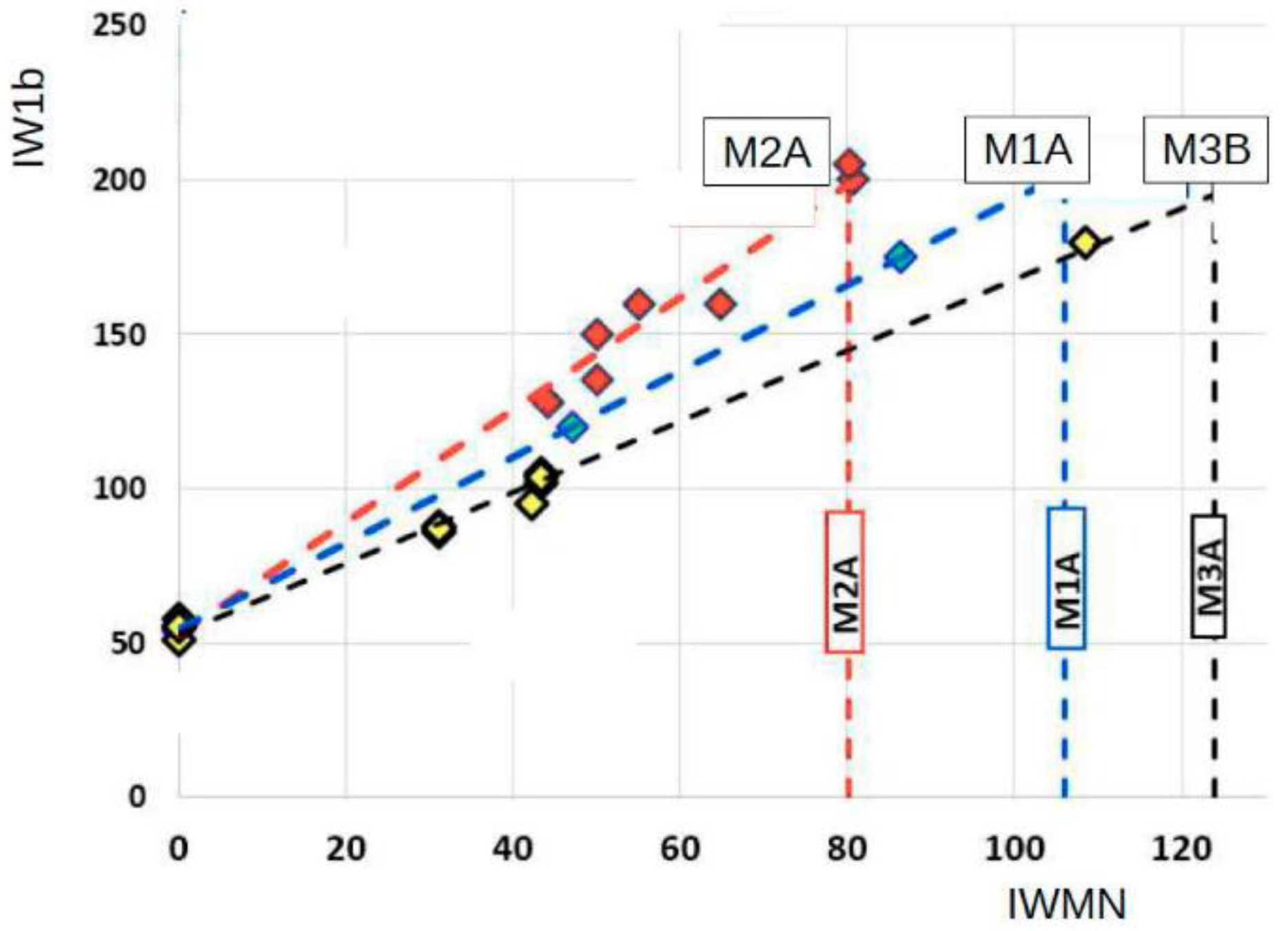
4.1.5. KPI N° 5—Comments about ΔW1b/IW1b
This index allows us to assess how Δ
W1b/
IW1b varies
W1b along the actuator stroke, as mentioned in a previous paragraph and in
Figure 5. A positive value of this indicator indicates that the machine loses lifting capacity as the boom rises.
Figure 9 shows the relationship between the maximum energy index
IW1b, and
IWMN (load to lift). The maximum energy index for M2A corresponds to the lowest position of the stroke, and for M3B, corresponds to the highest. For M1A, the energy index W1b, is nearly constant and coinciding with the average energy index
IW1b. M2A did not utilize all its load capacity due to the kinematic design of the mechanism. Also, M3B, with a lower level of losses, had a higher load capacity because it has a best kinematic design, a lighter mechanical structure, and does not incorporate overcenter valves.
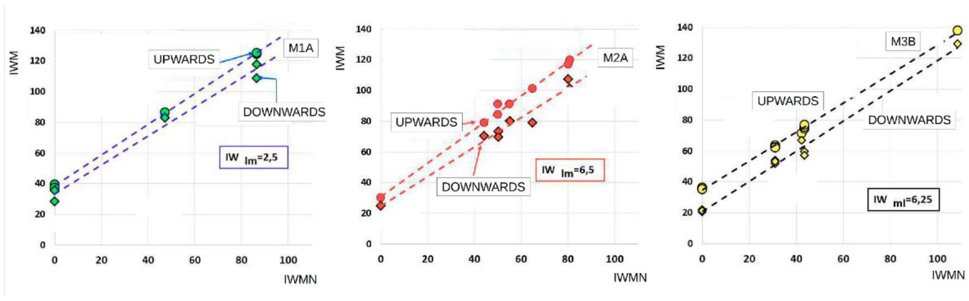
4.1.6. KPI N° 6—Comments about IWM
Figure 10 shows the
IWM that is related with the energy that is used in raising its own weight. Its value remains constant in the energy balance of each machine, both for the rise and the descent and regardless of the nominal load that is raised.
4.1.7. KPI N° 7—Comments about IWpb
As can be seem in the
Figure 6, machine M3B, has a lower index value as it corresponds to a lighter structure, and M1A and M2A have similar values, as they correspond to two machines that were designed under similar topologic designs, even if the size is different. If, eventually, the study would include other machines with a lower index value, it would mean that the manufacture technology could result in a lighter structure and could be the object of consideration and study. The utility of using dimensionless indicators is that the design technologies can be compared between different machine sizes.
4.1.8. KPI N° 8—Comments about IWlm
Figure 10 shows the evolution of
IWM (load), corresponding to the up and down movement, respectively. The difference between them is mainly due to the structural friction between the parts of the machinery that are associated with the movement.
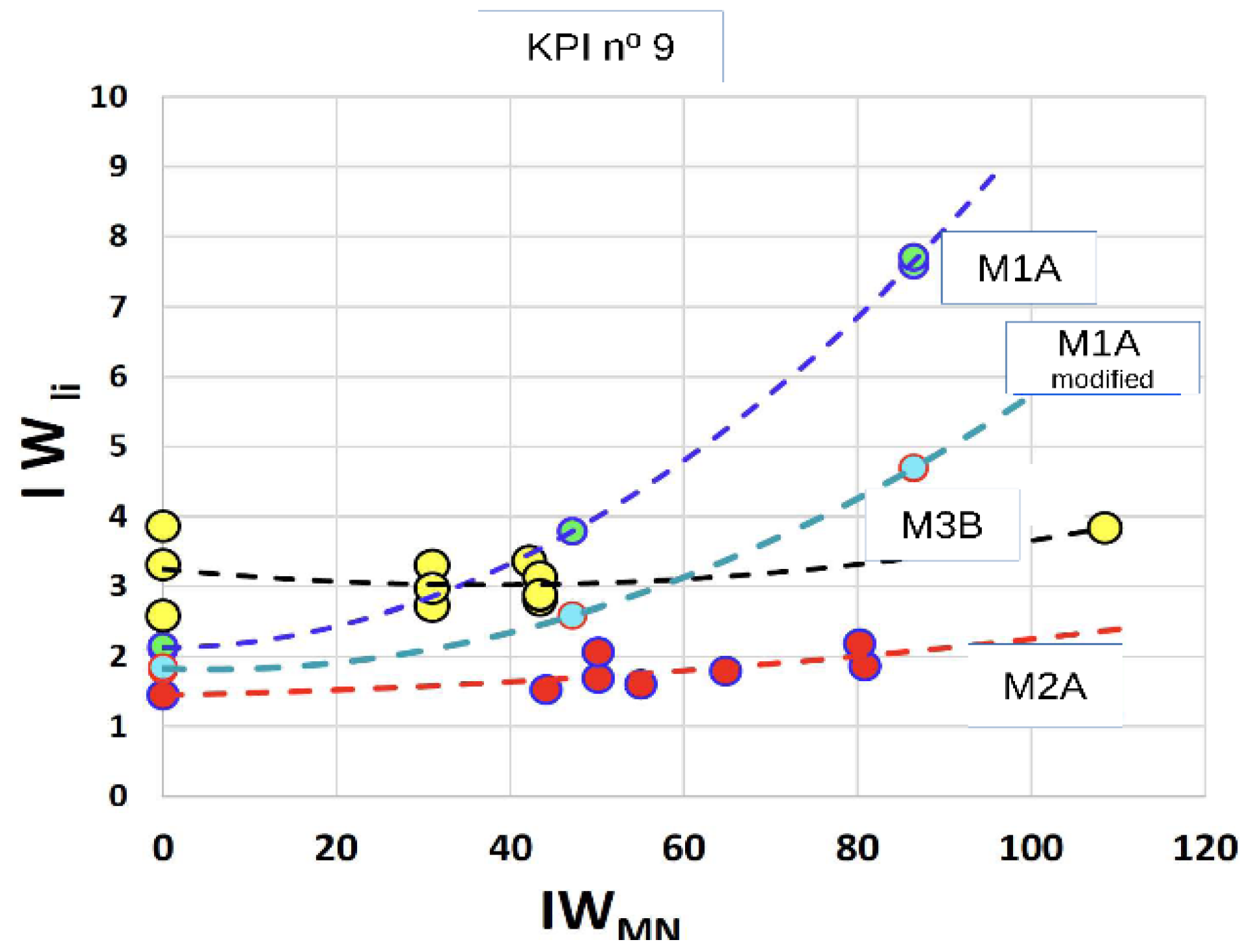
4.1.9. KPI N° 9—Comments about IWli
Higher losses of M1A, are due to friction due a misalignment of the tilt cylinder (modified to incorporate an internal pressure sensor) during its assembly process in the lab, carried out by university personnel. Even though this misalignment was corrected when it was verified, it has been considered appropriate to choose these data for their didactic value, see
Figure 11.
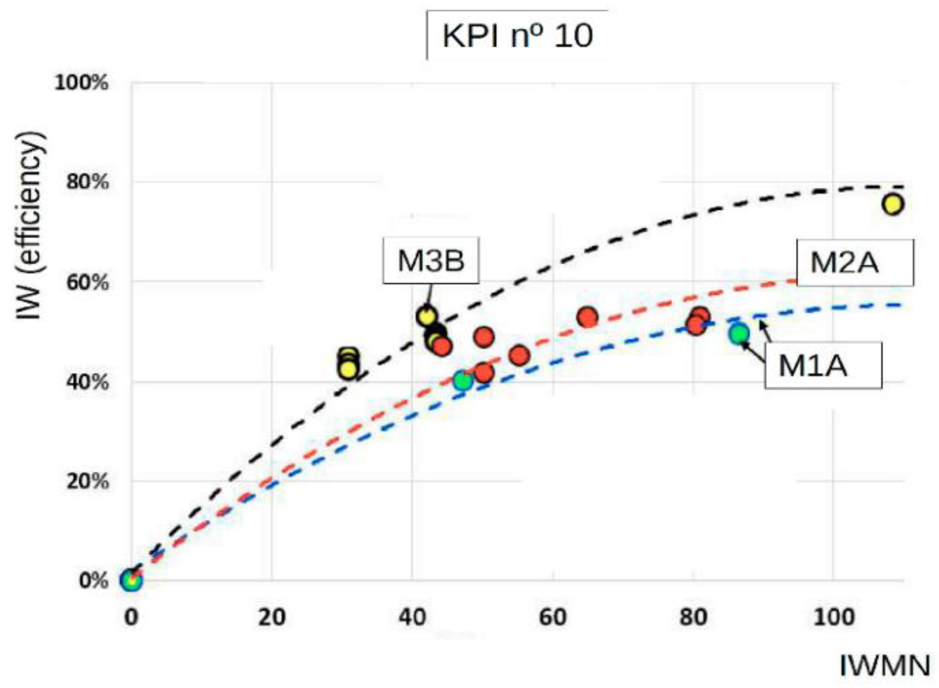
4.1.10. KPI N° 10—Comments about Efficiency
Complementing the proposed dimensionless KPI’s with the classic overall efficiency, it is possible to have a framework that allows for monitoring and decision-making in the process of an energy improvement of the machine, see
Figure 12.
Clearly, the machine M3B, has better efficiency, due to its lighter structure and simpler hydraulic circuit without the losses that are inherent to the overcenter valves. Even when there is a certain space by improving its KPI’s: IW2b and IWlm. Also, M1A and M2A, as expected, had lower efficiencies, with an improvement path through proposed KPI’s.
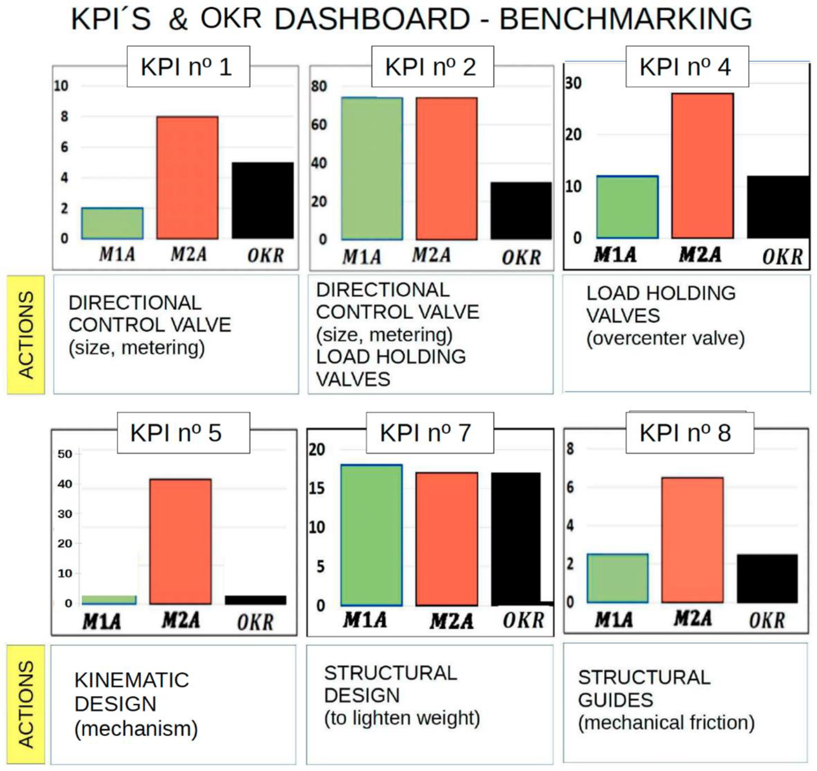
5. KPI’s Analysis (DASHBOARD)
Presenting KPIs on a dashboard has become the most popular way to display and use them as a decision-making tool. Any provision is good if it serves this purpose. As an example,
Figure 13 presents a simple dashboard which includes the values of the indicators with the objectives and the improvement actions.
A first look at the efficiency graph (
Figure 12) would lead us to an obvious first conclusion: the machine M3B is the most efficient of the three. This machine does not have some of the losses that are inherent in the M1A and M2A designs, such as those that are associated with overcenter valves as well as a lighter structural design.
On the other hand, comparing the efficiency of the M1A and M2A machines, we may be tempted to consider M2A slightly better (slightly higher efficiency). However, a detailed analysis of
Figure 13, the values of the proposed KPIs that are shown indicate that the M2A has a high potential for improvement.
The simple principle that “if the M1A design has better indicators, the M2A design should also be able to achieve them”. We refer to, for example, KPIs 1, 2, 4, and 5. That is to say, the energy indices IW2b (up), IW2b (down), IW1t, and the ratio ΔW1b/IW1b are candidates for improvement.
Obviously, meeting these challenges may not be that simple, but it clearly indicates that these key points require the attention of designers, either to improve this machine design or for a future new prototype.
6. Conclusions
This article reports a comprehensive explanation of a new methodology that is based on a set of KPI indicators to evaluate the opportunities for improvements in mobile machines. These indicators can be deduced quickly from simple energy balances using dimensionless parameters (energy index and average energy index). The example has been carried simulating the tasks of raising and lowering different loads to develop the concepts that are proposed herein.
A list of key performance indicators (KPIs) is proposed. These indicators are subcategorized according to the design and manufacture of the mechanical and hydraulic system, the control strategies, and others. All KPIs and their corollaries are reviewed concisely. The findings that were obtained from experimental results that were relevant to this study are given as a simple KPI’s and OKR dashboard (Benchmarking), which includes the values of the indicators with the objectives and improvement actions.
This methodology can apply to a wide range of similar machinery independent of nominal size (of the same brand or competitors) as dimensionless parameters. The systematic application of this methodology should generate a “KPI’s database” from which the following milestones can be determined:
- 1-
Acquire a table of reference values (statistically significant and achievable). These values highlight the current state of the art technology concerning energy efficiency and the level of maturity of the technologies that are involved.
- 2-
Expand and prioritize the list of indicators that highlight the evolution of improvement and innovation and the technologies that make it possible
- 3-
Define the design criteria and recommendations that allow estimating the mechanical and hydraulic friction into others, and then what can we expect (or extrapolate) from a new prototype.
Addressing these milestones will be the subject of future research.
Author Contributions
The investigation was led and supervised by E.C. and P.R. Experimental works, models, data processing, and illustrations were completed by G.R., L.J.B., P.R., P.-J.G.-M. and E.C. The manuscript was finalized by G.R., E.C., P.R. and P.-J.G.-M. All authors have read and agreed to the published version of the manuscript.
Funding
This research received external funding. Data of the front loader originated in the prototype that was built up by BMH during the research activities in the framework of PROHIPP project, partially financed by EU (2004–2008), and LEVANTE project, partially financed by IBEROEKA program (2002–2005).
Institutional Review Board Statement
Not applicable.
Informed Consent Statement
Not applicable.
Data Availability Statement
The data presented in this study are available on request from the corresponding author. The data are not publicly available due to privacy reasons.
Acknowledgments
Our gratitude to the entities that have lent their machines to evaluate their behavior, during our R&D activities, especially AUSA (Manresa-Spain) and Palas BMH (Poleñino-Spain). Also, the Roquet Group and IHBER, who provided important hydraulic devices that were used in the research. Part of this research was dedicated to investigating the influence and contribution to the behavior of the machine of different components and systems designs. These investigations and data have been the trigger for the modelling of the proposed KPIs and the basis their validation.
Conflicts of Interest
The authors declare no conflict of interest.
Nomenclature
| A | (for rod side) |
| CV | Check valve |
| Δh | Specific potential energy change |
| Δt | Time interval |
| F | Load at the actuator, e.g.,: Fs slave actuator load |
| g | Gravity acceleration |
| IW | Average energy index |
| M | Mass |
| Mpp | Own mass, including bucket or fork |
| Mpb | Own mass, excluding bucket or fork |
| MN | Load mass |
| OCV | Overcenter valve |
| P | Pressure |
| Q | Flow rate |
| SMART | Specific, Measurable, Achievable, Relevant, Timely |
| se | Rod position |
| W | Energy index, e.g., W1b energy index related with piston side chamber of the boom actuator |
| The subscripts refer to the object, location, or situation under consideration |
| 1 | Piston side chamber of cylinder |
| 2 | Rod side chamber of cylinder |
| b | Boom actuator |
| i | Internal hydraulic losses |
| l | Losses, e.g.: lm, frictional mechanical losses; li, internal hydraulic losses |
| m | Mechanical |
| s | Slave actuator |
| t | Tilt actuator |
| x | Generic reference |
References
- European Commission. COM(2010) 2020 Final, Europe 2020: A Strategy for Smart, Sustainable and Inclusive Growth. Available online: http://eur-lex.europa.eu/LexUriServ/LexUriServ.do?uri=COM:2010:2020:FIN:EN:PDF (accessed on 11 January 2022).
- Karpenko, M.; Bogdevičius, M. Review of Energy-saving Technologies in Modern Hydraulic Drives. Moksl.-Liet. Ateitis 2017, 9, 553–558. [Google Scholar] [CrossRef] [Green Version]
- Yu, Y.; Jeong, E.; Ahn, K.K. Review of Energy Saving Technology of Hybrid Construction Machine. J. Drive Control 2018, 15, 91–100. [Google Scholar] [CrossRef]
- Berne, L.J.; Raush, G.; Gamez-Montero, P.J.; Roquet, P.; Codina, E. Multi-Point-of-View Energy Loss Analysis in a Refuse Truck Hydraulic System. Energies 2021, 14, 2707. [Google Scholar] [CrossRef]
- Roquet, P.; Gamez-Montero, P.; Castilla, R.; Raush, G.; Codina, E. A Simplified Methodology to Evaluate the Design Specifications of Hydraulic Components. Appl. Sci. 2018, 8, 1612. [Google Scholar] [CrossRef] [Green Version]
- Mahato, A.C.; Ghoshal, S.K. Energy-saving strategies on power hydraulic system: An overview. Proc. Inst. Mech. Eng. Part I J. Syst. Control Eng. 2021, 235, 147–169. [Google Scholar] [CrossRef]
- Greenwood, R.G. Management by Objectives: As Developed by Peter Drucker, Assisted by Harold Smiddy. Acad. Manag. Rev. 1981, 6, 225. [Google Scholar] [CrossRef]
- Deming, W.E. Out of the Crisis, 1st ed.; MIT Press: Cambridge, MA, USA, 1986; ISBN 0-911379-01-0. [Google Scholar]
- Brim, R. A Management by Objectives History and Evolution. Available online: http://www.performancesolutionstech.com/FromMBOtoPM.pdf (accessed on 11 January 2022).
- Hansen, B. KPIs vs. OKRs: How They Compare and Why You Need Both to be Successful. Available online: https://www.wrike.com/blog/kpis-vs-okrs-compare-need-successful/ (accessed on 28 January 2022).
- Lindberg, C.-F.; Tan, S.; Yan, J.; Starfelt, F. Key Performance Indicators Improve Industrial Performance. Energy Procedia 2015, 75, 1785–1790. [Google Scholar] [CrossRef] [Green Version]
- May, G.; Barletta, I.; Stahl, B.; Taisch, M. Energy management in production: A novel method to develop key performance indicators for improving energy efficiency. Appl. Energy 2015, 149, 46–61. [Google Scholar] [CrossRef] [Green Version]
- May, G.; Taisch, M.; Prabhu, V.V.; Barletta, I. Energy related key performance indicators–state of the art, gaps and industrial needs. In IFIP International Conference on Advances in Production Management Systems; Springer: Berlin/Heidelberg, Germany, 2013; pp. 257–267. [Google Scholar] [CrossRef] [Green Version]
- Osman, M.; Abokersh, M.H.; El-Baz, O.; Sharaf, O.; Mahmoud, N.; El-Morsi, M. Key performance indicators (KPIs): Assessing the process integration of a shell-and-tube latent heat storage unit. J. Clean. Prod. 2020, 256, 120249. [Google Scholar] [CrossRef]
- Tambare, P.; Meshram, C.; Lee, C.-C.; Ramteke, R.J.; Imoize, A.L. Performance Measurement System and Quality Management in Data-Driven Industry 4.0: A Review. Sensors 2021, 22, 224. [Google Scholar] [CrossRef]
- Rivas, J.R. Accionamiento y Control del Posicionado de Aperos Agrícolas Mediante Actuadores Oleo Hidráulicos. Ph.D. Thesis, Universitat Politècnica de Catalunya, Terrassa, Spain, 2004. [Google Scholar]
| Publisher’s Note: MDPI stays neutral with regard to jurisdictional claims in published maps and institutional affiliations. |
© 2022 by the authors. Licensee MDPI, Basel, Switzerland. This article is an open access article distributed under the terms and conditions of the Creative Commons Attribution (CC BY) license (https://creativecommons.org/licenses/by/4.0/).


 ,
, 


