Review

Compact Thermal Storage with Phase Change Material for Low-Temperature Waste Heat Recovery—Advances and Perspectives

by
Daniela Dzhonova-Atanasova
1,
Aleksandar Georgiev
1,2,*,
Svetoslav Nakov
1,
Stela Panyovska
1,
Tatyana Petrova
1 and
Subarna Maiti
3
1
Institute of Chemical Engineering, Bulgarian Academy of Sciences, Acad. G. Bonchev Str., Bl. 103, 1113 Sofia, Bulgaria
2
Department of Mechanics, Plovdiv Branch, Technical University of Sofia, 25 Tsanko Diustabanov Str., 4000 Plovdiv, Bulgaria
3
CSIR-Central Salt & Marine Chemicals Research Institute, Gijubhai Badheka Marg, Bhavnagar 364002, Gujarat, India
*
Author to whom correspondence should be addressed.
Energies 2022, 15(21), 8269; https://doi.org/10.3390/en15218269
Submission received: 30 September 2022 / Revised: 24 October 2022 / Accepted: 28 October 2022 / Published: 5 November 2022
(This article belongs to the Collection Advances in Heat Transfer Enhancement)

Abstract

:
The current interest in thermal energy storage is connected with increasing the efficiency of conventional fuel-dependent systems by storing the waste heat in low consumption periods, as well as with harvesting renewable energy sources with intermittent character. Many of the studies are directed towards compact solutions requiring less space than the commonly used hot water tanks. This is especially important for small capacity thermal systems in buildings, in family houses or small communities. There are many examples of thermal energy storage (TES) in the literature using the latent heat of phase change, but only a few are commercially available. There are no distinct generally accepted requirements for such TES systems. The present work fills that gap on the basis of the state of the art in the field. It reviews the most prospective designs among the available compact latent heat storage (LHS) systems in residential applications for hot water, heating and cooling and the methods for their investigation and optimization. It indicates the important characteristics of the most cost- and energy-efficient compact design of an LHS for waste heat utilization. The proper design provides the chosen targets at a reasonable cost, with a high heat transfer rate and effective insulation. It allows connection to multiple heat sources, coupling with a heat pump and integration into existing technologies and expected future scenarios for residential heating and cooling. Compact shell-tube type is distinguished for its advantages and commercial application.

1. Introduction

The compactness of the thermal energy storage unit is one of the issues in a small system for domestic heating or cooling using low-temperature thermal energy as a source. Despite the intensive research in this area and the great number of suggested designs and materials for that purpose, there are few compact designs that are close to the commercial stage. Sources of low-temperature heat are abundant, including renewable heat sources, as well as waste heat from combustion of fossil fuel and industrial processes and activities. Waste heat with a temperature level below 200 °C is usually referred to as low-temperature waste heat. In Europe, it is about a third of the waste heat potential [1]. At the same time, there are issues hindering effective low-temperature waste heat recovery, such as limited availability of suitable user demand and mandatory minimization of heat loss. Heat-to-power conversion is not efficient for low-temperature waste heat, but direct use for domestic heating is still one of the most commonly used options [2].
One of the strategies for reduction in greenhouse gas emissions, suggested in Ref. [3], is transition from individual generators to district heating (DH) networks. It is expected that such a scenario can achieve the target, defined by EC, of reaching an 80% reduction in annual emissions by 2050, compared to the levels in 1990, but also at a lower cost for heating and cooling than the current solutions [4,5]. The heat market for buildings in 2010 in the EU (27 countries) was dominated by fossil fuels in onsite boilers, while the share for DH was only 13% [5]. Figure 1 presents the chronology of development of the DH with the main characteristics of the generations. The modern fourth generation of district heating (4GDH) networks ensure high efficiency at low temperatures (30–70 °C) and absence of supply or demand peaks, which is achieved by integration of efficient thermal storage systems. The 4GDH combines conventional boiler systems, waste heat recovery and renewable energy sources for intelligent control of network performance [6,7].
The 5GDH permits an even lower distribution temperature (0–30 °C), neutral for thermal losses [8]. It requires a booster heat pump at the consumer site [9]. In addition to the characteristic of the 4GDH, it allows bi-directional modes—both heating and cooling. In the 4GDH and 5GDH, integration of efficient TES systems is mandatory. They allow high efficiency at low temperatures and absence of supply or demand peaks [7]. They solve the problems with fluctuations in the connected multiple renewable or waste heat sources and the mismatch of supply and demand in time, place and temperature level. A review [10] explores the current state and the future perspectives of implementation of TES in DH networks. Important issues connected with TES systems are identified: increased investment costs (the cost of small-scale TES being more highly related to stored thermal energy than the cost of large-scale TES); dedicated space, especially large for seasonal TES; thermal losses during the storage process; difficulties related to system design and connection planning and lack of supportive legislation. Sensible heat storage using water as a storage medium is most often used as daily or seasonal heat storage with DH. Daily storage is usually a tank filled with water. Weekly or seasonal storage uses tanks, pits, aquifers and boreholes.
A study [11] proposes using waste heat recovery in low-temperature DH networks as an alternative to a domestic heat pump, which has gained interest recently. The authors perform a techno-economic and environmental analysis of the alternatives for the planning of heating of urban neighborhoods considering Nordic conditions. The sources of waste heat are data centers, supermarkets and ice rinks. The results demonstrate an advantage of waste heat recovery in DH, which can substantially reduce strain on the electricity sector, fossil fuel dependence and CO2 emissions.
The motivation of the present review is the lack of clarity in the literature regarding the parameters of optimal design and performance of compact TES units for low-temperature heat sources. It attempts to fill that gap and to suggest the most prospective future direction of development of LHS technology, considered as one of the most prospective for domestic hot water, heating and cooling. This is achieved by critical evaluation and comparison of the available TES systems in DH and other residential applications and the most promising methods for their investigation and optimization.

2. Waste Heat Recovery

2.1. Waste Heat from Industrial Processes

A methodology for assessment of waste heat potential in Europe is suggested and demonstrated in Ref. [1]. The results for different industries in 2015 are shown in Table 1. Energy consumption in the industrial sector in the EU (28 countries) was about 3200 TWh per year, and almost the same in the residential sector, representing about 26% of the total consumption in the EU (processed from Eurostat for 2015). The total waste heat potential in the EU was 16.7% of the industrial consumption of process heat and represented 9.5% of the total industrial energy consumption, its largest part being within the 100–200 °C range. Waste heat below 100 °C was minor, while significant quantities existed within the 200–500 °C range (Table 1). In Bulgaria (2015), the industrial waste heat potential was about 2.3 TWh/year, more than 65% in the range 100–200 °C (in non-ferrous metal industry; chemical industry; non-metallic mineral industry; food industry; pulp industry; other) [1].
The potential sources of industrial low-grade waste heat are identified in Ref. [12]. The most common of them across all industrial sectors are flue gas from boilers, waste heat from compressor cooling systems and condensate from steam heating and from spent cooling water. The options for low-grade heat utilization are: (i) producing electrical power; (ii) heating; (iii) cooling; (iv) heating, cooling and electricity simultaneously; (v) producing fresh water and (vi) producing hydrogen [2]. The state-of-the-art technologies that are developed based on the concept of thermodynamic cycles for low-grade heat recovery are summarized in Ref. [12] according to the basic process enabling heat utilization as follows: vapor compression, adsorption, absorption, liquid desiccant systems, organic Rankine cycles and Kalina cycles.
Our attention is focused on technologies for waste heat recovery for DH and residential applications. In Ref. [13], special attention is drawn to the method of recovering low-temperature waste heat by cooling exhaust gases below dew point temperatures, at which point moist gas mixture begins to condense as it is cooled down at a constant pressure. Condensation recovery can be performed by direct and indirect contact (by solid heat transfer surface) between the fluids. An example of direct heat recovery is a contact economizer system with a packed column [14]. This type of system can recover up to 13–15% extra heat, which results in the same percentage of fuel economy and can heat water up to 63 °C for DH. Such systems are included in the best practices; however, they are relatively scarcely used when compared to the indirect type [15].
Recently, in major cities, there are sources of waste heat that are gaining increasing importance for DH and residential heating and cooling, the most promising described in the section below.

2.2. Waste Heat from Data Centers and Supermarkets

The DH systems typically use as a main source of heat combined heat and power plant (CHP). The data centers are indicated [16] as the second most significant secondary heat source for DH in London after industrial waste heat. The data centers include buildings hosting IT equipment, which store or process information from computer networks. They use at least 1% of the total global electricity demand, and their consumption is expected to increase rapidly [17]. Most of the electricity used by the IT equipment is turned into heat. Proper operation of servers and other IT devices requires constant air temperature and humidity, maintained by a cooling system. The latter uses about 38% of the total electricity demand of a data center [17], and the removed heat is discharged usually to the ambient air. The temperature of the waste heat varies between 10 and 60 °C depending on the kind of cooling fluid, air or water, as well as on the temperature of the cooled electronic components. As early as 2010, the water cooling the servers of a 2 MW data center provided heat for 500 homes or 1000 flats in Helsinki, Finland, where the winter temperatures often drop to −20 °C [18].
Supermarkets are considered [19] as suitable potential sources of waste heat in 4GDH and 5GDH. Their refrigeration systems discharge heat to the environment all year and are situated close to residential areas with high heating demand. Utilization of their excess heat in DH is suitable, especially when the refrigeration system operates with transcritical CO2 as a refrigerant and when the temperature of the exhaust heat is significantly above the ambient temperature compared to systems with conventional refrigerants [19].

3. LHS in DH and Other Residential Applications

Based on a review of TES in DH [10], the state-of-the-art thermal storage for low-temperature heat sources can be classified by different criteria (principle of thermal storage, storage duration, location in consumer network and distance from source) as follows (Figure 2):
The advantages and disadvantages of the three thermal energy storage principles can be observed from their typical parameters (Table 2), which have not changed much for the past 10 years. It is shown in Table 2 that TES with phase change material (PCM) has higher efficiency than the conventional hot water storage at a comparable cost. The PCM absorbs or discharges a substantial amount of thermal energy during the phase transition period at a specific working temperature. Due to their higher energy storage density, compared to sensible TES, LHS systems with PCM need less storage material to absorb a certain amount of energy, which allows more compact units.
TES with PCM is more commonly used for short-term storage of waste heat than for long-term storage [2]. The TES should cover, on average, 2–8 h in larger cities and 6–48 h in smaller cities. This type of short-term storage can balance the electricity grid and handle fluctuating low-temperature heat sources [5].

3.1. Phase Change Materials

There is significant variety in PCMs suggested and studied in the literature. Their classification is shown in Figure 3. They are selected for a certain application by appropriate temperature of phase transition and latent heat. Solid–liquid phase transition is more practical for use in TES than liquid–gas because the latter needs large volumes or high pressure for the gas phase. The available PCMs and their potentials for latent heat storage are discussed in Ref. [21]. The most essential disadvantage of organic PCMs is poor thermal conductivity (from 0.1 to 0.7 W/mK). Many studies are dedicated to enhancement in thermal conductivity of PCMs by encapsulation and/or additives of high conductivity, mainly from graphite, graphene and metal in the form of particles, nanotubes, strips, foams and matrices. Among the organic PCMs, paraffin is distinguished for its availability and low cost, combined with properties convenient for many applications. This is the reason for the very wide usage of paraffin as PCM in TES and other advanced thermal systems [22]. The main shortcomings of paraffin are the relatively low specific heat capacity, low heat transfer coefficient on the wax side and high exergy losses.
Inorganic PCMs, such as salt hydrates, possess higher thermal conductivity at substantial latent heat of fusion. Their application should take into account some problems with phase separation and subcooling effects [23] at continuous cycling of heating and cooling, which lead to a decrease in storage capacity. A commercially available compact LHS uses salt hydrates [24,25].
Eutectic PCMs are eutectic mixtures of two or more PCMs, with phase transition at lower temperature than each of the components, e.g., eutectic water-salt solutions [21], eutectic salts or metal alloys.
The LHS solutions for low-temperature waste heat are distinguished for their very wide range of application and future perspectives for heating and cooling in residential buildings [26]. They can be connected as distributed units in DH, as well as in individual heat generation systems with renewable, waste or conventional energy sources.
The systems for low- and middle-temperature heat storage are mainly of indirect type, with a solid wall separating the heat transfer fluid (HTF) and the PCM. The configurations are two types [27]: compact (generally shell-tube) and encapsulated. Of the different designs of LHS systems available in literature, over 70% of papers consider shell-tube systems [26]. They have the advantage of minimal heat loss. The HTF in shell-tube type is most often water. The encapsulated LHS systems have containers with PCM immersed in the HTF (air or water). An LHS with encapsulated PCM usually contains a greater component of sensible heat storage than a shell-tube LHS system over the same temperature range.

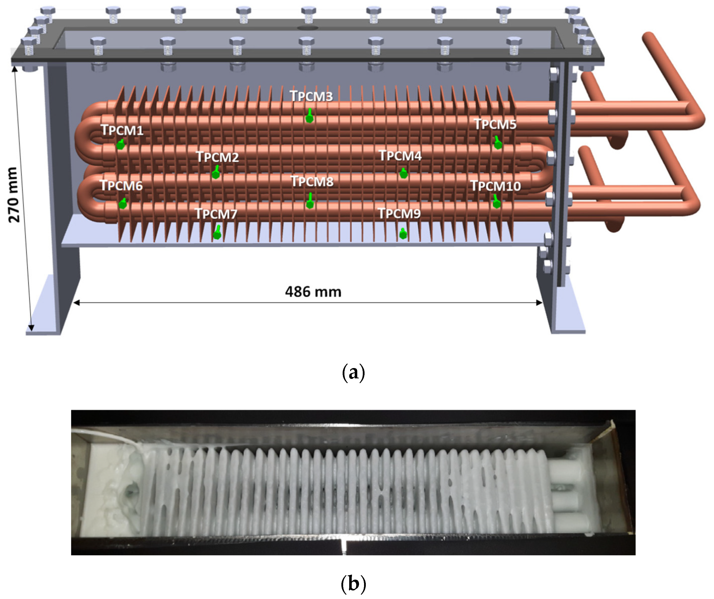
3.2. Shell-Tube Design

Figure 4 and Figure 5 illustrate the typical configurations of the shell-tube type LHS: cylindrical (Figure 4) [28] and rectangular (Figure 5) [29]. A rectangular shell-tube design (Figure 5) is proposed in Ref. [29] for industrial waste heat recovery/storage systems within the temperature range 90–100 °C (waste steam and condensate in autoclave and preheating of feed water). It consists of a stainless-steel cuboid storage tank (270 mm height, 468 mm length) and a copper fin-and-tube heat exchanger inside the tank. The tank volume is filled with organic PCM RT82 with melting temperature 77–82 °C. The study performs theoretical and experimental investigation to evaluate the local heat transfer coefficients in different areas of the LHS and the effect of natural convection. The results are of practical importance in the predesign stage of an LHS. The parameters of the LHS are presented in Table 3.
The parameters in Table 3 are especially interesting considering that such details are not available regarding the commercial LHS unit, with very similar rectangular shell-tube design, manufactured by the company Sunamp Ltd. (Macmerry, UK) [25]. The PCMs used in this LHS are based on salt hydrates. The PCM fills a tank in the form of a cuboid. A fin-tube heat exchanger (HEX) is immersed in the PCM, which transfers heat between HTF and the PCM surrounding the HEX. The LHS is designed for domestic heating and hot water. Its dimensions are 2–4 times smaller, depending on capacity (3–15 kWh), than equivalent hot water tank. It can be connected to one or multiple energy sources, including electricity, air source heat pump, PV or boiler. It can be installed in a single apartment or can service several apartments [30]. Multiple LHS modules can be connected to achieve the necessary heat storage capacity. Successful integration of the LHS unit to the market is, to a great extent, a result of successful solutions (some patented) of several problems common in the development of LHS systems as follows.
  • Increasing the efficiency of heat transfer in the PCM by implementation of metal fins, and efficient insulation by vacuum panels to minimize heat loss (about 30 W) [24].
  • Improvement in the homogeneity and thermal stability of the PCM by additives. One approach is described in Ref. [31] for improvement in PCM based on water solution of sodium acetate trihydrate with melting temperature 58 °C, by alkali soluble polymer and nucleation promoter to prevent the irreversible nucleation of solid sodium acetate during heating and cooling.
  • Prevention of subcooling of the PCM during solidification. One patented method is generation of a controlled cold shock, described as a small region within the subcooled PCM, which is sufficiently cold to initiate crystallization [32].
  • Overcoming over-pressurization within the accumulator unit due to thermal volume expansion of the PCM during heating. An approach is suggested in Ref. [33] using an air reservoir as a volume compensator within the LHS cell.
  • Development of a computationally fast and accurate mathematical model to predict the thermal behavior of an LHS device in order to facilitate optimal incorporation of LHS systems into an energy system [24].
LHS systems of shell-tube type for domestic hot water applications are designed and investigated in Refs. [26,34]. The pilot plant storage system studied in Ref. [26] has a cuboid tank filled with paraffin wax as PCM (80 kg mass, 42–48 °C melting temperature) and a vertically oriented multi-pass copper tube heat exchanger immersed in the PCM. It is designed to be a simple low-cost storage unit, easily integrated with existing solar heating systems or heat pump systems. The leading factors for designing an LHS in residential applications are defined in Ref. [26] as proper charging/discharging time; fabrication cost; compactness; high round trip efficiency with minimal heat losses; high overall heat transfer rate between the HTF and the PCM; low pressure drop within the heat exchanger.

3.3. Encapsulated Design

The most important advantage of PCM encapsulation is enhanced indirect heat transfer between the PCM and the HTF. The container size varies from nano to macro scale. Its form can be sphere, cylinder, prism, etc. The stacks of flat containers are expected to be more advantageous in respect to smaller dimensions and smaller share of the sensible storage in respect to the latent storage of the unit. Figure 6 shows LHS systems with macroencapsulated PCM with containers in the form of panels (Figure 6a) and flat rectangular sections (Figure 6b).
LHS for residential applications with PCM encapsulated in plastic and composite panels of various shapes, arranged in layers, is investigated in Ref. [35] (Figure 6a). The study uses computational fluid dynamics (CFD) simulation to obtain the optimal configuration of the panels ensuring minimal pressure drop and maximal thermal charging rate. An LHS with stacked rectangular sections with PCM (Figure 6b) is presented in Ref. [36]. The work suggests and validates experimentally an open-source Modelica model for predicting the outlet HTF temperature of the unit during charging and discharging mode. The results are discussed further.
An LHS system comprising cylindrical tank filled with uniformly arranged plastic spherical containers with PCM (paraffin) is studied and evaluated in Ref. [37]. The HTF is water fed at the top of the packing, heated by a solar collector. The packed bed contains three layers with different kind of PCM with melting temperatures 60, 50 and 45 °C, the highest at the top. The results for the multiple PCM design from CFD simulation showed higher energy transfer efficiency and higher average heat collection efficiency compared to the single PCM design.
A microencapsulation of PCM was suggested in Ref. [38]. The authors proved its stable operation and suitability for domestic hot water application by experimental study. The LHS comprised a cylindrical tank filled up with a composite PCM. Water as HTF flowed through two copper tubes passing within the PCM. The composite PCM was designed as a solid material containing microparticles with a core of paraffin and a shell of urea resin, carbon fibers and epoxy resin to glue the two components together. As a result, the effective latent heat of the LHS was reduced to 39% of the latent heat of the pure PCM (200 kJ/kg), which reduces the total amount of energy storage. However, the effective thermal conductivity is significantly increased from 0.214 W/mK to at least 3.88 W/mK due to the addition of carbon fibers, which increases the heat transfer rate.

3.4. Heat Pump Coupled with TES

The mismatch between waste heat source and user demand in temperature level indicates the necessity of heat-to-heat conversion.
As mentioned above, the modern low-temperature and ultra-low-temperature DH networks require heat pumps. A heat pump coupled with TES is a promising technology for energy management in smart grids, which can contribute to shifting electricity demand from peak hours to off-peak hours. [39]. On the other hand, integration of LHS with heat pump in heating, ventilation and air-conditioning (HVAC) systems provides the opportunity to reduce the size of the heat pump and to increase heat pump efficiency [36].
Options for heat-to-heat conversion for efficient low-grade waste heat utilization, considered in Ref. [40], include the vapor compression heat pump, absorption heat pump and adsorption heat pump. The heat pump can operate in heating and cooling mode. Vapor compression heat pump consumes electricity input and is the preferred type in residential applications. Absorption heat pump and adsorption heat pump are driven by heat input and are most often applied in industry. A report on comparative evaluation of future scenarios for low-carbon space heating and cooling [5] has demonstrated that heat pumps possess the distinct advantage of efficiency and integration with the electricity sector when compared to biomass boilers, electric heating and solar thermal systems.
The potential of coupling of an air source heat pump with a compact LHS is demonstrated in Ref. [41]. It was compared to a gas boiler for domestic space heating and hot water. Both systems were installed into semi-detached dwelling in typical UK climate. It was found that the heat pump–LHS system reduced yearly CO2 emissions by 56% and consumed 76% less energy. However, it had higher capital cost; therefore, the levelized cost of energy (LCOE) of the thermal pump–LHS system was 117.84 £/MWh, compared to 69.66 £/MWh for the gas boiler on a 20-year life cycle.
The heat pump can serve also as a source of excess heat. Many studies are dedicated to using the excess heat of the gas after the compressor directly to improve the overall performance of the system for domestic hot water [42,43]. An additional heat exchanger, known as desuperheater, extracts sensible energy from the hot gaseous refrigerant after the compressor at a higher temperature rather than the condensing temperature. Desuperheaters are typically installed to capture 10–25% of the heat otherwise rejected through the condenser [42].
Heat pumps with a three-media refrigerant/PCM/water heat exchanger, integrated in the hot superheated section after the compressor, are considered as promising for electric energy savings [43]. An idea for improvement in the coefficient of performance (COP) of an air source heat pump or ground source heat pump is suggested in Ref. [34] by integration of an LHS. The condenser and evaporator of the thermal pump are embedded in their respective PCMs, which leads to temperature optimization.

4. Advances in Efficiency Improvement

The heat transfer intensification of a compact thermal storage unit with PCM includes measures common for any heat exchanger, such as optimal hydrodynamic regime of operation, suitable thermo-physical properties of working fluids and solid heat transfer surfaces and insulation for minimal heat loss. In addition to this, the presence of PCM results in specific measures:
  • improving thermo-physical properties of PCM by high conductive additives in the form of nanoparticles, fibers, lamellae and foams [44];
  • encapsulation of PCM (nano, micro and macro) [44];
  • extending the PCM enclosure surface with external or internal high conductive fins, strips and matrix [45];
  • precise and computationally economic methodology for mathematical modeling of phase change process.
An overview of the mathematical models of the phase transition process in the LHS [24] presents two types: models describing the interface between the solid and liquid phase, which changes with time, and models avoiding explicit prediction of the moving interface. The latter apply the governing mass, momentum and energy equations for both discretized liquid and solid phase. They are divided into enthalpy type [46] and effective capacity type [47]. In the enthalpy type, the enthalpy of the PCM is expressed as an algebraic relation dependent on temperature. A mushy zone is defined by the phase change temperature range ΔT, where the latent heat is added or subtracted from the enthalpy (Equations (1) and (2)). The energy equation in the domain of the PCM is given as:
t ( ρ H ) + ( ρ v H ) = ( k T ) .
The enthalpy H consists of sensible enthalpy h and latent heat ΔH
H = h + Δ H ,
where: h = h r e f + T r T c p d T ;
ΔH= ϕ(T)L is latent heat content, which varies between 0 in the solid phase and L in the liquid phase; ϕ(T) is liquid volume fraction; ϕ(T) = 0 in the solid phase; ϕ(T) = 1 in the liquid phase; 0 < ϕ(T) < 1 in the transition zone over a temperature interval ΔT; cp is specific heat capacity of the PCM and k—thermal conductivity of the PCM.
The effective heat capacity models include mathematical expression of the heat capacity, dependent on temperature, extended for calculation of both sensible heat and latent heat. The energy equation in the domain of the PCM considering only heat conduction is simplified to Equation (3).
ρ c p T t + . ( k T ) = 0
A relation for the effective heat capacity is presented in Ref. [48], employing the specific heat capacity of the liquid PCM, cpl, the specific heat capacity of the solid PCM, cps, and a smoothed Dirac Delta function ψ(T), which is zero everywhere except for the transitional zone:
c p ( T ) = c p s + ( c p l c p s ) ϕ ( T ) + L ψ ( T ) .
The enthalpy method demonstrates better numerical stability, while the effective heat capacity method calculates the temperature field directly without interim steps [49]. Both methods include data from experimental measurements of the PCM thermal properties. Both methods are employed in commercial CFD software, e.g., the enthalpy method in Ansys Fluent (finite volume solver); effective capacity method in COMSOL Multiphysics (finite element solver) [48,50].
Some representative examples of prediction of phase transition for design improvement of compact LHS in residential applications are discussed and the results are compared below.
An encapsulated design of LHS is considered in Ref. [50] (Figure 7). A methodology based on CFD simulations by COMSOL in a 3D domain is suggested for design improvement. The target performance characteristics were outlet water temperature over 43 °C during discharging time (15 h) and efficiency over 60% to supply the hot water demand of two families (400 L). The methodology includes some abovementioned measures for heat transfer intensification and is performed in 4 steps: (i) evaluation of operating conditions and new design targets by comparison between the TES with and without PCM, (ii) PCM selection, (iii) evaluation of the shape of the PCM container, (iv) analysis of the effect of the sensible heat storage material on the PCM performance.
The proposed TES was designed for hot drinking water. It passes through a coil placed into a cylindrical insulated tank (height and diameter of 1.15 m and 0.46 m). Outside the coil, the tank was filled with water and cylindrical containers with PCM, arranged in rows (Figure 7). N-eicosane was used as PCM with melting temperature 36.4 °C. Figure 8 presents the outlet water temperatures in the coil from simulation of 24 h operation, including 9 h charging and 15 h discharging of LHS with PCM containers (R) and water tank without PCM (WP). The thermal energy stored in the TES is calculated by the energy balance model. It calculates the fluid energy change between the inlet and the outlet using Equation (5)
E = m ˙ f c p , f Δ T d Δ t ,
where t is the time; m ˙ f is the mass flow rate of the fluid; cp,f is the fluid specific heat capacity and ΔT is the temperature difference of the fluid between the inlet and the outlet.
Equation (5) calculates stored energy during charging Es and delivered energy during discharging Ed. The TES efficiency is calculated by
ε = E s E d .
It was observed that both TES with PCM (R) and TES without PCM (WP) had similar charge profiles (Figure 8). WP reached a higher maximum outlet water temperature (52.35 °C) compared to the temperature obtained by R after the charging time (51.05 °C). During discharging time, the energy release capacity of WP was 21.71% higher compared to the case with PCM. At the same time, the efficiency and operating hours were higher in WP. The profile of outlet water temperature in charging and discharging mode (Figure 8) is typical for encapsulated PCM.
The expectation that the presence of PCM containers in the water tank will improve TES performance has not been confirmed. The water storage reached higher efficiency (58.61%) than LHS (43.06%) and longer operating time (3.5 h), yet it did not reach the targeted outlet water temperature and discharging time. The simulations of 24 h operation with different PCMs (best results with lauric acid with melting temperature 43 °C) and a variety of cross-section geometries and sizes of PCM containers (Figure 7b) did not result in outreaching the performance of the water storage. The simulation of the melting process showed a very interesting result that half of the PCM did not melt at the end of the charging time. Therefore, its volume should be reduced by 50% by using containers with reduced cross-section. However, even then, the PCM was not fully melted at the end of the charging time. A satisfactory performance improvement was obtained when replacing water as sensible heat medium in the tank with a material with similar specific heat capacity and higher thermal conductivity. The material offered as an alternative was steatite (Mg3Si4O10(OH)2). The final TES design included steatite as sensible heat medium, lauric acid as PCM, encapsulated in containers with reduced cross-section in the shape of a circular segment. A comparison of performance parameters of water storage without PCM (WP) with the first and the final step of the design improvement is shown in Figure 9.
In the case of LHS with stacked rectangular sections with PCM (100 kJ capacity) [36], the temperature plot (Figure 10) during charging and discharging has pronounced zones of phase transition with almost constant outlet temperature of HTF. The PCM is fully melted before the end of the charging time and fully solidified at the end of the discharging time, which proofs that the system is well designed. Various organic and inorganic PCMs were considered for this prototype in previous studies with similar melting temperature (27–32 °C), but different latent heat and different behavior connected with subcooling and phase segregation. The most proper material selected for the prototype was lithium nitrate trihydrate. After investigating different approaches to enhance heat transfer, such as metal foam matrix and plate fin configurations, the geometry selected included offset fins outside the rectangular sections with PCM. Aluminum mesh was used to improve the thermal conductivity inside the PCM sections. Figure 10 presents the comparison of outlet water temperature, measured experimentally and calculated by two models of the LHS [36]. Subcooling of the PCM is observed by the experiment during discharging time, which none of the models can predict. The motivation of the study is that suitable models, available free and open-source, are an important prerequisite in successful integration of thermal storage, heat pump and evaporative cooling components to enable decarbonization of space and water heating.
The PCM–air LHS of encapsulated type, investigated in Ref. [35], was designed with layers of plastic panels with PCM arranged in modular structure (Figure 6a). This configuration was selected as preferable for cases of low overall heat transfer coefficients on the one side or on both sides of the heat transfer surface. The PCM was mixture of calcium chloride hexahydrate (CaCl2.6H2O), sodium chloride (NaCl) and strontium chloride hexahydrate (SrCl2.6H2O) in mass proportions, respectively: 93%, 5% and 2%. Various geometries of the PCM panels with truncated pyramids or cylinders (Figure 11) were investigated by numerical simulation using COMSOL software. It was observed that the pressure drop of the configurations with cylinders was almost one order of magnitude lower than the pressure drop of the configurations with pyramids. The panel design with cylinders (CY) (Figure 11b) offered the lowest pressure drop (in the range of 27–43 Pa for various panel heights at 2 m/s inflow) but a long time for complete melting of the PCM in the panels (9.6 h). The design with pyramids with offset (PYO) (Figure 11a) had the shortest time for complete melting (6.8 h). The charging rate of the considered various designs of the PCM panels is illustrated in Figure 12 by comparison of the volume-averaged PCM temperature versus charging time.
The LHS for domestic hot water studied in Ref. [38] comprised an isolated cylindrical tank (length and diameter of 300 mm and 100 mm) filled with composite medium containing microencapsulated paraffin as PCM and graphite fibers into epoxy resin outside two metal tubes for hot water. A model of the nominal energy stored in the PCM based on the enthalpy approach is demonstrated with experimental data in comparison to the common energy balance model Equation (5). For the considered type of encapsulated LHS, the accuracy of the energy balance model can be quite low because the temperature difference of the fluid between inlet and outlet is small and can be close to the absolute error of measurement. The nominal energy model uses temperature distribution in the PCM by measurements into several points. When placed in large PCM containers, the thermocouples can hinder convection and can change the experimental results, which is avoided in the considered case with a microencapsulated PCM. The storage medium volume is divided into n cells and the mean temperature Tn is measured in each cell. The energy stored in a cell is calculated by
E n = { 1 2 m ( T n T i ) c p ,   E S U S n π R 2           T n T m 1 1 2 m ( T n T i ) c p ,   E S U S n π R 2 + 1 2 T n T m 1 T m 2 T m 1 m L S n π R 2           T m 1 < T n < T m 2 1 2 m ( T n T i ) c p ,   E S U S n π R 2 + 1 2   m L S n π R 2           T m 2 T n    
where Tn is the measured mean temperature of cell n; Ti is the initial temperature of the energy storage unit (ESU); cp,ESU is the specific heat capacity; m is the mass of the ESU; Sn is the area of cell n; R is the radius of the ESU and L is the specific latent heat of the ESU. Tm1 = 50 °C and Tm2 = 60 °C are the lower and upper boundary of the melting temperature range, respectively. The total stored energy is obtained after summation of the energies of all cells. To study the thermal performance, consecutive 40 min charging and 40 min discharging process is carried out at constant water temperature Tinlet = 70/20 °C and initial temperature of the storage medium Tin = 20 °C. The investigations show that the carbon fiber fraction in the storage medium has a mild effect on charging performance. According to the PCM temperature profiles at 40 min consecutive charging and discharging time, the PCM seems to completely melt and solidify, i.e., the LHS fully uses the latent heat to store the energy input and then completely releases the latent energy in the discharging process.
The CFD modeling of phase transition usually needs many hours computational time, especially in the case of a 3D simulation. That is why the geometry is often simplified to a two- or one-dimensional case.
A computationally economic model is suggested in Ref. [24] for optimal integration of an LHS into a system for domestic space heating and hot water. It employs the effective heat capacity approach with 1-dimensional energy equation based on a finite volume discretization. It includes a source term to calculate the thermal input and output of the heat exchanger using the HTF temperature. The storage unit is spatially discretized into n nodes of equivalent height Δy.
c t o t , i . d T i d t = A C s . ( λ e f f ,   i + 1 . T i + 1 T i Δ y + λ e f f ,   i 1 . T i 1 T i Δ y ) + ( Q ˙ H E X , i Q ˙ L o s s , i ) ,
where ACs is the cross-section area of the storage unit; λeff,i+1 and λeff,i−1 are the averaged effective thermal conductivity values of the PCM heat exchanger compound between node i and i + 1, respectively, and node i and I − 1. The source term Q ˙ L o s s , i accounts for thermal losses from the PCM in node i, and Q ˙ H E X , i is the heat flow rate between the HTF and the PCM, calculated by energy balance for the HTF applied on node i.
The model was calibrated and verified by experimental data using two commercial storage units, manufactured by Sunamp Ltd. with salt hydrates as PCM connected separately or in series [24]. The PCM is about 17 L of SU58 (sodium acetate trihydrate + additives with phase change temperature 58 °C). Charging is performed by a constant heating rate of 0.5 W, water flow rate of 0.03 kg/s and temperatures that are expected in domestic applications. Cooling is performed with cold supply water with a constant temperature of around 12 °C with a mass flow rate of 0.12 kg/s.
For comparative performance evaluation of an LHS system, two types of efficiencies are calculated. Efficiency based on energy analysis, using the first law of thermodynamics, and exergy efficiency, based on the second law of thermodynamics. The second-law models are considered as a more informative approach to find the potential for improvement in the thermodynamic behavior of the thermal energy accumulator since they evaluate the thermodynamic availability of energy. These two approaches for performance analysis are demonstrated in Ref. [51] with a solar LHS system for domestic application with a cylindrical shell-tube type of LHS. The thermal energy storage efficiency of the system is calculated as instantaneous heat storage efficiency (ε(t)) and average heat storage efficiency ( ε ¯ ( t ) ).
ε ( t ) = Q ˙ u ( t ) I T ( t ) A c = m ˙ f c p , f ( T f , i ( t ) T f , o ( t ) ) I T ( t ) A c
ε ¯ ( t ) = t b t Q ˙ u ( t ) d t t b t I T ( t ) A c d t ,
where mf is the mass flow rate of the HTF; cp,f is the specific heat capacity of the HTF; Tf,i(t) is the inlet fluid temperature; Tf,o(t) is the outlet fluid temperature; IT(t) is the solar radiation on the absorber surface and Ac is the absorber surface area of the solar collector.
The instantaneous heat storage efficiency (ε(t)) is defined as the ratio of the storage heat flow rate Q ˙ u ( t ) to the incident solar energy I T ( t ) A c , as shown in Equation (9). Equation (10) presents the average heat storage efficiency ( ε ¯ ( t ) ), which is defined as the ratio of the stored energy to the incident solar energy over the specified period of time.
The instantaneous exergy efficiency (ζ(t)) is defined as the ratio of the exergy flow rate, absorbed by the LHS (Exstore(t)) to the exergy flow rate, collected by the solar collector (Exc(t)), as shown in Equation (11). Equation (12) presents the average exergy storage efficiency, which is defined as the ratio of the exergy absorbed by the LHS to the exergy collected by the solar collector over the specified period of time.
ζ ( t ) = E x s t o r e ( t ) E x c ( t )
ζ ¯ ( t ) = t b t E x s t o r e ( t ) d t t b t E x c ( t ) d t
E x s t o r e ( t ) = m ˙ f c p , f ( T f , i ( t ) T f , o ( t ) T r l n T f , i ( t ) + 273.15 T f , o ( t ) + 273.15 )
E x c ( t ) = I T ( t ) A c ( 1 + 1 3 ( T r + 273.15 T s r + 273.15 ) 4 4 3 ( T r + 273.15 T s r + 273.15 ) ) ,
where it is assumed that Tsr = 5726.85 °C is the sun temperature and Tr = 0 °C is the reference temperature.
These equations (Equations (9)–(14)), together with numerical simulations of fluid flow and heat transfer in the LHS, were used to study the effect of HTF flow rate and solar collecting area on system efficiency. It was found that the HTF flow rate should be as low as possible but enough to guarantee stable operation of the system.
The possible energy and exergy efficiencies of a closed TES system are defined and calculated in examples in Ref. [52]. They are formulated for the overall process as overall efficiency, and for the subprocesses: charging-period efficiency, storing-period efficiency and discharging-period efficiency. There are different definitions of first- and second-law efficiencies of a TES system according to “the measures of merit desired” [52].

5. Conclusions

The presented overview of compact LHS systems for residential applications identifies the most important prerequisites for an efficient solution. It emphasizes the critical role of the modeling approaches for design optimization. As a result, the following basic requirements for future development of compact LHS for hot water and space heating can be drawn:
  • The LHS design should provide the chosen targets, e.g., to supply the energy demand at the specified temperature of the HTF for a specified period of time at a reasonable cost.
  • The proper PCM should possess a melting temperature 5–10 °C over the necessary outlet temperature of the HTF and proper thermal, physical and chemical properties. The PCM should be accessible, economical and stable for a long time of operation. Proper additives or extended surfaces should be employed for increasing the PCM thermal conductivity, as well as additives for improvement in the homogeneity and thermal stability and for prevention of subcooling of the PCM during solidification. The design should provide for phase change in the total PCM volume during the charging/discharging mode of operation. One of the main requirements is to enhance the charging and/or discharging rate(s) of the LHS.
  • Heat transfer intensification should be achieved by reduction in the convective resistance of HTF with optimal organization of the fluid flow. A very useful tool is CFD simulation.
  • Effective insulation of the TES is of great importance.
  • In the search for compact size and proper configuration of the LHS, the compact shell-tube type seems the most preferred. There is a representative of this type that is commercially available. Encapsulation of the PCM is also a promising approach but is still under investigation for the considered space heating and hot water applications.
In accordance with the expected most prospective scenarios in sustainable residential thermal energy consumption, the TES should allow connection to different heat sources and integration into existing space heating and hot water systems. This is especially prospective for integration into the latest generations of DH. Coupling of LHS with heat pumps has good potential for future wide application for low-temperature waste heat recovery, as well as renewable sources, due to the distinct advantage of efficiency.

Author Contributions

Conceptualization, D.D.-A., A.G. and S.M.; methodology, D.D.-A., resources, T.P., S.P. and S.N.; writing—original draft preparation, D.D.-A. and S.N.; writing—review and editing, A.G.; supervision, D.D.-A. All authors have read and agreed to the published version of the manuscript.

Funding

This research was funded by the Bulgarian National Science Fund (Contract number KP-06-INDIA/11/02.09.2019) and the Department of Science and Technology, India (DST/INT/P-04/2019).

Data Availability Statement

Not applicable.

Conflicts of Interest

The authors declare no conflict of interest. The funders had no role in the design of the study; in the collection, analyses or interpretation of data; in the writing of the manuscript or in the decision to publish the results.

Nomenclature

Acabsorber surface area of the solar collector, m2;
ACscross-section area of the storage unit, m2;
cpspecific heat capacity, J/(kg K);
cp,ffluid specific heat capacity, J/(kg K);
cplspecific heat capacity of the liquid PCM, J/(kg K);
cpsthe specific heat capacity of the solid PCM, J/(kg K);
cp,ESUspecific heat capacity of ESU, J/(kg K);
ctot,ieffective heat capacity of node i of the PCM, J/(kg K);
Eenergy, J;
Esstored energy during charging, J;
Eddelivered energy during discharging, J;
Exexergy, J;
Exstore (t)exergy flow rate, absorbed by the LHS, W;
Exc(t)exergy flow rate, collected by solar collector, W;
hsensible enthalpy, J/kg;
Henthalpy, J/kg;
ΔHlatent heat content, J/kg;
IT(t)solar radiation on the absorber surface, W/m2;
kthermal conductivity, W/(mK);
Llatent heat of fusion per unit mass, J/kg;
mmass, kg;
m ˙ f mass flow rate of fluid, kg/s;
Q ˙ L o s s , i storage heat loss, W;
Q ˙ H E X , i   heat flow rate between the HTF and the PCM, W;
Q ˙ u ( t ) storage heat flow rate, W;
Rradius of the ESU, m;
Snsurface area of cell n of ESU, m2;
ttime, s;
Ttemperature, °C, K;
Tm1lower boundary of the melting temperature range of the PCM, K;
Tm2upper boundary of the melting temperature range of the PCM, K;
Tnthe measured mean temperature of cell n of ESU, K;
Tiinitial temperature of the ESU, K;
Tf,i(t)inlet fluid temperature, K;
Tf,o(t)outlet fluid temperature, K;
Tsr5726.85 °C—sun temperature, °C;
Trreference temperature, °C;
vvelocity vector, m/s.
Greek symbols:
ε(t)instantaneous heat storage efficiency, -;
ε ¯ ( t ) average heat storage efficiency, -;
ζ(t)instantaneous exergy efficiency, -;
ζ ¯ ( t ) average exergy storage efficiency, -;
λeff,i+1averaged effective thermal conductivity of the PCM between node i and i + 1, W/(mK);
ϕ(T)liquid volume fraction, -;
ψ(T)smoothed Dirac Delta function, -;
Δ difference;
ρdensity, kg/m3.
Abbreviations:
CFDcomputational fluid dynamics;
COPcoefficient of performance;
DHdistrict heating;
HEXheat exchanger;
HTFheat transfer fluid;
HVACheating, ventilation and air-conditioning;
LHSlatent heat storage;
PCMphase change material;
TESthermal energy storage;
ESUenergy storage unit;
4GDH4th generation of district heating;
5GDH5th generation of district heating.

References

  1. Papapetrou, M.; Kosmadakis, G.; Cipollina, A.; La Commare, U.; Micale, G. Industrial waste heat: Estimation of the technically available resource in the EU per industrial sector, temperature level and country. Appl. Therm. Eng. 2018, 138, 207–2016. [Google Scholar] [CrossRef]
  2. Xu, Z.Y.; Wang, R.Z.; Chun, Y. Perspectives for low-temperature waste heat recovery. Energy 2019, 176, 1037–1043. [Google Scholar] [CrossRef]
  3. Palomba, V. Thermal Energy Storage Systems for Low-Grade Heat Applications; Ph.D. Course in Engineering and Chemistry of Materials and Buildings; Department of Engineering, University of Messina: Messina, Italy, 2017. [Google Scholar]
  4. Connolly, D.; Lund, H.; Mathiesen, B.V.; Werner, S.; Möller, B.; Persson, U.; Boermans, T.; Trier, D.; Østergaard, P.A.; Nielsen, S. Heat Roadmap Europe: Combining district heating with heat savings to decarbonise the EU energy system. Energy Policy 2014, 65, 475–489. [Google Scholar] [CrossRef]
  5. Paardekooper, S.; Lund, R.S.; Mathiesen, B.V.; Chang, M.; Petersen, U.R.; Grundahl, L.; David, A.; Dahlbæk, J.; Kapetanakis, I.A.; Lund, H.; et al. Heat Roadmap Europe 4: Quantifying the Impact of Low-Carbon Heating and Cooling Roadmaps. Aalborg Universitetsforlag. 2018. Available online: https://vbn.aau.dk/ws/portalfiles/portal/288075507/Heat_Roadmap_Europe_4_Quantifying_the_Impact_of_Low_Carbon_Heating_and_Cooling_Roadmaps.pdf (accessed on 26 September 2022).
  6. Haoran, L.; Nord, N. Transition to the 4th generation district heating—Possibilities bottlenecks and challenges. Energy Procedia 2018, 149, 483–498. [Google Scholar] [CrossRef]
  7. Lund, H.; Werner, S.; Wiltshire, R.; Svendsen, S.; Thorsen, J.E.; Hvelplund, F.; Mathiesen, B.V. 4th Generation District Heating (4GDH): Integrating smart thermal grids into future sustainable energy systems. Energy 2014, 68, 1–11. [Google Scholar] [CrossRef]
  8. Buffa, S.; Cozzinia, M.; D’Antonia, M.; Baratierib, M.; Fedrizzia, R. 5th generation district heating and cooling systems: A review of existing cases in Europe. Renew. Sustain. Energy Rev. 2019, 104, 504–522. [Google Scholar] [CrossRef]
  9. Quirosa, G.; Torres, M.; Soltero, V.M.; Chacartegui, R. Energetic and economic analysis of decoupled strategy for heating and cooling production with CO2 booster heat pumps for ultra-low temperature district network. J. Build. Eng. 2022, 45, 103538. [Google Scholar] [CrossRef]
  10. Guelpa, E.; Verda, V. Thermal energy storage in district heating and cooling systems: A review. Appl. Energy 2019, 252, 113474. [Google Scholar] [CrossRef]
  11. Arnaudo, M.; Dalgren, J.; Topel, M.; Laumert, B. Waste heat recovery in low temperature networks versus domestic heat pumps—A techno-economic and environmental analysis. Energy 2021, 219, 119675. [Google Scholar] [CrossRef]
  12. Ling-Chin, J.; Bao, H.; Ma, Z.; Roskilly, W.T. State-of-the-Art Technologies on Low-Grade Heat Recovery and Utilization in Industry. In Energy Conversion—Current Technologies and Future Trends; IntechOpen: London, UK, 2019. [Google Scholar] [CrossRef]
  13. Jouhara, H.; Khordehgah, N.; Almahmoud, S.; Delpech, B.; Chauhan, A.; Tassou, S.A. Waste heat recovery technologies and applications. Therm. Sci. Eng. Prog. 2018, 6, 268–289. [Google Scholar] [CrossRef]
  14. Darakchiev, R.; Darakchiev, S.; Dzhonova-Atanasova, D.; Nakov, S. Ceramic block packing of Honeycomb type for absorption processes and direct heat transfer. Chem. Eng. Sci. 2016, 155, 127–140. [Google Scholar] [CrossRef]
  15. Iliev, I.; Terziev, A.; Beloev, H. Condensing economizers for large scale steam boilers. E3S Web Conf. 2020, 180, 01004. [Google Scholar] [CrossRef]
  16. Davies, G.F.; Maidment, G.G.; Tozer, R.M. Using data centres for combined heating and cooling: An investigation for London. Appl. Term. Eng. 2016, 94, 296–304. [Google Scholar] [CrossRef]
  17. Chen, X.; Pan, M.; Li, X.; Zhang, K. Multi-mode operation and thermo-economic analyses of combined cooling and power systems for recovering waste heat from data centers. Energy Convers. Manag. 2022, 266, 115820. [Google Scholar] [CrossRef]
  18. Vela, J.; Helsinki data centre to heat homes. The Guardian, 20 July 2010. Available online: https://www.theguardian.com/environment/2010/jul/20/helsinki-data-centre-heat-homes (accessed on 28 September 2022).
  19. Zühlsdorf, B.; Riis Christiansen, A.; Müller Holm, F.; Funder-Kristensen, T.; Elmegaard, B. Analysis of possibilities to utilize excess heat of supermarkets as heat source for district heating. Energy Procedia 2018, 149, 276–285. [Google Scholar] [CrossRef]
  20. Hauer, A. Storage Technology Issues and Opportunities. In Proceedings of the Workshop Energy Storage: Issues and Opportunities, Paris, France, 15 February 2011; Available online: https://iea.blob.core.windows.net/assets/imports/events/337/Hauer.pdf (accessed on 27 October 2022).
  21. Mishra, R.K.; Verma, K.; Mishra, V.; Chaudhary, B. A review on carbon-based phase change materials for thermal energy storage. J. Energy Storage 2022, 50, 104166. [Google Scholar] [CrossRef]
  22. Gulfam, R.; Zhang, P.; Meng, Z. Advanced thermal systems driven by paraffin-based phase change materials—A review. Appl. Energy 2019, 238, 582–611. [Google Scholar] [CrossRef]
  23. Tan, P.; Lindberg, P.; Eichler, K.; Löveryd, P.; Johansson, P.; Sasic Kalagasidis, A. Effect of phase separation and supercooling on the storage capacity in a commercial latent heat thermal energy storage: Experimental cycling of a salt hydrate PCM. J. Energy Storage 2020, 29, 101266. [Google Scholar] [CrossRef]
  24. Waser, R.; Ghani, F.; Maranda, S.; O’Donovan, T.S.; Schuetz, P.; Zaglio, M.; Worlitschek, J. Fast and experimentally validated model of a latent thermal energy storage device for system level simulations. Appl. Energy 2018, 231, 116–126. [Google Scholar] [CrossRef]
  25. CIBSE Journal. Storage Beater: Compact Energy Stores. 2021. Available online: https://www.cibsejournal.com/technical/storage-beater-compact-energy-stores/ (accessed on 26 September 2022).
  26. Fadl, M.; Eames, P.C. An experimental investigation of the heat transfer and energy storage characteristics of a compact latent heat thermal energy storage system for domestic hot water applications. Energy 2019, 188, 116083. [Google Scholar] [CrossRef]
  27. da Cunha, J.P.; Eames, P. Thermal energy storage for low and medium temperature applications using phase change materials—A review. Appl. Energy 2016, 177, 227–238. [Google Scholar] [CrossRef] [Green Version]
  28. Kuboth, S.; König-Haagen, A.; Brüggemann, D. Numerical analysis of shell-and-tube type latent thermal energy storage performance with different arrangements of circular fins. Energies 2017, 10, 274. [Google Scholar] [CrossRef] [Green Version]
  29. Pakalka, S.; Valancius, K.; Streckiene, G. Experimental and theoretical investigation of the natural convection heat transfer coefficient in phase change material (PCM) based fin-and-tube heat exchanger. Energies 2021, 14, 716. [Google Scholar] [CrossRef]
  30. Zanetti, E.; Scoccia, R.; Aprile, M.; Motta, M.; Mazzarella, L.; Zaglio, M.; Pluta, J. Building hvac retrofitting using a pv assisted dc heat pump coupled with a pcm heat battery and optimal control algorithm. E3S Web Conf. 2019, 111, 04041. [Google Scholar] [CrossRef] [Green Version]
  31. Bissel, A.J.; Oliver, D.; Pulham, C.R. Phase Change Compositions. U.S. Patent US 10,767,093 B2, 8 September 2020. [Google Scholar]
  32. Bissel, A.J.; Zaglio, M.; Oliver, D.; Gataora, S.S. Active Crystallization Control in Phase Change Material Thermal Storage Systems. U.S. Patent US 11,378,345 B2, 5 July 2022. [Google Scholar]
  33. Zaglio, M.; Gataora, S.S.; Bissel, A.J. Heat Battery. U.S. Patent US 11,391,519 B2, 19 July 2022. [Google Scholar]
  34. Shabtay, Y.L.; Black, J.R.H. Compact Hot Water Storage Systems Combining Copper Tube with High Conductivity Graphite and Phase Change Materials. Energy Procedia 2014, 48, 423–430. [Google Scholar] [CrossRef] [Green Version]
  35. Kamidollayev, T.; Trelles, J.P.; Thakkar, J.; Kosny, J. Parametric study of panel PCM—Air heat exchanger designs. Energies 2022, 15, 5552. [Google Scholar] [CrossRef]
  36. Helmns, D.; Blum, D.H.; Dutton, S.M.; Carey, V.P. Development and validation of a latent thermal energy storage model using Modelica. Energies 2021, 14, 194. [Google Scholar] [CrossRef]
  37. Yang, L.; Zhang, X.; Xu, G. Thermal performance of a solar storage packed bed using spherical capsules filled with PCM having different melting points. Energy Build. 2014, 68, 639–646. [Google Scholar] [CrossRef]
  38. Fang, Y.; Qu, Z.G.; Zhang, J.F.; Xu, H.T.; Qi, G.L. Charging performance of latent thermal energy storage system with microencapsulated phase-change material for domestic hot water. Energy Build. 2020, 224, 110237. [Google Scholar] [CrossRef]
  39. Arteconi, A.; Hewitt, N.J.; Polonara, F. Domestic demand-side management (DSM): Role of heat pumps and thermal energy storage (TES) systems. Appl. Therm. Eng. 2013, 51, 155–165. [Google Scholar] [CrossRef]
  40. Wang, R.Z.; Xu, Z.Y.; Hu, B.; Du, S.; Pan, Q.W.; Jiang, L.; Wang, L.W. Heat pumps for efficient low grade heat uses: From concept to application. Therm. Sci. Eng. 2019, 27, 1–15. [Google Scholar] [CrossRef]
  41. da Cunha, J.P.; Eames, P. Compact latent heat storage decarbonisation potential for domestic hot water and space heating applications in the UK. Appl. Therm. Eng. 2018, 134, 396–406. [Google Scholar] [CrossRef]
  42. Lee, A.H.W.; Jones, J.W. Thermal performance of a residential desuperheater/water heater system. Energy Convers. Manag. 1996, 37, 389–397. [Google Scholar] [CrossRef]
  43. Emhofer, J.; Marx, K.; Sporr, A.; Barz, T.; Nitsch, B.; Wiesflecker, M.; Pink, W. Experimental demonstration of an air-source heat pump application using an integrated phase change material storage as a desuperheater for domestic hot water generation. Appl. Energy 2022, 305, 117890. [Google Scholar] [CrossRef]
  44. Wu, S.; Yan, T.; Kuai, Z.; Pan, W. Thermal conductivity enhancement on phase change materials for thermal energy storage: A review. Energy Storage Mater. 2020, 25, 251–295. [Google Scholar] [CrossRef]
  45. Song, L.; Wu, S.; Yu, C.; Gao, W. Thermal performance analysis and enhancement of the multi-tube latent heat storage (MTLHS) unit. J. Energy Storage 2022, 46, 103812. [Google Scholar] [CrossRef]
  46. Voller, V.R.; Prakash, C. A fixed-grid numerical modeling methodology for convection-diffusion mushy region phase-change problems. Int. J. Heat Mass Transf. 1987, 30, 1709–1720. [Google Scholar] [CrossRef]
  47. Lamberg, P.; Lehtiniemi, R.; Henell, A.-M. Numerical and experimental investigation of melting and freezing processes in phase change material storage. Int. J. Therm. Sci. 2004, 43, 277–287. [Google Scholar] [CrossRef]
  48. Ji, C.; Qin, Z.; Dubey, S.D.; Choo, F.H.; Duan, F. Three-dimensional transient numerical study on latent heat thermal storage for waste heat recovery from a low temperature gas flow. Appl. Energy 2017, 205, 1–12. [Google Scholar] [CrossRef]
  49. Klimes, L.; Charvat, P.; Ostry, M. Challenges in the computer modeling of phase change materials. Mater. Technol. 2012, 46, 335–338. [Google Scholar]
  50. Harris Bernal, I.A.; James Rivas, A.M.; Ortega Del Rosario, M.D.L.A.; Saghir, M.Z. A Redesign Methodology to Improve the Performance of a Thermal Energy Storage with Phase Change Materials: A Numerical Approach. Energies 2022, 15, 960. [Google Scholar] [CrossRef]
  51. Wang, Y.; Yang, X.; Xiong, T.; Li, W.; Shah, K.W. Performance evaluation approach for solar heat storage systems using phase change material. Energy Build. 2017, 155, 115–127. [Google Scholar] [CrossRef]
  52. Dincer, I.; Rosen, M.A. Thermal Energy Storage Systems and Applications, 3rd ed.; John Wiley and Sons: Chichester, UK, 2021; pp. 261–339. [Google Scholar]
Figure 1. History of DH networks [7].
Energies 15 08269 g001
Figure 2. TES for low-temperature heat sources in DH and cooling [10].
Energies 15 08269 g002
Figure 3. Types of PCMs [21].
Energies 15 08269 g003
Figure 4. (a) Cylindrical shell-tube LHS and (b) single storage element (Copyright 2017 Kuboth et al. (http://creativecommons.org/licenses/by/4.0/), accessed on 26 September 2022) [28].
Energies 15 08269 g004
Figure 5. (a) Compact rectangular shell-tube LHS with positions of temperature sensors, (b) photo of the interior at the beginning of the melting process (Copyright 2021 Pakalka et al. (https://creativecommons.org/licenses/by/4.0/), accessed on 26 September 2022 [29].
Energies 15 08269 g005
Figure 6. Encapsulated design: (a) panels PCM–air heat exchanger (Copyright 2022 Kamidollayev et al. (http://creativecommons.org/licenses/by/4.0/), accessed on 26 September 2022) [35], (b) stacked rectangular sections with PCM (Copyright 2020 Helmns et al. (http://creativecommons.org/licenses/by/4.0/), accessed on 26 September 2022) [36].
Energies 15 08269 g006
Figure 7. Macroencapsulated LHS: (a) LHS geometry, (b) cross-section shapes of the containers (Copyright 2021 Bernal et al. (https://creativecommons.org/licenses/by/4.0/), accessed on 26 September 2022 [50].
Energies 15 08269 g007
Figure 8. Variation in inlet and outlet water temperatures for reference TES with PCM (R) and TES without PCM (WP) (Copyright 2021 Bernal et al. (https://creativecommons.org/licenses/by/4.0/), accessed on 26 September 2022 [50].
Energies 15 08269 g008
Figure 9. Comparison between performance parameters evaluated in step 1 (R) and step 4 (Final TES) in the redesign method [50].
Energies 15 08269 g009
Figure 10. Comparison of experimental data with model predictions of LHS outlet temperature (Copyright 2020 Helmns et al. (http://creativecommons.org/licenses/by/4.0/), accessed on 26 September 2022) [36].
Energies 15 08269 g010
Figure 11. PCM panel designs: PYO—pyramids with offset, CY—cylinders (adapted, copyright 2022 Kamidollayev et al. (http://creativecommons.org/licenses/by/4.0/), accessed on 26 September 2022) [35].
Energies 15 08269 g011
Figure 12. Volume-averaged temperature versus charging time for PCM panels with: PY—pyramids, PYO—pyramids with offset, PYR—pyramids with rotation, CY—cylinders, CYO—cylinders with offset (adapted, copyright 2022 Kamidollayev et al. (http://creativecommons.org/licenses/by/4.0/), accessed on 26 September 2022) [35].
Energies 15 08269 g012
Table 1. Waste heat potential of industrial processes in EU (2015) [1].
IndustryTemperature, °CWaste Heat, TWh/Year
Food and beverage<1001.25
Chemical, non-metallic minerals, food, and paper industries100–200100
Chemical, non-metallic minerals200–50078
Steel industry>500124
Total 304
Table 2. Typical parameters of TES systems (Adapted, Copyright 2011 IEA, (http://creativecommons.org/licenses/by/4.0) accessed on 3 November 2022) [20].
TES SystemCapacity (kWh/t)Power (MW) Efficiency (%)Storage
Period
(h, d, m)
Cost (€/kWh)
Sensible
(hot water)
10–500.001–1050–90d/m0.1–10
PCM50–1500.001–175–90h/m10–50
Chemical reaction120–2500.01–175–100h/d8–100
Table 3. Parameters of LHS (Figure 5) (adapter, copyright 2021 Pakalka et al. (https://creativecommons.org/licenses/by/4.0/), accessed on 26 September 2022 [29].
Fin quantity, units35
Fin spacing, mm10
Fin thickness, mm1.5
Tube diameter(OD), mm15
Tube thickness, mm1.5
HEX weight, kg6.9
HEX heat transfer area, m20.89
PCM weight, kg4.34
HTFWater
Publisher’s Note: MDPI stays neutral with regard to jurisdictional claims in published maps and institutional affiliations.

