Article

Development and Testing of a Modular Sunlight Transport System Employing Free-Form Mirrors

1
Department of Electronic and Computer Engineering, National Taiwan University of Science and Technology, Taipei City 10607, Taiwan
2
Graduate Institute of Color and Illumination Technology, National Taiwan University of Science and Technology, Taipei City 10607, Taiwan
3
Graduate Institute of Electro-Optical Engineering, National Taiwan University of Science and Technology, Taipei City 10607, Taiwan
4
Graduate Institute of Applied Science and Technology, National Taiwan University of Science and Technology, Taipei City 10607, Taiwan
*
Author to whom correspondence should be addressed.
Energies 2022, 15(2), 406; https://doi.org/10.3390/en15020406
Submission received: 1 December 2021 / Revised: 27 December 2021 / Accepted: 30 December 2021 / Published: 6 January 2022
(This article belongs to the Special Issue Sustainability and Wellness for Building Lighting and Ventilation)

Abstract

:
The energy consumption of artificial lighting and its impacts on health have stimulated research into natural lighting systems. However, natural lighting system designs are mainly custom, making them costly and difficult to replicate. This study took an office space as a testing field in order to develop a highly adaptable and adjustable modular natural light illumination system. We divided the system into multiple module designs, demonstrated the use of simple development and fabrication processes and integrated a freeform reflector into the system. In creating a freeform mirror, the optical simulation results of the tested field were regressed (through polynomial regression) to achieve a uniformly illuminated plane, and a high-efficiency light-emitting system was produced. Finally, an active heliostat was used to collect sunlight, combined with actual manufacturing verification and measurement results, in order to create an excellent indoor lighting system. As a result, we presented a low-cost and easy-to-design natural light illumination system for the assisted lighting of office areas.

1. Introduction

Global development and population growth have led to increases in the use of energy in various fields [1]. Among them, lighting has witnessed significant energy consumption, reaching a nearly 20% in demand [2] a few years ago. However, its impact on health and energy consumption has received little attention from the public. The following should be recognized. First, modern lighting systems have a significant effect on health [2,3]. Second, losses from the power system’s transition and photoelectric conversions mean that the system requires more energy for cooling. The generation of light accompanied by heating also increases carbon dioxide emissions [4]. Therefore, we should reduce energy consumption in lighting and provide healthy lighting. Sunlight has positive benefits for living things on Earth and improves human sleep quality [5] and work efficiency in an office space [6]. As most people in employment spend most of their daily time at work [7], public lighting system also need to consider the preference of occupants as the primary criteria to make or adjust a lighting strategy to an optimal energy consumption [8,9]. The development of daylighting can improve human health. Moreover, it can effectively reduce artificial lighting energy requirements and the associated pollution caused by the use of petrochemical fuels. Therefore, under the environmental protection laws and regulations, which become more rigorous year by year, the rational use of the sun as lighting energy is supported through the use of daylighting systems.
A daylighting system is a system that utilizes daylight efficiently, which not only directs access to sunlight, but also can still maximize energy usage by collecting, transporting, and emitting to indoor. A daylighting system can be divided into three major systems, i.e., a light collection sub-system, a light transmission sub-system, and a light emission sub-system. The goal of light collection is to maximize the energy collection at the source, which is based on the environment and cost to decide using a sun-tracking system or passively collecting sunlight. In 2014, Sharp et al. [10] proposed several daylighting systems using sunlight collection methods, such as skylights, blinds, and light collectors, to collect light actively or passively. The passive collection of natural light is the easiest way to obtain it and is relatively easy to control [11,12]. Familiar active light collectors include linear Fresnel lenses [13,14,15,16] and compound parabolic light collectors [17,18]. We can also see the use of novel light collection methods [9,13] at the entrance of the system, which optimize the light collection efficiency to minimize the proportion of indoor lighting auxiliary systems. Moreover, some studies have developed relatively convenient and straightforward sun-tracking algorithms [19] or improved the heat problem caused by natural light [20]. Applications of a passive lighting system directly combined with a supplementary lighting system have also been proposed [21].
In the day and sunlight transmission system, in addition to the daylighting design for direct access to windows or skylights, our goal is to collect, transmit and provide natural lighting to spaces without direct sunlight, such as in deep rooms or very dense urban environments. Further research on light transmission and light emission systems has been vigorous, for instance, high-efficiency coupling [12] or excellent lighting system control [22]. Such systems usually use hollow or filled light pipes, fiber-based light guides, or horizontal light guides, but cost and space constraints are essential. Therefore, advanced techniques and high-efficiency designs are usually customized and costly. Usually, different fields must use different designs, and most design frameworks cannot use collocation. Therefore, most designs do not have the advantages of replacing artificial light beyond the current environment, because they are not all-purpose. Modularization system design can help reducing the development cost significantly and enhance the field adaptability. In addition, it provides a simple and efficient method for consolidating an apparent demand for the office space, as part of research to enable us to continue producing excellent designs and effective ways to reduce the associated costs and realize modular natural lighting illumination systems (NLISs) [23].
This study used free-space light transmission, free-form optics for extractors and modular design to avoid the customization of each building. By extracting the advantages of the lighting system design—better field adaptation and better usage efficiency compared to single equipment, an innovative concept with a module included and a simplified process was proposed using a module called light-cube and a freeform reflector to optimize the lighting distribution. This paper briefly describes the research background and the research motivation in Introduction. Then, the system we desired to established was introduced, including the design concept and the experimental structure thoroughly, in Methodology. Section 3 mostly focuses on the design and manufacturing planning of the freeform reflector, our optical module in the system. With the optimizing method using regression in our work and the analysis of the measurement results, a highly compatible freeform reflector in the integrated NLIS was shown to be easily developed.

2. Methodology

As the conducted experiment was based on the premise that the designed system could be fabricated and meet the high adaptability requirements of the field, it was necessary to establish an easy-to-experiment framework in order to verify the results. Figure 1 presents an ideal method utilizing natural light indoor, including light collection, emission module, collimating, coupling, beam splitting, color separation, beam convergence, LED assistance, and accumulation modules. This concept demonstrates directional sunlight as an additional source of indoor lighting, with the potential to be an assistance of artificial light, or furthermore to replace it. This works focuses on the emission module and the concept of designing the system.
This article includes the development process and methods, as well as the actual implementation and verification of the system. An aluminum outer frame was adopted to modularize the NLIS through an outstanding mechanism design. The optical efficiency provided by the active heliostat system and the freeform reflector was used as the light-emitting device to satisfy the illuminance requirements, such as the uniformity and the illuminated range. Proposing manufacturing and development processes by comparing the system efficiencies of the simulated and actual fabricating modules made various functions simpler and easier to apply in a workspace for daily use, while maintaining adjustability. Moreover, various optimized designs were used and developed under the same framework with different functions. Field constraints were no longer a problem to indoor lighting system design. Thus, either residential or industrial lighting can apply with the same method, which this work proposed. The development was divided into three separate work streams—mechanism, optical, and control design, and the target was to achieve a sufficient horizontal illuminance with a high uniformity in a given desk area. Figure 2 indicates the system design process and the details of our optical module design process. The first task was defining the environment and the goal. The rooftop of the building was determined to be the location for light collection, and the collected sunlight was transmitted through the air. We aimed at a receiver area of a 0.6   m 2 desktop through the system and set the target for the minimum horizontal illuminance to 500 lux. Second, the biggest challenge in using air for light transmission lied in the accuracy of the field installation. As the length and complexity of the light path affected the optical efficiency, initial path planning was critical. Third, the optical design focused on the performance of the system, where the freeform reflector was designed with the intention of achieving stable and uniform indoor lighting. With the solar spectrum, Fred and TracePro were used as simulation tools for the optical element efficiency and the system efficiency. Finally, the control system used servomotors and a controller with a sun-tracking system.
In this work, each light cube has three sub-designs at the same time: Mechanism design, optical design, and control design. These are combined to form light cubes with different functions as following: (1) a heliostat system; (2) a reflector system; and (3) an illumination system. The optical design was responsible for the light collection, light transmission, and light emission efficiency of the overall system. A design flow chart is shown in Figure 3. In relation to the addition of the freeform surface design, the optical design process was explained in Section 3.

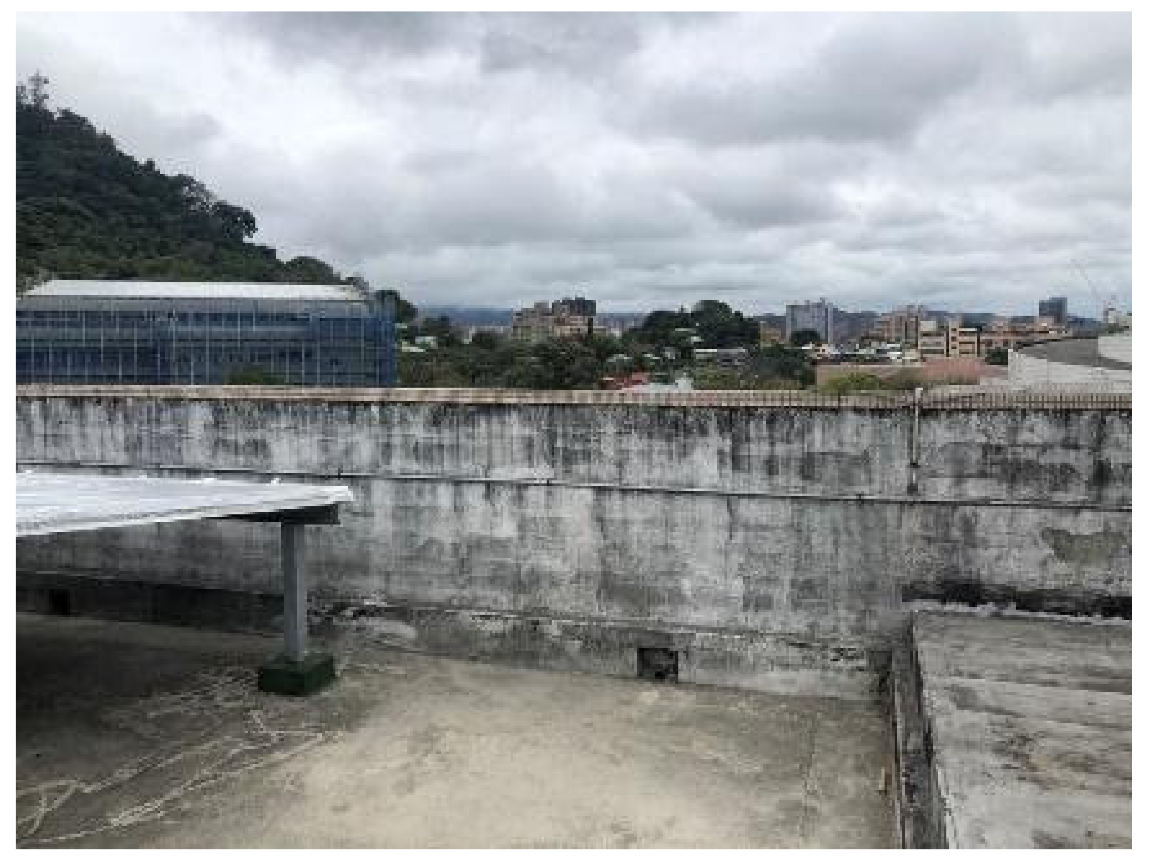
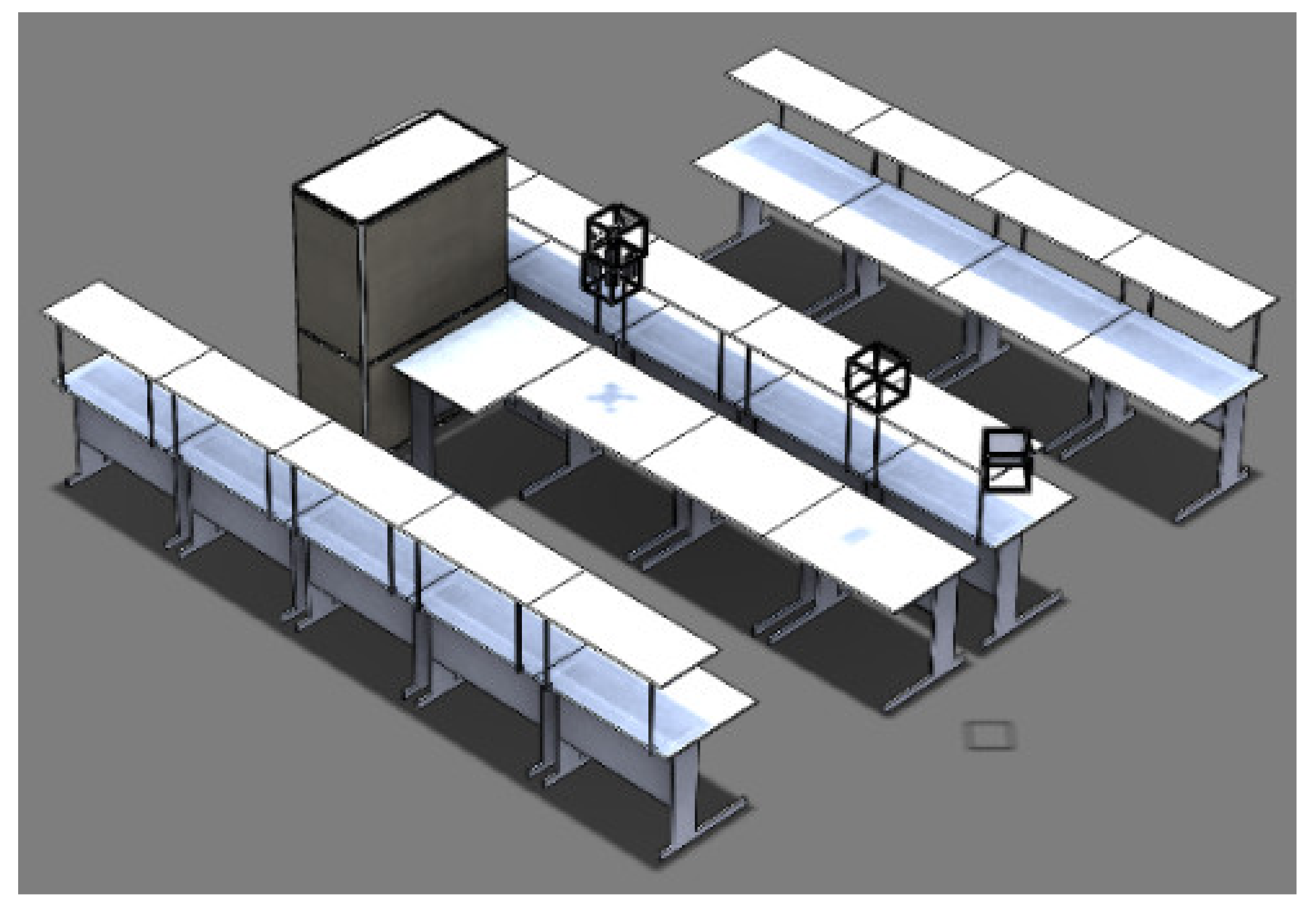
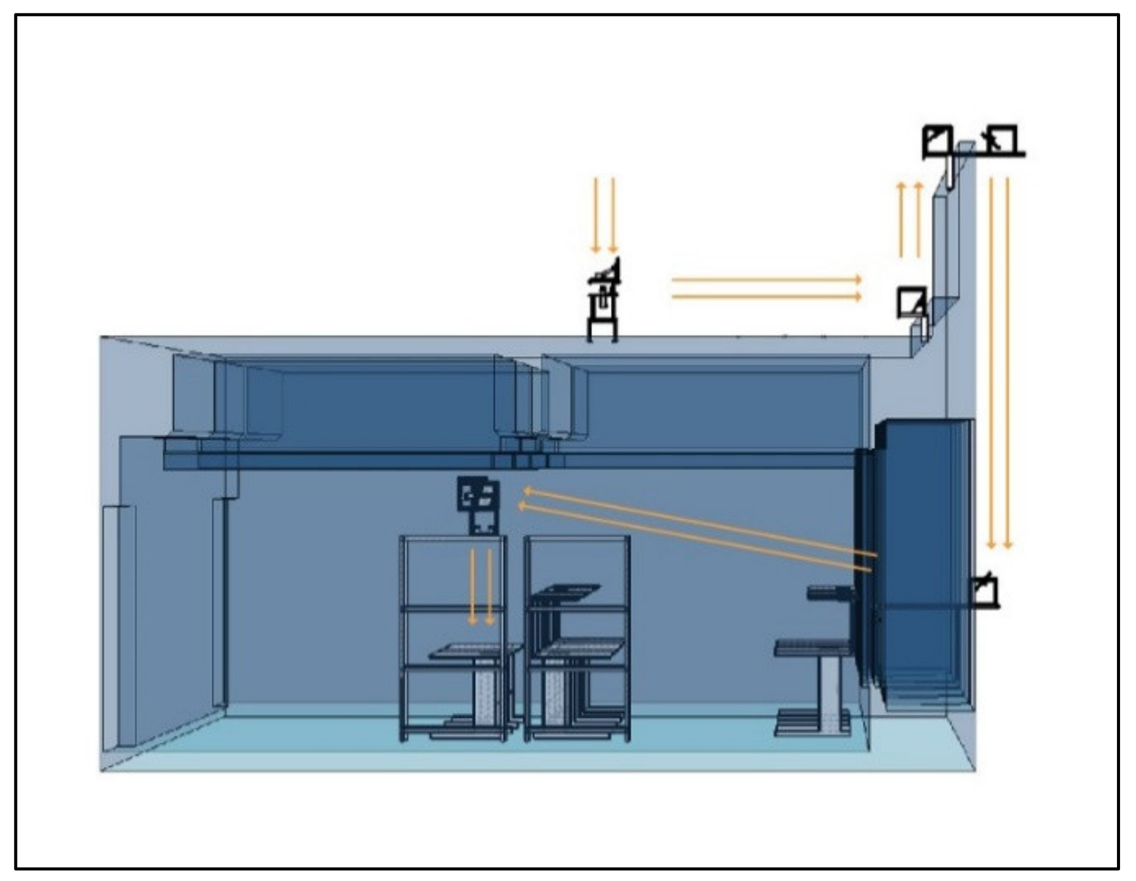
2.1. Field and Optical Path Planning

In planning the light path, the site selected for this work was the rooftop of the 2nd Teaching Building of the National Taiwan University of Science and Technology (NTUST; latitude: 25.0118° N, longitude: 121.5410° E) as the sunlight collection position, as shown in Figure 4. Figure 5 illustrates the indoor office space, which served as the target plane. Modeling software was used to build the field space to select the light path for detailed measurement and module efficiency evaluation. This helped us to select the least difficult construction method. We studied a site plan in Taipei to find a suitable location for the collector, so that it would not be shadowed by any obstructions and a light path with a minimum number of required reflections that would cause transport losses. A light path with great losses, due to multiple turns and excessively long distances, was not chosen. According to the analysis in SolidWorks, the best route was to pass through the outer wall and introduce sunlight from the window. The portable and adjustable system shown in Figure 6, with an optical path around 15   m , comprised five reflection points.
According to ISO 8995–Lighting of indoor workplaces, issued by CIE (International Commission on Illumination), the illuminance of the working area in an office should be greater than 200 lux. Figure 7a,b shows the element size simulation diagram and the light path simulation diagram, respectively. The target plane was set to be 0.9 m × 0.6 m. For reducing the cost and loss, we sought to minimize the coupling and reflecting points between the elements as much as possible.

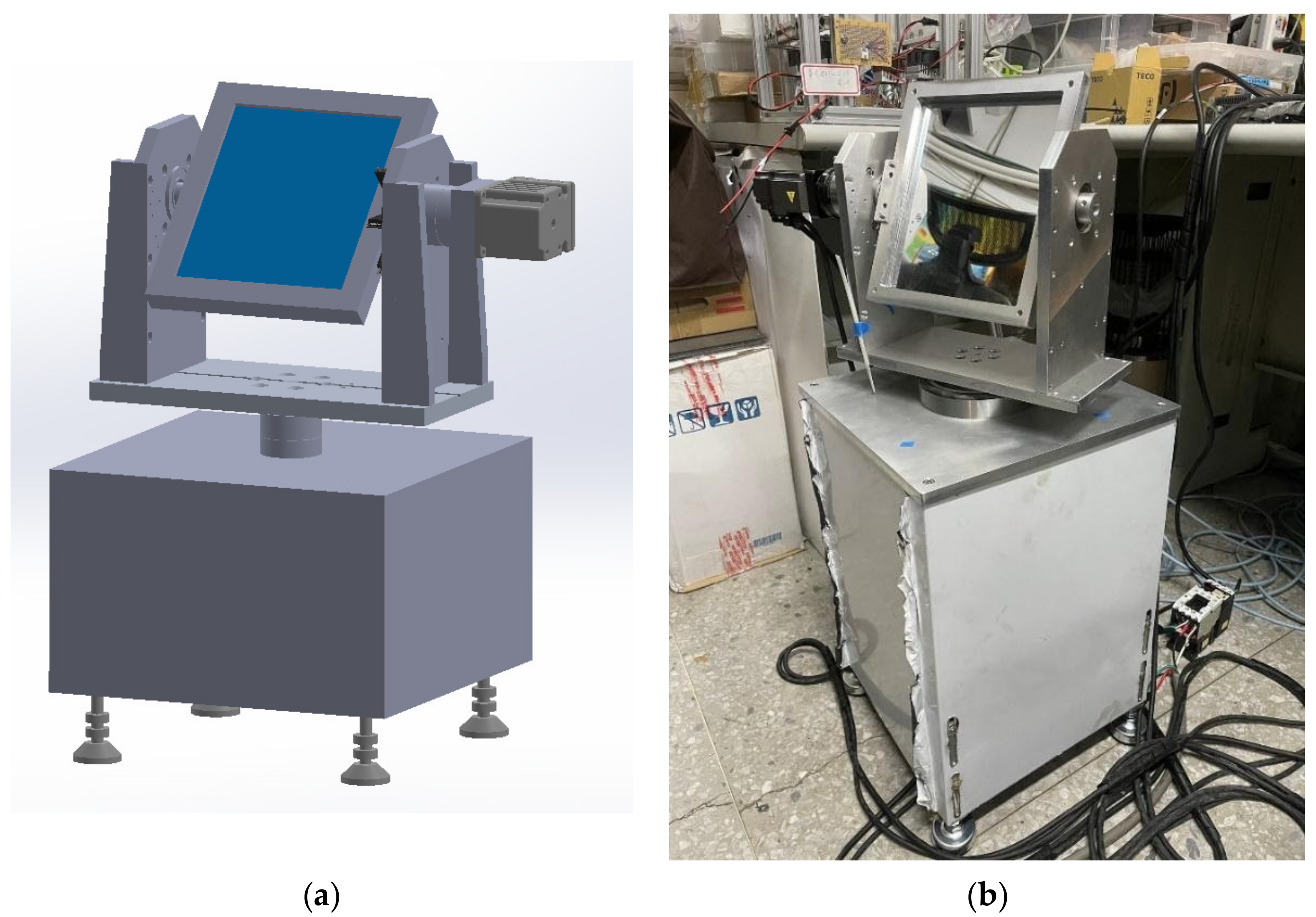
2.2. Mechanical Design

The mechanism design focused on the module support, the degree of protection provided, and the portability. The size and weight of the module affected the portability and difficulty of installation. Therefore, after considering the portability and the cost of optical components, the module size was set at 0.3 m × 0.3 m, and an aluminum extrusion was used as the outer frame, with steel brackets to support the lens or sliding rails. The light cubes were fixed in the field using steel as the support material, and a predrilled wall was used as the fixture. This ensured that the fixed positions of the light cubes and the system were not significantly affected by the wind. Installing and positioning the light cubes involved wall punching, so the locations of each light cube matched the hole position. Figure 8a–d compares the actual object and the simulation of the light cubes. In addition, the heliostat module also used the light cube structure, with an adjustable height.
Based on the light cube infrastructure, the design of the heliostat light cube included a height adjustment and control system. The plan directly impacted the collection and transport performance of the heliostat. During the development process, if a collector with a high sunlight compression ratio was used, the coupling effect and the ratio between the guided light and the entrance light were critical. Furthermore, the material options also affected the manufacturing performance. Using wood with an aluminum-extruded base caused deviation, due to the module being overweight and a lack of structural strength. The heavy system meant that the motor was unable to achieve the deceleration effect, causing it to jitter. The mechanism also bent during repeated handling, forming a permanent deviation. Therefore, in the mechanism design, we removed the unstable factors from the coupling system and used CNC-machined stainless steel as the support material. The original predetermined size of 0.3 m × 0.3 m was equipped with a dual-axis motor and a dual-axis reducer in order to amplify the torque and increase the deceleration effect. The dual-axis system was fixed in the axis center of bearings. The whole mechanism adopted a portable and adjustable design to minimize the effect of the slightly uneven ground in the field. The simulation figure and the prototype module built with stainless steel are shown in Figure 9a,b.

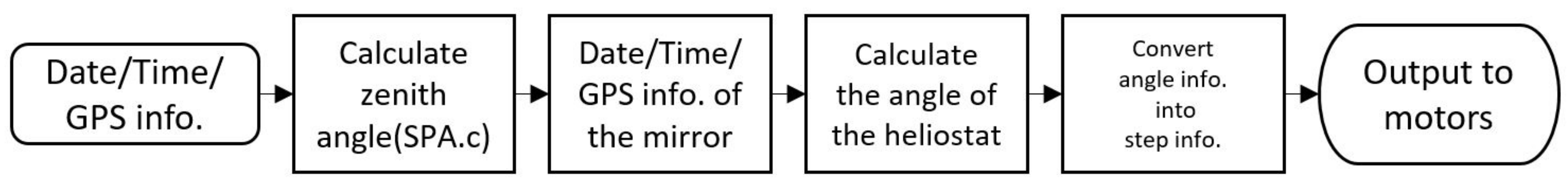
2.3. Control and Communication Design

The model control system for the tracking algorithm of the heliostat was mainly responsible for developing the light cube system’s circuit, firmware, and software. Our primary task for this system was the development of the motor control and the sun-tracking algorithm of the heliostat system. The purpose of the sun-tracking algorithm was to provide sunlight to the room more stably. Therefore, the algorithm calculated the sun’s position first and then calculated the normal vector of the heliostat system by combining the position information of the heliostat system and the next light cube. The optimized NREL’s SPA algorithm [24] was used to calculate the data of the sun’s position in this experiment. The magnetic declination angle ( δ ) for the current day of the year ( n ) was calculated as Equation (1):
δ = 23.45 ° sin 360 284 + n 365 .
The degree was 23.45° between the earth’s equator and the ecliptic. The hour angle H was calculated by the hours of the day with 15° per hour. Then, the zenith angle Z was calculated from the sun’s declination δ, the zenith’s position, the latitude of the target position φ, and the hour angle H, as shown in Equation (2):
cos Z = cos 90 ° cos 90 ° δ + sin 90 ° cos H .
Vincenty’s formulae [25] are a widely used method in geographic surveying, based on the GPS of two points (in latitude and longitude) to calculate the included angle. The zenith’s angle Z and the GPS information were used to calculate the included angle θ between the sun and the normal vector of the heliostat. The angle corresponding to the sunshine time was obtained from Equation (3):
θ = 0.5 cos 1 sin γ × sin β + cos γ × sin ζ × cos β × sin α         + cos γ × cos ζ × cos α × cos β ,
where α is the sun’s azimuth, β is the sun’s elevation, ζ is the target’s azimuth, and γ is the target’s elevation for heliostats, as shown in Figure 10 [26]. The target was the following flat mirror. According to the normal vector of the heliostat, the pitch angle ME and azimuth angle MA can be calculated using Equations (4) and (5) [26]:
M E = sin 1 sin γ + sin β 2 × cos θ ,
M A = sin 1 cos γ × sin ζ + sin β × sin α 2 × cos θ × cos M E .
Therefore, the heliostat system used the GPS information of the flat mirror and the heliostat to calculate the pitch angle and the azimuth angle of the system’s motor by entering the date and the time through NREL’s SPA algorithm, as shown in Figure 10 [24]. Then, using the STM32F407 MCU by I2C, the two angles were converted to move steps for the motors, as illustrated in the flow chart in Figure 11. The design of the two-axis motor system took into consideration both the budget and demands. First, the MR-J3 10A and MR-J4 40A from Mitsubishi were used as servo motors, with APEX AE070 reducer motors to amplify the torque and increase the accuracy by 1:10. Second, HF-KP13J and HG-KR43J from Mitsubishi were used as servo motor controllers, using MR Configurator2 as the motor control software. We set the pitch angle and the azimuth angle accuracy to 36,000 steps. After passing through the magnification of the reducer, 360,000 steps were achieved, meaning the steps of the pitch angle and the azimuth angle reached a sun-tracking accuracy of 0.001°.

3. Optical Module Design and Manufacturing Planning

According to the light path, Figure 12a,b indicates that the design, using a flat mirror as a reflector, restricted and tilted the illuminated area with respect to the incident angle and the size of the mirror. This resulted in an insufficient illuminated area of approximately 0.12 m2 and a poor uniformity. Therefore, a freeform reflector was chosen as an alternate solution to the flat mirror in order to resolve this problem.
The incident light, the freeform reflector, and the target desktop are shown in Figure 13a. First, the three-dimensional coordinate system of the reflector was defined. Then, the distance between the illuminated surface and the freeform mirror was measured in order to determine the size and position of the illuminated surface using Equation (6), as shown in Figure 12b:
y min y max E incident y · y · dy = y min y max E target y · y · dy ,
where y stands for the prescribed coordinate of the incident area, and y stands for the target coordinate of the emitted area. Third, the reflector area and the target region were divided into an equal number of pieces. The energy on one part of the reflector was reflected onto one part of the desktop. The total powers on the mirror and target surface were assumed to be equal. As shown in Figure 13c, the freeform reflector was divided into a / b equal parts along the x / y axes. The values of a / b depended on the precision of the freeform surface, and the prescribed amount of the incident light was evenly distributed onto the desktop. As shown in Figure 13d, the bifocal characteristics of ellipses were utilized to reflect the sunlight into the desired position accurately. The faceted surfaces were generated from the ellipse. Then, the apertures were set to eliminate part of the ellipse in order to form the freeform surface facets with the plane coordinates defined in the first step, as shown in Figure 13e. The illuminated surface area was successfully increased in the initial design, with the parallel light ignoring the solar spread angle, thus reducing the design difficulty. Meanwhile, for the freeform reflector designed through this processes to fit into the light cube module, the facet formed was swept by the modeling software and merged with the backboard, as shown in Figure 13f. Figure 13 demonstrates the simulation result before the system was regressed.

3.1. Deformation Correction and Illuminance Regression

When the light was transmitted through several flat mirrors, each rotation’s projection caused some energy loss and some shape deformation, as shown in Figure 14. In the process of the freeform design, the rectangular target plane, as shown in Figure 15a, caused the shape of the illuminated area to be tilted and become asymmetric, as the incident beam was nonrectangular, as shown in Figure 15b. Therefore, the second design of the freeform surface used an asymmetrically illuminated distribution to correct this problem. First, the sunlight simulation results on the target plane, as shown in Figure 16, were fed back into MATLAB. Then, the target plane was cut into b equal parts along the y-axis, and the integral results were obtained, as shown in Figure 17. Regressions were performed to correct the shape of the light spot and the form of energy distribution in order to achieve a uniformly illuminated area. Figure 15c shows the asymmetric target plane, and the corrected illuminated area is shown in Figure 15d.

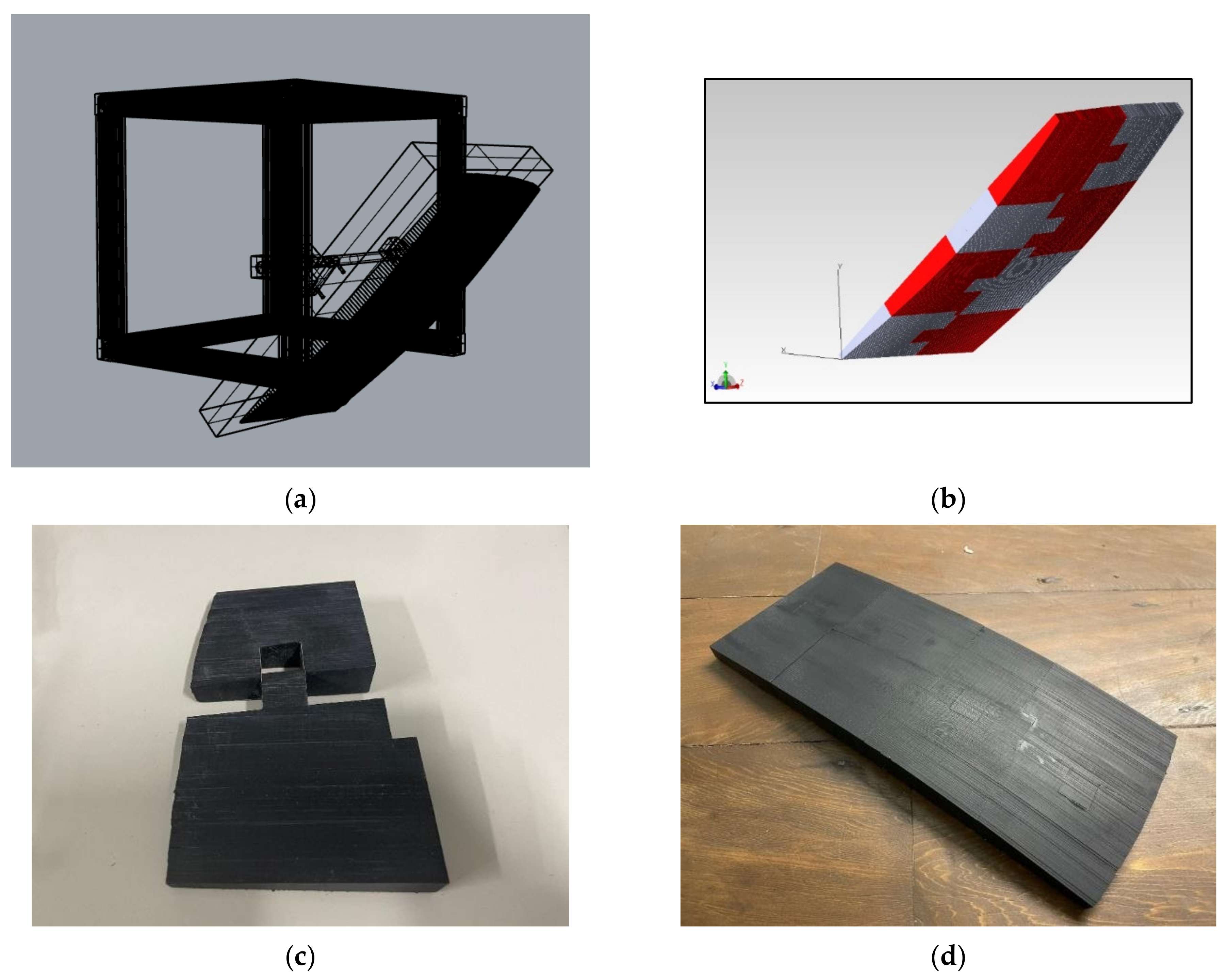
3.2. Manufacturing and Installation

The reflector module combined the designed freeform component with an acrylic backboard, as shown in Figure 18a, replacing the original flat mirror mechanism. Although the fabrication of a freeform reflector required high accuracy, the original freeform reflector was cut into eight pieces for manufacturing, as shown in Figure 18b, in order to meet the limitations of consumer 3D printing machines. Light-curing 3D printing was used for printing, and the finished products are shown in Figure 18c,d.
Vacuum plating consisted of a physical vapor deposition on a surface with a metal material. The light-curing material was liquid composite resin, which did not meet the reflection expectation of this research. Therefore, the parts of the freeform reflector were glued and then coated with a highly reflective aluminum layer through vacuum plating. We used two different kinds of glue to ensure the adhesive’s firmness and temperature resistance. The finished product is shown in Figure 19.

4. Simulation and Measurement Results
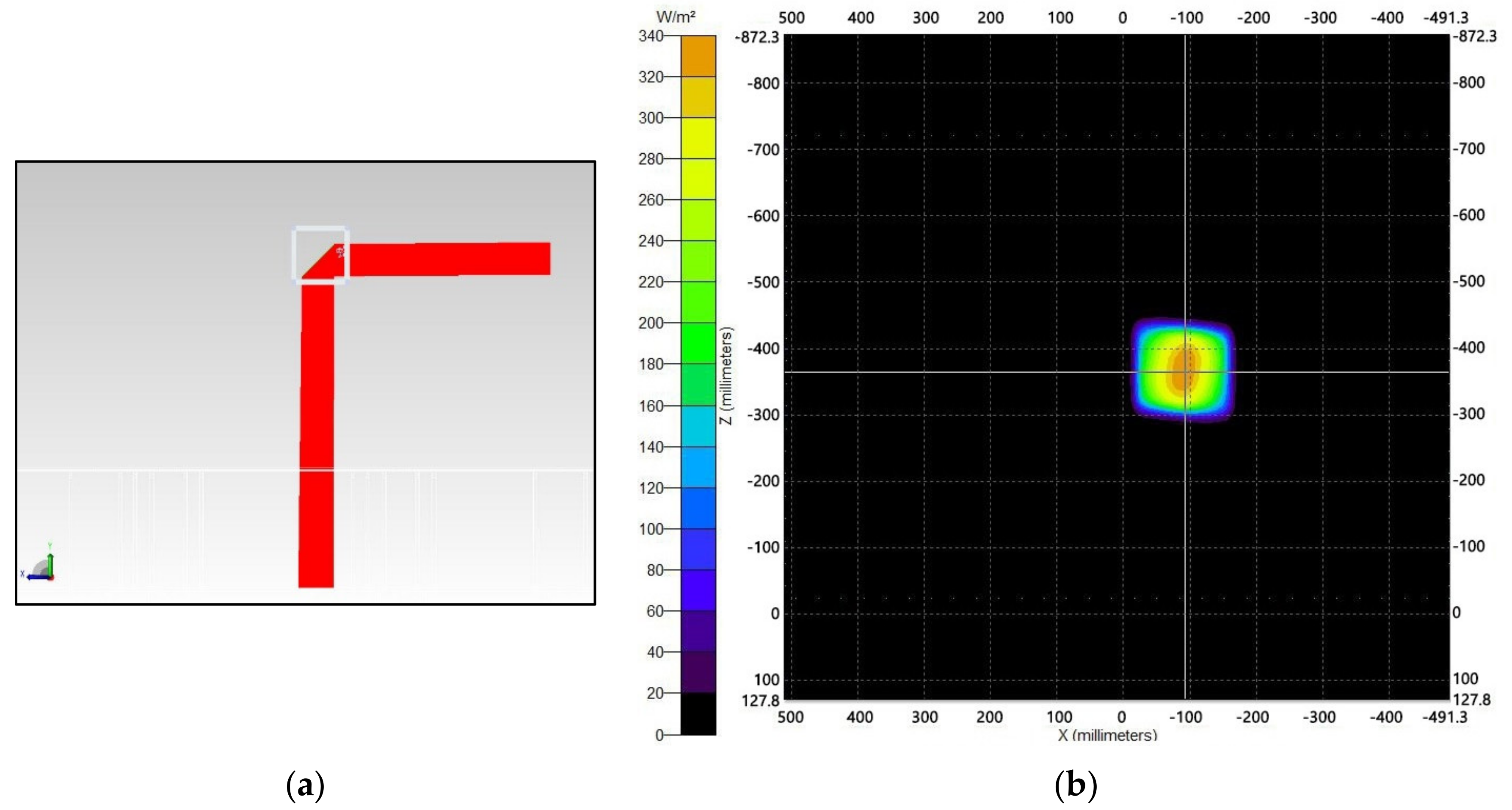
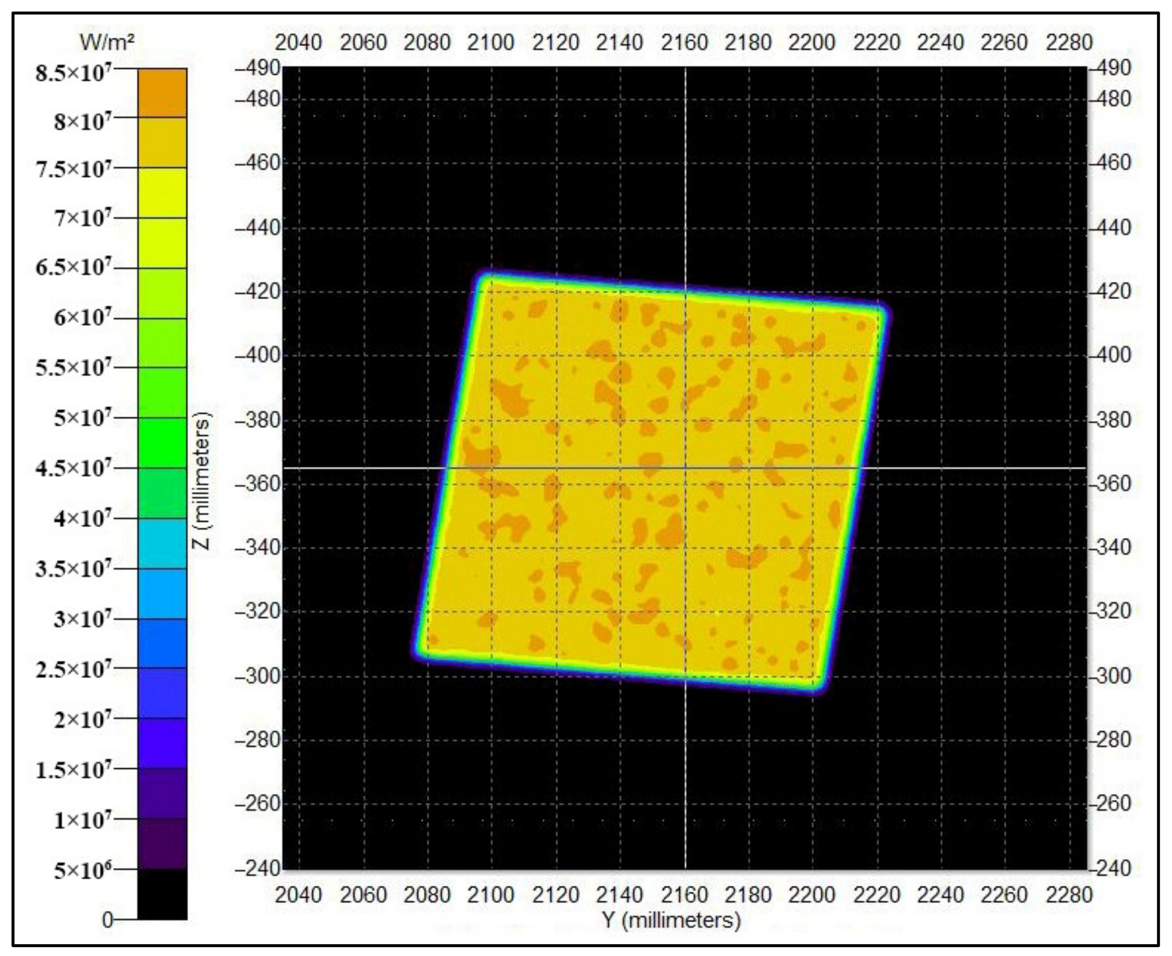
4.1. Simulation

This section describes the simulated and measured results of the system. Figure 20a,b shows the system’s optical path from the heliostat to the desktop. The illumination map of the desktop was used to compare whether the reflector design was effective in correcting for the deformation. Figure 21a shows that the initial design had a clear cut-off, but the projection was distorted due to the rotation of the flat mirror. Although the efficiency was considered in the plan, the uniformity was not expected to form the shape of the illuminated area. Therefore, the steps of the optical design corrected the deformation. The nonuniform energy distribution could be fixed through the polynomial regression shown in Figure 21b,c. The nine-point measurement method stipulated in the indoor lighting secification (CNS 14335) was applied to measure the uniformity of the illuminated area. The distance to the edge of the bright region was marked as 10% and the interval was 40%, as shown in Figure 20c.
The minimum illumination/average illumination calculations were used as a uniformity measurement method, as shown in Equation (7):
Uniformity = Illuminance min Illuminance avg . .
The uniformity values were 0.41 before the polynomial regression optimization and 0.62 after the optimization. After regression, the mirror accurately utilized most of the incident sunlight, as shown in Equation (8):
Reflector   efficiency = Luminous   flux in   target Luminous   flux in   freeform .
As a result, the reflector efficiency was improved from 98% to more than 99%. The system efficiency from the heliostat to the target plane was determined by Equation (9):
System   efficiency = Luminous   flux in   target Luminous   flux in   heliostat .
The system efficiency from the heliostat to the target plane was also increased from 36% to 39%.

4.2. Measurement

The whole system was built in the 2nd Teaching Building of NTUST. The verification time for the fabrication results was from 12:20 to 13:00 on 30 April 2021. According to the location and the season, the sunshine duration was 13 h and 5 min. Each measurement was completed within 4 min, as the incident angle of sunlight took about 4.6 min to change 1°. Each of the nine indoor and nine outdoor points was included, and Table 1 shows the average of 10 measurements. The results are shown in Figure 22 and Figure 23, comparing the outdoor and indoor illuminances.
After the assembly of the eight freeform reflector elements, some minor errors inevitably appeared at the joints. The most significant difference between the practical and simulated results was calibration. Especially for the high-precision design of the freeform component, their positions and rotations in the field affected the final efficiency. Figure 24 shows the illuminated area when using a flat mirror and freeform components. With the latter, the lighting zone was increased, and the deformation caused by rotation was corrected. However, the corrected uniformity of the illuminated area was slightly different from the simulated result. The illuminance on the target plane was about 10,000 lux, the outdoor illuminance was about 107,000 lux, and the uniformity was 0.28, as shown in Table 2. The color temperature changed from 5600 K outdoor to 5100 K indoor, with the loss caused by short-wavelength light loss through the mirrors. It can be noted that the desktop illuminated area was not uniform and the cut-off line was not apparent. In future research, we intend to analyze the tolerance of freeform reflectors, use higher-precision manufacturers, choose more robust materials and increase the smoothness of coating to make the cut-off line more obvious and maintain high efficiency.
In addition to the illuminance, whether the circadian stimulus (CS) value can be achieved or exceeded is also believed to be an essential indicator [27]. Compared with modern artificial lighting, daylight can provide a higher CS value and help the human body during daytime work. Therefore, it is recommended that the CS value should be higher than 0.35. After collecting the spectrum at each measurement point, as shown in Figure 25a, the yellow curve is the spectrum under the test environment, and the indigo curve is the corresponding light intensity of the CS with the CS values of the nine points determined, as illustrated in Figure 25b. The maximum CS value was 0.689, the minimum value was 0.586, and the values were between two standard deviations. Therefore, according to the results, the recommended value for high stimulation was met at each point.

5. Discussion and Conclusions

This article provides a method for designing a modular natural-light lighting system under a limited budget, through the development of a new auxiliary lighting system that maintains light collection efficiency through the use of a dynamic sun-tracing method. A simple diagram shown in Figure 2 provides a easy process to design the complete system. Although the presented results were still subject to errors and corrections, the freeform reflector module we manufactured using 3D printing was constrained to the module size. Enlarging the size of the single module might increase the cost by a huge amount, so a more efficient way to reduce the error created by the glued process is to find a method to divide the module into fragments with a minimum impact on the system. However, the system proved the feasibility of the concept of modular and easily developed sizeable natural lighting systems in highly adaptable modules. With the regression method and the analysis concept, it is more likely to approach the result we desired.
We believe that this indicates successful implementation and offers an excellent design solution under a limited budget. In the future, the proposed lighting device can complement an LED light-assisting system as an auxiliary system in order to provide sufficient and stable illumination. Precision alignment must also be carried out in a large field. The precise fabrication of freeform reflectors will be taken as the research goal in order to conform to the effect of optical simulation. Furthermore, the modularized design will be improved in future planning, with more functional modules, including light collection, collimating, coupling, beam splitting, color separation, beam convergence, LED assistance, and accumulation modules. Moreover, a Bluetooth mesh will also be considered in order to provide the system with the ability to communicate between modules and to adjust in real time.

Author Contributions

Conceptualization, A.J.-W.W.; data curation, Y.-Y.C., M.-Y.L. and Y.-C.L.; formal analysis, H.-W.C. and Y.-C.L.; funding acquisition, A.J.-W.W. and Y.-Z.L.; investigation, Y.-Y.C.; methodology, Y.-Y.C., W.-C.T., Y.-Z.L. and H.-W.C.; project administration, Y.-Y.C.; resources, C.-H.T., T.-C.H., C.-M.C. and H.-C.C.; software, W.-C.T., C.-H.T. and C.-T.L.; supervision, A.J.-W.W.; validation, M.-Y.L., Y.-Z.L., H.-W.C. and C.-H.T.; visualization, W.-C.T., Y.-C.L. and X.Z.; writing—original draft, M.-Y.L.; writing—review and editing, Y.-Y.C. All authors have read and agreed to the published version of the manuscript.

Funding

This work was supported by the Ministry of Science and Technology under 109-2221-E-011-028-.

Institutional Review Board Statement

Not applicable.

Informed Consent Statement

Not applicable.

Data Availability Statement

Not applicable.

Conflicts of Interest

The authors declare no conflict of interest.

References

  1. Nalley, S.; LaRose, A. Annual Energy Outlook 2020; US Energy Information Administration: Washington, DC, USA, 2019; p. 63.
  2. Gago, E.J.; Muneer, T.; Knez, M.; Köster, H. Natural light controls and guides in buildings. Energy saving for electrical lighting, reduction of cooling load. Renew. Sustain. Energy Rev. 2015, 41, 1–13. [Google Scholar] [CrossRef]
  3. Dunne, A. Some effects of the quality of light on health. J. Orthomol. Med. 2015, 7, 229–323. [Google Scholar]
  4. Gallaway, T.; Olsen, R.N.; Mitchell, D.M. The economics of global light pollution. Ecol. Econ. 2010, 69, 658–665. [Google Scholar] [CrossRef]
  5. Mead, M.N. Benefits of Sunlight: A Bright Spot for Human Health. Environ. Health Perspect. 2008, 116, A160–A167. [Google Scholar] [CrossRef] [PubMed] [Green Version]
  6. Al Horr, Y.; Arif, M.; Kaushik, A.; Mazroei, A.; Katafygiotou, M.; Elsarrag, E. Occupant productivity and office indoor environment quality: A review of the literature. Build. Environ. 2016, 105, 369–389. [Google Scholar] [CrossRef] [Green Version]
  7. Odeh, I.; Hussein, T. Activity Pattern of Urban Adult Students in an Eastern Mediterranean Society. Int. J. Environ. Res. Public Health 2017, 13, 10. [Google Scholar] [CrossRef] [Green Version]
  8. Vu, N.-H.; Shin, S. Cost-effective optical fiber daylighting system using modified compound parabolic concentrators. Sol. Energy 2016, 136, 145–152. [Google Scholar] [CrossRef]
  9. Beccali, M.; Bonomolo, M.; Brano, V.L.; Ciulla, G.; di Dio, V.; Massaro, F.; Favuzza, S. Energy saving and user satisfaction for a new advanced public lighting system. Energy Convers. Manag. Sep. 2019, 195, 943–957. [Google Scholar] [CrossRef]
  10. Sharp, F.; Lindsey, D.; Dols, J.; Coker, J. The use and environmental impact of daylighting. J. Clean. Prod. 2008, 85, 462–471. [Google Scholar] [CrossRef]
  11. Chang, C.-H.; Hsiso, H.-C.; Chang, C.-M.; Wang, C.-Y.; Lin, T.-H.; Chen, Y.-Y.; Lai, Y.-L.; Yen, C.-J.; Chen, K.-Y.; Whang, A.J.-W. Heliostat design for the daylighting system. Appl. Opt. 2014, 53, H165–H169. [Google Scholar] [CrossRef] [PubMed]
  12. Whang, A.J.; Chao, S.-M.; Chou, C.-H.; Lin, C.-M.; Chang, C.-M.; Jhan, K.-C.; Wang, C.-W. Innovative coupler design based on a tapered light pipe with lens. Chin. Opt. Lett. 2013, 11, 122201-122201. [Google Scholar] [CrossRef]
  13. Barbón, A.; Sánchez-Rodríguez, J.; Bayón, L.; Bayón-Cueli, C. Cost estimation relationships of a small scale linear Fresnel reflector. Renew. Energy 2018, 134, 1273–1284. [Google Scholar] [CrossRef]
  14. Pham, T.T.; Vu, N.H.; Shin, S. Daylighting System Based on Novel Design of Linear Fresnel lens. Buildings 2017, 7, 92. [Google Scholar] [CrossRef] [Green Version]
  15. Ullah, I.; Shin, S. Highly concentrated optical fiber-based daylighting systems for multi-floor office buildings. Energy Build. 2014, 72, 246–261. [Google Scholar] [CrossRef]
  16. Lv, Y.; Xia, L.; Li, M.; Wang, L.; Su, Y.; Yan, J. Techno-economic evaluation of an optical fiber based hybrid solar lighting system. Energy Convers. Manag. 2020, 225, 113399. [Google Scholar] [CrossRef]
  17. Tian, M.; Su, Y.; Zheng, H.; Pei, G.; Li, G.; Riffat, S. A review on the recent research progress in the compound parabolic concentrator (CPC) for solar energy applications. Renew. Sustain. Energy Rev. 2017, 82, 1272–1296. [Google Scholar] [CrossRef] [Green Version]
  18. Carli, R.; Dotoli, M. A Dynamic Programming Approach for the Decentralized Control of Energy Retrofit in Large-Scale Street Lighting Systems. IEEE Trans. Autom. Sci. Eng. 2020, 17, 1140–1157. [Google Scholar] [CrossRef]
  19. Kontadakis, A.; Tsangrassoulis, A.; Doulos, L.; Topalis, F. An active sunlight redirection system for daylight enhancement beyond the perimeter zone. Build. Environ. 2017, 113, 267–279. [Google Scholar] [CrossRef]
  20. Donald Prowler and Associates. Sun Control and Shading Devices. In Whole Building Design Guide; National Institute of Building Sciences: Washington, DC, USA, 2016. [Google Scholar]
  21. Babu, S.; Zhou, J.; Wan, M.P.; Lamano, A.S.; Sarvaiya, J.N.; Zhang, Z.; Kumar, D.K.; Gao, C.-P.; Valliappan, S.; Goh, A.; et al. Investigation of an integrated automated blinds and dimmable lighting system for tropical climate in a rotatable testbed facility. Energy Build. 2018, 183, 356–376. [Google Scholar] [CrossRef]
  22. Wagiman, K.R.; Abdullah, M.N.; Hassan, M.Y.; Radzi, N.H.M.; Abu Bakar, A.H.; Kwang, T.C. Lighting system control techniques in commercial buildings: Current trends and future directions. J. Build. Eng. 2020, 31, 101342. [Google Scholar] [CrossRef]
  23. Whang, A.J.-W.; Chen, Y.-Y.; Yang, S.-H.; Pan, P.H.; Chou, K.H.; Lee, Y.C.; Lee, Z.Y.; Chen, C.-A.; Chen, C.-N. Natural light illumination system. Appl. Opt. 2010, 49, 6789–6801. [Google Scholar] [CrossRef] [PubMed]
  24. Reda, I.; Andreas, A. Solar Position Algorithm for Solar Radiation Applications; National Renewable Energy Laboratory: Golden, CO, USA, 2008.
  25. Vincenty, T. Geodetic Inverse Solution between Antipodal Points. In DMAAC Geodetic Survey; Ohio State University: Columbus, OH, USA,, 1975. [Google Scholar] [CrossRef]
  26. Lin, Y.Z.; Fu, Y.T.; Chan, K.C.; Lin, C.M.; Chen, H.C.; Whang, A.J.W. Heliostat for Natural Light Illumination System. In Proceedings of the 2nd International Conference on Electrical Engineering and Computer Science, Taipei City, Taiwan, 28–29 October 2016. [Google Scholar]
  27. Rea, M.; Figueiro, M. Light as a circadian stimulus for architectural lighting. Light. Res. Technol. 2016, 50, 497–510. [Google Scholar] [CrossRef]
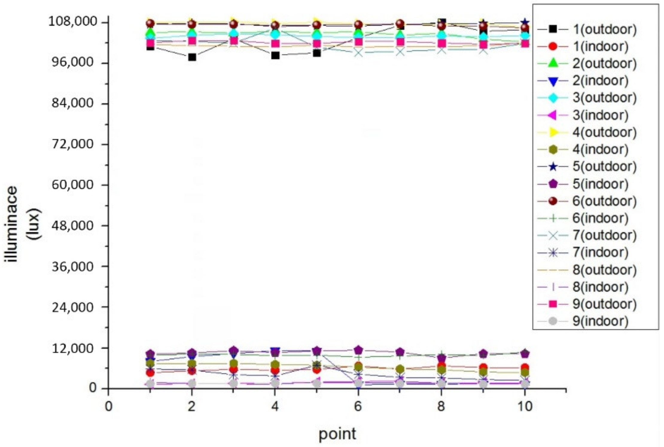
Figure 1. Various modules expected in the future. 1. heliostat; 2. light-collecting module; 3. collimating module; 4. reflecting module; 5. beam-splitting module; 6. coupling module; 7. color separation module; 8. light convergent module; 9. emission module; and 10. accumulation module (solar cell).
Energies 15 00406 g001
Figure 2. System design diagram.
Energies 15 00406 g002
Figure 3. Flow chart of the proposed optical/mechanical design.
Energies 15 00406 g003
Figure 4. The rooftop of the experimental field.
Energies 15 00406 g004
Figure 5. Perspective view of the target desks.
Energies 15 00406 g005
Figure 6. Perspective view of the field.
Energies 15 00406 g006
Figure 7. (a) Element size simulation diagram; and (b) light path simulation diagram.
Energies 15 00406 g007
Figure 8. Perspective views of the light cube in CAD software (a,b) and the actual light cube in situ (c,d).
Energies 15 00406 g008
Figure 9. (a) CAD model of the heliostat module; and (b) heliostat module built with a stainless steel outer frame.
Energies 15 00406 g009
Figure 10. Schematic view of the heliostats, the sun, and the target in the horizon coordinate system.
Energies 15 00406 g010
Figure 11. Flow chart of the sun-tracking algorithm of the heliostat system.
Energies 15 00406 g011
Figure 12. (a) Perspective view of optical path design with a flat mirror as the reflector; and (b) illuminance map of the target plane reflected by a flat mirror.
Energies 15 00406 g012
Figure 13. Optical module design for the following: (a) defining the coordinates of the reflector plane; (b) measuring the size of the target plane and the distance between the reflector and the target plane; (c) determining the number of segments (in (a) and (b), respectively) along the x / y axes; (d) making every facet ellipsoid with the size of the element (schematic sketch; the elements of the facetted reflector had sizes of 3 mm × 3 mm); (e) eliminating the excessive part; and (f) converting freeform surfaces to solids.
Energies 15 00406 g013
Figure 14. Illuminance map of the target plane, according to the freeform reflector design process.
Energies 15 00406 g014
Figure 15. (a) Prescribed symmetric grid-reflected plane to arrange the focal point; (b) asymmetric illuminance map of the target plane; (c) prescribed asymmetric grid-reflected plane; and (d) symmetric illuminance map of the target plane observed using a point light source.
Energies 15 00406 g015aEnergies 15 00406 g015b
Figure 16. Illuminance map of the previous plane of the target plane.
Energies 15 00406 g016
Figure 17. Energy integration results along the y-axis on the illuminated surface.
Energies 15 00406 g017
Figure 18. (a) Module simulation shown in CAD software; (b) freeform reflector divided into eight pieces; (c) parts of the freeform mirror before coating; and (d) glued freeform surface before coating.
Energies 15 00406 g018
Figure 19. (a) Aluminum-coated freeform reflector; (b) mirror glued on an acrylic backboard; and (c) freeform reflector module installed in the field.
Energies 15 00406 g019
Figure 20. (a) Prescribed optical path in the field; (b) side view of the freeform reflector module and the target plane; and (c) prescribed measurement point on the target plane.
Energies 15 00406 g020
Figure 21. Illuminance map of the target plane before any correction (a), with an incident plane shape correction only (b), and with a shape correction and an illuminance regression (c).
Energies 15 00406 g021
Figure 22. Results for the 10 measurements of outdoor and indoor illuminances.
Energies 15 00406 g022
Figure 23. (a) Aluminum outer frame of a light cube installed in the field and; (b) combination of a freeform reflector and an aluminum outer frame.
Energies 15 00406 g023
Figure 24. (a) Illuminated area emitted by a flat mirror; and (b) illuminated area emitted by a freeform reflector.
Energies 15 00406 g024
Figure 25. (a) Circadian stimulus (CS) value corresponding to the wavelength (the yellow curve is the spectrum under the test environment, and the indigo curve is the corresponding light intensity of the CS); and (b) CS values of the nine measured points on the target surfaces.
Energies 15 00406 g025
Table 1. Comparison of outdoor and indoor illuminance measurement results.
PointAverage Outdoor Illuminance
(10 Times; in Lux)
Average Indoor Illuminance
(10 Times; in Lux)
1103,067.35845.2
2104,665.95663.8
3104,079.11704.1
4107,786.06391.3
597,898.010,555.1
6107,345.69940.0
792,571.74197.6
8101,275.51611.5
9102,244.51479.2
Table 2. Uniformity comparison of the simulated and measured results.
TypeUniformity
Simulation (before regression)0.41
Simulation (after regression)0.62
Measurement0.28
Publisher’s Note: MDPI stays neutral with regard to jurisdictional claims in published maps and institutional affiliations.

