Article

Contemporary Atrium Architecture: A Sustainable Approach to the Determination of Smoke Ventilation Criteria in the Event of a Fire

by
Maria Brzezińska
1 and
Dorota Brzezińska
2,*
1
Faculty of Civil Engineering, Architecture and Environmental Engineering, Lodz University of Technology, 116 Zeromskiego Street, 90-924 Lodz, Poland
2
Faculty of Process and Environmental Engineering, Lodz University of Technology, 213 Wolczanska Street, 90-924 Lodz, Poland
*
Author to whom correspondence should be addressed.
Energies 2022, 15(7), 2484; https://doi.org/10.3390/en15072484
Submission received: 8 March 2022 / Revised: 21 March 2022 / Accepted: 24 March 2022 / Published: 28 March 2022
(This article belongs to the Special Issue Sustainability and Wellness for Building Lighting and Ventilation)

Abstract

:
Atria within buildings present an environment which allows smoke to spread around a building in a fire situation. This could create dangerous conditions for the evacuation of people. Smoke control ventilation systems in atria work in the case of a fire, keeping evacuation routes available for people. They play a significant role in sustainable, holistic building fire strategies, and are most often designed following prescriptive requirements. However, contemporary, complex atria with additional architectural elements—such as transversal balconies—may not meet the standard approach, and require individual, performance-based research. This article proves a thesis that the atrium’s architecture can impact the effectiveness of smoke control systems, and suggests how to verify them based on CFD simulations. In the presented example, the authors suggest an improvement of people’s safety in a fire scenario by extending the preliminary smoke control system parameters, or by providing smoke curtains at additional levels of the atrium.

1. Introduction

An atrium was historically a central room in the residential houses of ancient Rome, around which living rooms were arranged. It often consisted of a compluvium (a hole in the roof) and an impluvium (a rainwater tank) below it. Today, the atrium is a large room, often with glass walls and a glass roof, created especially in the middle of a large shop or office building. The primary targets of fire safety engineering is to ensure people’s safety in the building, and to determine the most effective strategy to limit the consequences of a fire. Beyond human life, assets, business interests, and the environment have to be strongly protected. A significant role in this field is played by smoke control systems, which can minimize both damages to materials and the fire’s impact on the environment [1]. Chow and Chow define sustainability as the ability to be maintained at a steady level without exhausting natural resources or causing severe ecological damage [2]. Damage control is also a primary goal of fire safety and smoke control systems, and it could be assumed that the objectives of both the sustainability and fire safety subjects are aligned [3]. Modern architectural techniques allow atria to be an integral part of large buildings, designed for the provision of a visually and spatially external environment in enclosures. Very often, such concepts appear in green and sustainable buildings. The most popular examples can be found in covered shopping malls, office buildings, museums, and concert halls [4].
Atria can be classified according to the architecture of the object, as presented in the book ‘Design Methodologies for Smoke and Heat Exhaust Ventilation’ [5]. There are four basic types of atria:
  • Sterile atria, which are fully separated from the rest of the building, with the use of fire resistance and smoke-proof partitions;
  • Closed atria, which are also separated from the rest of the building, while the partitions used for separation do not have to have a fire resistance class or be smoke-tight;
  • Partially open atria, where only higher floors remain, which—like in closed atria—have not been separated by smoke-tight or fire-resistant partitions;
  • Open atria, where all floors are open on the atrium space.

1.1. Smoke Control Systems of Atria

Smoke control systems in the atrium space play a significant role in sustainable, holistic building fire strategies [3]. They are based on the smoke exhaust and fresh air supply elements [6,7].
Atrium fire safety design is very challenging, especially in the field of smoke control systems [8]. In general, the smoke exhaust should be located in the upper part of the atrium, and for the smoke exhaust to be effective, there should also be an inflow of fresh air in the lower part of the space. In order to protect the evacuation routes in atria against smoke, natural or mechanical smoke extraction systems are used [9]. This is required by Polish regulations [9], which state that “in the covered pedestrian route (passage) adjacent to commercial and service premises, and in the covered internal courtyard, technical and construction solutions should be applied to prevent smoke on the escape routes” (§ 247 Act 2 [10]).
The design of smoke control systems in atria based on a model of a free smoke column was created by Heskestad [11]. In this model, the generated volume of smoke is determined by the mechanism of the convective air inflow to the smoke column (Figure 1). The authors visualized the theoretical assumptions in a smoke test based on smoke creation and propagation. The smoke in the test was created in the smoke generator, and was heated by a small fire source. The most important parameter is the height of the smoke movement from the fire source to the smoke reservoir. This depends on the atrium’s type and its height. Generally, it is assumed that the lower boundary of the smoke layer should be at least 1.8 m from the top floor opening onto the atrium’s space [12].
The actual literature in the field of atria smoke control systems concentrates on their technical aspects [13], modern ventilation solutions like special vent locations or capacity [4,14], or CFD software’s validation [15,16]. In general, the aspect of the atrium’s internal design on the smoke control system’s effectiveness has not been investigated.
The contemporary architectural designs of atria are often very impressive but also complicated. It is known that the smoke exhaust and make-up air configurations are very significant influences on the smoke distribution and the smoke control system’s effectiveness is [14]. However, additional complications can appear as a consequence of unusual atrium architectural elements. Apart from the atrium types described above, we can also distinguish simple atria, where the internal space is free of additional components (Figure 2), or complex atria, where transversal balconies, beams, or other additional architectural features are implemented (Figure 3). The obstacles created in the atrium space could be more or less influenced by the smoke dispersion. Figure 3a presents an atrium with many beams, which would probably be almost neutral for the smoke flow, while Figure 3b presents wide balconies running across the atrium, which could cause a great diffusion of smoke.
This article suggests that the atrium’s architecture, especially the large additional internal elements found in the complex atrium, can affect the effectiveness of smoke control systems. The reason is that architectural details, such as balconies, can influence the amount of smoke generated, multiplying the convective smoke plume (Figure 4). Consequently, the actual volume of smoke could be greater than that calculated, and the smoke control system could not be effective enough.

1.2. CFD Simulations in the Smoke Control Systems’ Design

CFD (Computational Fluid Dynamics) computer simulations are increasingly used to verify the effectiveness of smoke control systems as a confirmation of preliminary hand calculations. Thanks to CFD technology, it is possible to solve complex equations that describe the flow of fluids in a three-dimensional system and take into account the passage of time.
These methods are already widely validated, and their examples are described in the literature [16,17]. The atria, as especially difficult objects of evaluation for people’s safety in fires, are one of the most popular subjects for CFD analysis [13]. The smoke layer interface height can be obtained by simulation using a design fire with a constant or growing heat release rate (HRR).
The program most often chosen by users is Fire Dynamics Simulator (FDS), which currently has several thousand users, and in this field is the best-verified around of all of the simulation programs [13,17,18,19]. Due to the above, the FDS was chosen for the simulations presented in this article. The software uses a large eddy simulation (LES) turbulence model, which can be used to predict the upward flame and smoke spreads, as well as ventilation air flows [20,21,22].
This article demonstrates how to make hand calculations of the atrium smoke control system, and how to use CFD simulations for its verification. Finally, some conclusions about the smoke control system’s effectiveness and the methods of its improvement in complex atria are formulated.
The flow chart in Figure 5 presents subsequent steps of the analyses based on an example complex atrium space located in the LabFactor Building, at Lodz University of Technology in Poland.
The intention of this article is to demonstrate that the atrium architecture can impact the effectiveness of smoke control systems, and it suggests how to verify them based on CFD simulations. The presented analysis visualizes the problem and gives suggestions on how the designers could solve it. The actual research was realised at the qualitative level, rather than the quantitative level. Further works will concentrate on the quantitative approach of the standard hand calculation methods and their adaptation to the requirements of modern architecture.

2. The Exemplar Atrium Analysis

This article is based on a complex atrium in the LabFactor building example, located at the Lodz University of Technology in Poland (Figure 6). The proposed research is based on a fire source location related to the balcony running through the atrium space. The presented preliminary hand calculations of the designed smoke control system were verified by CFD simulations, looking for a confirmation of the thesis of the sensitivity of the smoke exhaust system to additional architectural elements.

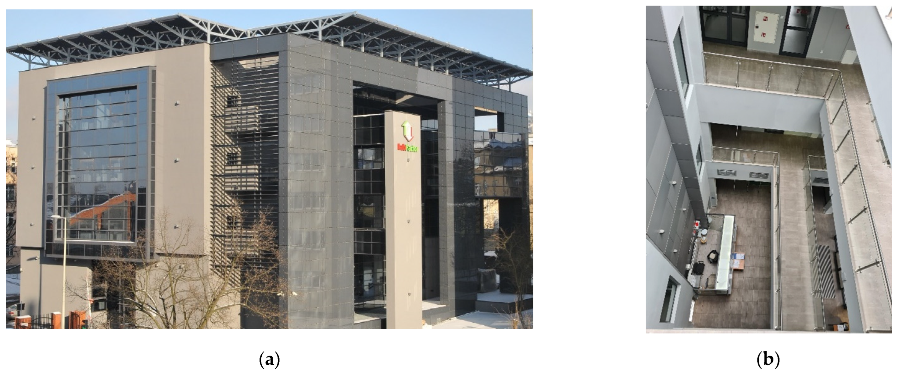
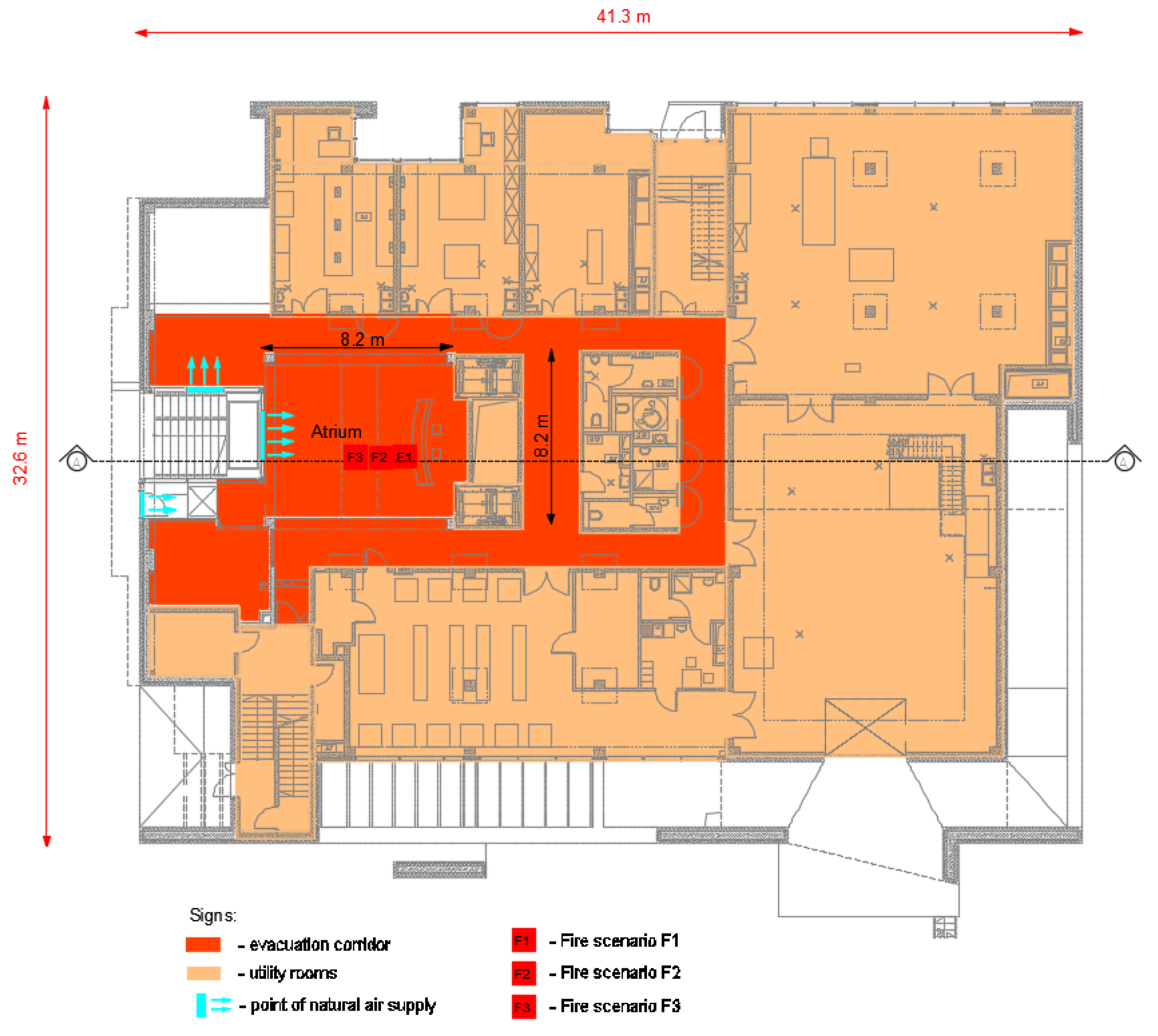
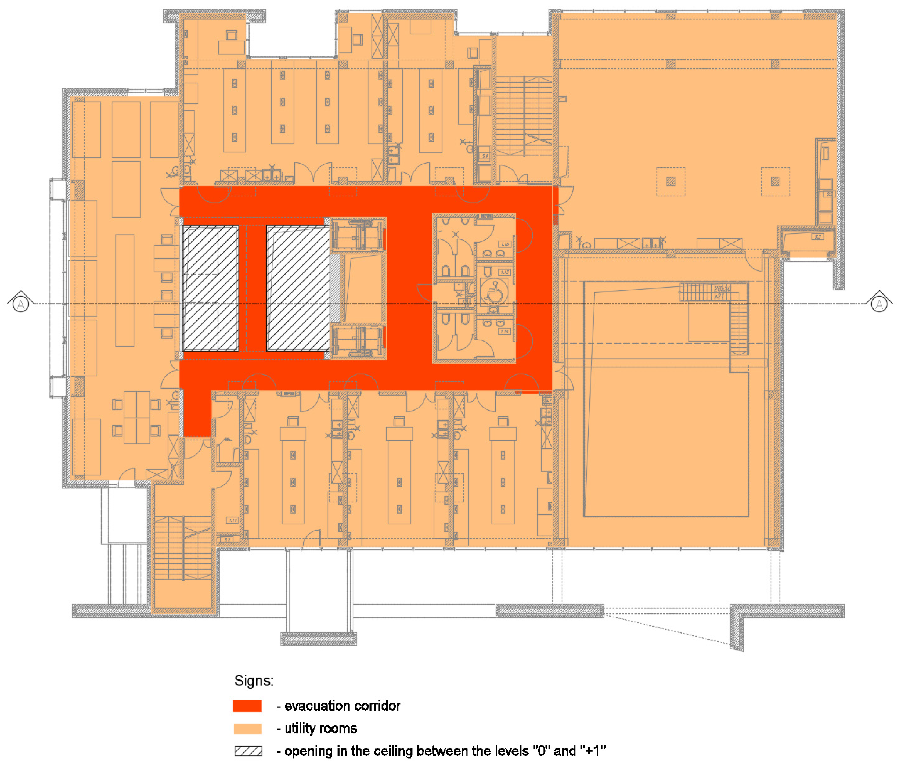
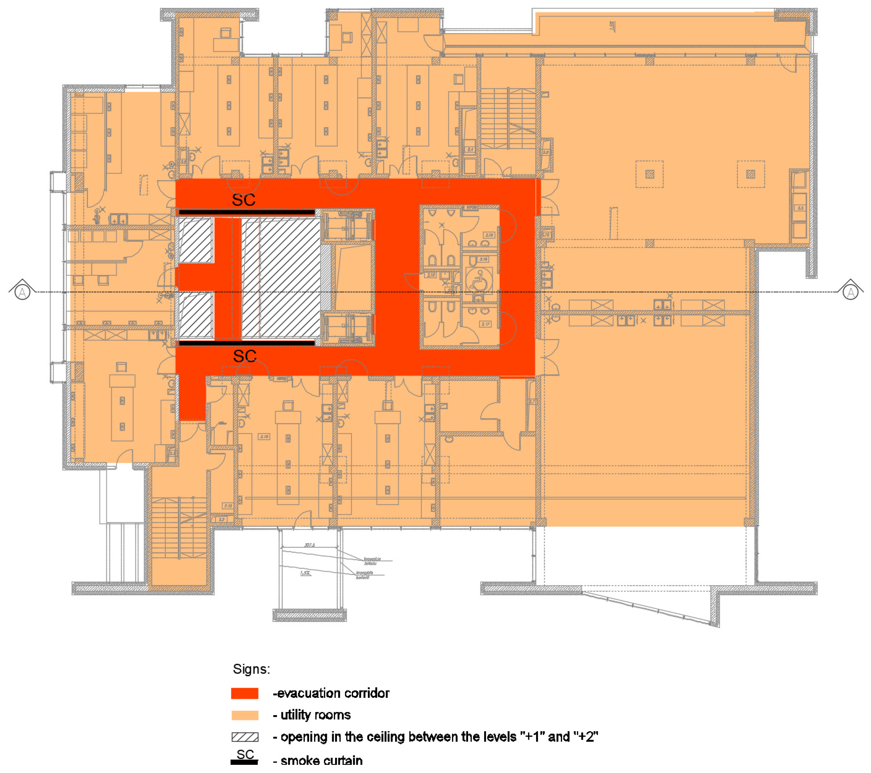
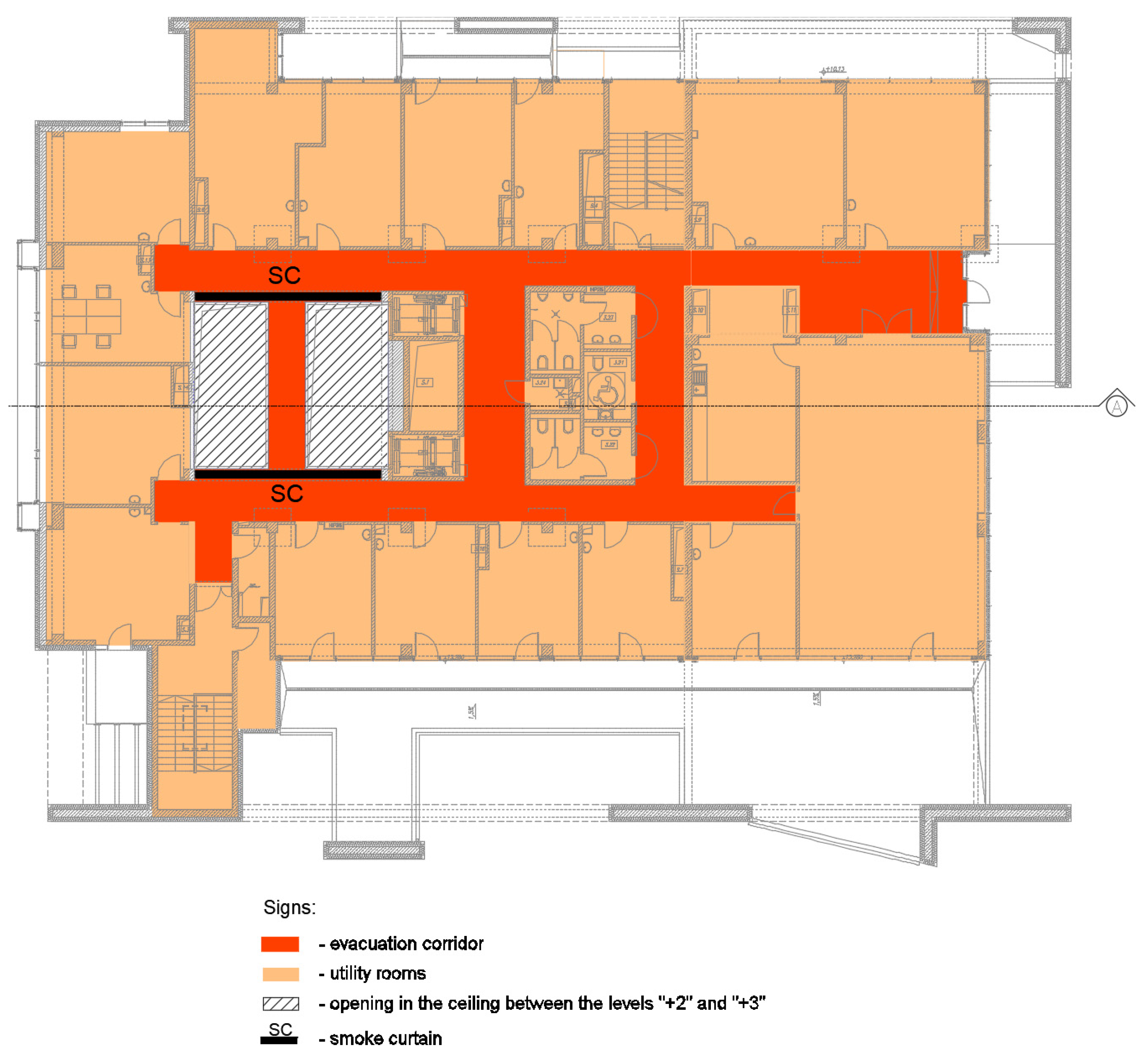
2.1. Atrium in the LabFactor Building

The atrium in the LabFactor building of the Lodz University of Technology covers four levels. On each floor, both sides of the atrium are connected by balconies (Figure 7, Figure 8, Figure 9, Figure 10 and Figure 11). The atrium is partially open, and the two highest floors are closed by smoke curtains (Figure 8, Figure 9, Figure 10 and Figure 11). The main dimensions of the building and the atrium are shown in Figure 7. The total height of the atrium is 20.3 m, and each level’s heights are given in Figure 11.
All of the doors to the rooms adjacent to the atrium are equipped with door self-closers, which significantly reduce the possibility of smoke entering the atrium from them in the case of a room fire. A reception desk on the ground floor of the atrium could be a possible source of the fire, which is assumed as the worst-case fire scenario.

2.2. The Atrium Smoke Control System

The atrium has a gravitational smoke control system. There are smoke vents in the roof skylight, and an air supply window and doors located on the ground floor of the building. The total effective area of the air supply openings is 10 m2.
The theoretical calculation of the smoke control system’s parameters was based on the British Standard [23] requirements. The total heat flux of the fire was assumed to be 1 MW, which represents a standard office desk fire [24]. This is based on the assumptions presented below:
Ce—air entrainment coefficient = 0.19 kg/sm5/2,
P—fire perimeter = 6 m,
Y—smoke column rise height = 7.4 m,
Q—convective heat flux = 700 kW (70% of the total heat flux of 1 MW),
c—specific heat of the air = 1.01 kJ/kg K,
ρ—air density at the ambient temperature = 1.2 kg/m3,
To—ambient air temperature = 293.15 K,
g—gravity coefficient = 9.81 m/s2,
H—total height of the atrium = 20.3 m,
v—maximum speed of the supply airflow ≤ 2.5 m/s
Ai—total effective area of the air supply openings = 10 m2,
Ci—coefficient of discharge = 1.0.
Based on the assumptions above, it was possible to calculate the required smoke vents’ effective area based on the following equations from the BS standard [8].
The first step was to calculate the mass stream of the produced smoke Mf, (Equation (1)).
M f = C e P Y 3 2 = 0.19 6 7.4 3 2 = 23.42 kg s
The next step was to calculate the smoke temperature increase above the ambient temperature (Equation (2)).
θ = Q M f c = 700 23.42 1.01 = 30 K
Finally, the effective smoke vents’ area was estimated (Equation (3)).
A v C v = M f T 2 ρ   2 g d θ T o M f 2 T T o ( A i C i ) 2 = = 23.42 323.15 2 1.2   2 9.81 13 30 293.15 23.42 2 323.15 293.15 ( 10 1.0 ) 2 = 4.23     m 2
The presented calculations for a fire scenario on the atrium floor demonstrated that the smoke control system, equipped with smoke vents of an effective area of AvCv = 4.23 m2, is required to maintain the smoke level at the height of 7.4 m above the floor. This would allow a safe evacuation of people from the atrium.
The calculations were verified by the CFD simulations presented in the next section.

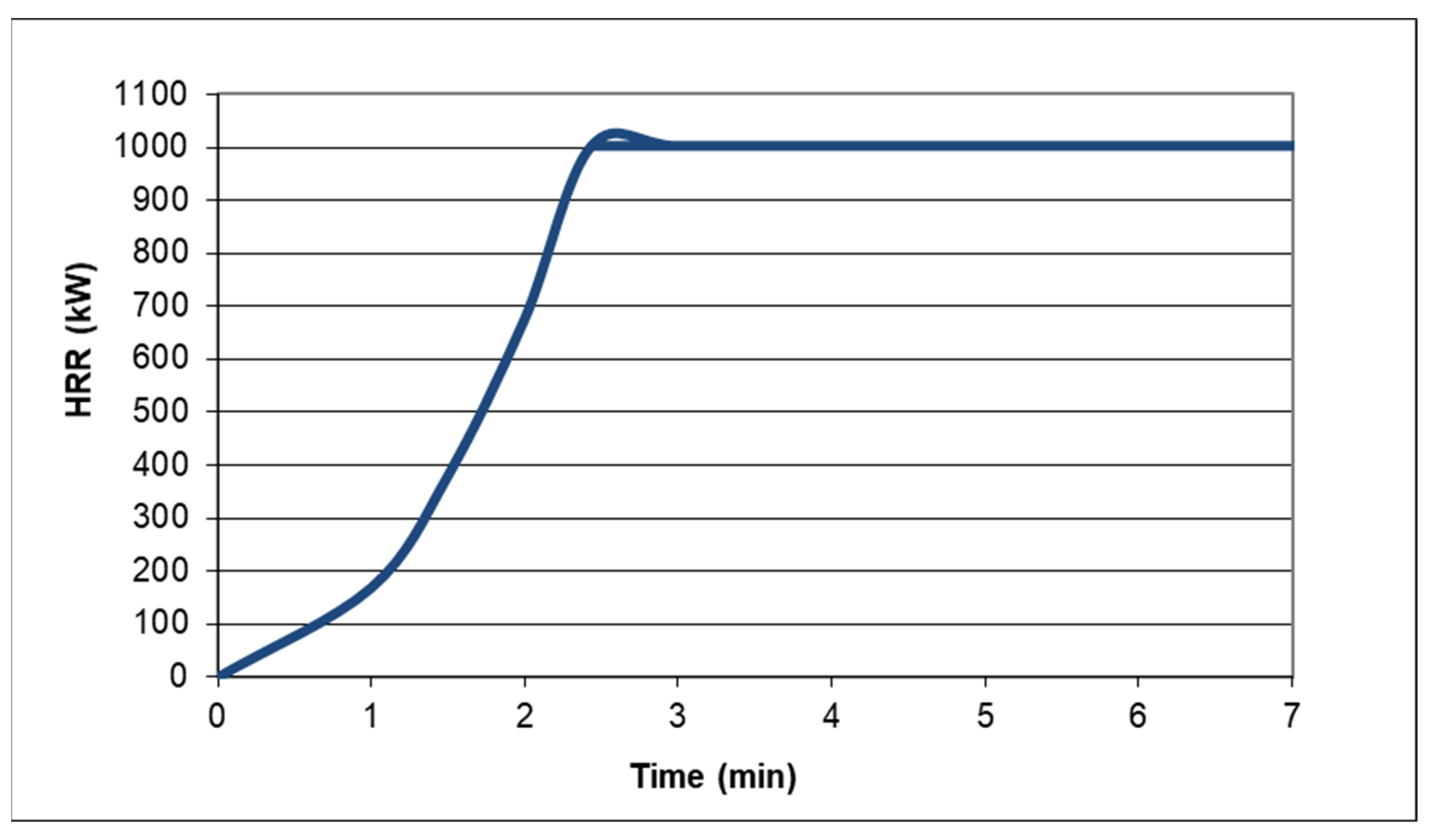
2.3. CFD Computer Simulations’ Boundary Conditions

The first step of the CFD simulations is the definition of the boundary conditions. For the simulations, a computational grid of 0.3 m in the X, Y, and Z directions was adopted. The decision of the mesh size was made based on the mesh sensitivity study, where smaller grids didn’t give appreciable differences in the smoke dispersion results. The material of the building’s construction was concrete, with a density of 2.100 kg/m3, a thermal conductivity of 1.0 W/m·K, and a specific heat of 0.88 kJ/kg·K. In the analyses, the initial external temperature was 20 °C.
Due to the complex structure of a modern atrium structure, especially in the balcony, there may be a variety of combustible materials, such as electrical equipment and cables, etc. However, the worst-case scenario, in this case, would be a reception desk fire, which represents the most significant possible fire load and the lowest position in the analysed atrium. This fire source would be responsible for the biggest volume of potential smoke creation, which would demonstrate the analysed problem the most clearly. A mixture of polystyrene and wood was adopted as the combustible material, representing the mixture of flammable materials which would potentially be present in the reception desk for which the simulations were carried out. The total heat flux of the fire HRR was equal of Q = 1000 kW, as in the hand calculations. The soot yield coefficient was 0.091 kg/kg.
The standard rapid t-squared fire was assumed, based on the fire growth Equations (4) and (5):
Q = αt2
t = Q α = 1000 0.047   = 145   s
Figure 12 presents the curve of the fire growth to the 1000 kW within 145 s, and a steady-state later, up to 7 min, when the evacuation is assumed to be completed.
The simulations were carried out for a time of 420 s from the start of the fire, which is the real time provided for the evacuation of the building users.
On the basis of the simulation, the fire detection time was determined to be around 120 s, and the evacuation was assumed that immediately after such a time (taking into account the additional 20 s which is necessary for the actuation of the devices). Consequently, it was defined that after 140 s from the fire’s start, the smoke vents and supply air openings were opened, and the smoke curtains (special curtains which can automatically go down after smoke detection and prevent smoke propagation to the protected areas) were automatically lowered to the floor. The assumptions were based on the original design parameters of the LabFactor building.
For the verification of the balconies’ influence on the smoke volume production, the fire scenarios were investigated. The third one assumed a fire in the open space of the atrium, the second was partially under the balcony, and the third was centrally under the balcony. The list of the fire scenarios is presented in Table 1.

3. Discussion

Table 2, Table 3 and Table 4 present the simulation results for the analysed fire scenarios. Due to the installation of the smoke curtains at the second and third floors, these floors were separated from the atrium space and protected against smoke propagation. According to the theoretical calculations, the lower smoke layer in the atrium should be located above the first floor. The smoke control system should keep this layer constantly at the height of 7.4 m from the fire source. Table 2 presents visibility slices in the vertical cross-section of the atrium. It can be seen that only in Scenario 1 is the smoke level maintained at the expected level. In Scenarios F2 and F3, when the smoke plume meets an obstacle in the form of a balcony, the smoke level decreases significantly. The decrease is faster in Scenario F3, where the smoke is divided into two similar columns, than in Scenario F2, where most of the smoke flows from one side of the balcony. The different smoke behavior in several scenarios significantly influences people’s safety in the building, which is discussed below.
Table 3 presents visibility slices at the level of 1.8 m from the 1st floor. It can be seen that, in Scenarios F2 and F3, after 120 s from the fire’s beginning, smoke started to propagate in the evacuation corridors on the first floor. In these scenarios, the smoke spread through the corridors very strongly during the next seconds, and visibility decreased below the tenability limit of 10 m. This means that people’s evacuation from this floor could be impossible. Only in Scenario F1, in the expected evacuation time of 420 s, was visibility in the corridors maintained above the required 10 m.
Similar analyses were prepared in accordance with the evacuation conditions on the ground floor of the building, and are presented below.
Table 4 presents the visibility at the level of 1.8 m from the ground floor of the atrium. In Scenarios F2 and F3, it can be found that smoke even propagated into the corridors. However, during the expected evacuation time (420 s), the tenability limit of visibility of 10 m was not reached.
Summarising the presented simulation results, the thesis of this article—that the atrium architecture, especially the additional internal components, can strongly affect the smoke control system’s effectiveness—was proven. This means that smoke control systems’ designers should always investigate the atrium architecture, and should consider all of the elements that could affect the smoke distribution.

4. Conclusions

The smoke control system plays a significant role in sustainable, holistic atrium fire strategies, and the atrium architecture can strongly affect their efficacy. The article presented a method of the use of hand calculations and CFD simulations for these systems. It was demonstrated that traditional hand calculations may not be reliable enough in complex atria. The detailed observation and verification of smoke spread phenomena are possible only through CFD simulations. This can identify dangerous situations for people in a fire through the smoke propagation in the evacuation routes before the evacuation is finished. The presented example shows that a fire located under a balcony causes an increase in smoke production and accelerates the reaching of tenability limits in evacuation routes. Such a situation requires the action of designers and improvements in the first design. An improvement in people’s safety can be achieved, for example, by extending preliminary smoke control system parameters and/or by using smoke curtains at lower levels of the atrium. Additional simulations should verify the new solutions.
This article intended to visualize the fact that the atrium architecture can impact smoke control systems’ effectiveness, and to suggest how to verify this based on CFD simulations. Further works will concentrate on the quantitative approach of the presented problem and the adaptation of standard hand calculation methods to the requirements of contemporary atrium architecture.

Author Contributions

Conceptualization, M.B. and D.B.; methodology, M.B. and D.B.; software, M.B.; formal analysis, D.B.; writing—original draft preparation, M.B. and D.B.; writing—review and editing, M.B. and D.B.; visualization, M.B.; supervision, D.B.; project administration, D.B.; All authors have read and agreed to the published version of the manuscript.

Funding

This research received no external funding.

Institutional Review Board Statement

Not applicable.

Informed Consent Statement

Not applicable.

Data Availability Statement

Not applicable.

Conflicts of Interest

The authors declare no conflict of interest.

References

  1. Klote, J.H. Sustainability and Smoke Control. In Proceedings of the Chartered Institution of Building Services Engineers, London, UK, 13 March 2013; pp. 1–11. [Google Scholar]
  2. Chow, W.K.; Chow, C.L. Evacuation with smoke control for atria in green and sustainable buildings. Build. Environ. 2005, 40, 195–200. [Google Scholar] [CrossRef]
  3. Brzezińska, D.; Bryant, P. Risk index method—A tool for sustainable, holistic building fire strategies. Sustainability 2020, 12, 4469. [Google Scholar] [CrossRef]
  4. Fang, L.; Nielsen, P.v.; Brohus, H. Investigation on Smoke Movement and Smoke Control for Atrium in Green and Sustainable Buildings; Aalborg University: Aalborg, Denmark, 2007; p. 124. [Google Scholar]
  5. Morgan, H.P.; Ghosh, B.K.; Garrad, G. Design Methodologies for Smoke and Heat Exhaust Ventilation; Building Research Establishment (BRE): London, UK; American Society of Heating, Refrigerating and Air-Conditioning Engineers & Society of Fire Protection Engineers: Atlanta, GA, USA, 1999. [Google Scholar]
  6. Klote, J.H.; Milke, J.A. Principles of Smoke Management; American Society of Heating, Refrigerating and Air-Conditioning Engineers & Society of Fire Protection Engineers: Atlanta, GA, USA, 2002. [Google Scholar]
  7. Klote, J.H.; Milke, J.A. Design of Smoke Management Systems; Amer Society of Heating: Washington, DC, USA, 1992. [Google Scholar]
  8. Doheim, R.M.; Yohanis, Y.G.; Nadjai, A.; Elkadi, H. The impact of atrium shape on natural smoke ventilation. Fire Saf. J. 2014, 63, 9–16. [Google Scholar] [CrossRef]
  9. Brzezińska, D. Wentylacja Pożarowa Obiektów Budowlanych, 1st ed.; Lodz University of Technology: Lodz, Poland, 2015. [Google Scholar]
  10. Minister Infrastruktury, Rozporządzenie Ministra Infrastruktury z dnia 12 kwietnia 2002 r. w Sprawie Warunków Technicznych, Jakim Powinny Odpowiadać Budynki i ich Usytuowanie (Dz. U. 2019, poz. 1065 z późn. zm.) [Regulation of the Minister of Infrastructure of 12 April 2002 on the Technical Conditions to Be Met by Buildings and Their Location (Journal of Laws of 2019, Item 1065, as Amended)]. 2002. Available online: https://isap.sejm.gov.pl/isap.nsf/download.xsp/WDU20190001065/O/D20191065.pdf (accessed on 5 March 2022).
  11. Karlson, B.Q.J.G. Enclosure Fire Dynamics; CRC Press: Boca Raton, FL, USA, 2000. [Google Scholar] [CrossRef]
  12. Brzezińska, D. Projektowanie systemów wentylacji pożarowej, a nowelizacja przepisów techniczno-budowlanych [Design of fire ventilation systems and amendment of technical and construction regulations] Ochrona Przeciwpożarowa 4. 2009. [Google Scholar]
  13. Ivanov, M.L.; Peng, W.; Wang, Q.; Chow, W.K. Sustainable smoke extraction system for atrium: A numerical study. Sustainability 2021, 13, 7406. [Google Scholar] [CrossRef]
  14. Ayala, P.; Cantizano, A.; Rein, G.; Vigne, G.; Gutiérrez-Montes, C. Fire Experiments and Simulations in a Full-scale Atrium Under Transient and Asymmetric Venting Conditions. Fire Technol. 2016, 52, 51–78. [Google Scholar] [CrossRef]
  15. Pongratz, C.; Milke, J.A.; Trouve, A. CFD Study Atrium Smoke Control. ASHRAE Trans. 2016, 122, 10–26. [Google Scholar]
  16. Rundle, C.A.; Lightstone, M.F.; Oosthuizen, P.; Karava, P.; Mouriki, E. Validation of computational fluid dynamics simulations for atria geometries. Build. Environ. 2011, 46, 1343–1353. [Google Scholar] [CrossRef]
  17. Kerber, S.; Milke, J.A. Using FDS to simulate smoke layer interface height in a simple atrium. Fire Technol. 2007, 43, 45–75. [Google Scholar] [CrossRef]
  18. Volley, M.K. Verification and validation—How determine the accuracy of fire models. Fire Prot. Eng. 2007. Available online: https://www.nist.gov/publications/verification-and-validation-how-determine-accuracy-fire-models (accessed on 15 February 2022).
  19. Nuclear Regulatory Commission Office of Nuclear Regulatory Research (RES). Verification & Validation of Selected Fire Models for Nuclear Power Plant Applications; Main Report; 2007; Volume 1. Available online: https://www.nrc.gov/reading-rm/doc-collections/nuregs/staff/sr1824/s1/index.html (accessed on 15 February 2022).
  20. Brzezińska, D. Practical aspects of jet fan ventilation systems modelling in fire dynamics simulator code. Int. J. Vent. 2018, 17, 225–239. [Google Scholar] [CrossRef]
  21. Baolati, J.; Li, K.; Zou, Y.; Frank, K.; Hare, G.; Zhang, J.; Ge, F. Large eddy simulation of room fire spread using a medium scale compartment made of medium density fibreboard (MDF) panels. Build. Simul. 2022, 15, 495–510. [Google Scholar] [CrossRef]
  22. Xiao, H.; Makarov, D.; Sun, J.; Molkov, V. Experimental and numerical investigation of premixed flame propagation with distorted tulip shape in a closed duct. Combust. Flame 2012, 159, 1523–1538. [Google Scholar] [CrossRef]
  23. BSI, BS 7346-4. Components for smoke and heat control systems—Part 4: Functional recommendations and calculation methods for smoke and heat exhaust ventilation systems, employing steady-state design fires—Code of practice. 2003.
  24. NFPA, NFPA 204 Standard for Smoke and Heat Venting. 2021.
Figure 1. A convective smoke column: (a) a theoretical free smoke column shape (b) a photo of a free smoke column from the smoke test (photo D. Brzezińska).
Energies 15 02484 g001
Figure 2. Simple atrium examples: (a) a round atrium free of additional internal elements (photograph courtesy of Brzezińska); (b) a long rectangular atrium free of additional internal elements (photograph courtesy of Brzezińska).
Energies 15 02484 g002
Figure 3. Complex atrium examples: (a) beams in the atrium space (photograph courtesy of Brzezińska); (b) balconies in the atrium space (photograph courtesy of Brzezińska).
Energies 15 02484 g003
Figure 4. A multiplied convective smoke column: (a) a theoretical smoke column under a balcony shape; (b) a photograph of a smoke column under a balcony from the smoke test (photograph courtesy of Brzezińska).
Energies 15 02484 g004
Figure 5. The conducted analysis steps.
Energies 15 02484 g005
Figure 6. LabFactor building and its atrium space: (a) external building view; (b) the atrium in the building (photograph courtesy of Brzezińska).
Energies 15 02484 g006
Figure 7. Atrium—Level 0.
Energies 15 02484 g007
Figure 8. Atrium—Level 1.
Energies 15 02484 g008
Figure 9. Atrium—Level 2.
Energies 15 02484 g009
Figure 10. Atrium—Level 3.
Energies 15 02484 g010
Figure 11. A cross-section of the atrium.
Energies 15 02484 g011
Figure 12. The fire growth curve.
Energies 15 02484 g012
Table 1. Fire scenarios.
Scenario F1Scenario F2Scenario F3
Fire in the open spaceFire partly under balconyFire under balcony
Energies 15 02484 i001 Energies 15 02484 i002 Energies 15 02484 i003
Table 2. Visibility in the cross-section of the atrium.
TimeScenario F1Scenario F2Scenario F3Scale
180 s Energies 15 02484 i004 Energies 15 02484 i005 Energies 15 02484 i006 Energies 15 02484 i007
240 s Energies 15 02484 i008 Energies 15 02484 i009 Energies 15 02484 i010
300 s Energies 15 02484 i011 Energies 15 02484 i012 Energies 15 02484 i013
420 s Energies 15 02484 i014 Energies 15 02484 i015 Energies 15 02484 i016
Table 3. Visibility at the level of 1.8 m from the first floor.
TimeScenario F1Scenario F2Scenario F3Scale
90 s Energies 15 02484 i017 Energies 15 02484 i018 Energies 15 02484 i019 Energies 15 02484 i020
120 s Energies 15 02484 i021 Energies 15 02484 i022 Energies 15 02484 i023
180 s Energies 15 02484 i024 Energies 15 02484 i025 Energies 15 02484 i026
420 s Energies 15 02484 i027 Energies 15 02484 i028 Energies 15 02484 i029
Table 4. Visibility at the level of 1.8 m from the ground floor.
TimeScenario F1Scenario F2Scenario F3Scale
240 s Energies 15 02484 i030 Energies 15 02484 i031 Energies 15 02484 i032 Energies 15 02484 i033
300 s Energies 15 02484 i034 Energies 15 02484 i035 Energies 15 02484 i036
360 s Energies 15 02484 i037 Energies 15 02484 i038 Energies 15 02484 i039
420 s Energies 15 02484 i040 Energies 15 02484 i041 Energies 15 02484 i042
Publisher’s Note: MDPI stays neutral with regard to jurisdictional claims in published maps and institutional affiliations.

