Review

Improving Thermal Efficiency of Internal Combustion Engines: Recent Progress and Remaining Challenges

1
State Key Laboratory of Engines, Tianjin University, Tianjin 300072, China
2
Department of Mechanical Engineering, University of Babylon, Babylon 51002, Iraq
*
Author to whom correspondence should be addressed.
Energies 2022, 15(17), 6222; https://doi.org/10.3390/en15176222
Submission received: 10 August 2022 / Revised: 21 August 2022 / Accepted: 23 August 2022 / Published: 26 August 2022

Abstract

:
Improving thermal efficiency and reducing carbon emissions are the permanent themes for internal combustion (IC) engines. In the past decades, various advanced strategies have been proposed to achieve higher efficiency and cleaner combustion with the increasingly stringent fuel economy and emission regulations. This article reviews the recent progress in the improvement of thermal efficiency of IC engines and provides a comprehensive summary of the latest research on thermal efficiency from aspects of thermodynamic cycles, gas exchange systems, advanced combustion strategies, and thermal and energy management. Meanwhile, the remaining challenges in different modules are also discussed. It shows that with the development of advanced technologies, it is highly positive to achieve 55% and even over 60% in effective thermal efficiency for IC engines. However, different technologies such as hybrid thermal cycles, variable intake systems, extreme condition combustion (manifesting low temperature, high pressure, and lean burning), and effective thermal and energy management are suggested to be closely integrated into the whole powertrains with highly developed electrification and intelligence.

Graphical Abstract

1. Introduction

Energy crisis and environmental pollution have become globally increasing concerns. The world has around 1.2 billion passenger cars and 380 million commercial vehicles, and these numbers are expected to increase significantly [1]. Land and marine transport and air transport by jet engines are almost entirely powered by internal combustion (IC) engines. IC engines operating on fossil fuels provide 25% of power generation and produce 10% of greenhouse gas (GHG) emissions [2,3]. Improving thermal efficiency and reducing fuel consumption and GHG emissions motivate the technological progress of the automobile and engine industry. According to the International Energy Agency (IEA) projections, 70% of vehicles will be powered by gasoline engines, and almost all vehicle models will use gasoline or diesel engines for light-duty vehicles and passenger cars in 2030. By 2050, 58% of passenger cars will still use IC engines, with hybrid configuration as an effective auxiliary [4].
To lower GHG exhaust, various emission standards on fuel consumption have been proposed. The National Highway Traffic Safety Administration (NHTSA) and the Environmental Protection Agency (EPA) have jointly developed a national plan for fuel economy standards and GHG emissions in two phases (Phase I: 2012–2016 and Phase II: 2017–2025) for light-duty engines (trucks and passenger cars) [1]. In April 2020, the EPA and NHTSA modified the Corporate Average Fuel economy and GHG emissions standards for light trucks and passenger vehicles, covering model years 2021 through 2026. The target of CO2 lessening for 2025 is a 15% reduction compared to 2021 for light commercial vehicles, while for 2030, the objectives are a 31% reduction for light commercial vehicles and 37.5% reduction for passenger vehicles (see Figure 1) [4]. In Europe, major light-duty vehicle (LDV) markets are targeting 95 g/km CO2 by 2020. In the US, the average reduction rate of CO2 emission for 2017 through 2021 is 3.5 percent per year and 5 percent per year for 2022 through 2025. In Japan, a project named the Research Association of Automotive Internal Combustion Engines (AICE) has been started, aiming at improving the thermal efficiency of a gasoline engine to the level of 50% by 2020. In China, the fuel consumption standard is 6.9 L/100 km for domestically produced passenger cars, which will be lowered to 4.0 in 2025 and 3.2 in 2030.
To meet these stringent regulations, developing more efficient IC engines seems urgent nowadays. Currently, the commercial spark-ignition (SI) engines can work with a brake thermal efficiency (BTE) of about 30–36% [5] and compression-ignition (CI) engines can reach a level of around 42–43% [6,7]. In the brief period, the maximum BTE is expected to be 45% by optimizing established techniques [5,8]. Some studies have expected that the BTC can reach 50% through the integration of various technologies, such as advanced gas exchange (e.g., Atkinson cycles) [9,10], advanced combustion modes (e.g., low-temperature combustion) [11,12], advanced thermal and energy management (e.g., exhaust heat recovery) [13,14], low friction [9], etc. Figure 2 explains the history of the BTE and its future direction. In terms of vehicle systems, the development of engines and conventional powertrains singly can reduce the fuel consumption of LDVs by more than 30%. Compared with the average level, the implementation of other technologies such as lightweight and hybridization can reduce fuel consumption by 50% [15]. Between model years 2017 and 2025, the suggested passenger car demands are expected to increase in stringency from 213 to 144 g/mi, while the demands for light trucks are expected to rise from 295 to 203 g/mi. If all the reductions are achieved, the average fleet-wide (such as medium-duty passenger vehicles, light-duty trucks, and all passenger cars) carbon dioxide compliance level would be 243 g/mi and 163 g/mi between the years 2017 and 2025, respectively.
Currently, IC engines face great challenges of higher efficiency and lower CO2 emissions. Although some numerical and theoretical work has presented a BTE of over 55% [16,17,18], it seems rather difficult for IC engines to achieve the target in realistic situations. Despite this, engine researchers have made great efforts in the improvement of thermal efficiency, where they have devised a future roadmap that includes many advanced technologies and methods concerning combustion, after-treatment, and control systems, as well as partial electrification in the case of hybridization, along with more efficient auxiliary systems and vehicle weight reduction [19]. This review article aims to emphasize the potential of maximizing the thermal efficiency of IC engines and shed useful light on the development direction of advanced engine technologies. A comprehensive review of over 440 references has been reviewed, addressing the recent progress and remaining challenges in the thermodynamic cycles, advanced gas exchange, advanced combustion, and thermal and energy management (see Table 1).

2. The Thermodynamic Cycle of IC Engines

Advanced thermodynamic cycles are of significance in achieving greater engine performance and thermal efficiency. The first and second thermodynamic laws provide the potential and limits for engine thermal efficiency. Starting with the universal expression of thermal efficiency, Otto, diesel, and hybrid cycles are discussed to provide insights into maximizing thermal efficiency. Specific heat is also an important parameter responsible for thermal efficiency. Today, most IC engines in vehicles are operating at a four-stroke cycle with spark ignition or compression ignition. The two configurations have both similarities and significant distinctions [24]. The BTE ( η b ) is a function of four elements [21], as shown in Equation (1), which indicates the ways of maximizing engine thermal efficiency.
η Brake = η Combustion η Thermodynamic η GasExchange η Mechanical
where η Combustion :   combustion   efficiency , η Thermodynamic :   thermodynamic   efficiency   , η GasExchange :   gas   exchange   efficiency , and η Mechanical :   mechanical   efficiency .

2.1. Otto Cycle

The Otto cycle is often applied in SI engines where fuel and air are mixed in the intake manifold or engine cylinder, and then the premixed mixture is ignited actively by a spark plug [418]. When the stoichiometric mixture is compressed, a fuel resistant to the auto-ignition, such as gasoline, must be used to avoid engine knock. Some drawbacks limiting the thermal efficiency of SI engine are as follows:
  • Lower compression ratio (CR).
  • Longer combustion evolution.
  • Gas exchange losses by throttle valves.
  • Lower specific heat ratio.
The theoretical thermal efficiency of the Otto cycle can be determined employing Equation (2) [22,25,26]:
η = 1 C R 1 γ
where CR is the compression ratio and γ is the specific heat ratio. In general, two effective methods are used to improve thermal efficiency. The first one is increasing the CR through enlarging compression stroke or retarding exhaust valve opening timing. The second way is using lean burning to modify specific heat ratios. Dilution combustion is an efficient technique for overcoming engine knock and reducing heat loss. These obvious advantages have motivated the extensive applications of dilution combustion in IC engines in recent years. Nonetheless, engine knock and combustion instability are not solved and stay at the stage of fundamental studies [27].

2.2. Diesel Cycle

Engine combustion with diesel cycle involves complicated, turbulent, and multi-phase processes that take place in high-temperature and -pressure environments [28]. In the intake stroke, only air is introduced into the cylinder, and the reactive fuel is directly injected into the cylinder near the end of the compression stroke to achieve auto-ignition. Thanks to the high compression ratio and the lack of throttle intake loss, diesel engines have a higher thermal efficiency than SI engines [10]. With the fuels tending to spontaneous ignition, diesel engines do not use a spark plug and combustion processes are characterized as diffusion combustion [6]. Despite the advantages in thermal efficiency and reliability, diesel engines are generally associated with the trade-offs between thermal efficiency and pollution emissions, particularly NOx and PM [29]. After-treatment systems, such as Selective Catalytic Reduction (SCR) and Diesel Particulate Filtration (DPF), are often employed in modern diesel engines [23,30].
The theoretical thermal efficiency of the diesel cycle can be determined by Equation (3):
η = 1 1 γ T R γ C R γ 1 γ 1 T R C R γ 1
where CR is the compression ratio, γ is the specific heat ratio, and T R is the temperature of the turbocharger.
Traditional turbocharged diesel engines are usually integrated with a turbocharger where the brake thermal efficiency, thermodynamic efficiency, and combustion efficiency are close to 44%, 50%, and 99.9%, respectively [31,32]. Low-temperature combustion strategies such as homogeneous charge compression ignition (HCCI), reactivity controlled compression ignition (RCCI), and partially premixed combustion (PPC) can deliver higher efficiency than traditional turbocharged engines [33]. However, the LTC concepts are limited by combustion control and load extension, which in turn affects mechanical and gas exchange efficiency. Despite this, low-temperature combustion plays an important role in improving thermal efficiency.

2.3. Hybrid Thermal Cycle

A high-efficiency hybrid thermodynamic cycle can be defined as the configuration integrating various thermodynamic cycles [34]. In this cycle, the air is squeezed into an isolated combustion chamber, enabling true isochoric combustion and lengthy combustion time. Specifically, the compact hybrid thermodynamic cycle adopts rotary pistons and independent revolving combustion chambers. Two pistons spin and reciprocate simultaneously and two roller bearings hold them in place. Intake and compression strokes are carried out by one piston, while exhaust and expansion strokes are done by the other. In contrast to traditional engines, one can expect a decrease in energy losses, moving components, and weight and height [26]. The principal idea is to increase the thermal efficiency of IC engines [35]. The benefits of the hybrid thermal cycle are the possibility of achieving constant combustion volume at higher compression ratios and over-expanding the working fluid. Consequently, more heat energy can be converted into useful work. The main characteristics of the hybrid thermal cycle include [26]:
  • Air is compressed to high CRs like those in the diesel cycle.
  • Constant-volume combustion and isochoric combustion.
  • Expansion volume is greater than compression volume.
  • Water is added optionally during combustion and/or expansion.
The key implementation challenges of the hybrid thermal cycle involve larger mechanical losses, a larger percentage loss of heat transfer, and rousted thermal management for minimizing heat transfer [34].
The theoretical thermal efficiency of the hybrid thermodynamic cycle can be determined by Equation (4):
η t h H E H C = 1 γ r E r C r E γ r C γ
where CR is the compression ratio, γ is the specific heat ratio, T R is the temperature of the turbocharger, r C is the compression ratio, and r E   is   the expansion ratio.
An efficiency comparison has been made assuming that the maximum degree of volume change is identical to traditional diesel engines, with the same amount of heat supplied [25]. The thermal efficiency of the ideal Otto cycle is significantly higher than the actual is that combustion does not happen at constant volume indeed. Under a given compression ratio, the ideal Atkinson cycle has higher thermodynamic efficiency than the Otto cycle and Diesel cycle. Therefore, it can be achieved by the late closure of intake valves. The distinction between actual efficiency and ideal efficiency is less for the hybrid thermodynamic cycle than the Otto cycle because combustion takes place at a genuinely constant volume. Furthermore, the pressure curve slopes down when the piston moves out from the top dead center in the Otto cycle. Therefore, it is reasonable that the thermal efficiency of a hybrid thermodynamic cycle would be closer to or resembling its ideal cycle. An ideal thermodynamic efficiency of the hybrid thermodynamic cycle (62.5% at CR = 18) can be 17% higher than diesel (53.6% at CR = 18) and 19% higher than Otto (52.5% at CR = 12), as shown in Figure 3. Indeed, the ideal cycle efficiency of these engines would be higher than its actual efficiency. Nevertheless, the combustion of the hybrid thermodynamic cycle is carried out in an isolated chamber under the condition of a genuinely constant volume and is permitted to continue significantly longer than in traditional engines.
In another recent study, the effects of the hybrid fuel cell (FC)-ICE cycle on efficiency were examined numerically by Diskin and Tartakovsky [36]. The analysis shows that the hybrid cycle combining electrochemical, combustion, and thermochemical recuperation processes can reach thermal efficiency values above 70%.

3. Advanced Gas Exchange for Improving Thermal Efficiency

3.1. Variable Valve Systems

The intake and exhaust valve systems of an engine are critical subsystems that influence engine performance and thermal efficiency. The major function of the valve actuation system is to regulate the gas exchange into and out of a combustion chamber via intake and exhaust valves, respectively [37]. Valve actuation systems are divided into two categories:
  • Cam-driven systems: cam lobes are used to actuate the valve lift.
  • Cam-less systems: various actuators are used, such as hydraulic, electromagnetic, or pneumatic, to vary valve lift with flexibility in control.
Technical difficulties and commercial issues are some of the challenges that inhibit the cam-less system from being implemented in production. Therefore, the review will be focused on the cam-based systems involving the following:
  • Variable valve lift (VVL).
  • Variable valve timing (VVT).
  • Variable valve duration (VVD).
The VVA adds flexibility to the engine valve train by enabling VVT and VVL events. It can enable a Miller cycle, engine braking, internal EGR, swirl control, variable compression ratio, and improved torque in diesel engines, while in SI engines it reduces the HC emissions during cold start, enables unthrottled operation, and optimizes torque characteristics [44,45]. The VVA system can change the intake valve closing on each cylinder individually using a simple switching valve, which modifies the effective compression ratio [46]. In this case, the VVA system will boost the transient response to illustrate the effectiveness of variable valve actuation. An experimental and simulation study assesses the Miller cycle’s effects on engine efficiency and exhaust emissions [47]. It is found that the application of the Miller cycle negatively affects the BTE at lower engine speed. In contrast, the BTE increases at a higher engine speed and the specific fuel consumption decreases. Further studies showed that very high turbocharger efficiency is necessary for the Miller cycle process to minimize fuel consumption [48]. Recently, Guan et al. [49] found that a highly improved Miller cycle with EGR increased the fuel conversion efficiency by 1.5% at a high load of 1.7 MPa, thus dropping the overall fluid consumption by 5.4%. Advanced combustion techniques based on the VVA could also control the temperature of the exhaust gas and engine-out emissions at low engine loads, as well as improve the efficiency of fuel conversion and total fluid consumption at high engine loads. Possible advantages of the VVA in RCCI engines can be obtained from comprehensive research on HCCI [50,51,52,53,54,55,56], which partly shares the same challenges in terms of load limitation and complicated thermal management for efficient after-treatment systems.

3.1.1. Variable Valve Lift

The amplitude of the valve lift profile, particularly the peak value, is referred to as valve lift [57]. Martins and Lanzanova [58] found that a regular camshaft profile increased global indicated efficiency, but net indicated efficiency was reduced. Flierl et al. [59] designed a fully variable valve lift and timing system. They found that it was feasible to enhance the engine’s fuel consumption by up to 13% compared to the basic engine. On the other hand, Li et al. [60] conducted a comparative analysis between the continuous variable valve lift (CVVL) and VVT on the pumping losses of gasoline engines. The results showed a reduction in the BSFC of CVVL and were more than 20% at 2000 rpm when the lift of the intake valve was maximum.

3.1.2. Variable Valve Timing

Valve timing denotes the phase shift in the crank angle window of the valve lift profile, particularly the valve opening and closing events [61], such as the EVO, EVC, IVO, and IVC. The VVT is to control the timing of an IVC and thus adjust the effective compression ratio (ECR) [62]. Valve timing techniques are used to assist the combustion process and after-treatment system [63]:
  • Early exhaust valve opening (EEVO).
  • Exhaust valve re-opening (2EVO).
  • Intake valve re-opening (2IVO).
  • Negative valve overlap (NVO).
Fuerhapter et al. [56] invented a technique known as the Secondary Exhaust Valve Opening, in which the exhaust valve was designed to be re-opened during the intake stroke. This method was studied for low to intermediate loads for the HCCI engine. The in-cylinder charge temperature was increased efficiently when the hot exhaust gases were re-introduced from the exhaust manifold owing to the second opening. Furthermore, this has achieved the best auto-ignition timing. Sugimoto et al. [64] recorded a 10% decrease in BSFC due to late IVC. In addition, the VVT strategy requires low ECR to control the maximum pressure rise rate (MPRR) at high load [65]. Fallahzadeh et al. [66] registered an increase in BTE for their EIVC engine accredited to a decreased residue gas fraction and thermal transfer. Fuel consumption also decreased by 20–25%, owing to lower pumping loss effects during partial loading, the exhaust gas temperature dropped 4–5%, and the intake manifold pressure rose by 50–60%. Another study observed that the use of VVT in SI engines reduced pumping work up to 36%, and the thermal efficiency was improved by 7.7% [67].
As addressed in the literature [68], the VVT can also bring significant benefits to diesel engines. In the super-truck application, variable IVC timing has been studied as one potential method of improving thermal efficiency to attain flexible control of compression ratio and LTC timing. During the compression stroke, the EIVC lowered the pressure and temperature, resulting in a longer ignition delay. The results showed that the use of the EIVC behaved substantial improvements (~5%) in fuel efficiency and decreased the differential pressure in IC engines. The longer ignition delay increased the fuel quantity in the premixed flame and decreased the diffusion flame magnitude, thereby improving the thermal efficiency [46].
Wu et al. [69] studied the effects of intake valve closing timing (IVCT) on thermal performance and pollution emissions using a two-stage turbocharged diesel engine. Tests were conducted at various loads and engine speeds on a heavy-duty engine. The results showed that the IVCT reduced the difference in intake and exhaust pressure, decreased the loss of pumping, increased efficient thermal efficiency, and minimized pumping work effectively at high speed. A different IVC timings range, covering both EIVC and LIVC, was also evaluated on a “heavy duty compression ignition (HDCI) engine” [70]. The main conclusions are as follows:
  • The EIVC and LIVC strategies reduce the mass flow, thereby decreasing pumping work and improving gas exchange efficiency.
  • The decline of the trapped mass generates a higher combustion temperature and leads to an increase in the heat losses, offsetting the lowering of the pumping work.
  • Since IVC timing has such a poor effect on engine friction, the BTE does not improve significantly or settle constant during tested conditions.
While there are some benefits and challenges in the VVT systems:
  • The uncommon valve lift profiles with EIVC cannot correspond practically with traditional camshafts [58].
  • Solenoid-actuated valves and EIVC can achieve the highest efficiency.
  • The gas exchange process and engine performance can be optimized by utilizing VVL technology [71].
  • It cannot be employed to increase the compression ratio beyond the geometric limit.
Table 2 shows the benefits of using some of the VVA technologies as a single or combination technique in terms of fuel economy. It is observed that the best fuel economy can be achieved through (EVVT + VVL) (~20%), but the cam-less VVA has the better fuel economy (~25%), with its ability to enable the HCCI combustion. Moreover, Figure 4 gives the principle of the VVA technology on natural gas and diesel engines to alleviate some shortcomings while pointing out the knowledge gaps in terms of load range extension, efficiency improvement, and thermal management [72]. It indicates that each VVA strategy has its specific benefit, such as (1) the LIVO for improved combustion efficiency at low loads, (2) the EIVC for extending high load range, and (3) the 2EVO for improved thermal management and combustion efficiency.

3.2. Exhaust Gas Turbocharging

3.2.1. Variable Geometry Turbocharging

Variable geometry turbocharging (VGT) is a very successful method to improve the transient operation of turbocharged diesel engines. Contrary to most other methods, the improvement is achieved by pivoting the angle of the swing blade or by moving the nozzle sidewall, rather than the reduction in the inertia. A combination of improved mechanical innovations such as multiple injections and elevated injection pressures and advanced control have mitigated the noise level concerns mainly in the current generation of common rail designs. The power output has also greatly increased through the use of varying geometry turbines in conjunction with advanced injection technology [76].
η m T C M T M C = G T C d ω T C d t
where M T and M C represent the torque of the turbine and compressor respectively, ω T C is the turbocharger speed, and η m T C is the mechanical efficiency of the shaft.
For advanced diesel powertrains for future trucks, the VGT is of particular interest as they can significantly increase the transient system response to abrupt changes in engine speed and engine load. The VGT systems are also considered to be a key enabler in the EGR system for “heavy-duty (HD)” diesel engines [77]. The main problems associated with the noise level have been mitigated by a combination of improved mechanical, technological innovations, higher injection pressure, and multiple injections [78]. Zheng et al. [79] found that the expansion ratio, pressure ratio, intercooler, and turbine bypass mainly affected engine efficiency, pumping loss, and boost pressure. The results obtained from the experimental analysis of the single and twin-entry VGT designs of automotive turbochargers showed that the twin-entry VGT could allow better use of energy from pulses [80].
The comparisons between VGT and fixed geometry turbocharging (FGT) from the numerical and experimental studies are reviewed by Tang et al. [38]. They reported an improvement in numerous significant aspects comprising transient response, part-load fuel efficiency, load control range, and full-load performance (2–7% for part-load fuel consumption and 15% for full load performance), respectively. Furthermore, the transient response was improved over a broad range in terms of vane controlling as an instance. Furthermore, engine downsizing is an effective technique to improve fuel economy by using a smaller engine to operate at higher efficiency and higher specific engine load. For gasoline engines, turbocharging is more challenging than for diesel engines because of higher airflow variability and higher exhaust temperature. Although the VGT can improve low-end torque, reduce part-load fuel consumption, and afford fast transient response, its cost, durability, and currently allowable turbine inlet temperature are limited. Among the available types of VGTs, the variable nozzle form has the highest efficiency in a wide flow range. In contrast, the variable flow and sliding wall types have lower costs and better reliability [38]. Using the VGT in one turbine compressor setup would be a way to afford the required flexibility, but it increases the entire system’s complexity [58]. In terms of engine efficiency, Wu et al. [81] investigated the effect of the VGT and Miller cycle on six-cylinder heavy-duty diesel engines. The results showed that high thermal efficiency could be obtained by Miller cycles and cooperative control of the VGT.

3.2.2. Multi-Stage Turbocharging

Turbocharging plays a principal role in the development of engine downsizing and down-speeding [82,83,84,85]. There are various benefits to the two-stages turbocharging system over a single-stage turbocharging system. One obvious benefit is the high intake manifold pressures and the corresponding BMEP, the prerequisite for engine downsizing and down-speeding and lessening pumping losses [86]. Other advantages are that the transient performance is improved because a smaller turbocharger is selected as a high-pressure turbocharger [78], and the two turbochargers can cooperate under low load [87]. The disadvantage of this type is the turbo lag, especially large turbochargers, which take time to spool up and provide a useful boost. When considering the operation of two-stage units, especially at low engine speeds, however, the BMEP curve remains unfavorable; hence, turbocharger lag effects are still present [76].
Chadwell et al. [88] tested the effect of the boost method on the function of high-efficiency alternative combustion engines. Their investigation showed that the projected BTE reacted positively with an estimated BTE of 43.6% when the isentropic turbocharger efficiency was improved.
High demands on a turbocharging system are being brought forward by new high-efficiency combustion modes such as PPC [89,90], dilution combustion [91], RCCI [12], and “gasoline direct-injection compression ignition” (GDCI) [92]. The effects of different turbocharger approaches on the transient operating conditions have been investigated [93,94]. The literature shows that the use of electrical turbocharger systems helps to boost transient response and fuel consumption. The two-stage turbocharging system with Miller cycles improved fuel efficiency, which was ascribed to the reduced heat losses at lower combustion temperature and the high-efficiency inter-stage cooler leading to increased pumping work, as shown in Figure 5 [95].
Zheng et al. [79] found that the two-stage turbocharging can achieve a compression ratio of more than 4 bar, which is not effectively achieved by a single-stage unit. Furthermore, a traditional one-stage turbocharger system is commonly utilized to improve fuel efficiency. Additionally, applying an electrical supercharger helps strengthen transient responses and increases the pressure under heavy EGR conditions. Yoo et al. [96] investigated the effects of a two-stage turbocharger coupled with electric supercharge under various engine loads and engine speeds. They observed that BSFC decreased and thermal efficiency increased when electric supercharging was employed. Moreover, applying dual-loop EGR with an electric supercharger can also decrease BSFC by as much as 5.86%. Recently, Wu et al. [97] suggested a method to match two-stage turbocharging to obtain high thermal efficiency for a full range of operating conditions. They found that an enhancement and lowering fuel consumption were achieved when the two-stage turbocharger was matched compared to a traditional single turbocharger.

3.2.3. Electrically Assisted Turbocharging

The electric turbocharger assistance (ETA), mechanically coupled with a turbocharger shaft, offers tremendous opportunities for improvements in fuel efficiency [98]. The ETA is primarily used to boost the transient response and low-end torque that indirectly reduces engine fuel consumption and CO2 emissions [99,100]. It might also be used for the recovery of part of the waste heat by employing electric turbo compounding [101]. It can be considered one of the most appealing solutions as it extracts mechanical energy from the engine exhaust gas to support boost. Therefore, engine downsizing can be achieved by improving transient response [98]. The ETA has several advantages, including eliminating the turbo-lag, regulating the turbocharger speed, facilitating engine downsizing [102], and improving fuel efficiency [103].
Xue and Rutledge [104] provided a comprehensive evaluation of the electric assistance and VGT system to understand and appreciate the potential of electric assistance and a VGT system on both steady-state and transient engine performance. It showed that a higher efficiency was achieved over a broad range of ETA operations, with the ability for engine downsizing from 9.3 L to 7.1 L. Giakoumis [76] observed that selecting the optimal configuration for a particular application depends on many parameters, such as cost, matching process, control system, and engine type, as well as driving cycles. Moreover, even under steady-state conditions, electric-assisted turbocharging can benefit engine performance, while the transient performance of turbocharged diesel engines is worse than that of naturally aspirated diesel engines, especially at low load and low speed. Lee et al. [39] recently confirmed that the ETAs could provide a high boost at low RPM than a conventional turbocharger. The shortcoming was related to the high-temperature influence on the electric machine. Therefore, clutches and a large airgap permanent magnet machine were employed to mitigate this issue.
The hybrid boosting system with the screw-type supercharger displays dramatically improved output at low speed and in transient situations while sacrificing the fuel economy. Compared to a similarly designed dual-stage turbocharging system with a bypass valve, the dual-stage turbocharging system with EIVC demonstrates improved performance and fuel economy. The hybrid boosting system with the VGT shows the best performance in both steady-state and transient conditions and fuel economy. The electrical compressor hybrid system demonstrates excellent performance under steady-state conditions but poor performance due to insufficient electrical power in transient conditions [78]. Figure 6 shows the comparison between various boosting systems and engine baseline in terms of engine thermal efficiency. Noteworthy, these comparisons are based on modeling and estimated results, and it can be noted that the highest thermal efficiency up to 30% can be achieved for mechanical super turbo, followed by electrical supercharging, which exhibits 24.45% thermal efficiency. A similar performance of ~20% can be obtained through activating the control turbocharger, electrical turbo compounding, turbo-super generator, and series sequential turbocharger. Furthermore, the VGT can offer 15% higher thermal efficiency than the FGT, while the series multi-stage turbocharger gives an increase of thermal efficiency of 17% [40]. Alshammari et al. [105] recently observed that although various boosting systems are available, selecting an optimum strategy is still tricky since it depends extensively on the applications.

3.3. Exhaust Gas Recycle

EGR systems can be categorized into internal and external EGR systems. The internal EGR, which is normally uncooled, refers to the trapped combustion product in-cylinder residue and the reverse gas flow between the exhaust manifold/port and the cylinders. The external cooled EGR is typically more powerful for reducing emissions and for elevating fuel economy than the uncooled internal EGR, although the heat rejection must be controlled by the cooling system. High-pressure loop (HPL) EGR, low-pressure loop (LPL) EGR, and hybrid EGR systems are categorized as external EGR [41]. Furthermore, there are also two operating modes for the cooled EGR [42]:
  • A reforming mode involves injecting a small amount of diesel fuel into the EGR stream and then reforming catalytically in the rich combustor to create gaseous fuels like hydrogen for enhancing engine combustion.
  • An oxidation mode in which the products of incomplete combustion are oxidized on a palladium/platinum-based catalyst to reduce the instability caused using EGR.

3.3.1. External Exhaust Gas Recycles

The external EGR is a common method to inhibit in-cylinder NOx generation, which is ascribed to the dilution and thermal effects of exhausted gases [106,107,108,109,110]. The EGR technique is originally employed in diesel engines and then extended to gasoline engines coincidentally with other superior techniques. The cooled EGR can benefit the stable control of low-temperature combustion with low soot and NOx emissions. It may also have the potential to reduce the fuel penalty of diesel after-treatment systems and EGR valve fouling. The rate of EGR needed by an engine change with engine speed and load, and proper regulation of the quantity entering the cylinders is essential for achieving optimal engine performance and minimal NOx emissions. Nevertheless, regulating the quantity of EGR entering the intake manifold does not guarantee that the EGR rate will be spread uniformly throughout the engine’s cylinders [111]. This lead to deteriorating particulate matter(PM) and NOx emissions. Therefore, according to the findings of Pavlos et al. [111], the amount of turbulence in the flow that is produced at the place where EGR diffusion occurs is the primary component that determines how well an EGR mixer functions.
Selim et al. [112] explored the impact of engine speed on thermal efficiency at different EGR ratios and found that as the EGR rate increased from 0% to 5%, thermal efficiency tended to increase insignificantly, particularly at 1600 rpm, while with further increases from 10% to 15%, thermal efficiency decreased due to the degradation of combustion. Duchaussoy et al. [113] compared the role of lean-burn and cooled EGR and found that the cooled EGR was more beneficial than lean-burn in terms of heat exchange and engine performance. The EGR can also significantly improve fuel efficiency in spark-ignited direct-injection engines. Wei et al. [109] observed that the hot EGR could improve combustion efficiency and fuel efficiency by heating the intake charge, while the cooled EGR increases intake density and thereby volumetric efficiency. Hoepke et al. [114] obtained an increase of 5% in gross thermal efficiency using an 18% EGR rate on a boosted “spark ignition direct injection (SIDI)” engine, without obvious knocking tendency due partially to slower combustion. Li et al. [115] analyzed the impacts of cooled EGR on fuel efficiency and found that EGR led to an increase in the specific heat ratio of working gas, diminished the fraction of heat transfer through the cylinder wall, and enhanced the pumping work during gas exchange. Additionally, EGR can advance the combustion phasing, increase the constant volume heat release, and replace the fuel enrichment at high loads. Moreover, there is a 1.1–4.1% enhancement in the BTE by applying 12–17% of the EGR rate.
Zheng et al. [116] found that 47.5% indicated thermal efficiency could be observed at a 30% EGR rate, but when the EGR rate increases to 50%, it descanted due to the prolonged ignition delay, retarded combustion phasing, and the deteriorated combustion efficiency. Liu et al. [117] observed that the indicated thermal efficiency and combustion efficiency were reduced when the premixed ratio is increased from 0% to 50%. However, the increase in premixed ratio permits more fuel to enter cylinder-wall and clearance regions, resulting in more incomplete combustion products. Nevertheless, the combustion efficiency and indicated thermal efficiency exhibit an increasing trend as the premixed ratio increases from 50% to 100%. Figure 7 shows the indicated thermal efficiency as a function of EGR rates. It suggests that there is a significant increase in the indicated thermal efficiency for EGR rate below 30%, which is mainly ascribed to low-temperature combustion. Beyond the critical threshold, the beneficial effect becomes no longer obvious and even decreased due to the deterioration of combustion.

3.3.2. Internal Exhaust Gas Recycles

The intake charge temperature can influence combustion efficiency and exhaust gas temperature [43]. However, a rapid temperature increase of the inlet mixture might not be possible, especially during a cold start and transient operating conditions. Retaining hot residuals from the previous cycle is another successful way of rising in-cylinder and the EGT. This technique is commonly called recirculation of internal exhaust gases [118]. The residual gas fraction can be defined as the mass of the burned gas divided by the total mass of the in-cylinder (burnt and unburnt) before combustion. Factors such as engine speed, valve timing, and pressure differentials depend on exhaust gas quantity trapped within the cylinder.
Mirko et al. [119] observed that iEGR had a more remarkable ability to control EGR in transient operations than external EGR. It was also observed that the use of iEGR moderated combustion by delaying the ignition time, thus eliminating the oscillations of the in-cylinder pressure [120]. Cho et al. [121] reported that the variable exhaust valve actuation with iEGR in diesel engines was beneficial for post-injection.
Pan et al. [122] investigated the influences of excess air ratio on ignition and combustion characteristics under various EGR concentrations as well as the impacts of different iEGR concentrations on ignition and combustion stability of gasoline compression ignition engines. They found that the heat effect caused by iEGR had a significant effect on the ignition stability at low loads. Torque increased first and subsequently decreased as EGR rates increased, with the maximum torque at a 20% EGR rate. Excess air ratio had a similar impact on EGR rates. Torque and combustion efficiency drop when the excess air ratio increases when beyond 3.0, as shown in Figure 8.

3.3.3. Hybrid Exhaust Gas Recycle

It is crucial to optimize the EGR system to attain high-efficiency clean combustion in engines [123,124]. There are numerous EGR systems for EGR implementation such as high-pressure loop (HPL-EGR), low-pressure loop (LPL-EGR), and the combination of two loops commonly called dual loop (DL-EGR) [125]. The HPL-EGR is commonly used in diesel engines owing to its simplified configuration, lower compressor fouling effect, and increased EGR responsiveness performance. By increasing the HPL-EGR rate, the exhaust backpressure is reduced. Consequently, the pressure differential between the intake and exhaust manifold decreases [126]. The HPL-EGR and LPL-EGR have benefits and drawbacks when implemented in diesel engines, which indicates that the simultaneous application of the HP-EGR and LP-EGR has the potential to improve fuel economy [127]. The DL-EGR system, which has both HP-EGR and LP-EGR systems, is being utilized for diesel engines to obtain the best outcomes in the BTE [128]. In contrast, the low-pressure proportion is influenced by engine operating conditions. However, the activation of the LPL is proved to be useful for turbocharger performance, rising its rotational speed and thereby better transient response [129]. As shown in Figure 9, the HPL-EGR capacity to minimize pumping losses declines relative to lower loads for the situation of 1.43 MPa BMEP. The indicated gross thermal efficiency of HPL-EGR also drops faster as the EGR rate rises. If load rises, the indicated gross thermal efficiency diminishing rate exceeds pump losses at a lower EGR rate. In addition, from the comparisons of various engine loads and speeds, it can be found that the BTE of DL-EGR is higher than that of the LPL-EGR and the DL-EGR achieves the highest BTE and low speed under 20% EGR and 1.43 MPa BMEP [128].
A direct comparison of the HP-EGR system and the LP-EGR system was conducted by some researchers [130,131,132]. Park and Bae [127] observed that the HPL and LPL EGR proportions did not influence CA50 and MPRR. Furthermore, the pumping loss tended to decrease with the increased LP EGR portion since the VGT nozzle was opened more widely to sustain the boost pressure, which contributed to the lower BSFC. Cho et al. [133] studied an HPL, LPL, and double-loop EGR and found substantial variations in engine efficiency for different EGR sources. In particular, the double-loop EGR method has the potential to extend the regime for high-efficient clean combustion.
EGR can reduce oxygen availability and extend load range. In advanced diesel combustion systems, internal and external EGR methods have been proved to better form the homogeneous mixture and ignition timing control. In comparison, external EGR is less costly to mount and simplistic to apply, while internal EGR is more expensive to mount and complicated to control in a real engine. Furthermore, the cooled EGR is an effective way in gasoline engines, contributing to suppressing knocking combustion. From the above studies, including e-EGR, iEGR, and hybrid EGR applications, it can be observed that the exhaust back pressure is reduced when using the HPL-EGR. This indicates a decrease in pumping loss and increased thermal efficiency. EGR systems can be improved by the integration of HPL and LPL. The integrated control of these systems offers great potential for improving engine performance and thermal efficiency.

4. Advanced Combustion for Improving Thermal Efficiency

There have been various advanced combustion strategies proposed to improve thermal efficiency. The first section mainly introduces the low-temperature combustion (LTC) modes involving the homogeneous charge compression ignition (HCCI), partially premixed combustion (PPC), reactivity-controlled compression ignition (RCCI), and spark-assisted compression ignition (SACI). The second section mainly introduces the high dilution combustion, including advanced ignition systems, hydrogen-enriched combustion, and thermochemical recuperation. The last one is based on integrated combustion strategies, which involve ultra-high-pressure injection, variable compression ratio, double compression expansion engine, and knocking control.

4.1. Low-Temperature Combustion

The LTC is one of the promising advanced techniques for in-cylinder combustion to minimize emissions with a beneficial impact on high efficiency and specific fuel consumption. It features improved mixture preparation, fuel atomization, reduced combustion temperature, and lower local equivalence ratios, which simultaneously increase the chances of reducing emissions while retaining higher thermal efficiency. The LTC is mostly accomplished through several approaches, namely the HCCI, RCCI, PPC, SACI, etc. [134].

4.1.1. Homogeneous Charge Compression Ignition

For the HCCI mode, a mixture of air and fuel homogeneous or well-mixed ignite without a spark at the end of the compression stroke. Combustion occurs in many locations in HCCI engines due to the self-ignition of the mixture that reaches its chemical activation energy, and automatic combustion occurs without any apparent propagation of flame front or diffusion flame. Furthermore, one-third to one-half of the operating load can be used for SI and CI modes, and the remaining load for HCCI mode.
Polat et al. [150] examine the effects of boost pressure on combustion and output at a low CR of an early direct-injection HCCI engine. The experiments were conducted using n-heptane fuel at various intake manifold absolute pressures from 1.0 to 1.6 bar at different engine loads. As a result, the operating range can be expanded, and the HCCI combustion process can be operated at a low CR of 9.2 by supercharging application. As the boost pressure rose, an improvement in thermal efficiency was seen. The volumetric efficiency, in-cylinder gas temperature, and in-cylinder pressure were increased with increased intake manifold pressure, and the combustion phase was advanced. Therefore, combustion events with CA50 2–3° CA aTDC demonstrate the highest thermal performance, especially under low boost pressures. The test results have shown that the HCCI operating range can be prolonged, particularly at high load limits, by increasing the intake manifold pressure.
Maurya et al. [151] investigated combustion characteristics and emissions of HCCI engines fueled by ethanol under various inlet temperatures of 120–150 °C. The results showed an increase in combustion efficiency, indicated thermal efficiency, and gas exchange efficiency of 97.45%, 44.78%, and 97.47%, respectively, particularly at 393 K of air temperature and lambda 2.5. The low reactivity of n-butanol aids in obtaining optimal thermal efficiencies comparable to conventional diesel combustion (43–46%) is consistently accomplished [152]. Ganesh et al. [153] observed there was a reduction in the BTE when a mixture of vaporized jatropha methyl ester and the air is inserted into the cylinder through the intake stroke. The indicated thermal efficiency of ethanol/n-heptane blend fuels HCCI combustion can be increased up to 50% at high load due to the delay of the ignition timing by the ethanol addition [154,155]. Nagarajan et al. [156] experimentally investigated HCCI with 100% gaseous fuel LPG. They reported that the BTE increased at part loads for all EGR rates, but higher flow rates of EGR negatively affected the BTE at full load.
Because HCCI combustion uses heavily diluted charges with either a high degree of EGR or lean mixtures, the in-cylinder temperature will remain low, comparable to conventional diesel combustion. The principal shortcomings of this combustion mode have been summarized as follows [157]: (i) low power density, (ii) high combustion noise, (iii) limited operating load, (iv) low combustion efficiency, and (v) poor combustion phasing control. In terms of engine efficiency, 15% of thermal efficiency was observed for multiple injections [158]. In Refs. [151,159], 29–37% and 44.78% indicated thermal efficiency was obtained when lambda equals 2.0 and 2.5 respectively. In contrast, the BTE was decreased with vaporizer, and high EGR rate [160], and advanced injection timing [161] and it increased with injection timing [162].
Duan et al. [135] comprehensively reviewed various effective techniques such as fuel reactivity, fuel additives, alternative fuels, reactive species, reforming, and modification, which were used in HCCI engines to control combustion phasing and ignition timing (Figure 10). Main conclusions were found of these strategies applied in HCCI engines summarized as follows:
  • Designing, modifying, and controlling fuel compositions, and employing fuel physical-chemical properties in HCCI engines to improve the combustion phasing and ignition timing and expand operating loads.
  • Fuel reactivity stratification may be an attractive method of controlling ignition timing and reducing the excessive PRR.
  • Fuel reforming and modification were common techniques for adjusting the chemical components to control combustion phasing and ignition timing.
  • As compared to preheated intake temperature, reactive species, and fuel additives have potential advantages in HCCI engines by lowering the intake temperature and making it easier to control the combustion timing.
  • In contrast to conventional gasoline and diesel fuels, alternative fuels have remarkable superior advantages in regulating combustion phasing and ignition timing.
  • Negative valve overlap is an efficient way of increasing in internal EGR of the HCCI engine, which leads to delay in the auto-ignition for high load, hence retard the combustion phasing.
  • Combining external and internal mixture preparation can be considered effective method for controlling ignition timing and combustion phasing.
  • The preheating of intake air and boosting the air pressure can shorten ignition timing and extend the load engine to high. Therefore, the combination of the two ways is commonly used in the HCCI engine.
  • To stratify the temperature distribution in the cylinder of the unburned mixture before auto-ignition, thermal stratification can be used. It is an efficient technique for governing the HRR and controlling the auto-ignition.
  • The combustion phasing and auto-ignition can be controlled using a variable compression ratio instead of preheating the air intake.
  • Applying the SACI mode in the HCCI engine can give an effective approach that operates with lean mixture, controlling combustion phasing, expanding the engine’s load range, and sustaining high thermal efficiency.
Pressure rise rate (PRR) increases as a premixed ratio increases while decreases with vaporizers, high EGR rate, and lean mixtures. Additionally, the maximum PRR was higher without EGR than that with EGR in all pilot quantities as well as it was very high for a rich mixture. This issue can be settled by delayed the combustion phasing to reduce the PRR. Delayed combustion phasing can, however, result in a sacrifice in efficiency. Though HCCI has a limited range of load operations and very rapid PRR due to the auto-ignitions characteristics, a load of up to 2 MPa of IMEP for naturally aspirated can be realized under steady-state conditions, but transient operation conditions remain a challenge. Furthermore, the very rapid pressure rise rate, other parameters can limit the HCCI’s operating range, such as misfiring at low loads and engine knock at high loads. Therefore, numerous strategies are suggested to extend the high load operating limits through turbocharging or supercharging, VCR, SACI, and PPC operation, charge stratification, changing the coolant temperature, variable intake air temperature, VVT, EGR, injection timing, and utilizing alternative fuel with high octane number to avoid engine knock and misfiring [160,164,165,166,167,168].

4.1.2. Reactivity-Controlled Compression Ignition

RCCI is a dual-fuel combustion technique that uses an in-cylinder blend of at least two fuels with various auto-ignition characteristics to control the heat release rate (HRR) and combustion phase [169,170]. The major part of the total injected fuel should be low reactivity fuel (LRF), while the high reactivity fuel (HRF) is utilized to trigger the combustion process [171]. Unlike all other LTC modes, RCCI combustion can achieve significantly higher BTE, with comparatively lower PM and NOx emissions [172,173]. In addition, it facilitates a smoother combustion process by diminishing engine knock [174], which offers good ringing intensity and is better than HCCI engines [175]. The other advantage of RCCI mode combustion is the ability to operate under a wide range of engine loads with acceptable pressure rise, and low ringing intensity, and can produce higher thermal efficiency ~56% [43,176]. Another merit of RCCI combustion is regarded as one of the best promising modes of LTC compared to the other methods and promising technology to improve thermal efficiency under highway navigating conditions. It can also be observed from this strategy for all tested fuels that the heat release rate was higher than conventional diesel combustion [134]. The key benefit of a dual-fuel system is dominating the combustion process by enhancing the blended fuel reaction. To distinguish the combustion process from HCCI or PCCI, led to the term RCCI. The foremost benefits of this strategy include [43]:
  • Low emissions such as NOx and soot.
  • The losses in heat transfer are lessened.
  • Thermodynamic efficiency and fuel efficiency increased.
Although RCCI offers low emissions and high efficiency, it still has numerous challenges, such as excessively high MPRR at high loads and excessive UHC and CO emissions at low loads. These two restrictions limit the RCCI’s working range to moderate loads, making it unsuitable for use in real-world applications [171]. Han et al. [177] showed that PCCI and HCCI combustion modes produced significantly lower soot and NOx emissions, but RCCI mode combustion showed comparatively higher efficiency with superior combustion control compared to other LTC techniques also can have a lower peak pressure rise rate (PPRR) and a longer combustion duration. Notwithstanding the low combustion efficiency, the gross thermal efficiency of RCCI was somewhat higher due to reducing the losses of heat transfer arising from the decline of peak pressure rise rate. The outcomes of pump fuel revealed that it was seen the reactivity of the premixed fuel had increased, and the combustion efficiency was increased to a comparable value to that of the PPC (see Table 3) [178].
Several further studies confirmed that gasoline-diesel RCCI can minimize NOx and soot emissions [179,180,181,182], but the gross indicated thermal efficiency greater than 55% is not replicated. On the other hand, some researchers have reported a remarkably high peak value of 56% at medium loads [43]. Splitter et al. [16] proposed that the gross indicated thermal efficiency of up to 60% was needed with reduced frictional and pumping losses. The findings demonstrate that, with optimization thermodynamic conditions, combustion management, disabling piston cooling, and increasing the compression ratio to 18.7, 60% gross indicated thermal efficiency have been achievable, offering a route to having reached 55% BTE. The BTE is directly proportional to the gross indicated thermal efficiency, where some restrictions can be observed that would reduce the thermal efficiency represented by PMEP and FMEP. Therefore, a maximum BTE can obtain if these losses decreased as much as possible with the possibility of increasing the gross indicated mean effective pressure (IMEPg), as shown in Figure 11. The same authors [183] recorded a maximum GIE of 59% when using PFI of E85 and DI of diesel, with the possibility to extend the load easily compared to their previous work [16]. Additionally, at all tested load points up to 16.5 bar IMEPg, lower EGR rates were needed.
The most important results obtained from the review made by Reitz and Duraisamy [12] were: (i) gasoline/diesel offered high thermal performance over a broad range of load engines, with a maximum GIE of 56% under 0.93 MPa IMEP operating conditions on heavy-duty (HD) engines, (ii) the utilize of E85 and B20 permitted the maximum BTE of RCCI to increase from 40% with the gasoline-diesel operation condition to 43 %. Soloiu et al. [184] observed that RCCI leads to delayed ignition by 7 CAD compared to conventional diesel engines, resulting in a sharper rise in pressure. This strategy increased peak heat release rate (PHRR) and delayed ignition due to reactivity stratification and prolonged mixing time, causing faster flame speeds, as well as an increase in ITE reaching 58% at 4 bar IMEP. Another study conducted by Benajes et al. [185] showed that the thermal efficiency of RCCI operating with E85 was higher than with gasoline. In addition, a higher value of BSFC with E85 than with gasoline. Pan et al. [186] reported that the BTE increased up to 7.08% with 18.5 CR and under high loads due to a decrease in heat loss, resulting from the lower combustion temperature. Similarly, Gross and Reitz [187] reported increased BTE levels of 32.34% at 2300 rpm and 4.2 bar BMEP due to lower combustion losses. Biodiesel/diesel RCCI combustion leads to an increase of BTE by about 31% and reduces cylinder gas temperature due to the better-premixed combustion [188]. Mujtaba et al. [189] numerically investigated RCCI combustion fueled by NG/Diesel to optimize the engine efficiency using AVL-file software. The simulation results observed that 55.05% of GIE was obtained at 13.5 bar IMEPg.
Other significant efforts have been made by Jing et al. [175] to review and summarized the effect of the LRF ratio on the engine performance of RCCI combustion. They found that as the low reactivity fuel (LRF) ratio increased, the engine performance improved. Recently, Butanol Isomers (n-butanol, iso-butanol, and tert-butanol) as an LRF besides n-heptane as HRF, injected directly into the cylinder, have been studied by Han and Somers. Their study was conducted from low to medium-high loads, and the results showed that the highest GIE could be obtained (>52%) with tert-butanol/n-heptane in most operating loads [190]. Pan et al. [191] found that iso-butanol/diesel RCCI has a longer ignition delay (ID), CA50-CA10 and combustion duration (CD), later combustion phasing, lower maximum PRR, and higher ITE, compared with the gasoline/diesel RCCI mode.
Recently, Eyal et al. [192] explored an innovative concept integrating the advantages of High-Pressure Thermochemical Recuperation and the LTC mode. This combination facilitates mitigating pollutant emissions and achieving high thermal efficiency in a wide range. The findings demonstrate a 4- to 9% improvement in thermal efficiency compared to conventional diesel combustion (CDC) with the same engine operating.
In summary, it was observed that LRF such as natural gas is permitted to extend load limits and combustion processes [12]. Moreover, this concept (RCCI) is presented to control better combustion and improve thermal efficiencies than other approaches, such as HCCI, PCCI, single-fuel PPC, dual-fuel HCCI, and PCCI [16]. RCCI combustion also has limitations, such as lessening combustion efficiency at low loads and restricting high load expansion due to excessive PRR [193,194], distributing LRF through port fuel injection (PFI), controlling cycle-to-cycle variation through the transient conditions, modification of fuel injection strategy, and lower exhaust temperatures also pose significant challenges for after-treatment systems. These can be alleviated by improving various control parameters [195] involving VVT, intake air temperature, injection strategy, EGR rate, boost pressure, etc.) [157].

4.1.3. Partial Premixed Combustion

The PPC concept originated from the PCCI engine but is more similar to modern diesel engines [196]. PCCI or PPCI are other acronyms for a PPC. PPC is an LTC concept with its combustion regime sandwiched between HCCI and diffusion combustion [197]. Along with some of the control authority of diffusion combustion, this approach affords low heat loss and pollutant emission. The use of PPC exhibits a significant reduction in heat transfer losses, resulting in an improved engine efficiency [89,198], and its benefits are similar to RCCI [157]. To achieve the PPC, the extension of ignition delay is an essential issue for that purpose, and it can be accomplished by excessive EGR rate, reduced CR, and fuel reactivity [136,162,199,200,201].
Moreover, PPC is a concept that involves fuel stratification to accomplish the desired combustion phasing and ignition timing. Multiple injections and advanced injection strategies are used with this concept to determine the stratification level. Additionally, it endeavors to utilize clean combustion and improved blending of fuels [89]. PPC is an intermediary combustion technique between HCCI and CCM, providing a sufficient ignition delay, hence improving the air-fuel mixture [202]. Combustion has been stratified through PPC, and the fuel-lean, besides fuel-rich regions, decreases NOx and PM emissions without affecting efficiency. Furthermore, fuel injection timing and inlet air temperature were controlled during the combustion stages, although chemical kinetics continues to play a significant role. As a result, more attention has been devoted to the PPC inquiry in recent years [203,204,205].
Manente et al. [206] found that with the use of high-octane fuel in PPC, under high loads of more than 7 bar of IMEP, and 50% EGR, the combustion efficiency was more than 98%. In addition, the values of BTE can reach higher than 48%. Han et al. [207] evaluate the feasibility of employing n-butanol for two types of combustion modes, PPC and HCCI. The results show that both PPC and HCCI of n-butanol can produce low NOx and close to zero smoke emissions while attaining diesel-similar engine efficiency. Zincir et al. [208] investigated the impact of intake temperature on the limitation of PPC at a low load fueled by methanol. The results revealed that with higher intake temperatures, the GIE began to increase (41–42%) because of an increase in combustion efficiency (96–99%) affected by intake temperature. This is attributed because higher intake temperatures under low loads can obtain more complete combustion. Another study conducted by Yin et al. [209] observed that the maximum GIE of 51.5%. When the refinery fuel was used; the GIE was increased up to 50% under high loads and about 45% for the other points. Furthermore, some differences can be observed in increasing and decreasing GIE, especially at the 16–20 bar of IMEPg. This is due to several important reasons [210]:
  • Increase thermal exhaust losses with other residual losses.
  • Combustion was delayed for 20 bar IMEPg due to hardware limitations.
  • Low fuel pressure, extended injection period, and long combustion duration.
Numerous studies reveal that the advanced SOI leads to decreased cylinder pressure and HRR [161,211], and the others show an increasing cylinder pressure and HRR [212,213]. It is observed sometimes increasing and sometimes decreasing, and this also includes BTE and BSFC. The reason is that each study has its operating conditions, such as engine type, injection pressure, injection type, fuel type with its blend, EGR rate, etc. In summary, the BSFC was increased in most studies because they depend on several parameters. On the other hand, an increase in BTE and combustion efficiency can be demonstrated because the combustion process of the PPC is very sensitive to boundary conditions.
The optimization of charge stratification is considered one of the essential factors to improve combustion performance, and it can be achieved by employing multiple injection strategies. Zhang et al. [214] analyzed the multiple injection strategies utilizing thermodynamic approaches to study how the combustion phasing, the heat release energy, and the heat transfer loss affect the GIE of PPC combustion in heavy-duty optical engines. The results showed that a higher GIE could be obtained in the late double injection with a later combustion phasing compared to the early double injection cases and 47.9% of GIE for the triple injection case. In addition, the interaction between the post-injection and main combustion was a critical point for combustion efficiency, although less influence on the combustion phasing. Additionally, Mao et al. [215] explored a multiple-injection strategy to achieve the highest BTE of 44% in a multiple-cylinder heavy-duty diesel engine [215]. Recently, Aziz et al. [216] investigated a multiple injection (double and triple) strategy on the performance of PPC at low load fueled by Methanol in a single-cylinder heavy-duty engine. They found that the GIE was improved using multiple injection strategies compared to a single injection. Another recent study was conducted by Dimitrakopoulos and Tuner [217] to reduce the high combustion instability (COV) at a low load of Gasoline PPC using glow plugs. The results showed that inlet air temperature was reduced by glow plugs, hence keeping the combustion stable and having an insignificant effect on efficiency.
In summary, the PPC can provide better mixing before the combustion since it is based on the prolonged ignition delay. Although PPC has many merits over HCCI, it presents some critical challenges related to combustion stability and controllability, high HRR, high PRR at low and medium loads, as well as poor combustion efficiency at low loads. Using multiple injections and throttling the engine and running at a lower lambda, RCCI and SACI are likewise methods to resolve the poor combustion efficiency at low loads. For high loads, further investigations are required to use oxygenated fuel with a high CN, glow plugs, high boost pressures, high EGR ratios around 50%, advanced injection strategies, and placed the main injection nearby TDC.

4.1.4. Spark-Assisted Compression Ignition

The SACI is an efficient strategy proposed to optimize the robustness of ignition control, achieve stable phase control, and extend the HCCI load range [218,219]. SACI strategy is based on a lean mixture via injecting fuel within the combustion chamber through the early intake stroke. An external ignition source was utilized to initiate a flame front propagation, and compression ignition is initiated by exceeding the auto-ignition threshold. The auto-alignment threshold relies on the air-fuel mix, fuel type, and residual gas amount [220]. The purpose of SACI is to achieve supplementary HCCI combustion control. SACI is an intermediary concept involving flame improvement initiated via spark discharge, accompanied by HCCI kinetic combustion. A spark discharge has been added to improve combustion stability in terms of the IMEP [221]. The combustion properties of HCCI, SACI, and SI mode were contrasted by Wang et al. [222]. They have found that SACI can attain higher thermal efficiency than spark ignition combustion, particularly at 8.2 bar of IMEP.
Many researchers have expanded the engine loads into the SACI system by modulating some variables [219], such as spark timing [218], internal and external EGR rates [223], intake temperature [224], and effective compression ratio with LIVC [54]. Chiodi et al. [137] have shown that ~44% indicated thermal efficiency is considerably higher than that of flame propagation combustion and reduces specific fuel consumption to a minimum. This rapid energy release results in the highest peak pressure, even higher than the limited flame combustion without knocking. This is noteworthy because the total energy released is substantially higher due to the lambda value being richer. Ortiz et al. [225] noted that the combustion strategies for HCCI and SACI showed potential increases in the ITEnet of up to 30%, with an additional 12.5% with the potential to incorporate less detrimental control strategies, as shown in Figure 12. Yun et al. [226] showed that the ignition delay became shorter due to the delay in spark timing, meaning that the beginning of the combustion would be rapid. Finally, using the spark assisted HCCI combustion, the operating range was extended. Furthermore, under higher load in SAPCCI mode, the BTE of low-octane fuel is better than the baseline G100 (~43%) [227].
Zhou et al. [228] showed that the iEGR ratio and ignition timing were essential factors for controlling the SACI combustion process. As a result, iEGR principally controls the combustion phase by varying intake air mass flow and the initial in-cylinder temperature. To accomplish stable SACI combustion and overcome ringing, Chen et al. [229] employed late side injection to adjust fuel distribution. They found that controlling the peak HRR value between 81.72 J/CAD to 148.92 J/CAD can result in stable SACI without ringing. In addition, the late side injection strategy decreases auto-ignition flame speed, suppresses engine knock, and improves thermal efficiency, thereby realizing SACI combustion. Jacek et al. [230] explained how the SACI achieves appropriate PRR and combustion stability under high load boundary conditions, which was beneficial to the HCCI/SACI transition. The results showed the ability to operate SACI at IMEP of 5 bar with an SFC of 207 g/kWh for heavy-duty engines. It is essential that the PRR and variation of IMEP do not exceed 2.5 bar/CAD and 3%, respectively, thus affording the considerable potential of load extension. Biswas and Ekoto [231] concluded that the impact of ozone addition was more significant for the low loads. Moreover, ozone addition decreases specific fuel consumption by up to 9%, with enhanced combustion stability comparable to similar conditions without ozone.
Recently, a comprehensive review has been conducted by Robertson and Prucka [232] to determine the key factors required to realize a feasible production-workable control strategy for SACI engines. The literature demonstrated that brake thermal efficiency of up to 44% was achievable in the product. The efficiency advantages are determined by the increased compression ratio, higher specific heat ratio, reduced pumping work, lower heat transfer, and shortened burning period. They found that charge stratification can achieve flame propagation and reduce the auto-ignition of the reaction rates.

4.1.5. Summary of the LTC Modes

As addressed in the above studies, the LTC mode has faced several challenges such as load extension and control of the knocking at high load [134]. First, combustion control and ignition timing. Because this combustion mode is ruled by chemical kinetics, it is extremely complicated to control these parameters. However, combustion can be governed by the temperature-time history of the fuel-air mixture and the fuel’s properties. Temperature-time history can be altered by adjusting the intake air temperature, VCR, EGR, etc. The second is combustion stability and its noise (misfiring and torque oscillation). The use of closed-loop combustion control can mitigate this issue by regulating combustion timing, such as ignition delay and peak PRR. The third is combustion phasing, which is based on the signal of in-cylinder pressure. Fourth, cold start. Three methods can resolve this issue, such as providing glow plugs, utilizing some fuel additives, and adding vaporizer to biodiesel fuels. Finally, an extension of the highest possible load limits. To overcome this issue, two ways can be adopted, e.g., adaptation booster and compound injection strategy and using diesel blended renewable fuel such as ethanol and biodiesel.
Among the different LTC technologies, it was observed that intelligent charge compression ignition (ICCI), which is not covered in this article, has unique merits and potential in high efficiency (up to 50% of ITE at medium loads), combustion efficiency is significantly higher at low loads, and low emissions under wide load range over other LTC modes, so it is a suitable combustion mode to overcome high MPRR at high loads and low efficiency at low loads. ICCI can be enhanced in-cylinder reactivity, reformulating the cylinder’s concentration stratification and composition at low loads [233]. Thus, that is why this concept can produce higher thermal efficiency. Maybe soon the ICC mode will be attractive in commercial applications.

4.2. Highly Dilution Combustion

Highly dilution combustion has been known to afford advantages for higher thermal efficiencies and lower emissions [234]. High dilution is one type of LTC strategies improve efficiency by reducing pumping work and heat transfer, as well as increasing the ratio of the specific heat. However, the high dilution harms deflagration flame propagation, raises the ignition energy required for auto-ignition, and limits peak engine load [232]. Some innovative strategies have been proposed to overcome these drawbacks, including an advanced ignition system, hydrogen-enriched combustion, and thermochemical recuperation.

4.2.1. Advanced Ignition System

Advanced ignition systems have been studied as a technology for downsizing boosted engines with dilution combustion. These technologies comprise [235]:
  • Laser ignition.
  • Microwave high-frequency ignition.
  • Dual-coil offset/ignition.
  • Active and passive jet ignition.
  • Multi-charge ignition.
Advanced igniting systems for gasoline engines are necessary to improve engine thermal efficiency under dilution combustion conditions [138]. In addition, many of these systems improve the combustible mixture’s ignition energy or dispersed the ignition energy into the entire combustible charge [139]. Due to the plenty and complexity of ignition technologies, only three types will be discussed and briefly summarized here, and the scope of their impact on thermal efficiency is as follows:
  • Laser ignition system (LIS).
  • Low-temperature plasma (Corona ignition system (CIS).
  • Turbulent jet igniters (TJI).

4.2.2. Laser Ignition System (LIS)

It has been pointed out that the LIS can raise the peak cylinder pressure by 5% and 15% on average, respectively [236]. The laser source that is used to initiate combustion has several potential advantages. Although there are still some limitations, they have come to be an attractive research field to substitute conventional electrical discharge systems [139,236,237,238]. The main advantages of the laser ignition system are:
  • It is an electrode-less ignition system.
  • No electrodes were eroded or quenched effects.
  • A laser ignition system’s lifetime will far surpass the spark plug’s lifespan.
  • Random position of ignition plasma, capability for the leanest mixture, and precision ignition timing.
Laser ignition can precisely control the ignition energy deposited in the ignition plasma and feasibility multi-point ignition easily. These advantages of laser ignition have great potential in practical applications and could be used dramatically to improve the combustion process, which has increased research about laser ignition in the past few years [140]. One of the significant advantages of LIS is that it is easy to perform multi-point ignition, which is essential to burn lean mixtures, overcome the loss of flame speed, and reduced combustion duration [141,239,240,241]. The various strategies to implement multi-point laser ignition in a constant volume chamber of an engine have been studied [140,242,243]. The possibility of multi-point laser-induced ignition has been proved for the combustible mixture for either constant volume [240,241,243,244] or IC engines [245,246,247]. A significant improvement in the combustion of a lean mixture has been obtained by igniting the mixtures at multiple positions. An increment in peak pressure and PRR was seen for multi-point laser ignition compared to the single-point ignition.
Bihari et al. [248] observed that laser ignition improved combustion stability under all operating conditions; furthermore, they noted that the lean ignition limit could be significantly extended. The study also found that the BTE obtained was 32% when the laser ignition system is applied. Pal and Agarwal [249] observed that the BTE improves for both LIS and SI with BMEP rise. Additionally, the superior combustion of the hydrogen-air mixture within the combustion chamber is associated with higher BTE. Furthermore, this results in higher combustion efficiency inside the combustion chamber and a higher BTE for laser ignition (LI) than SI. Patane and Nandgaonkar [140] have reviewed several technologies utilized for multi-point laser ignition. They found that the increase in laser energy indicates improved combustion characteristics.
Recently, Prasad et al. [250] found that a maximum BTE is obtained for 31° CA bTDC ST (spark timing) for all hydrogen-compressed natural gas (HCNG) mixtures, and it was reduced for both advanced and retarded sparking timings. This experimental study also shows that laser ignition is proper for HCNG engine deployments.

4.2.3. Corona Ignition System (CIS)

In the past few years, radio frequency (RF) corona ignition technology has attracted much attention. The benefits of the corona ignition system (CIS) comprise continuous energy delivery, large ignition volume, and the feasibility of combustion diagnosis. In addition, the CIS can promote near-simultaneous and near-located multiple ignition points, thereby reducing the (0–10) burning duration [251]. A high-frequency power supply, a resonant igniter, and corresponding network circuits are the key elements. Therefore, the CIS can make combustion stable and extend engine operating range and lean stability limits compared to other ignition systems [252,253,254,255]. In comparison to the conventional spark ignition systems, the CIS can create a significantly larger high-intensity plasma ignition source, as shown in Figure 13.
Several studies demonstrated that the early flame propagation had been accelerated, and the dilution limitation was extended, resulting in more stable operation, improved fuel economy, and provides further efficiency benefits [235,256,257,258]. A less than 3% of the “coefficient of variation. (COV) of IMEP (COVIMEP)” and shorter ignition delay can be obtained using an advanced corona ignition system (ACIS) [235]. In addition, it was noted that the flame propagation, ignition, and flame kernel generation were more robust [251]. Moreover, the ACIS enables advanced combustion strategies like highly diluted mixtures, very high EGR, and lean-burn, further increasing fuel efficiency [419].
Recently, experiments had been conducted in a single-cylinder optical research engine through Biswas et al. [420] to investigate the effect of three types of ignition systems on the performance and emissions, including ACIS, barrier Discharge Igniter, and Nanosecond Repetitive Pulse Discharge (NRPD). The experimental outcomes revealed that the lean limit was extended in both ignition systems (ACIS and NRPD), where the COVIMEP is less than 3% [420]. Another study conducted by Ricci et al. [259] showed that corona igniters can extend. the lean. stable limit by increasing the early flame growth speed.
In summary, among the non-thermal plasma ignition techniques, the CIS shows the most possibility for adapting to changing in-cylinder thermodynamic conditions. In contrast, one of the CIS challenges ensures corona discharge’s inception while avoiding arc touchdown, particularly in high-density conditions if a higher voltage is necessitated [138].

4.2.4. Turbulent Jet Igniters (TJI)

Another promising approach for improving dilution combustion is the pre-chamber technique with an auxiliary fuel supply system, usually called turbulent jet ignition (TJI) [260]. The TJI systems can be categorized into passive pre-chamber systems, in which the fuel is supplied externally into the pre-chamber, and active pre-chamber systems, in which fuel is injected inside the pre-chamber. A passive pre-chamber consisting of a cover with holes encapsulated a smaller volume of fluid. As shown in Figure 14, the pre-chamber is linked to the main chamber through one or more tiny orifices (~1.25 mm diameter) [421]. This leads to promoting the quenching of flame and penetration into the main chamber. The main chamber combustion is initiated by the reacting mixture of pre-chamber in multiple locations throughout thermal, chemical, and turbulent influences [142,261,421].
The spark plug electrodes are utilized as an improver of ignition energy for the main combustion chamber [143,262]. The mechanisms behind the TJI combustion include the intricate coupling of factors [263,264], such as turbulent mixing, chemical reaction, flame quenching, and flame-piston impingement [265]. The TJI has the merits of enhancing burning rates and extending gasoline engine lean-burn limits. Some experimental studies by Refs. [261,266] reported an ITEnet of 42% using the TJI system, and it is an efficient way to extend the knock limit. Another work made by Bueschke et al. [267] proved that using the TJI leads to developing flame front, and a short combustion duration has been obtained. Furthermore, ultra-lean combustion and best fuel consumption can be achieved as well as improved engine performance by utilizing a fueled pre-chamber, which indicates that the TJI is more feasible for engine combustion under partial load conditions [260].
The TJI could be considered one of the solutions for increasing the flame speed and stabilizing the combustion process. Hua et al. [268] conducted experiments in a single-cylinder gasoline engine with different ignition systems, involving one-hole TJI, twin spark ignition, single spark ignition, and seven-hole TJI under various air/fuel equivalence ratios and various engine loads. The results showed that the cycle-to-cycle variants of the TJI combustion assessed by the COVIMEP and coefficient of variation (COV) of peak pressure are significantly reduced due to the rapid combustion rate caused by the jet flame. Additionally, the single-hole TJI combustion seems to have the best combustion stability, particularly lowering COV of peak pressure.
Recently, Distaso et al. [269] analyzed the combustion by implementing the numerical simulation for the active pre-chamber technique of a lean operation engine. The analysis indicated that the overall operation of the TJI with an active pre-chamber could be subdivided into six principal phases, described as mixing, flame propagation, filling and scavenging, ejection, re-burning, and extraction and expulsion. At the TDC, approximately 40% of the cylinder volume has been occupied by flames, while traditional spark plugs only reported 18%. The results revealed an improvement in the engine performance compared to conventional spark plug when using a TJI system in terms of efficiency.

4.2.5. Hydrogen-Enriched Combustion

Hydrogen enrichment can significantly increase efficiency while reducing emissions without extensive engine modifications. One option for enriching the hydrogen source is to produce hydrogen on the vehicle through steam reforming methane actively [270]. The speed of the hydrogen flame is nine times greater than that of the diesel flame. Therefore, diesel combustion in the presence of hydrogen would achieve more fast and more complete combustion [271]. In addition, hydrogen is considered a high energy source because of the higher heating value, higher flame speed, low ignition energy, and the fact it does not have carbon atoms. These characteristics make it an essential source for emission control and the CI engine’s performance improvement [144]. A mixture of hydrogen and methane showed that CO, CO2, and HC decreased with the increase of hydrogen percentage while NOx increment [272]. Excessive air ratio fueled with methane and hydrogen showed that the maximum PCP decreased with an increased excessive air ratio [273]. On the other hand, under injection timing of 5° ATDC with an injection duration of 90°, the BTE increased from 23.6% to 29.4% compared to diesel due to better mixing of hydrogen with air, resulting in enhanced combustion. Although 31.67% of the BTE can be achieved at 15° ATDC with 60° CA, an engine knock issue has been observed at this condition [274].
Karim et al. [275] reported that with increasing hydrogen content share, BTE had increased. Another study was conducted by Akansu et al. [274], and their conclusions were similar. Bari and Mohammad Esmaeil [271] observed that the BTE improved from 32% to 34.6%, 32.9–35.8%, and 34.7–36.3% at 19, 22, and 28 kW, respectively, by increasing the percent induction of H2/O2 mixture enrichment. This will lead to higher peak pressure near the TDC and generate a higher effective pressure for the work to be done, thereby contributing to efficiency improvements. Deheri et al. [144] revealed that the use of biogas in diesel engines decreases the BTE by up to 13% while increasing fuel consumption by up to 36%, which can be enhanced by using such techniques as advanced injection timing or higher compression ratios up to 10 to 12 %. In contrast, the combustion duration and ignition delay can be reduced by simultaneously providing biogas and hydrogen to the cylinder with advanced injection timing and higher CR. It appears that owing to the large flammability and high hydrogen flame speed, after hydrogen enrichment, the BTE at a lean-burn limit has been increased and reaches its maximum value of 18.99% when the fraction of hydrogen volume is one percent [276].
Zareei et al. [277] conducted a simulation study of a diesel engine fueled with hydrogen-compressed natural gas (HCNG) (the hydrogen amounts used in HCNG are 10, 20, 30, and 40%) using AVL Fire software based on the method of finite volume. The results reveal that the BTE has been improved when the concentration of hydrogen in the HCNG blend increased compared to CNG and pure diesel. This is because of the higher diffusivity of hydrogen (a homogenous mixture between hydrogen and air would be better). The BTE has increased up to 8.44% and 14.85% at 2400 and 1200 rpm, respectively, by utilizing 40% hydrogen in the HCNG blend compared to pure diesel, as shown in Figure 15. Alrazen et al. [145] analyzed the effect of the hydrogen addition to diesel engines on the performance and emissions. Therefore, an increase in BTE was observed due to short combustion duration, increased heat release, and cylinder pressure caused by hydrogen addition. In brief, hydrogen addition can help to enhance the poor combustion process of natural gas, which reduces the ignition delay, and improves the flame propagation speed, peak HRR, and peak cylinder pressure. Nevertheless, it also leads to a pinging sound and engine knock [278,279].

4.2.6. Thermochemical Recuperation

One viable method of waste heat recovery (WHR) to utilize the energy of the hot exhaust gas to maintain the endothermic fuel reforming reaction is defined as thermochemical recuperation (TCR) [280]. The TCR has two main advantages. First, through the endothermic fuel reforming reaction, the LHV of the fuel is increased due to the WHR process. Second, the mixture of gaseous reformed products usually has a higher hydrogen content, which increases burning velocity, a higher octane number, higher resistance to engine knock, and a more comprehensive range of flammability limits [281,282]. Therefore, the TCR can improve the efficiency due to the WHR process and lean burn operating feasibilities, thereby improving the ICE efficiency, approaching the theoretical Otto cycle, and the potential for increasing its compression ratio.
Popov et al. [283] have concluded that the TCR would improve energy efficiency by up to 10–25% compared to the traditional recuperation systems. Pashchenko et al. [284] analyzed the first law energy analysis of TCR by steam reforming several liquid biofuels, especially methanol, ethanol, glycerol, and n-butanol. The maximum efficiency of TCR use is at 600, 700, 850, and 900 K for methanol ethanol butanol, and glycerol, respectively. The results revealed that it was possible to choose the type of fuel owing to steam reforming, and it could be used for the first law energy analysis of the TCR system by steam reforming of liquid biofuels. However, Chakravarthy et al. [280] demonstrated that for a stoichiometric mixture of methanol and air, TCR could improve the ideal engine’s second law efficiency by over 5% and about 3% for volume reforming and constant pressure, respectively. Furthermore, for ethanol and isooctane, the estimated second law efficiency increased by 9% and 11% for constant volume reforming, respectively. Brinkman and Stebar [285] indicated that the improved thermal efficiency resulted from the advantageous characteristics of H2-rich methanol-reforming products, such as broader flammability limits and higher burning velocity, compared to gasoline.
As can be seen in Figure 16, employing the high-pressure methanol steam reforming (MSR) of 26 bar or higher and DI injector reference flow diameter (IRFD = 3.84 mm) affords engine efficiency enhancement of 12% to14% in comparison with the gasoline-fed counterpart. Additionally, the predicted improvement in the engine thermal efficiency will be much higher under partial loads. This is due to the lean-operating feasibilities permitted via the high hydrogen content in the reforming products [286]. Previous simulations have also shown that engine fueling with ethanol decomposition and methanol steam reforming (MSR) products reduces pollutant emissions more than gasoline [287].
Another study by Poran and Tartakovsky [288] revealed that the engine feed with high-pressure methanol steam reforming leads to an improvement in an ITE of 18–39% (as shown in Figure 17), compared with gasoline feeding. Generally, the reformatted fuels have revealed a significant enhancement over gasoline in combustion performance, such as reducing COV for quicker HRR and a wide range of EAR. Tartakovsky and Sheintuch [289] provided an inclusive review of research on fuel reforming for IC engines. It involves a discussion of factors to consider before choosing the primary fuel. Steam reforming provides moderate thermochemical recovery and is suitable for methanol and ethanol feeds. Air reforming reduces the degree of recuperation but opens up opportunities for utilizing heavier fuels (like diesel and gasoline). Dry reforming (with carbon dioxide) can provide the best recuperation, but it is vulnerable to rapid coking.
Recently, Hwang et al. [290] experimentally studied a “novel thermally incorporated steam reforming TCR reactor, which utilizes sensible and chemical energy in the exhaust to afford the required heat for hydrous ethanol steam reforming. Off-highway diesel engines were run at three different speeds and loads with diverging hydrous ethanol flow rates arriving fumigated energy fractions of up to 70%”. The results show that the engine combustion and thermal efficiencies have suffered under low load conditions but exceeded conventional diesel combustion (CDC) values during high loads. The increase in operating temperatures permits CDC, such combustion efficiencies, while providing sufficient heat to generate a more significant energy content stream. In summary, TCR has significant benefits for improving IMEP and engine efficiency. Still, further research endeavored to improve IC engines’ startup, and transient behavior with the TCR is needed to extend the range of feasible applications.

4.3. Other Advanced Technologies and Strategies

4.3.1. Ultra-High-Pressure Injection

Higher pressure injection has become a practical solution as implementing electronic fuel injection apparatus promotes engine performance and reduces emissions. In the past few years, 100 MPa injection pressure with an inline or a rotary pump system has been considered high pressure. However, in recent years, the pressure has risen to 160~180 MPa and even beyond 200 MPa. Likewise, engine power output was increased due to lower ignition delay duration at high injection pressure, leading to better BSFC [291]. On the one hand, raising the injection pressure enables increasing engine efficiency and decreases fuel consumption [292].
Researchers in diesel engine manufacturing start to talk about “30–300–3000” technologies as prospect trends, i.e., “30” represents high power density (30 bars of BMEP), “300” means 300 bars of peak cylinder pressure (PCP) to promote high thermal efficiency; and “3000” represents maximum fuel injection pressure in bar for governing NOx, soot, and enhanced combustion efficiency [6]. Nowadays, the injection pressure has attained 2500–2700 bar [293], and a few studies have attempted to create fuel systems with 3000 bar injection pressure (Delphi, Denso). Gumus et al. [294] show that the increased injection pressure provided better outcomes for BTE and BSFC. Additionally, 41.31% of BTE was obtained with the B100 for 240 bar injection pressure. To obtain better diesel performance, some authors even put forward average suggestions on how to change the injection pressure [292]. High pressure directly decreases the diameter of droplets. This helps shorten the most prolonged combustion phase. Lee and Park [295] investigated atomization processes, spray break-up, droplet diameter, and velocity from a gasoline direct injector fueled with n-heptane under high injection pressure up to 300 bar. They affirmed that the injection pressure plays a crucial role in droplet breakup, but there is a limitation in injection pressure to improve droplet breakup.
Several studies have been conducted using an “ultra-high injection pressure” or “micro-hole nozzle” with its effect on the engine performance and emissions characteristics [296,297,298]. However, fuel injection equipment with “ultra-high-pressure injection” is still being created [299,300]. Li et al. [301] concluded that, for GDI injectors that use ethanol fuel, the “ultra-high injection pressure” up to 300 bar is a potential method to improve the homogeneity of the air/fuel mixture. The specific power must be increased concurrently with an increment in the injection pressure [302]. Mohan et al. [291] studied the effect of fuel injection strategies on improving engine performance and emissions control. They noted that increasing fuel injection pressure could improve fuel atomization and enhance the combustion process and thus increasing BTE. Aoyagi et al. [303] found that the merge of high EGR rate and high boost pressure as well as the high injection pressure up to 200 MPa is a practical and effective strategy that can simultaneously reduce the exhaust emissions and fuel consumption of diesel engines. They also observed that the BTE can be obtained at 46.3% and 49.7% under the PCP of 28 MPa and advanced the start of combustion (SOC) to −6° ATDC for single and six-cylinder, respectively.
The influence of “ultra-high injection pressure” on diesel ignition and flame characteristics was numerically studied using the KIVA-3V code with the KH/RT spray breakup model [304]. Due to the in-cylinder pressure build-up effect, the “ultra-high injection pressure” will not cause an increase in the length of the flame lift-off. Therefore, the flame lift-off lengths are approximately the same when the injection pressure is 180 MPa and 500 MPa. They reported that increasing the injection pressure means shorter injection duration, more rapid heat release, a shorter burn duration, faster flame penetration, and higher in-cylinder pressure rise when the amount of fuel injected is the same. In an investigation into the influence of “injection pressure of a diesel engine”, Kim et al. [305] exhibited that the combustion pressure and HRR became high with increasing fuel injection pressure. As a result, the ignition delay period was lessened when injection pressure increased, but combustion duration was extended. In addition, the increase in injection pressure leads to improved fuel atomization, which improves the BSFC and BTE. In a study that set out to explore the impact of fuel injection pressure on diesel engines, Şen [306] observed that changing the fuel injection pressure looks to be a promising technique for improving combustion characteristics. It is the primary determinant of fuel stratification within the chamber and has a considerable impact on the combustion process. Moreover, high injection pressure releases fuel as smaller droplets, resulting in (i) a higher surface area to volume ratio, (ii) improves the vaporability of the fuel and forming complete combustion, (iii) shortening the combustion duration, (iv) decreases BSFC, and (v) improves the BTE at low speeds.
There are few fundamental studies currently investigating the combined impact of “ultra-high injection pressure” usage and “micro-hole nozzle” on the combustion processes and mixtures formation. Consequently, the use of an “ultra-high injection pressure” and “micro-hole nozzle” (d less than 0.10 mm) can provide significant improvements in diesel engine performance [307]. The combination of “ultra-high injection pressure” and “micro-hole diameter” helps avoid the interference of lift-off length and liquid length, reducing the formation of soot. Another study conducted by Zhai et al. [308] revealed that the injector with the “micro-hole diameter” and under “ultra-high injection pressure has a lower average spray equivalence ratio, better M ˙ A / M ˙ F ratio, and larger spray area and spray angle. Recently, Zhao et al. [293] experimentally found the cessation of an increment of fuel consumption under the injection pressure above 3500 bar. The fuel state change results in a decrease in the sound local velocity due to an increase in fuel temperature resulting from the increase in injection pressure. As the injection pressure increases, the fuel velocity from the nozzle holes and fuel consumption stop increasing.
Furthermore, the design of the nozzle orifice’s influence on the combustion characteristics was investigated by Ewphun et al. [309] under PCCI mode conditions and multi-pulse “ultra-high-pressure injection”. The experiments were performed on a “single-cylinder” engine at 0.55 MPa IMEP g at 1750 rpm, where the injection pulses were three pulses equally mass for the main injection at injection pressures of 1500, 2000, 2500, 3000, and 3500 bar. The results show an increase in thermal efficiency, NOx, and smoke.
In summary, higher injection pressure results in higher thermal efficiency, and fuel consumption would be better. On the other hand, ultra-high injection pressures reduce soot emissions, essentially attributed to better air entrainment and spray atomization, leading to increased BSFC and NOx. Therefore, fuel injection strategy modifications are required up to 300 MPa to attain higher thermal efficiency.

4.3.2. Variable Compression Ratio

The variable compression ratio (VCR) concept is a promising approach to improving engine performance, thermal efficiency, and decreased emissions. The higher compression ratio achieves faster laminar flame speed; hence, the ignition delay period will be shorter. High CR significantly improves the expansion efficiency and BTE. The VCR technology is characterized by higher power output under high load operating conditions and higher efficiency under lower load. This leads to a lessening in fuel consumption and CO2 emissions [310]. Moreover, combining the advanced technology in combustion processes, internal aerodynamics, and emissions formation to VCR engines will assist high design power and torque engines as well as satisfy the compression ratio required [311,312,313].
Several authors reviewed the geometric methods and solutions used to implement VCR and predicted what benefits VCR would bring to current engine designs [146]. Based on the effort performed by Hariram and Vagesh [314], a decline in BSFC was observed by about 30% when CR raised from 16 to 18, and BTE increased by 13% at a full load of the VCR CI engine. Asthana et al. [310] exhibited that the change in the CR from 9 to 11 improved the BMEP by a moderate amount. Aoyagi et al. [303] performed experiments on a single-cylinder diesel engine to study the influence of the VCR on fuel consumption and pollutants under high EGR rate and high boosted pressure conditions. They observed 46.3% of BTE achieved when the ECR is reduced by employing a VVT system while retaining the PCP at 280 bar. Muralidharan et al. [315] conducted experimental research on biodiesel and its blend at a set compression ratio of CR = 21. The BTE is directly proportional to the applied load and increased, while SFC was inversely proportional to the applied load. Therefore, compared with diesel, the maximum BTE at full load is increased by 4.1%. Mohanraj and Kumar [316] noted that the BTEs of the biodiesel has been increased for all compression ratios (CR = 14~18), and the highest value was 30.57% for compression ratio 18. Bora et al. [317] found that the best BTE obtained at full load was 20.04% at a CR of 18 with a rice bran biodiesel-biogas dual fuel.
Pan et al. [318] observed that cycle to cycle variations could be significantly reduced by increasing CR at a given EGR ratio. This is mainly because of the influence of laminar flame speed and turbulence intensity, which increases with the increase of CR. Sharma and Murugan [319] have conducted experimental investigations under various compression ratios of 16.5, 17.5, and 18.5 with the oil gained from the pyrolysis of waste tires blended with diesel for about 80% and 20%. It showed a clear outcome that the BSEC would be diminished for the blend while the engine’s compression ratio increased. In addition, the BTE increased by 8% (at full load) when the compression ratio rose from 17.5 to 18.5. In another study, the performance of dual-fuel diesel engines was evaluated by Bora and Saha [320] using rice bran biodiesel, and experiments were carried out under different loads and various compression ratios of 18, 17.5, and 17 with fixed injection timing of 23° BTDC. It was remarked that the BTEs at full load were 20.27%, 19.97%, and 18.39% at CRs of 18, 17.5, and 17, respectively.
Babu et al. [321] studied the impacts of fuel injection pressure and VCR experimentally for a single-cylinder compression ignition direct injection (CIDI) engine, which runs with a 40% Palm Stearin methyl ester blend. The results showed that the BTE was higher at an injection pressure of 21 MPa, and CR of 16.5, while the BTE had been higher for CR of 19 under the rated injection pressure of 19 MPa. Diesel with two biodiesel fuels (Simarouba and Jatropha) were blended to investigate the VCR effect on the combustion characteristics and emissions [322]. The main conclusion revealed that the increase in CR increased the PCP, HRR, and PRR; meanwhile, the combustion characteristics had been improved for all tested fuels. Kalbfleisch and Darbani [422] reviewed the effects of VCR on the BMEP, BSFC, and emissions. The increase in CR results in a higher mean BMEP, lower BSFC, and a higher HRR. Turning to a VCR engine can provide good performance under all loads and give a higher combustion rate. Additionally, it clearly shows that the VCR engine can improve combustion efficiency, reduce ignition delay (ID) under variable loads, and afford a higher compression ratio. In addition, VCR engines have better control capabilities at peak cylinder pressures (PCPs), thereby reducing fuel consumption [147]. Zhang et al. [323] observed that the changing CR from 15.7 to 18.9 leads to an increase ITEg due to increasing the CR.
Recently, engine combustion and emission performance of single-cylinder diesel engines have been studied by Rosha et al. [324]. This study is fueled by 20% palm biodiesel and blended with diesel fuel under various compression ratios (16, 17, and 18). For palm biodiesel, peak cylinder pressure (PCP) was observed to be higher than neat diesel operation at CR of 17 then increased further with increasing CR from 16 to 18 owing to the improved BTE (14.9%) at higher compression ratios (CRs). The results show that the rise in compression ratio increases the BTE [324].
In summary, the VCR aims to decrease fuel consumption under low loads. It intends to minimize environmental damage by lessening the CO2 emissions while affording improved power and torque under high loads. Finally, it shows that the biodiesel-diesel blend ratio and engine CR play a predominant role in enhancing engine performance and emissions. Although inclusive studies have been conducted on the performance of biodiesel blends in CI engines under fixed CR, there have been few dispersed studies on variable compression ratio (VCR) engines using biodiesel as the blended fuel.

4.3.3. Double Compression Expansion Engine

Though much technological enhancement has been made in the last few years, the four-stroke engine configuration remains unchanged. The need for high-efficiency engines is a reason to research alternative engine principles. A split-cycle engine is an ICE that has compression and expansion strokes in separate piston cylinders and operates on an open cycle, like conventional engines. The most noted benefit available with split-cycle engines is improved thermal efficiency over traditional engines [148]. Practical compromises or inherent architectural split-cycle engine design limitations may include why improved thermal efficiency is not realized practically, and thermal management has significant challenges when the expansion cylinder is subjected to high constant temperatures [148]. Due to the engine cycle being performed in two or more cylinders, the double compression-expansion engine (DCEE) idea belongs to the split-cycle engine family [325].
Several researchers have studied the effect of the DCEE on engine performance. Bhavani et al. [326] suggested that adopting an isobaric heat addition for a peak cylinder pressure (PCP) could have enabled a high BTE as any other heat addition process besides engine noise was lower. Lam et al. [24] simulated DCEE using the GT-power one-dimensional software, and they found that the DCEE with Lambda 3.0 could give a BTE of 56%, but decreasing the lambda to 1.2 could reach a BTE of 54.5%. This is mainly due to the higher overall heat transfer losses that would be close to the stoichiometric combustion. Recently, Lam et al. [327] reported that the growth in the load engine leads to increased efficiency due to decreased inter-cooling relative loss and improved mechanical efficiency. Additionally, engine tests reveal that a GIE of 47% was achieved in most operating conditions (98.2 to 310.4 mg/cycle of mass injecting). Furthermore, they found that a peak BTE of 52.8% was attained at a very high injection mass. Though the DCEE can achieve higher thermal efficiency, it suffers heat losses from the high-pressure method. Goyal et al. [2] analyzed the efficiency of the DCEE concept using one, two, and three-injector events. The benefits of these injector events are to minimize the convective heat losses. Therefore, GT-Power software has been employed to simulate this study for one and three-dimensional. The results reveal that the three-injector event minimized the heat transfer losses and enhanced the brake thermal efficiency, compared to the single and two-injector events. In particular, the three-injector event led to a high BTE and ITE of 54.2% and 58.5%, respectively.

4.3.4. Engine Knock Control

In SI engines, engine knock is an abnormal phenomenon that can restrain thermal efficiency and engine performance [149]. The conventional SI engines, which run at a high compression ratio, suffer from engine knock triggered by auto-ignition in the end-gas region at high loads [328,423]. Several methodologies are used to improve the thermal efficiency by suppressing engine knock. First, clarifying the inner mechanism between knocking characteristics and auto-ignition [229,329]. Second, promoting SI flame propagation to vanish the end-gas auto-ignition [330]. Third, using advanced compression combustion approaches to govern auto-ignition [331].
There are several approaches to detect knock. The first is based on the direct measurement of in-cylinder parameters. The second approach is based on indirect measurements, such as cylinder block vibration and sound pressure [149,332,333,334]. Both are listed as followed.
  • Heat transfer analysis.
  • Temperature analysis.
  • Cylinder block vibration analysis.
  • In-cylinder pressure analysis.
  • Acoustic emissions and light radiation analysis.
  • Ion current analysis.
Furthermore, one of the significant challenges faced by the development of SI engines is suppressing engine knock. Therefore, some methods can efficiently repress knock, and each has its benefits and weaknesses. From the concept of increment in-cylinder turbulence, Hibi et al. [335] studied the impact of various compression flow fields on engine knock. The findings demonstrate that “end-gas auto-ignition” has been suppressed more evident under quick flame propagation conditions. Optical studies have recently shown that the auto-ignition does not necessarily cause engine knock when the auto-ignition flame is controllable [336]. Chen et al. [337] demonstrated that “end-gas auto-ignition” is an adequate condition of engine knock, and it is significantly associated with the peak HRR, particularly when auto-ignition occurs. In addition, under extreme knocking conditions, rapid turbulent flame propagation often leads to the advanced auto-ignition timing, resulting in concentrated heat release and thus severe auto-ignition. In other words, a higher flame speed may induce heavier engine knock at enhanced turbulent intensity conditions.
Recently, Duan et al. [338] studied the efficiency, combustion, and knocking characteristics of SI engines with a lean-burning engine fueled with n-butane liquefied methane gas mixtures. The results indicated that the energy contribution of n-butane increased with increased cylinder pressure, heat release rate, and accumulated heat release. The burning location was also increased by 50%, the burning time was decreased by 10–90%, and the knocking strength was increased. In addition, if the n-butane energy increased, the oscillation amplitude also increased, leading to more significant cycle-to-cycle variations. Nevertheless, the IMEP and the ITE first raised as the percentage of n-butane energy increased and then reduced. This is due to the increase in n-butane energy share which leads to shortened combustion duration (10–90%) and advanced 50% combustion location, thereby improving the ITE.

5. Advanced Thermal and Energy Management for Improving Thermal Efficiency

It is known that around two-thirds of the thermal energy is released into the atmosphere as waste heat, i.e., by coolant, lubricating oil, and exhaust gas [350,351], and almost 40% of the heat energy is lost through exhaust gas [424]. Several techniques have been adopted for further benefits of thermal and energy management in terms of thermal efficiencies, such as exhaust heat recovery (e.g., organic Rankine cycle and thermoelectric generator) and adiabatic IC engines.

5.1. Exhaust Heat Recovery

Recovery of exhaust heat (EHR) essentially transforms the exhaust waste heat into some usable energy. The recovered energy can either be used to generate electrical energy for storage in batteries or can be reintroduced into the engine as mechanical energy. Here we will discuss some applications of the EHR which are represented by exhaust gas turbocharging (reviewed in Section 3.2), organic Rankine cycle, and thermoelectric generation. The BTE of the current road diesel engine at full load is close to 43%, of which 28% of the fuel energy is wasted in the exhaust gas (comprising 4% for pumping losses), and 28% of the fuel energy is dissipated to the cooling medium as heat rejections to the environment (containing 4% for parasitic accessory power and mechanical friction), and 2% for miscellaneous heat loss, as shown in Figure 18 [425,426].
There are strong interactions between exhaust gas energy and heat rejections, largely depending on pumping loss and EGR rate. When the EGR rate increases, exhaust energy becomes less, and the heat rejections become higher. Pumping loss usually is related to EGR rate and air-fuel ratio (or turbine area, turbocharger efficiency, and EGR flow circuit restriction). Such changes in energy distribution affect waste heat recovery strategies. Through the allocation improvement target for each part of energy distribution or each engine subsystem, a roadmap to achieve 50–55% BTE can be planned [6]. The realization of various theoretical and experimental waste heat recovery (WHR) technologies showed that each technology affects the improvement of BSFC and operability of diesel engines under both steady-state and transient operation. In many diesel engine applications such as marine propulsion, transport vehicles, and electricity development, the WHR can effectively be applied [339,352,353,354,355].

5.1.1. Organic Rankine Cycle

The exhaust gasses and the cooling liquid waste two-thirds of the fuel energy consumed by IC engines (ICEs) [356]. The recovery from waste heat can greatly increase thermal fuel efficiency, reduce engine emissions, and decrease fuel consumption. The most suitable technology for mass processing uses an Organic Rankine cycle (ORC) to extract low-grade waste heat from these systems. It can be considered a promising solution for improving the efficiency of large vehicles such as trucks and buses [357]. The ORC system does not generate steam from water but vaporized an organic fluid characterized by a higher molecular mass than water, resulting in slower turbine rotation, lessened pressure, and no corrosion of metal parts and blades. Moreover, the characteristics of the ORC are simple structure, high reliability, low cost, and easy maintenance, but its efficiency is reduced at higher temperatures (above 723 K) [340]. The efficiency of an ORC varies typically from 10% to 20%; meanwhile, it is an attractive choice for heat recovery between 423~473 K [353,358]. Leading engine manufacturers recently announced that they have developed an HD diesel engine for trucks with a BTE of 50%, and they plan to increase it to 55% using various Rankine cycle configurations [427,428]. Therefore, when constructing an ORC, the selection of working fluid and the design of a suitable expander have to be given particular attention [359,360,361,362,363,364,365].
Recent studies have investigated the application of the ORC system or the Steam Rankine Cycle (SRC), as they are conducted considering that heat is extracted not only from the exhaust gases but also from the charge air cooler and the exhaust gas recycling system. Therefore, the maximum improvement in the BSFC can reach 9% in SRC and up to 12% in ORC [366,367,368]. The electric energy generated by the onboard ORC can supply auxiliary equipment such as air conditioners or recharge batteries. One of the principal obstacles with the onboard ORC is the strict transient response, which needs complex control schemes to sustain acceptable levels of efficiency and performance [369]. Endo et al. [370] developed a Rankine cycle system for hybrid vehicles with automatic control based on engine load changes. The outcomes show that when driving at a constant speed of 100 km/h, the maximum output power is 2.5 kW, and the thermal efficiency increases from 28.9% to 32.7%.
Some studies on the ORC systems have been focused on recovering waste heat in exhaust gasses only and working fluid selection, where performance analysis was examined in these studies [364,371,372,373]. To recover more waste energy and increase engine performance, some researchers have resorted to the multi-heat ORC method that recovers both the coolant and exhaust gases. The ORC preheating system and the ORC “dual-loop system” currently constitute two principal kinds of ORC multi-heat sources. The study shows that the difference between critical temperature and heat source temperature plays a crucial part in choosing the working fluid because different optimum values are assumed depending on device configuration. Accordingly, general guidelines for selecting working fluids and device configurations are proposed, which any designer may use to optimize power generation at certain heat source temperatures (120~180 °C). These guidelines resulted from a variety of design optimizations of an extensive list of organic working fluids, in which the cycle effectiveness and heat recovery efficiencies contribute separately to achieving optimum device performance [374].
Zhang et al. [375] used the R245fa and R134a double-loop ORC to investigate the performance of light-duty diesel engines. The findings showed that the output power was raised from 14% to 16% in the peak thermal efficiency region and from 38% to 43% in the small load area when an ORC system was used. Finally, the BSFC has also decreased dramatically in the entire operating area of the engine. Their conclusion also revealed that “the dual loop ORC system was a promising system for recovering waste heat from a light-duty vehicle diesel engine in terms of fuel consumption and power output. Chen et al. [376] proposed a confluent cascade expansion ORC (CCE-ORC) system for recovering engine waste heat, which has a more simplistic structure, higher efficiency”, and less volume than traditional dual-loop ORC systems. Thermodynamic models of these components in the CCE-ORC system are recognizable as being sufficiently accurate to determine system performance by comparison with Song and Gu [377]. The CCE-ORC system is more compact because it can remove the intermediate heat exchanger and lessen its total volume to 21 L (see Table 4). Furthermore, the result reveals that the net power with cyclopentane is the largest, followed by pentane and R1233-zd-e, and peak thermal efficiency has been enhanced from 45.3% to 49.5%. Furthermore, the BSFC is reduced from 185.6 g/kWh to 169.9 g/kWh. Regarding the power produced and real cycle efficiency, the ORC output has been computed by considering n-Pentane as a working fluid by Mariani et al. [357]. As a result, fuel consumption is decreased by 3.7% from 271.5 g/km to 261.4 g/km over the driving cycle. According to the white paper on the US Super-Truck initiative, Cummins put an ORC prototype in a heavy-duty vehicle. The outcomes indicated that the BTE could be improved by 3.6 percent [378]. There have also been numerous reviews focused on ORCs for waste heat recovery (WHR). Sprouse and Depcik [379] concentrated on the working fluid selection and expander. Wang et al. [341] reviewed the working fluid selection, expander design, and system configuration of ORCs. Zhou et al. [342] reviewed the ORC architectures, working fluids, and components. Chintala et al. [343] reviewed CI engines with ORCs concerning heat exchangers, back pressure, expanders, working fluids, and performance analysis. Xu et al. [344] reviewed a wide range of subjects in the “heavy-duty diesel engines (HDDEs)” ORC-WHR system development, including power optimization, working fluid selection, expander selection, heat exchanger selection, system architecture evaluation, control strategy evaluation, experimental and simulation work overview, and limiting factors.
Recent progress has been critically reviewed by Tian et al. [345] to fill the gap between the “Basic Rankine cycles and Heat source based ideal thermodynamic cycle concerning the aspects of cycle configuration, working fluids, and key components. The analysis of this review shows that siloxanes and CxHyOz with a high critical temperature (such as benzene, cyclohexane, toluene, and MM) have a satisfying thermal matching with waste heat sources. Basic ORCs using these working fluids could produce a high thermodynamic perfection (up to 54.1%)”, while the highest thermodynamic perfection of 62.3% can be expected to achieve concerning the cycle configuration, dual-pressure Rankine cycles, and cascade Rankine cycles.

5.1.2. Thermoelectric Generation

Owing to the high heat loss, engine efficiency is poor during the burning process. The heat loss is either from the coolant or the exhaust gas. If this heat is recovered or used by some means, then it is possible to increase the overall engine performance. In recent years, thermoelectric generator (TEG) devices have been developed to recover energy from ICEs, mainly from exhaust systems, where a third part of the energy intake has been lost because of stringent environmental regulations [380]. The TEG is a thermoelectric-based solid-state system that directly transforms heat into electricity. Thomas Seebeck first discovered the phenomenon of thermoelectricity in 1821 [346]. The TEG operates on the Seebeck effect, which states that a voltage difference is induced between the two materials when there is a temperature difference between two dissimilar electrical conductors or semiconductors [347]. In other words, thermoelectric materials transform temperature gradients directly, employing the Seebeck effect from any heat source into electrical power [381].
Numerous methods to harness the waste heat have been invented and added to the diesel engine application. The use of TEG is one such. The key benefits of the TEG are compact, no maintenance needed, quiet operation, no moving parts, and comparatively low-pressure drop, so it is simple to implement [348,382,383]. The biggest obstacle to recovering energy lies in the lower thermal efficiency of commercial thermoelectric modules [384]. The energy conversion performance of thermoelectric modules and materials has been enhanced due to several research groups’ efforts worldwide [385]. Consequently, the temperature gradient in the modules ought to be large to extract substantial quantities of energy.
The TEG power output depends significantly on the type of engine it is mounted. This is the purpose why several studies are concentrated on SI engines [386,387,388] or heavy-duty engines [389,390,391,392]. Previous studies mainly related to the simulation results achieved on the CFD model [393,394,395]. Nevertheless, these experiments are not appropriate for examining two factors of the number and distribution pattern of the TEMs that influence ATEG electrical output power because they cannot accurately and rapidly obtain temperatures on the hot and cold sides of each TEM. Romero et al. [396] analyzed the impact of different engine efficiency factors throughout engine start-up and warm-up in various sections of the New European Driving certification cycle, focusing on the engine’s operation in transient conditions. Tao et al. [393] and Wang et al. [394] indicated that the total power output increases rapidly due to increases in the number of TEMs. However, the output power is quickly saturated while the number of TEMs is greater than the threshold through CFD simulations. Furthermore, Weng and Huang [395] investigated the impacts of the number and rate of coverage by choosing the varied lengths of TEMs and heat exchangers. Nevertheless, CFD simulations cannot render a model for achieving the distribution pattern and perfect number of TEMs. Although waste heat is considered a free energy source, assessing conversion efficiency is essential for estimating the TEGs performance. The conversion efficiency of waste heat recovery can be computed as follows [397]:
η TEG = P m a x Q absorb  
or
η = P output m c ˙ p T in T out
where P output , c p , m ˙ , T in ,   and   T out refer to the TEG’s power output, specific heat, mass flow rate, inlet temperature, and outlet temperature of the exhaust gas system, respectively.
Figure 19 exhibits the TEG’s conversion efficiency with a maximum value of 2.8% occurring at a BMEP of 0.6 MPa and 2000 rpm, as given in Table 5. The engine speed and load have increased both the TEG conversion efficiency and power output. Furthermore, by decreasing the heat loss of the exhaust gas to the environment and the contact resistance between the cooler and the TEMs, the TEG conversion efficiency and output power can be improved. The pressure drop of exhaust gas through the TEG is held below the level of several kilopascals. Due to the TEG installation, a significant increase in back pressure on the exhaust gas channel increases the engine fuel consumption, which will partly repeal the TEG’s recovery of waste heat. Additionally, the pressure drop of exhaust gas through the system increases with load engine and speed. However, under all experimental conditions, the pressure drop on the TEG is lower than 1.46 kPa [397].
Cózar et al. [398] suggested a numerical model procedure to get the optimum number and thermal configuration of TEMs. It found that the TEM sensitivity of each column cannot be analyzed yet by numerical simulation. The total power output of automotive thermoelectric generators (ATEGs) has been improved using genetic algorithms through through [399,400]. Based on the numerical analysis, the optimization and design of the ATEG system are unreasonable because the aim ignores the thermoelectric conversion efficiency. Nag et al. [347] made reviewed the TEG application and the possible methods that can be used to get maximum power generated from the EHR. They have found that conversion efficiency can be improved by adopting and developing the semiconductors, besides optimization of automotive exhaust thermoelectric generator (AETEG) can achieve the same purpose. Recently, Ezzitouni et al. [401] performed a TEG design concentrated on reducing the pressure drop. The results showed an increase of 13% was observed in the TEG’s electric performance significantly when suitable isolation of TEG devices was implemented. Secondly, thermoelectric generators could enhance global efficiency, notwithstanding the low efficiency of current thermoelectric materials. These results show a set of operations in which the TEG can improve transportation efficiency, which could be improved in the future by increasing the efficiency of new thermoelectrical materials.
In summary, it appears that the TEG method is the simplest of these technologies (ORC, and turbo compound), but its drawbacks have the lowest efficiency (<4%) [402]. Therefore, it will not be a good substitute unless highly efficient thermoelectric materials should be available. The turbo-compounding method produces high engine backpressure and is unable to utilize all engine waste heat, such as coolant waste heat. On the other hand, the way is simple to implement and boost engine efficiency under certain conditions by 8% [403]. For the ORC, its high cost and complexity of the system are the key obstacles to installing ground vehicles [403]. The Organic Rankine cycles techniques have the highest promising overall efficiency with an adequate truck size compared to other techniques and can recover waste heat energy from coolant, intercooler, and exhaust gases [355]. Furthermore, Rankine cycles with an organic working fluid appear to have the most potential for efficiency gains.

5.2. Adiabatic IC Engines

The interest in adiabatic engines goes back to the 1930s of the 20th century when the first adiabatic engines were produced [404]. In recent years, there has been a significant interest in engines with low heat loss, sometimes called adiabatic engines. An adiabatic engine is an engine that does not add or deducted heat in the process of thermodynamics. However, reaching a 50% to 60% degree of adiabatic could be accomplished using advanced ceramic materials. In many fields, adiabatic engines are called low heat rejection engines (LHRE), known today as adiabatic technology, such as the insulation of the combustion chamber (piston crown, cylinder head, and cylinder liner), intake, and exhaust ports. The exhaust manifolds, eliminating the cooling system and its related losses, and waste exhaust heat utilization by turbo compounding are the adiabatic diesel engine results for future revisions, which offer a reduction in BSFC [405]. In IC engines, heat loss occurs from different sources, including exhaust gas, cooling water, and unaccounted losses.
Reducing heat loss is undoubtedly the most important means to improve efficiency in-cylinder energy, transforming into an increase in thermal efficiency. Thermal barrier coatings (TBC) technology coats a thin layer of material with lower thermal conductivity and lower heat capacity on the base material (mostly piston surface). It has been considered a key strategy to reduce cooling losses in the cylinder [406]. The TBC plays an essential role in engine insulation elements, gas turbines, and aero engines that operate at high temperatures. The TBC is a layering system deposited on thermally high-loaded metallic ingredients, for example, in an engine characterized by low thermal conductivity. One of the most frequently used TBC materials is Yttria Stabilized Zirconia (YSZ), which shows good resistance to thermal fatigue and thermal shock at temperatures up to 1150 °C. The YSZ coating shows increased combustion efficiency by 0.1–0.4%, and the GIE raised by 1.9–3.0% due to higher combustion efficiency and minimized heat loss. Furthermore, it can significantly advance the auto-ignition point and shorten the combustion duration [407]. The utilization of the TBC leads to an increase in the temperature process, and hence the thermal efficiency will be increasing. Contrary to metals, ceramics are usually more resistant to corrosion, oxidation, and better thermal insulators. Furthermore, other materials like rare earth oxides and lanthanum zirconate are becoming promising materials [429].
Several efficient approaches are required to improve engine thermal efficiency, such as the thermal losses to the cooling system having to be reduced, the exhaust losses having to be decreased, and the loss of friction being reduced. The most striking aspect is minimizing heat transfer from the gas within the cylinder by coolant fluid (water or air). Therefore, adiabatic processes must be occurring to attain high thermal efficiency. In the past few years, much research has been conducted to reduce heat transfer to improve engine efficiency by using materials with lower conductivity. Kamo et al. [430] used computational results to determine the potential impact of thin Thermal barrier coatings (TBC’s) employed on gasoline engines. They also suggested that the combustion chamber’s deposits could be utilized as thin TBC’s. Assanis and Mathur [408] found that the brake power increased by 18%, and fuel consumption was reduced by 10% under low speed and part load conditions using thin TBC’s in SI engines. Kawamura and Akama [409] have developed a heat-insulating system for the combustion chamber to improve the engine’s thermal efficiency. The findings showed that by using a heat insulation structure, the thermal efficiency will increase by about 57.5%. Mitianiec [410] studied the impact of an adiabatic process on the engine work parameters. The results showed that the total thermal efficiency increased up to 37% at 2500 rpm for adiabatic engines. Karthikeyan and Srithar [411] have used the Yttria Stabilized Zirconia (YSZ) to coat the piston, cylinder head, and valves to study engine performance. They reported that the volumetric efficiency dropped by 9% at full load for the insulated combustion chamber. This was due to a reduction in heat rejection when the ceramic insulation was used, which led to an increase in the wall temperature of low heat rejection engines. In addition, they found that the glow plug-assisted insulated ethanol engine offered the highest BTE at all loads and attained 32% at 75% load.
In SI engines, increased wall temperature may promote engine knock due to the auto-ignition of a “homogeneous air-fuel mixture in the end gas region”. Therefore, SI engines must use fewer insulating materials to avoid excessive wall temperature. In some cases, insulation is provided by means other than the TBC but increases the surface temperature [431]. Combustion chamber insulation provides more advantages in a diesel engine than in a gasoline engine. Based on this, the review will be focused extensively on the adiabatic compression ignition engines. As mentioned early, the BTE of IC engines is still about 42–43, which is mainly due to heat loss. To prevent heat loss, the LHRE technology can be adopted, and it has been concentrated on for many years [349]. The main advantage of diesel engine heat insulation is improving thermal efficiency and reducing the cooling system. Insulation of the combustion chamber surface, such as the piston crown, may not significantly improve the thermal efficiency because it may increase heat transfer through the untreated surface. At the same time, the overall loss remains almost unchanged. In addition, the reduction in heat loss over the surface of the combustion chamber leads to an increase in the energy contained in the exhaust gas. Increasing the surface temperature of the combustion chamber due to additional insulation usually decreases volumetric efficiency, and turbocharging will recompense for this reduction. Higher temperatures in the cylinder can also reduce ignition delay. It also enables the engine to withstand a relatively wide range of fuels. Kulkarni et al. [412] performed an experiments study on modified diesel engines in two modes, normal and LHR. The results show that Mahua oil methyl ester (MOME) exhibited lower in-cylinder pressure and HRR than diesel as EGR increased. This could be attributed to the slow combustion process due to the dilution impact noticed with EGR induction. In addition, with MOME fuel, the maximum BTE attained with the LHR engine is 26.96%, while the maximum BTE observed in diesel engines operating at 80% load is 31.25%.
Three components of a diesel engine, such as the cylinder head, piston top surface, and cylinder liner, were coated entirely by partially stabilized zirconia (PSZ) [413]. The utilization of an adiabatic engine was observed to be much better than that of the engine baseline in terms of lower specific fuel consumption of about 8%, and an overall increment of 10% in the BTE observed due to reduced loss of heat. Senthur et al. [414] used neat diesel fuel and then mixed it with three different percentages of water, known as diesel water mixture, where the piston, surface cylinder, and the facing of the valve were coated with the PSZ, which has a low thermal conductivity property. The results showed that the DWM 3 held a higher BTE (0.93%) than the other tested fuels. Furthermore, the diesel engine had a lower specific energy consumption among the tested fuels, as shown in Figure 20.
The coated piston by YSZ with a thickness of 0.325 mm and surface roughness (Ra) of 6 micrometers showed an increment in the GIE up to about 3.5% compared with the uncoated piston under the same operating conditions [415].
Uchida [406] reviewed the influence of the TBC’s on combustion performance and emissions of gasoline, diesel, and HCCI engines to investigate different TBC materials characteristics. Among the different engine losses to be reduced, cooling heat loss is one of the most prevailing losses. Many endeavors were made to reduce it by isolating the wall of the combustion chamber, but most of them were unsuccessful. Charge air is heated by the continually high temperature of wall insulation. It is a significant obstacle since it leads to deteriorating the charging efficiency, increasing the knocking tendency in gasoline engines, and increasing the soot and NOx emissions in diesel engines [406]. In conclusion, an adiabatic engine has a high operation temperature, and low-grade fuels such as kerosene, esterified neem oil, alcohol, esterified castor oil, and fuel with a low cetane number could be used.
Recently, a novel heat insulation technique was developed by Kawaguchi et al. [416], which reduces cooling heat loss without heating the charging air Thermo-Swing Wall Insulation Technology (TSWIN) by varying the surface temperature of insulation coating rapidly after each engine stroke. The term “thermo-swing” refers to low heat capacity, low thermal conductivity, and a thin insulating coating. It was employed on a diesel engine piston and revealed an increment in thermal efficiency [416]. In conclusion, various material coatings on combustion and emissions performance of diesel engines when adopting biofuels are discussed recently by Pandey and Murugan [349]. Moreover, the possibility of various kinds of biofuels with different coating materials has been reviewed. In general, for the uncoated engine, the BSFC increased when fueled with biofuels while the BTE decreased. Correspondingly, the BTE and BSFC were enhanced when the engine is coated and fueled with biofuel. A coated engine such as piston coating is not proper for realizing the best performance concerning the uncoated engine due to the high heat transfer rate between the cooling jacket system and combustion chamber. Therefore, most researchers have diminished the HRR by coated valves, cylinder heads, and cylinder liners. Moreover, an increase in the peak in-cylinder pressure and EGT have been recorded [349].

6. Roadmap for Improving Thermal Efficiency

Improving thermal efficiency has been for a long time an aspiration goal of engine researchers. In history, diesel engine brake thermal efficiency gradually increased from 34% to 44% between the 1960s and early 2000s. Due to utilizing the cooled EGR, the BTE was reduced to 42% to meet the emissions legislation during 2004–2010, and then it was slightly improved to 43% despite more rigorous emissions regulations [6]. Engine efficiency has considerably improved throughout the span of decades of development. Therefore, the current spark-ignition engines can work with a BTE of about 30–36%. The present BTE of diesel engines can attain 45–47% and is perceived as one of the most efficient power units. Nevertheless, the primary key to simultaneously reducing greenhouse gas emissions and energy consumption is to improve engine efficiency. Although there is a significant improvement in thermal efficiency, diesel engines are still much higher than SI engines by about 30.6–33.3% (i.e., 10~11 percentage points). The roadmap of the entire technologies that have been reviewed in this article particularly will be focusing on diesel engines for increasing the thermal efficiency between (55–65%), as shown in Figure 21.
Four industry teams (Cummins, Daimler, Navistar, and Volvo) were competitively selected for the Super-Truck program to improve engine efficiency, assuming a baseline BTE of 42% [378]. All teams have recognized technical pathways to attain the 50% BTE target, as shown in Figure 22. Throughout mid-2013 exhibits that all the teams have achieved 48% in the BTE, and just one of the teams has exceeded the 50% target. The research and development of the Cummins team have been conducted based on its 15-liter ISX engine. They demonstrated that 51.1% BTE could be obtained, exceeding the target (approximate 22% engine efficiency increase). This was achieved by optimizing gas flow, reduction in parasitic losses, improvements in engine design, and improving after-treatment, and the WHR system. In contrast, 14–15% engine efficiency increases were demonstrated in the Daimler, Navistar, and Volvo teams.
An efficiency pathway, comparing a traditional diesel engine with and without WHR and the prediction of the “split-cycle engine” is shown in Figure 23 [7,20]. Compared with the traditional four-stroke engine, the split-cycle has greater flexibility because the cycle event is not limited to one cylinder, and this increased flexibility allows to improve performance [20]. Therefore, a split-cycle engine represents an improvement of 33% over an advanced “heavy-duty diesel engine” due to the short combustion duration can deliver significant efficiency benefits [7]. As the combustion duration is reduced, similar advantages could be obtained from a traditional diesel engine. Still, the split-cycle engine gives numerous benefits in enabling a short combustion duration, such as lower PRR results in reduced combustion noise, and rapid HRR leads to a lower peak cycle pressure; therefore, friction would be lower [7]. Lastly, most of these technologies have been reviewed and accessed by researchers over the previous years. Therefore, the combustion, after-treatment, and control systems improvements, as well as partial electrification in the case of hybridization, along with more efficient auxiliary systems and vehicle weight reduction, can achieve high thermal efficiency goals [19]. In addition, it would be essential to achieve these demands. A deeper understanding would encourage researchers to develop more efficient advanced technologies such as clean diesel combustion, low-temperature combustion, and dilution or lean burn gasoline combustion, which delivers higher thermal efficiency. This study concludes that it is possible to achieve high thermal efficiency, but it requires significant efforts to do so. Although vehicle weight and size have increased, engine performance improvements have increased fuel economy. Therefore, for heavy-duty vehicles, 55–57% ITE is estimated to increase between 2020 and 2025, respectively. Meanwhile, 30–35% of fuel economy can be improved. Moreover, In 2050 about 0.85–1.01 mbpd (million barrels per day) of fuel-saving can be benefited by employing advanced combustion engines and fuels programs [432]. It is worth noting that there is a numerical study proved that it is possible to obtain a brake thermal efficiency of 55% without a WHR system for commercial heavy-duty opposed-piston engines [17].

7. Conclusions and Recommendations

The current review presents a set out of techniques and noteworthy contributions to improving thermal efficiencies. Therefore, the main conclusions are drawn as follows:
  • Amongst variable valve actuation (VVA) strategies, early intake valve closing (EIVC) exhibits the ability to extend the load, which requires optimizing combustion phasing. The late intake valve opening (LIVO) has the potential for increasing combustion efficiency at a low load. Due to excellent flexibility and control, the camless system can be considered the best solution for the required profile and quick valve events. It can also be considered an efficient technology for solving the VVA issues and enabling HCCI combustion, thus improving fuel economy (25% better fuel economy) and offering high-efficiency diesel engines.
  • Despite the advantages of exhaust gas recirculation (EGR), many restrictions prevent access to the full features, such as fluctuations under transient conditions, misfire, and cycle-to-cycle variations due to high EGR and reduced burning speed. A substantial reduction in the flame speed is considered a significant factor as it affects combustion stability and thermal efficiency related to flame kernel development. As such, combustion initiation periods and burn durations are also increased. The development of the early flame kernel can be completed by using fuels with high flame speed, which makes it faster and less susceptible to cycle-to-cycle variants in turbulence, eventually resulting in greater combustion stability.
  • HCCI, PPC, and RCCI have the potential to achieve >50% indicated thermal efficiency. RCCI has been identified as one of the promising technologies, distinguished by its superiority over the other LTC modes in terms of efficiency, emissions reduction, and heat transfer. In comparison, the gross indicated efficiency of RCCI is 16.6% higher than conventional diesel engines. However, this concept is limited by the low combustion efficiency at low loads and high maximum pressure rise rate at high loads. There are various feasible solutions to overcome, including reverse reactivity stratification, control of equivalence ratio, low intake air pressure, adjusting EGR rate, intake temperature, and injection pressure, slowest heat release rate, and the use of direct dual fuel stratification. Apart from the operating parameters and fuel properties, these strategies require further optimization to improve combustion efficiency and reduce the maximum pressure rise rate.
  • Most advanced ignition systems can extend the lean limits and improve thermal efficiency. Amongst these ignition systems, laser ignition has an excellent potential to ignite ultra-lean mixtures because of its feasibility of creating multiple ignition points and high-power energy deposition. Compared to conventional spark ignition, multiple ignition points show faster flame propagations, higher lean limits, fast combustion, and improved cycle-to-cycle variations, as well as possess a range of combustion characteristics, such as flammability range and reducing misfire. Consequently, flame quenching has been absent, thus leading to improved engine thermal efficiency. The high cost of this system is a significant challenge in terms of using it as a replacement for conventional spark ignition systems. More efforts are thus needed to overcome this obstacle and achieve further improvements in thermal efficiency by applying this technique. Furthermore, the use of the TJI system is a vital method to improve thermal efficiency and reduce the consumption of fuel and emissions in spark-ignition engines (SIEs) but it is adding small costs to the engine compared to the LIS technique.
  • The addition of hydrogen through intake manifolds can better increase the BTE compared to the direct injection due to a homogeneous mixture. The BTE increases when hydrogen blends into diesel fuel. This can be explained by the fact that hydrogen addition would shorten combustion duration and increase cylinder pressure and heat release resulting from increased flame speed. Following the addition of 40% hydrogen (H2) to compressed natural gas (CNG), a significant improvement in the BTE by 8–14% compared to pure diesel was recorded. Correspondingly, port fuel injection has some limitations that include knocking, pre-ignition, low volumetric efficiency, and backfire, thus limiting engine load and efficiency improvement. Several recommendations are proposed for further consideration, such as the mechanical durability of the engines and safety, further development of an advanced direct injection, as well as the optimization of injection timing and injection duration to sustain engine efficiency at a high value.
  • A significant improvement can be obtained in engine efficiency when using an ultra-high injection pressure and micro-hole nozzle (46.3–49.7% BTE). Ultra-high pressures make the flow state in nozzle holes reach a supercritical state due to its thermal effect. Therefore, realizing how fuel flows through nozzle holes at ultra-high pressures remains a crucial challenge. Further experience in designing this technology is needed.
  • As the compression ratio increases, the thermal efficiency increases, and specific fuel consumption is reduced. The compression ratio is limited in gasoline engines due to the low resistance to engine knock. On the contrary, the BTE of diesel engines increases significantly, particularly when biodiesel blends with diesel with sacrifices in BSFC. The Miller cycle is suggested to improve thermal efficiency, reduce the knocking issue, and maintain a high expansion ratio by reducing the effective compression ratio. Various methods are used to apply the Miller cycle, amongst which the VVA is the simplest. The Atkinson cycle can also perform the same purpose.
  • Most techniques for recovering waste heat have good benefits in terms of the BSFC. Amongst these, Organic Rankine Cycle (ORC) is considered a promising technique in terms of the BSFC (enables ~10% in fuel economy) and thermal efficiency (4.4–8.3% increase in BTE) due to its lower temperature applications, quiet operation, smaller expanders, and no interaction with an engine. In vehicle applications, the ORC is not an appropriate option due to weight and space restrictions. Additionally, it has drawbacks that restrict its commercial application, including safety issues, complexity, cost, working fluid toxicity, flammability, and thermal management issues.
  • The key strength of the low heat rejection (LHR) engine is the high exhaust gas temperature resulting from reducing the heat transfer. In turn, this provides more potential benefits for energy recovery by employing turbochargers, superchargers, or electric generators, among others, thus increasing engine efficiency and performance. In contrast, using the LHR engines reduces volumetric efficiency due to high cylinder temperature; however, this can be recovered by utilizing supercharging and turbocharging. The thermal barrier coating (TBC) assists in preserving the heat content of the engine. However, the knocking issues remain a challenge due to the higher wall temperatures caused by TBC. Notwithstanding this limitation, developing an innovative and higher-precision technique for TBC research is suggested to obtain more reliable physical barrier coating models, which can improve combustion characteristics.
In conclusion, a comprehensive review of these techniques and their effects on the engine thermal efficiency and combustion characteristics were discussed clearly with recommendations for future work. Among all the techniques, the highest brake thermal efficiencies through numerical studies were recorded, 54.2–56%, and over 60% for the split-cycle engine (DCEE) and HCCI engine, respectively. Therefore, DCEE can be considered a promising strategy for achieving high BTE, notwithstanding some limitations related to high mechanical strength, thermal insulation, heat losses from a high-pressure approach, and a combustion system which needs to be extended to higher speeds and loads.

Author Contributions

Writing—original draft preparation, R.Y.D.; writing—review and editing, J.P.; supervision, H.W. All authors have read and agreed to the published version of the manuscript.

Funding

This work was supported by the National Natural Science Foundation of China (52222604, 52076149, 51825603).

Institutional Review Board Statement

Not applicable.

Informed Consent Statement

Not applicable.

Data Availability Statement

Not applicable.

Conflicts of Interest

The authors declare no conflict of interest.

References

  1. United States Environmental Protection Agency. Regulations for Emissions from Vehicles and Engines—Cleaner Trucks Initiative. 2020. Available online: https://www.epa.gov/regulations-emissions-vehicles-and-engines/clean-trucks-plan (accessed on 5 August 2021).
  2. Goyal, H.; Nyrenstedt, G.; Moreno Cabezas, K.; Panthi, N.; Im, H.; Andersson, A.; Johansson, B. A Simulation Study to Understand the Efficiency Analysis of Multiple Injectors for the Double Compression Expansion Engine (DCEE) Concept; SAE Technical Papers; SAE International: Warrendale, PA, USA, 2021; pp. 1–18. [Google Scholar] [CrossRef]
  3. Kalghatgi, G. Is it really the end of internal combustion engines and petroleum in transport? Appl. Energy 2018, 225, 965–974. [Google Scholar] [CrossRef]
  4. European Union. Worldwide Emission Standards and Related Regulations—Passenger Cars/Light and Medium Duty Vehicles. Available online: https://www.delphi.com/sites/default/files/inline-files/delphi-worldwide-emissions-standards-passenger-cars-light-duty-2016-7.pdf (accessed on 1 July 2016).
  5. Boretti, A.A. Energy recovery in passenger cars. J. Energy Resour. Technol. Trans. ASME 2012, 134, 022203. [Google Scholar] [CrossRef]
  6. Xin, Q.; Pinzon, C.F. Improving the Environmental Performance of Heavy-Duty Vehicles and Engines: Key Issues and System Design Approaches; Woodhead Publishing: Sawston, UK, 2014; pp. 225–278. ISBN 9780857095220. [Google Scholar]
  7. Morgan, R.E.; Jackson, N.; Atkins, A.; Dong, G.; Heikal, M.; Lenartowicz, C. The Recuperated Split Cycle—Experimental Combustion Data from a Single Cylinder Test Rig. SAE Int. J. Engines 2017, 10, 2596–2605. [Google Scholar] [CrossRef]
  8. Takahashi, D.; Nakata, K.; Yoshihara, Y.; Ohta, Y.; Nishiura, H. Combustion Development to Achieve Engine Thermal Efficiency of 40% for Hybrid Vehicles; SAE Technical Papers; SAE International: Warrendale, PA, USA, 2015; Volume 2015. [Google Scholar] [CrossRef]
  9. Nakata, K.; Nogawa, S.; Takahashi, D.; Yoshihara, Y.; Kumagai, A.; Suzuki, T. Engine Technologies for Achieving 45% Thermal Efficiency of S.I. Engine. SAE Int. J. Engines 2015, 9, 179–192. [Google Scholar] [CrossRef]
  10. Alagumalai, A. Internal combustion engines: Progress and prospects. Renew. Sustain. Energy Rev. 2014, 38, 561–571. [Google Scholar] [CrossRef]
  11. Krishnamoorthi, M.; Malayalamurthi, R.; He, Z.; Kandasamy, S. A review on low temperature combustion engines: Performance, combustion and emission characteristics. Renew. Sustain. Energy Rev. 2019, 116, 109404. [Google Scholar] [CrossRef]
  12. Reitz, R.D.; Duraisamy, G. Review of high efficiency and clean reactivity controlled compression ignition (RCCI) combustion in internal combustion engines. Prog. Energy Combust. Sci. 2015, 46, 12–71. [Google Scholar] [CrossRef]
  13. Shi, L.; Shu, G.; Tian, H.; Deng, S. A review of modified Organic Rankine cycles (ORCs) for internal combustion engine waste heat recovery (ICE-WHR). Renew. Sustain. Energy Rev. 2018, 92, 95–110. [Google Scholar] [CrossRef]
  14. Lion, S.; Michos, C.N.; Vlaskos, I.; Rouaud, C.; Taccani, R. A review of waste heat recovery and Organic Rankine Cycles (ORC) in on-off highway vehicle Heavy Duty Diesel Engine applications. Renew. Sustain. Energy Rev. 2017, 79, 691–708. [Google Scholar] [CrossRef]
  15. Leach, F.; Kalghatgi, G.; Stone, R.; Miles, P. The scope for improving the efficiency and environmental impact of internal combustion engines. Transp. Eng. 2020, 1, 100005. [Google Scholar] [CrossRef]
  16. Splitter, D.; Wissink, M.; Delvescovo, D.; Reitz, R. RCCI Engine Operation towards 60% Thermal Efficiency; SAE Technical Papers; SAE International: Warrendale, PA, USA, 2013; Volume 2. [Google Scholar] [CrossRef]
  17. Abani, N.; Nagar, N.; Zermeno, R.; Chiang, M.; Thomas, I. Developing a 55% BTE Commercial Heavy-Duty Opposed-Piston Engine without a Waste Heat Recovery System; SAE Technical Papers; SAE International: Warrendale, PA, USA, 2017; Volume 2017. [Google Scholar] [CrossRef]
  18. Yu, H.; Su, W. Numerical study on the approach for super-high thermal efficiency in a gasoline homogeneous charge compression ignition lean-burn engine. Int. J. Engine Res. 2021, 22, 1329–1341. [Google Scholar] [CrossRef]
  19. Reitz, R.D.; Ogawa, H.; Payri, R.; Fansler, T.; Kokjohn, S.; Moriyoshi, Y.; Agarwal, A.K.; Arcoumanis, D.; Assanis, D.; Bae, C.; et al. IJER editorial: The future of the internal combustion engine. Int. J. Engine Res. 2020, 21, 3–10. [Google Scholar] [CrossRef]
  20. Dong, G.; Morgan, R.; Heikal, M. A novel split cycle internal combustion engine with integral waste heat recovery. Appl. Energy 2015, 157, 744–753. [Google Scholar] [CrossRef]
  21. Szybist, J.P.; Busch, S.; McCormick, R.L.; Pihl, J.A.; Splitter, D.A.; Ratcliff, M.A.; Kolodziej, C.P.; Storey, J.E.; Moses-Debusk, M.; Vuilleumier, D.; et al. What Fuel Properties Enable Higher Thermal Efficiency in Spark-Ignited Engines? Prog. Energy Combust. Sci. 2021, 82, 100876. [Google Scholar] [CrossRef]
  22. Hayashi, N.; Sugiura, A.; Abe, Y.; Suzuki, K. Development of Ignition Technology for Dilute Combustion Engines. SAE Int. J. Engines 2017, 10, 984–994. [Google Scholar] [CrossRef]
  23. Johnson, T.V. Review of Diesel Emissions and Control; SAE Technical Papers; SAE International: Warrendale, PA, USA, 2010; Volume 3, pp. 16–29. [Google Scholar] [CrossRef]
  24. Lam, N.; Tuner, M.; Tunestal, P.; Andersson, A.; Lundgren, S.; Johansson, B. Double Compression Expansion Engine Concepts: A Path to High Efficiency. SAE Int. J. Engines 2015, 8, 1562–1578. [Google Scholar] [CrossRef]
  25. Haseli, Y. Entropy Analysis in Thermal Engineering Systems; Academic Press: Cambridge, MA, USA, 2019; pp. 55–66. [Google Scholar] [CrossRef]
  26. Nabours, S.; Shkolnik, N.; Nelms, R.; Gnanam, G.; Shkolnik, A. High Efficiency Hybrid Cycle Engine; SAE Technical Papers; SAE International: Warrendale, PA, USA, 2010. [Google Scholar] [CrossRef]
  27. Nakata, K.; Sasaki, N.; Ota, A.; Kawatake, K. The effect of fuel properties on thermal efficiency of advanced spark-ignition engines. Int. J. Engine Res. 2011, 12, 274–281. [Google Scholar]
  28. Dec, J.E. A conceptual model of DL diesel combustion based on laser-sheet imaging. SAE Trans. 1997, 106, 1319–1348. [Google Scholar]
  29. Kim, T.Y.; Lee, S.H. Combustion and Emission Characteristics of Wood Pyrolysis Oil-Butanol Blended Fuels in a Di Diesel Engine. Int. J. Automot. Technol. 2015, 16, 903–912. [Google Scholar] [CrossRef]
  30. Haylock, J.C.; Addeo, A.; Hogan, A.J. Thermoplastic Olefins for Automotive Soft Interior Trim; SAE Technical Papers; SAE International: Warrendale, PA, USA, 1990. [Google Scholar]
  31. Johansson, B. Förbränningsmotorer; Eckerle: Lund, Sweden, 2006. [Google Scholar]
  32. Eckerle, W. Innovative Approaches to Improving Engine Efficiency. Presented at the 2007 Diesel Engine-Efficiency & Emissions Research Conference (DEER 2007), Detroit, MI, USA, 13–16 August 2007. [Google Scholar]
  33. Maurya, R.K. Characteristics and Control of Low Temperature Combustion Engines: Employing Gasoline, Ethanol and Methanol; Springer: Cham, Switzerland, 2018; ISBN 3319685082. [Google Scholar]
  34. Shkolnik, N.; Shkolnik, A.C. High efficiency hybrid cycle engine. In Proceedings of the ASME 2006 Internal Combustion Engine Division Spring Technical Conference, Aachen, Germany, 7–10 May 2006; pp. 823–833. [Google Scholar] [CrossRef]
  35. Vehicles, M.; Sad, N. Realisation and analysis of a new thermodynamic by. Therm. Sci. 2011, 15, 961–974. [Google Scholar] [CrossRef]
  36. Diskin, D.; Tartakovsky, L. Finite-time energy conversion in a hybrid cycle combining electrochemical, combustion and thermochemical recuperation processes. Energy Convers. Manag. 2022, 262, 115673. [Google Scholar] [CrossRef]
  37. Lou, Z.; Zhu, G. Review of advancement in variable valve actuation of internal combustion engines. Appl. Sci. 2020, 10, 1216. [Google Scholar] [CrossRef]
  38. Tang, H.; Pennycott, A.; Akehurst, S.; Brace, C.J. A review of the application of variable geometry turbines to the downsized gasoline engine. Int. J. Engine Res. 2015, 16, 810–825. [Google Scholar] [CrossRef]
  39. Lee, W.; Schubert, E.; Li, Y.; Li, S.; Bobba, D.; Sarlioglu, B. Overview of Electric Turbocharger and Supercharger for Downsized Internal Combustion Engines. IEEE Trans. Transp. Electrif. 2017, 3, 36–47. [Google Scholar] [CrossRef]
  40. Ricardo, M.B.; Apostolos, P.; Yang, M.Y. Overview of boosting options for future downsized engines. Sci. China Technol. Sci. 2011, 54, 318–331. [Google Scholar] [CrossRef]
  41. Xin, Q. Diesel engine air system design. In Diesel Engine System Design; Elsevier: Amsterdam, The Netherlands, 2011; pp. 860–908. [Google Scholar] [CrossRef]
  42. Asad, U. Advanced Diagnostics, Control and Testing of Diesel Low Temperature Combustion. Ph.D. Thesis, University of Windsor, Windsor, ON, Canada, 2009. [Google Scholar]
  43. Kokjohn, S.L.; Hanson, R.M.; Splitter, D.A.; Reitz, R.D. Fuel reactivity controlled compression ignition (RCCI): A pathway to controlled high-efficiency clean combustion. Int. J. Engine Res. 2011, 12, 209–226. [Google Scholar] [CrossRef]
  44. Hara, S.; Suga, S.; Watanabe, S.; Nakamura, M. Variable valve actuation systems for environmentally friendly engines. Hitachi Rev. 2009, 58, 319–324. [Google Scholar]
  45. Hyundai Motor Company Hyundai’s Breakthrough Engine that Answers a 133-year Challenge. 2019, pp. 1–12. Available online: https://tech.hyundaimotorgroup.com/article/hyundai-announces-breakthrough-engine-that-answers-a-133-year-challenge/ (accessed on 29 October 2019).
  46. De Ojeda, W. Effect of Variable Valve Timing on Diesel Combustion Characteristics; SAE Technical Papers; SAE International: Warrendale, PA, USA, 2010. [Google Scholar] [CrossRef]
  47. Gonca, G.; Sahin, B.; Parlak, A.; Ust, Y.; Ayhan, V.; Cesur, İ.; Boru, B. Theoretical and experimental investigation of the Miller cycle diesel engine in terms of performance and emission parameters. Appl. Energy 2015, 138, 11–20. [Google Scholar] [CrossRef]
  48. Kovacs, D.; Eilts, P. Potentials of Miller Cycle on HD Diesel Engines Using a 2-Stage Turbocharging System; SAE Technical Papers; SAE International: Warrendale, PA, USA, 2018. [Google Scholar]
  49. Guan, W.; Pedrozo, V.B.; Zhao, H.; Ban, Z.; Lin, T. Variable valve actuation–based combustion control strategies for efficiency improvement and emissions control in a heavy-duty diesel engine. Int. J. Engine Res. 2020, 21, 578–591. [Google Scholar] [CrossRef]
  50. Milovanovic, N.; Chen, R.; Turner, J. Influence of the Variable Valve Timing Strategy on the Control of a Homogeneous Charge Compression (HCCI) Engine; SAE Technical Papers; SAE International: Warrendale, PA, USA, 2004. [Google Scholar]
  51. Badami, M.; Marzano, M.R.; Nuccio, P. Influence of Late Intake-Valve Opening on the SI Engine-Performance in Idle Condition; SAE Technical Papers; SAE International: Warrendale, PA, USA, 1996. [Google Scholar]
  52. Hunicz, J.; Kordos, P. An experimental study of fuel injection strategies in CAI gasoline engine. Exp. Therm. Fluid Sci. 2011, 35, 243–252. [Google Scholar] [CrossRef]
  53. Urushihara, T.; Hiraya, K.; Kakuhou, A.; Itoh, T. Expansion of HCCI operating region by the combination of direct fuel injection, negative valve overlap and internal fuel reformation. SAE Trans. 2003, 112, 1092–1100. [Google Scholar]
  54. Xie, H.; Li, L.; Chen, T.; Yu, W.; Wang, X.; Zhao, H. Study on spark assisted compression ignition (SACI) combustion with positive valve overlap at medium–high load. Appl. Energy 2013, 101, 622–633. [Google Scholar] [CrossRef]
  55. Koopmans, L.; Ström, H.; Lundgren, S.; Backlund, O.; Denbratt, I. Demonstrating a SI-HCCI-SI Mode Change on a Volvo 5-Cylinder Electronic Valve Control Engine; SAE Technical Papers; SAE International: Warrendale, PA, USA, 2003. [Google Scholar]
  56. Fuerhapter, A.; Piock, W.F.; Fraidl, G.K. CSI-Controlled Auto Ignition—the Best Solution for the Fuel Consumption—Versus Emission Trade-Off? SAE Trans. 2003, 112, 1142–1151. [Google Scholar]
  57. Assanis, D.N.; Polishak, M. Valve event optimization in a spark-ignition engine. J. Eng. Gas Turbines Power 1990, 112, 341–347. [Google Scholar] [CrossRef]
  58. Martins, M.E.S.; Lanzanova, T.D.M. Full-load Miller cycle with ethanol and EGR: Potential benefits and challenges. Appl. Therm. Eng. 2015, 90, 274–285. [Google Scholar] [CrossRef]
  59. Flierl, R.; Gollasch, D.; Knecht, A.; Hannibal, W. Improvements to a Four Cylinder Gasoline Engine through the Fully Variable Valve Lift and Timing System UniValve®; SAE Technical Papers; SAE International: Warrendale, PA, USA, 2006. [Google Scholar]
  60. Li, Q.; Liu, J.; Fu, J.; Zhou, X.; Liao, C. Comparative study on the pumping losses between continuous variable valve lift (CVVL) engine and variable valve timing (VVT) engine. Appl. Therm. Eng. 2018, 137, 710–720. [Google Scholar] [CrossRef]
  61. Xin, Q. Advanced diesel valvetrain system design. Diesel Engine Syst. Des. 2013, 529–650. [Google Scholar] [CrossRef]
  62. Kodama, Y.; Nishizawa, I.; Sugihara, T.; Sato, N.; Iijima, T.; Yoshida, T. Full-Load HCCI Operation with Variable Valve Actuation System in a Heavy-Duty Diesel Engine; SAE Technical Papers; SAE International: Warrendale, PA, USA, 2007; Volume 2007. [Google Scholar] [CrossRef]
  63. Pedrozo, V.B.; May, I.; Lanzanova, T.D.M.; Zhao, H. Potential of internal EGR and throttled operation for low load extension of ethanol-diesel dual-fuel reactivity controlled compression ignition combustion on a heavy-duty engine. Fuel 2016, 179, 391–405. [Google Scholar] [CrossRef]
  64. Sugimoto, C.; Sakai, H.; Umemoto, A.; Shimizu, Y.; Ozawa, H. Study on Variable Valve Timing System Using Electromagnetic Mechanism; SAE Technical Papers; SAE International: Warrendale, PA, USA, 2004. [Google Scholar] [CrossRef]
  65. Xu, G.; Jia, M.; Li, Y.; Chang, Y.; Liu, H.; Wang, T. Evaluation of variable compression ratio (VCR)and variable valve timing (VVT)strategies in a heavy-duty diesel engine with reactivity controlled compression ignition (RCCI)combustion under a wide load range. Fuel 2019, 253, 114–128. [Google Scholar] [CrossRef]
  66. Fallahzadeh, F.; Subrahamanyam, J.P.; Sharma, V.; Babu, M.K.G. Simulation and Evaluation of a Variable Valve Timing Single Cylinder Spark Ignition Engine; SAE Technical Papers; SAE International: Warrendale, PA, USA, 2005. [Google Scholar]
  67. Fontana, G.; Galloni, E.; Palmaccio, R.; Torella, E. The Influence of Variable Valve Timing on the Combustion Process of a Small Spark-Ignition Engine; SAE Technical Papers; SAE International: Warrendale, PA, USA, 2006; Volume 2006. [Google Scholar] [CrossRef]
  68. Nanjundaswamy, H.; Tatur, M.; Tomazic, D.; Dahodwala, M.; Eping, T.; Virnich, L.; Xin, Q.H.; Gorczowski, W.; Read, M. Development and Calibration of On-Board-Diagnostic Strategies Using a Micro-HiL Approach; SAE Technical Papers; SAE International: Warrendale, PA, USA, 2011. [Google Scholar]
  69. Wu, B.; Yu, H.; Pak, P.; Pei, Y.; Su, W. Effects of Late Intake Valve Closing Timing on Thermal Efficiency and Emissions Based on a Two-stage Turbocharger Diesel Engine; SAE Technical Papers; SAE International: Warrendale, PA, USA, 2013; Volume 2013. [Google Scholar] [CrossRef]
  70. Ickes, A.; Hanson, R.; Wallner, T. Impact of Effective Compression Ratio on Gasoline-Diesel Dual-Fuel Combustion in a Heavy-Duty Engine Using Variable Valve Actuation; SAE Technical Papers; SAE International: Warrendale, PA, USA, 2015; Volume 2015. [Google Scholar] [CrossRef]
  71. Maurya, R.K. Reciprocating Engine Combustion Diagnostics; Springer: Cham, Switzerland, 2019; ISBN 9783030119539. [Google Scholar]
  72. Mikulski, M.; Balakrishnan, P.R.; Doosje, E.; Bekdemir, C. Variable Valve Actuation Strategies for Better Efficiency Load Range and Thermal Management in an RCCI Engine; SAE Technical Papers; SAE International: Warrendale, PA, USA, 2018; Volume 2018, pp. 1–14. [Google Scholar] [CrossRef]
  73. Council, N.R. Cost, Effectiveness, and Deployment of Fuel Economy Technologies for Light-Duty Vehicles; National Academies Press: Washington, DC, USA, 2015; ISBN 0309373913. [Google Scholar]
  74. Kelly Blue Book. 2014 Chevy Impala Gets Variable Valve Lift on Ecotec 4-Cylinder; Kelly Blue Book: Irvine, CA, USA, 17 September 2012. [Google Scholar]
  75. Izadi Najafabadi, M.; Abdul Aziz, N. Homogeneous charge compression ignition combustion: Challenges and proposed solutions. J. Combust. 2013, 2013, 783789. [Google Scholar] [CrossRef]
  76. Giakoumis, E.G. Review of Some Methods for Improving Transient Response in Automotive Diesel Engines through Various Turbocharging Configurations. Front. Mech. Eng. 2016, 2, 4. [Google Scholar] [CrossRef]
  77. Filipi, Z.; Wang, Y.; Assanis, D. Effect of Variable Geometry Turbine (VGT) on Diesel Engine and Vehicle System Transient Response; SAE Technical Papers; SAE International: Warrendale, PA, USA, 2001. [Google Scholar] [CrossRef]
  78. Lee, B.; Filipi, Z.; Assanis, D.; Jung, D. Simulation-based assessment of various dual-stage boosting systems in terms of performance and fuel economy improvements. SAE Int. J. Engines 2009, 2, 1335–1346. [Google Scholar] [CrossRef]
  79. Zheng, Z.; Feng, H.; Mao, B.; Liu, H.; Yao, M. A theoretical and experimental study on the effects of parameters of two-stage turbocharging system on performance of a heavy-duty diesel engine. Appl. Therm. Eng. 2018, 129, 822–832. [Google Scholar] [CrossRef]
  80. Romagnoli, A.; Martinez-Botas, R.F.; Rajoo, S. Steady state performance evaluation of variable geometry twin-entry turbine. Int. J. Heat Fluid Flow 2011, 32, 477–489. [Google Scholar] [CrossRef]
  81. Wu, B.; Zhan, Q.; Yu, X.; Lv, G.; Nie, X.; Liu, S. Effects of Miller cycle and variable geometry turbocharger on combustion and emissions in steady and transient cold process. Appl. Therm. Eng. 2017, 118, 621–629. [Google Scholar] [CrossRef]
  82. Keidel, S.; Wetzel, P.; Biller, B.; Bevan, K.; Birckett, A. Diesel engine fuel economy improvement enabled by supercharging and downspeeding. SAE Int. J. Commer. Veh. 2012, 5, 483–493. [Google Scholar] [CrossRef]
  83. Franke, M.; Bhide, S.; Liang, J.; Neitz, M.; Hamm, T. Development trends for commercial and industrial engines. SAE Int. J. Engines 2014, 7, 1629–1636. [Google Scholar] [CrossRef]
  84. Martin, S.; Beidl, C.; Mueller, R. Responsiveness of a 30 Bar BMEP 3-Cylinder Engine: Opportunities and Limits of Turbocharged Downsizing; SAE Technical Papers; SAE International: Warrendale, PA, USA, 2014. [Google Scholar]
  85. Kirwan, J.E.; Shost, M.; Roth, G.; Zizelman, J. 3-cylinder turbocharged gasoline direct injection: A high value solution for low CO2 and NOx emissions. SAE Int. J. Engines 2010, 3, 355–371. [Google Scholar] [CrossRef]
  86. Watson, N.; Janota, M. Turbocharging the Internal Combustion Engine; Macmillan International Higher Education: London, UK, 1982; ISBN 134904024X. [Google Scholar]
  87. Winkler, N.; Ångström, H.-E. Simulations and Measurements of a Two-Stage Turbocharged Heavy-Duty Diesel Engine including Egr in Transient Operation; SAE Technical Papers; SAE International: Warrendale, PA, USA, 2008. [Google Scholar]
  88. Chadwell, C.; Alger, T.; Roberts, C.; Arnold, S. Boosting Simulation of High Efficiency Alternative Combustion Mode Engines. SAE Int. J. Engines 2011, 4, 375–393. [Google Scholar] [CrossRef]
  89. Manente, V.; Zander, C.-G.; Johansson, B.; Tunestal, P.; Cannella, W. An Advanced Internal Combustion Engine Concept for Low Emissions and High Efficiency from Idle to Max Load Using Gasoline Partially Premixed Combustion; SAE Technical Papers; SAE International: Warrendale, PA, USA, 2010. [Google Scholar]
  90. Manente, V.; Johansson, B.; Cannella, W. Gasoline partially premixed combustion, the future of internal combustion engines? Int. J. Engine Res. 2011, 12, 194–208. [Google Scholar] [CrossRef]
  91. Joo, S.M.; Alger, T.; Chadwell, C.; De Ojeda, W.; Zuehl, J.; Gukelberger, R. A high efficiency, dilute gasoline engine for the heavy-duty market. SAE Int. J. Engines 2012, 5, 1768–1789. [Google Scholar] [CrossRef]
  92. Sellnau, M.C.; Sinnamon, J.; Hoyer, K.; Husted, H. Full-time gasoline direct-injection compression ignition (GDCI) for high efficiency and low NOx and PM. SAE Int. J. Engines 2012, 5, 300–314. [Google Scholar] [CrossRef]
  93. Tran, H.H.; Richard, B.; Gray, K.; Hall, J.M. Developing a Performance Specification for an Electric Supercharger to Satisfy a Range of Downsized Gasoline Engine Applications; SAE Technical Papers; SAE International: Warrendale, PA, USA, 2016. [Google Scholar]
  94. Tang, Q.; Fu, J.; Liu, J.; Boulet, B.; Tan, L.; Zhao, Z. Comparison and analysis of the effects of various improved turbocharging approaches on gasoline engine transient performances. Appl. Therm. Eng. 2016, 93, 797–812. [Google Scholar] [CrossRef]
  95. Cui, Y.; Hu, Z.; Deng, K.; Wang, Q. Miller-Cycle regulatable, two-stage turbocharging system design for marine diesel engines. J. Eng. Gas Turbines Power 2014, 136, 022201. [Google Scholar] [CrossRef]
  96. Yoo, H.; Park, B.Y.; Cho, H.; Park, J. Performance optimization of a diesel engine with a two-stage turbocharging system and dual-loop EGR using multi-objective Pareto optimization based on diesel cycle simulation. Energies 2019, 12, 4223. [Google Scholar] [CrossRef]
  97. Wu, B.; Han, Z.; Yu, X.; Zhang, S.; Nie, X.; Su, W. A method for matching two-stage turbocharger system and its influence on engine performance. J. Eng. Gas Turbines Power 2019, 141, 054502. [Google Scholar] [CrossRef]
  98. Zhao, D.; Winward, E.; Yang, Z.; Stobart, R.; Steffen, T. Characterisation, control, and energy management of electrified turbocharged diesel engines. Energy Convers. Manag. 2017, 135, 416–433. [Google Scholar] [CrossRef]
  99. Terdich, N.; Martinez-Botas, R. Experimental Efficiency Characterization of an Electrically Assisted Turbocharger; SAE Technical Papers; SAE International: Warrendale, PA, USA, 2013; Volume 6. [Google Scholar] [CrossRef]
  100. Terdich, N.; Martinez-Botas, R.F.; Romagnoli, A.; Pesiridis, A. Mild hybridization via electrification of the air system: Electrically assisted and variable geometry turbocharging impact on an off-road diesel engine. J. Eng. Gas Turbines Power 2014, 136, 031703. [Google Scholar] [CrossRef]
  101. Millo, F.; Mallamo, F.; Pautasso, E.; Mego, G.G. The Potential of Electric Exhaust Gas Turbocharging for HD Diesel Engines; SAE Technical Papers; SAE International: Warrendale, PA, USA, 2006. [Google Scholar]
  102. Katsanos, C.O.; Hountalas, D.T.; Zannis, T.C. Simulation of a heavy-duty diesel engine with electrical turbocompounding system using operating charts for turbocharger components and power turbine. Energy Convers. Manag. 2013, 76, 712–724. [Google Scholar] [CrossRef]
  103. Panting, J.; Pullen, K.R.; Martinez-Botas, R.F. Turbocharger motor-generator for improvement of transient performance in an internal combustion engine. Proc. Inst. Mech. Eng. Part D J. Automob. Eng. 2001, 215, 369–383. [Google Scholar] [CrossRef]
  104. Xue, X.; Rutledge, J. Potentials of Electrical Assist and Variable Geometry Turbocharging System for Heavy-Duty Diesel Engine Downsizing; SAE Technical Papers; SAE International: Warrendale, PA, USA, 2017; Volume 2017. [Google Scholar] [CrossRef]
  105. Alshammari, M.; Alshammari, F.; Pesyridis, A. Electric boosting and energy recovery systems for engine downsizing. Energies 2019, 12, 4636. [Google Scholar] [CrossRef]
  106. Maiboom, A.; Tauzia, X.; Hétet, J.-F. Experimental study of various effects of exhaust gas recirculation (EGR) on combustion and emissions of an automotive direct injection diesel engine. Energy 2008, 33, 22–34. [Google Scholar] [CrossRef]
  107. Jacobs, T.; Assanis, D.N.; Filipi, Z. The Impact of Exhaust Gas Recirculation on Performance and Emissions of a Heavy-Duty Diesel Engine; SAE Technical Papers; SAE International: Warrendale, PA, USA, 2003. [Google Scholar]
  108. Ladommatos, N.; Abdelhalim, S.M.; Zhao, H.; Hu, Z. The Dilution, Chemical, and Thermal Effects of Exhaust Gas Recirculation on Disesel Engine Emissions—Part 4: Effects of Carbon Dioxide and Water Vapour; SAE Technical Papers; SAE International: Warrendale, PA, USA, 1997. [Google Scholar] [CrossRef]
  109. Wei, H.; Zhu, T.; Shu, G.; Tan, L.; Wang, Y. Gasoline engine exhaust gas recirculation—A review. Appl. Energy 2012, 99, 534–544. [Google Scholar] [CrossRef]
  110. Inagaki, K.; Fuyuto, T.; Nishikawa, K.; Nakakita, K.; Sakata, I. Dual-Fuel PCI Combustion Controlled by in-Cylinder Stratification of Ignitability; SAE Technical Papers; SAE International: Warrendale, PA, USA, 2006; Volume 2006. [Google Scholar] [CrossRef]
  111. Dimitriou, P.; Burke, R.; Copeland, C.D.; Akehurst, S. Study on the Effects of EGR Supply Configuration on Cylinder-to-Cylinder Dispersion and Engine Performance Using 1D-3D Co-Simulation; SAE Technical Papers; SAE International: Warrendale, PA, USA, 2015; Volume 2015. [Google Scholar]
  112. Selim, M.Y.E. Effect of exhaust gas recirculation on some combustion characteristics of dual fuel engine. Energy Convers. Manag. 2003, 44, 707–721. [Google Scholar] [CrossRef]
  113. Duchaussoy, Y.; Lefebvre, A.; Bonetto, R. Dilution Interest on Turbocharged SI Engine Combustion; SAE Technical Papers; SAE International: Warrendale, PA, USA, 2003. [Google Scholar]
  114. Hoepke, B.; Jannsen, S.; Kasseris, E.; Cheng, W.K. EGR Effects on Boosted SI Engine Operation and Knock Integral Correlation. SAE Int. J. Engines 2012, 5, 547–559. [Google Scholar] [CrossRef]
  115. Li, T.; Wu, D.; Xu, M. Thermodynamic analysis of EGR effects on the first and second law efficiencies of a boosted spark-ignited direct-injection gasoline engine. Energy Convers. Manag. 2013, 70, 130–138. [Google Scholar] [CrossRef]
  116. Zheng, Z.; Xia, M.; Liu, H.; Wang, X.; Yao, M. Experimental study on combustion and emissions of dual fuel RCCI mode fueled with biodiesel/n-butanol, biodiesel/2,5-dimethylfuran and biodiesel/ethanol. Energy 2018, 148, 824–838. [Google Scholar] [CrossRef]
  117. Liu, H.; Ma, G.; Ma, N.; Zheng, Z.; Huang, H.; Yao, M. Effects of charge concentration and reactivity stratification on combustion and emission characteristics of a PFI-DI dual injection engine under low load condition. Fuel 2018, 231, 26–36. [Google Scholar] [CrossRef]
  118. Jung, D.; Iida, N. Closed-loop control of HCCI combustion for DME using external EGR and rebreathed EGR to reduce pressure-rise rate with combustion-phasing retard. Appl. Energy 2015, 138, 315–330. [Google Scholar] [CrossRef]
  119. Baratta, M.; Finesso, R.; Misul, D.; Spessa, E. Comparison between internal and external EGR performance on a heavy duty diesel engine by means of a refined 1D fluid-dynamic engine model. SAE Int. J. Engines 2015, 8, 1977–1992. [Google Scholar] [CrossRef]
  120. Shimada, T.; Yoshida, Y.; Rin, C.; Yamada, M.; Ito, N.; Iijima, A.; Yoshida, K.; Shoji, H. Influence of Internal EGR on Knocking in an HCCI Engine; SAE Technical Papers; SAE International: Warrendale, PA, USA, 2015. [Google Scholar]
  121. Cho, I.; Lee, Y.; Lee, J. Investigation on the effects of internal EGR by variable exhaust valve actuation with post injection on auto-ignited combustion and emission performance. Appl. Sci. 2018, 8, 597. [Google Scholar] [CrossRef]
  122. Pan, M.; Qian, W.; Wei, H.; Feng, D.; Pan, J. Effects on performance and emissions of gasoline compression ignition engine over a wide range of internal exhaust gas recirculation rates under lean conditions. Fuel 2020, 265, 116881. [Google Scholar] [CrossRef]
  123. Mueller, V.; Christmann, R.; Muenz, S.; Gheorghiu, V. System Structure and Controller Concept for an Advanced Turbocharger/EGR System for a Turbocharged Passenger Car Diesel Engine; SAE Technical Papers; SAE International: Warrendale, PA, USA, 2005. [Google Scholar] [CrossRef]
  124. Kobayashi, M.; Aoyagi, Y.; Adachi, T.; Murayama, T.; Hashimoto, M.; Goto, Y.; Suzuki, H. Effective BSFC and NOx Reduction on Super Clean Diesel of Heavy Duty Diesel Engine by High Boosting and High EGR Rate; SAE Technical Papers; SAE International: Warrendale, PA, USA, 2011. [Google Scholar] [CrossRef]
  125. Vítek, O.; Macek, J.; Polášek, M.; Schmerbeck, S.; Kammerdiener, T. Comparison of Different EGR Solutions; SAE Technical Papers; SAE International: Warrendale, PA, USA, 2008. [Google Scholar]
  126. Van Aken, M.; Willems, F.; de Jong, D.-J. Appliance of High EGR Rates with a Short and Long Route EGR System on a Heavy Duty Diesel Engine; SAE Technical Papers; SAE International: Warrendale, PA, USA, 2007. [Google Scholar]
  127. Park, Y.; Bae, C. Experimental study on the effects of high/low pressure EGR proportion in a passenger car diesel engine. Appl. Energy 2014, 133, 308–316. [Google Scholar] [CrossRef]
  128. Mao, B.; Yao, M.; Zheng, Z.; Liu, H. Effects of Dual Loop EGR and Variable Geometry Turbocharger on Performance and Emissions of a Diesel Engine; SAE Technical Papers; SAE International: Warrendale, PA, USA, 2016; Volume 2016. [Google Scholar] [CrossRef]
  129. Zamboni, G.; Moggia, S.; Capobianco, M. Hybrid EGR and turbocharging systems control for low NOX and fuel consumption in an automotive diesel engine. Appl. Energy 2016, 165, 839–848. [Google Scholar] [CrossRef]
  130. Jun, J.H.; Song, S.H.; Chun, K.M.; Lee, K.S. Comparison of NOx Level and BSFC for HPL EGR and LPL EGR System of Heavy-Duty Diesel Engine; SAE Technical Papers; SAE International: Warrendale, PA, USA, 2007. [Google Scholar]
  131. Lujan, J.M. Effect of Low Pressure EGR on gas exchange processes and turbocharging of a HSDI engine. In Proceedings of the THIESEL 2008 Conference on Thermo-and Fluid Dynamic Processes in Diesel Engines, Valencia, Spain, 9–12 September 2008; pp. 429–442. [Google Scholar]
  132. Maiboom, A.; Tauzia, X.; Shah, S.R.; Hétet, J.-F. Experimental Study of an LP EGR System on an Automotive Diesel Engine, compared to HP EGR with respect to PM and NOx Emissions and Specific Fuel Consumption. SAE Int. J. Engines 2010, 2, 597–610. [Google Scholar] [CrossRef]
  133. Cho, K.; Han, M.; Wagner, R.M.; Sluder, C.S. Mixed-source EGR for enabling high efficiency clean combustion modes in a light-duty diesel engine. SAE Int. J. Engines 2009, 1, 457–465. [Google Scholar] [CrossRef]
  134. Pachiannan, T.; Zhong, W.; Rajkumar, S.; He, Z.; Leng, X.; Wang, Q. A literature review of fuel effects on performance and emission characteristics of low-temperature combustion strategies. Appl. Energy 2019, 251, 113380. [Google Scholar] [CrossRef]
  135. Duan, X.; Lai, M.C.; Jansons, M.; Guo, G.; Liu, J. A review of controlling strategies of the ignition timing and combustion phase in homogeneous charge compression ignition (HCCI) engine. Fuel 2021, 285, 119142. [Google Scholar] [CrossRef]
  136. Paykani, A.; Kakaee, A.H.; Rahnama, P.; Reitz, R.D. Progress and recent trends in reactivity-controlled compression ignition engines. Int. J. Engine Res. 2016, 17, 481–524. [Google Scholar] [CrossRef]
  137. Chiodi, M.; Kaechele, A.; Bargende, M.; Wichelhaus, D.; Poetsch, C. Development of an Innovative Combustion Process: Spark-Assisted Compression Ignition. SAE Int. J. Engines 2017, 10, 247–256. [Google Scholar] [CrossRef]
  138. Yu, S.; Zheng, M. Future gasoline engine ignition: A review on advanced concepts. Int. J. Engine Res. 2021, 22, 1743–1775. [Google Scholar] [CrossRef]
  139. Dale, J.D.; Checkel, M.D.; Smy, P.R. Application of high energy ignition systems to engines. Prog. Energy Combust. Sci. 1997, 23, 379–398. [Google Scholar] [CrossRef]
  140. Patane, P.; Nandgaonkar, M. Review: Multipoint laser ignition system and its applications to IC engines. Opt. Laser Technol. 2020, 130, 106305. [Google Scholar] [CrossRef]
  141. Morsy, M.H. Review and recent developments of laser ignition for internal combustion engines applications. Renew. Sustain. Energy Rev. 2012, 16, 4849–4875. [Google Scholar] [CrossRef]
  142. Toulson, E.; Schock, H.J.; Attard, W.P. A Review of Pre-Chamber Initiated Jet Ignition Combustion Systems; SAE Technical Papers; SAE International: Warrendale, PA, USA, 2010. [Google Scholar] [CrossRef]
  143. Alvarez, C.E.C.; Couto, G.E.; Roso, V.R.; Thiriet, A.B.; Valle, R.M. A review of prechamber ignition systems as lean combustion technology for SI engines. Appl. Therm. Eng. 2018, 128, 107–120. [Google Scholar] [CrossRef]
  144. Deheri, C.; Acharya, S.K.; Thatoi, D.N.; Mohanty, A.P. A review on performance of biogas and hydrogen on diesel engine in dual fuel mode. Fuel 2020, 260, 116337. [Google Scholar] [CrossRef]
  145. Alrazen, H.A.; Abu Talib, A.R.; Adnan, R.; Ahmad, K.A. A review of the effect of hydrogen addition on the performance and emissions of the compression—Ignition engine. Renew. Sustain. Energy Rev. 2016, 54, 785–796. [Google Scholar] [CrossRef]
  146. Shaik, A.; Moorthi, N.S.V.; Rudramoorthy, R. Variable compression ratio engine: A future power plant for automobiles—An overview. Proc. Inst. Mech. Eng. Part D J. Automob. Eng. 2007, 221, 1159–1168. [Google Scholar] [CrossRef]
  147. Suresh, M.; Jawahar, C.P.; Richard, A. A review on biodiesel production, combustion, performance, and emission characteristics of non-edible oils in variable compression ratio diesel engine using biodiesel and its blends. Renew. Sustain. Energy Rev. 2018, 92, 38–49. [Google Scholar] [CrossRef]
  148. Finneran, J.; Garner, C.P.; Bassett, M.; Hall, J. A review of split-cycle engines. Int. J. Engine Res. 2020, 21, 897–914. [Google Scholar] [CrossRef]
  149. Zhen, X.; Wang, Y.; Xu, S.; Zhu, Y.; Tao, C.; Xu, T.; Song, M. The engine knock analysis—An overview. Appl. Energy 2012, 92, 628–636. [Google Scholar] [CrossRef]
  150. Polat, S.; Yücesu, H.S.; Uyumaz, A.; Kannan, K.; Shahbakhti, M. An experimental investigation on combustion and performance characteristics of supercharged HCCI operation in low compression ratio engine setting. Appl. Therm. Eng. 2020, 180, 115858. [Google Scholar] [CrossRef]
  151. Maurya, R.K.; Agarwal, A.K. Experimental study of combustion and emission characteristics of ethanol fuelled port injected homogeneous charge compression ignition (HCCI) combustion engine. Appl. Energy 2011, 88, 1169–1180. [Google Scholar] [CrossRef]
  152. Zheng, M.; Han, X.; Asad, U.; Wang, J. Investigation of butanol-fuelled HCCI combustion on a high efficiency diesel engine. Energy Convers. Manag. 2015, 98, 215–224. [Google Scholar] [CrossRef]
  153. Ganesh, D.; Nagarajan, G.; Ganesan, S. Experimental investigation of homogeneous charge compression ignition combustion of biodiesel fuel with external mixture formation in a CI engine. Environ. Sci. Technol. 2014, 48, 3039–3046. [Google Scholar] [CrossRef]
  154. Lu, X.; Qian, Y.; Yang, Z.; Han, D.; Ji, J.; Zhou, X.; Huang, Z. Experimental study on compound HCCI (homogenous charge compression ignition) combustion fueled with gasoline and diesel blends. Energy 2014, 64, 707–718. [Google Scholar] [CrossRef]
  155. Lü, X.; Hou, Y.; Zu, L.; Huang, Z. Experimental study on the auto-ignition and combustion characteristics in the homogeneous charge compression ignition (HCCI) combustion operation with ethanol/n-heptane blend fuels by port injection. Fuel 2006, 85, 2622–2631. [Google Scholar] [CrossRef]
  156. Nagarajan, G.; MillerJothi, N.K.; Renganarayanan, S. A New Approach for Utilisation of Lpg-Dee in Homogeneous Charge Compression Ignition (Hcci) Engine; SAE Technical Papers; SAE International: Warrendale, PA, USA, 2004. [Google Scholar]
  157. Wang, S. Limitations of Partially Premixed Combustion. Ph.D. Thesis, Technische Universiteit Eindhoven, Eindhoven, The Netherlands, 2017. [Google Scholar]
  158. Mathivanan, K.; Mallikarjuna, J.M.; Ramesh, A. Influence of multiple fuel injection strategies on performance and combustion characteristics of a diesel fuelled HCCI engine—An experimental investigation. Exp. Therm. Fluid Sci. 2016, 77, 337–346. [Google Scholar] [CrossRef]
  159. Çelebi, S.; Haşimoğlu, C.; Uyumaz, A.; Halis, S.; Calam, A.; Solmaz, H.; Yılmaz, E. Operating range, combustion, performance and emissions of an HCCI engine fueled with naphtha. Fuel 2021, 283, 118828. [Google Scholar] [CrossRef]
  160. Ganesh, D.; Nagarajan, G. Homogeneous charge compression ignition (HCCI) combustion of diesel fuel with external mixture formation. Energy 2010, 35, 148–157. [Google Scholar] [CrossRef]
  161. Qiu, L.; Cheng, X.; Liu, B.; Dong, S.; Bao, Z. Partially premixed combustion based on different injection strategies in a light-duty diesel engine. Energy 2016, 96, 155–165. [Google Scholar] [CrossRef]
  162. Liu, J.; Shang, H.; Wang, H.; Zheng, Z.; Wang, Q.; Xue, Z.; Yao, M. Investigation on partially premixed combustion fueled with gasoline and PODE blends in a multi-cylinder heavy-duty diesel engine. Fuel 2017, 193, 101–111. [Google Scholar] [CrossRef]
  163. Lu, X.; Han, D.; Huang, Z. Fuel design and management for the control of advanced compression-ignition combustion modes. Prog. Energy Combust. Sci. 2011, 37, 741–783. [Google Scholar] [CrossRef]
  164. Urushihara, T.; Yamaguchi, K.; Yoshizawa, K.; Itoh, T. A Study of a Gasoline-fueled Compression Ignition Engine~ Expansion of HCCI Operation Range Using SI Combustion as a Trigger of Compression Ignition~. SAE Trans. 2005, 114, 419–425. [Google Scholar]
  165. Haraldsson, G.; Tunestål, P.; Johansson, B.; Hyvönen, J. HCCI Combustion Phasing with Closed-Loop Combustion Control Using Variable Compression Ratio in a Multi Cylinder Engine; SAE Technical Papers; SAE International: Warrendale, PA, USA, 2003. [Google Scholar] [CrossRef]
  166. Aroonsrisopon, T.; Werner, P.; Waldman, J.O.; Sohm, V.; Foster, D.E.; Morikawa, T.; Iida, M. Expanding the HCCI operation with the charge stratification. SAE Trans. 2004, 113, 1130–1145. [Google Scholar]
  167. Milovanovic, N.; Blundell, D.; Pearson, R.; Turner, J.; Chen, R. Enlarging the Operational Range of a Gasoline HCCI Engine by Controlling the Coolant Temperature; SAE Technical Papers; SAE International: Warrendale, PA, USA, 2005. [Google Scholar]
  168. Calam, A.; Aydoğan, B.; Halis, S. The comparison of combustion, engine performance and emission characteristics of ethanol, methanol, fusel oil, butanol, isopropanol and naphtha with n-heptane blends on HCCI engine. Fuel 2020, 266, 117071. [Google Scholar] [CrossRef]
  169. García, A.; Monsalve-Serrano, J.; Roso, V.R.; Martins, M.E.S. Evaluating the emissions and performance of two dual-mode RCCI combustion strategies under the World Harmonized Vehicle Cycle (WHVC). Energy Convers. Manag. 2017, 149, 263–274. [Google Scholar] [CrossRef]
  170. Fang, W.; Kittelson, D.B.; Northrop, W.F. Optimization of reactivity-controlled compression ignition combustion fueled with diesel and hydrous ethanol using response surface methodology. Fuel 2015, 160, 446–457. [Google Scholar] [CrossRef]
  171. Kokjohn, S.L.; Hanson, R.M.; Splitter, D.A.; Reitz, R.D. Experiments and modeling of dual-fuel HCCI and PCCI combustion using in-cylinder fuel blending. SAE Int. J. Engines 2010, 2, 24–39. [Google Scholar] [CrossRef]
  172. Kokjohn, S.L.; Reitz, R.D. Reactivity controlled compression ignition and conventional diesel combustion: A comparison of methods to meet light-duty NOx and fuel economy targets. Int. J. Engine Res. 2013, 14, 452–468. [Google Scholar] [CrossRef]
  173. Li, J.; Yang, W.M.; An, H.; Zhou, D.Z.; Yu, W.B.; Wang, J.X.; Li, L. Numerical investigation on the effect of reactivity gradient in an RCCI engine fueled with gasoline and diesel. Energy Convers. Manag. 2015, 92, 342–352. [Google Scholar] [CrossRef]
  174. Kakaee, A.-H.; Rahnama, P.; Paykani, A. Influence of fuel composition on combustion and emissions characteristics of natural gas/diesel RCCI engine. J. Nat. Gas Sci. Eng. 2015, 25, 58–65. [Google Scholar] [CrossRef]
  175. Li, J.; Yang, W.; Zhou, D. Review on the management of RCCI engines. Renew. Sustain. Energy Rev. 2017, 69, 65–79. [Google Scholar] [CrossRef]
  176. Benajes, J.; Molina, S.; García, A.; Belarte, E.; Vanvolsem, M. An investigation on RCCI combustion in a heavy duty diesel engine using in-cylinder blending of diesel and gasoline fuels. Appl. Therm. Eng. 2014, 63, 66–76. [Google Scholar] [CrossRef]
  177. Han, X.; Zheng, M.; Tjong, J.S.; Li, T. Suitability Study of n-Butanol for Enabling PCCI and HCCI and RCCI Combustion on a High Compression-Ratio Diesel Engine; SAE Technical Papers; SAE International: Warrendale, PA, USA, 2005. [Google Scholar]
  178. Dempsey, A.B.; Walker, N.R.; Gingrich, E.; Reitz, R.D. Comparison of low temperature combustion strategies for advanced compression ignition engines with a focus on controllability. Combust. Sci. Technol. 2014, 186, 210–241. [Google Scholar] [CrossRef]
  179. Curran, S.; Prikhodko, V.; Cho, K.; Sluder, C.S.; Parks, J.; Wagner, R.; Kokjohn, S.; Reitz, R.D. In-Cylinder Fuel Blending of Gasoline/Diesel for Improved Efficiency and Lowest Possible Emissions on a Multi-Cylinder Light-Duty Diesel Engine; SAE Technical Papers; SAE International: Warrendale, PA, USA, 2010. [Google Scholar]
  180. Heuser, B.; Ahling, S.; Kremer, F.; Pischinger, S.; Rohs, H.; Holderbaum, B.; Körfer, T. Experimental Investigation of a RCCI Combustion Concept with In-Cylinder Blending of Gasoline and Diesel in a Light Duty Engine; SAE Technical Papers; SAE International: Warrendale, PA, USA, 2015. [Google Scholar]
  181. Leermakers, C.A.J.; Van den Berge, B.; Luijten, C.C.M.; Somers, L.M.T.; de Goey, L.P.H.; Albrecht, B.A. Gasoline-Diesel Dual Fuel: Effect of Injection Timing And Fuel Balance; SAE Technical Papers; SAE International: Warrendale, PA, USA, 2011. [Google Scholar]
  182. Ickes, A.; Wallner, T.; Zhang, Y.; De Ojeda, W. Impact of cetane number on combustion of a gasoline-diesel dual-fuel heavy-duty multi-cylinder engine. SAE Int. J. Engines 2014, 7, 860–872. [Google Scholar] [CrossRef]
  183. Splitter, D.; Hanson, R.; Kokjohn, S.; Reitz, R.D. Reactivity Controlled Compression Ignition (RCCI) Heavy-Duty Engine Operation at Mid- and High-Loads with Conventional and Alternative Fuels; SAE Technical Papers; SAE International: Warrendale, PA, USA, 2011. [Google Scholar]
  184. Soloiu, V.; Gaubert, R.; Moncada, J.; Wiley, J.; Williams, J.; Harp, S.; Ilie, M.; Molina, G.; Mothershed, D. Reactivity controlled compression ignition and low temperature combustion of Fischer-Tropsch Fuel Blended with n-butanol. Renew. Energy 2019, 134, 1173–1189. [Google Scholar] [CrossRef]
  185. Benajes, J.; García, A.; Monsalve-Serrano, J.; Lago Sari, R. Fuel consumption and engine-out emissions estimations of a light-duty engine running in dual-mode RCCI/CDC with different fuels and driving cycles. Energy 2018, 157, 19–30. [Google Scholar] [CrossRef]
  186. Pan, S.; Li, X.; Han, W.; Huang, Y. An experimental investigation on multi-cylinder RCCI engine fueled with 2-butanol/diesel. Energy Convers. Manag. 2017, 154, 92–101. [Google Scholar] [CrossRef]
  187. Gross, C.W.; Reitz, R. Investigation of Steady-State RCCI Operation in a Light-Duty Multi-Cylinder Engine Using “Dieseline”; SAE Technical Papers; SAE International: Warrendale, PA, USA, 2017; Volume 2017. [Google Scholar] [CrossRef]
  188. Charitha, V.; Thirumalini, S.; Prasad, M.; Srihari, S. Investigation on performance and emissions of RCCI dual fuel combustion on diesel—bio diesel in a light duty engine. Renew. Energy 2019, 134, 1081–1088. [Google Scholar] [CrossRef]
  189. Ebrahimi, M.; Najafi, M.; Jazayeri, S.A.; Mohammadzadeh, A.R. A detail simulation of reactivity controlled compression ignition combustion strategy in a heavy-duty diesel engine run on natural gas/diesel fuel. Int. J. Engine Res. 2018, 19, 774–789. [Google Scholar] [CrossRef]
  190. Han, J.; Somers, B. Effects of Butanol Isomers on the Combustion and Emission Characteristics of a Heavy-Duty Engine in RCCI Mode; SAE Technical Papers; SAE International: Warrendale, PA, USA, 2020. [Google Scholar]
  191. Pan, S.; Han, W.; Liu, X.; Cai, K.; Li, X.; Li, B. Experimental study on combustion and emission characteristics of iso-butanol/diesel and gasoline/diesel RCCI in a heavy-duty engine under low loads. Fuel 2020, 261, 116434. [Google Scholar] [CrossRef]
  192. Eyal, A.; Thawko, A.; Baibikov, V.; Tartakovsky, L. Performance and pollutant emission of the reforming-controlled compression ignition engine—Experimental study. Energy Convers. Manag. 2021, 237, 114126. [Google Scholar] [CrossRef]
  193. Rahnama, P.; Paykani, A.; Reitz, R.D. A numerical study of the effects of using hydrogen, reformer gas and nitrogen on combustion, emissions and load limits of a heavy duty natural gas/diesel RCCI engine. Appl. Energy 2017, 193, 182–198. [Google Scholar] [CrossRef]
  194. Molina, S.; García, A.; Pastor, J.M.; Belarte, E.; Balloul, I. Operating range extension of RCCI combustion concept from low to full load in a heavy-duty engine. Appl. Energy 2015, 143, 211–227. [Google Scholar] [CrossRef]
  195. Jia, M.; Dempsey, A.B.; Wang, H.; Li, Y.; Reitz, R.D. Numerical simulation of cyclic variability in reactivity-controlled compression ignition combustion with a focus on the initial temperature at intake valve closing. Int. J. Engine Res. 2015, 16, 441–460. [Google Scholar] [CrossRef]
  196. Noehre, C.; Andersson, M.; Johansson, B.; Hultqvist, A. Characterization of Partially Premixed Combustion; SAE Technical Papers; SAE International: Warrendale, PA, USA, 2006. [Google Scholar]
  197. Shankar, V. Double Compression Expansion Engine: Evaluation of Thermodynamic Cycle and Combustion Concepts. Ph.D. Thesis, King Abdullah University of Science and Technology, Thuwal, Saudi Arabia, 2019. [Google Scholar]
  198. Tuner, M.; Johansson, B.; Keller, P.; Becker, M. Loss Analysis of a HD-PPC Engine with Two-Stage Turbocharging Operating in the European Stationary Cycle; SAE Technical Papers; SAE International: Warrendale, PA, USA, 2013. [Google Scholar]
  199. Kalghatgi, G.T.; Hildingsson, L.; Harrison, A.J.; Johansson, B. Autoignition quality of gasoline fuels in partially premixed combustion in diesel engines. Proc. Combust. Inst. 2011, 33, 3015–3021. [Google Scholar] [CrossRef]
  200. Kalghatgi, G.T.; Risberg, P.; Ångström, H.-E. Partially Pre-Mixed Auto-Ignition of Gasoline to Attain Low Smoke and Low NOx at High Load in a Compression Ignition Engine and Comparison with a Diesel Fuel; SAE Technical Papers; SAE International: Warrendale, PA, USA, 2007. [Google Scholar]
  201. An, Y.; Jaasim, M.; Raman, V.; Im, H.G.; Johansson, B. In-cylinder combustion and soot evolution in the transition from conventional compression ignition (CI) mode to partially premixed combustion (PPC) mode. Energy Fuels 2018, 32, 2306–2320. [Google Scholar] [CrossRef]
  202. Ilango, T.; Natarajan, S. Effect of compression ratio on partially premixed charge compression ignition engine fuelled with methanol diesel blends-an experimental investigation. Int. J. Mech. Prod. Eng. 2014, 2, 41–45. [Google Scholar]
  203. Najafabadi, M.I.; Dam, N.; Somers, B.; Johansson, B. Ignition Sensitivity Study of Partially Premixed Combustion by Using Shadowgraphy and OH* Chemiluminescence Methods; SAE Technical Papers; SAE International: Warrendale, PA, USA, 2016. [Google Scholar]
  204. An, Y.; Vallinayagam, R.; Vedharaj, S.; Masurier, J.-B.; Dawood, A.; Najafabadi, M.I.; Somers, B.; Johansson, B. Analysis of Transition from HCCI to CI via PPC with Low Octane Gasoline Fuels Using Optical Diagnostics and Soot Particle Analysis; SAE Technical Papers; SAE International: Warrendale, PA, USA, 2017. [Google Scholar]
  205. Vedharaj, S.; Vallinayagam, R.; An, Y.; Dawood, A.; Najafabadi, M.I.; Somers, B.; Chang, J.; Johansson, B. Fuel Effect on Combustion Stratification in Partially Premixed Combustion; SAE Technical Papers; SAE International: Warrendale, PA, USA, 2017. [Google Scholar]
  206. Manente, V.; Tunestal, P.; Johansson, B.; Cannella, W.J. Effects of Ethanol and Different Type of Gasoline Fuels on Partially Premixed Combustion from Low to High Load; SAE Technical Papers; SAE International: Warrendale, PA, USA, 2010. [Google Scholar] [CrossRef]
  207. Han, X.; Yang, Z.; Wang, M.; Tjong, J.; Zheng, M. Clean combustion of n-butanol as a next generation biofuel for diesel engines. Appl. Energy 2017, 198, 347–359. [Google Scholar] [CrossRef]
  208. Zincir, B.; Shukla, P.; Shamun, S.; Tuner, M.; Deniz, C.; Johansson, B. Investigation of effects of intake temperature on low load limitations of methanol partially premixed combustion. Energy Fuels 2019, 33, 5695–5709. [Google Scholar] [CrossRef]
  209. Yin, L.; Turesson, G.; Tunestål, P.; Johansson, R. Evaluation and transient control of an advanced multi-cylinder engine based on partially premixed combustion. Appl. Energy 2019, 233–234, 1015–1026. [Google Scholar] [CrossRef]
  210. Leermakers, C.A.J. Efficient Fuels for Future Engines; Technische Universiteit Eindhoven: Eindhoven, The Netherlands, 2014; ISBN 9789038635545. [Google Scholar]
  211. Liu, B.; Cheng, X.; Liu, J.; Pu, H. Investigation into particle emission characteristics of partially premixed combustion fueled with high n-butanol-diesel ratio blends. Fuel 2018, 223, 1–11. [Google Scholar] [CrossRef]
  212. Valentino, G.; Corcione, F.E.; Iannuzzi, S.; Serra, S. An Experimental Analysis on Diesel/n-Butanol Blends Operating in Partial Premixed Combustion in a Light Duty Diesel Engine; SAE Technical Papers; SAE International: Warrendale, PA, USA, 2012. [Google Scholar]
  213. Cheng, X.; Shuai, L.I.; Yang, J.; Dong, S.; Bao, Z. Effect of N-Butanol-Diesel Blends on Partially Premixed Combustion and Emission Characteristics in a Light-Duty Engine; SAE Technical Papers; SAE International: Warrendale, PA, USA, 2014. [Google Scholar]
  214. Zhang, M.; Derafshzan, S.; Richter, M.; Lundgren, M. Effects of different injection strategies on ignition and combustion characteristics in an optical PPC engine. Energy 2020, 203, 117901. [Google Scholar] [CrossRef]
  215. Mao, B.; Chen, P.; Liu, H.; Zheng, Z.; Yao, M. Gasoline compression ignition operation on a multi-cylinder heavy duty diesel engine. Fuel 2018, 215, 339–351. [Google Scholar] [CrossRef]
  216. Aziz, A.; Garcia, A.; Dos Santos, C.P.; Tuner, M. Impact of Multiple Injection Strategies on Performance and Emissions of Methanol PPC under Low Load Operation; SAE Technical Papers; SAE International: Warrendale, PA, USA, 2020. [Google Scholar]
  217. Dimitrakopoulos, N.; Tuner, M. Investigation of the Effect of Glow Plugs on Low Load Gasoline PPC; SAE Technical Papers; SAE International: Warrendale, PA, USA, 2020. [Google Scholar]
  218. Manofsky, L.; Vavra, J.; Assanis, D.N.; Babajimopoulos, A. Bridging the Gap between HCCI and SI: Spark-Assisted Compression Ignition; SAE Technical Papers; SAE International: Warrendale, PA, USA, 2011. [Google Scholar]
  219. Olesky, L.M.; Martz, J.B.; Lavoie, G.A.; Vavra, J.; Assanis, D.N.; Babajimopoulos, A. The effects of spark timing, unburned gas temperature, and negative valve overlap on the rates of stoichiometric spark assisted compression ignition combustion. Appl. Energy 2013, 105, 407–417. [Google Scholar] [CrossRef]
  220. Cupo, F. Virtual Fuel Design for SACI Operation Strategy. In Modeling of Real Fuels and Knock Occurrence for an Effective 3D-CFD Virtual Engine Development; Springer: Berlin/Heidelberg, Germany, 2021; pp. 97–110. [Google Scholar]
  221. Kalian, N.; Standing, R.; Zhao, H. Effects of Ignition Timing on CAI Combustion in a Multi-Cylinder DI Gasoline Engine; SAE Technical Papers; SAE International: Warrendale, PA, USA, 2005. [Google Scholar]
  222. Wang, Z.; Wang, J.; Shuai, S.; He, X.; Xu, F.; Yang, D.; Ma, X. Research on Spark Induced Compression Ignition (SICI); SAE Technical Papers; SAE International: Warrendale, PA, USA, 2009. [Google Scholar] [CrossRef]
  223. Szybist, J.P.; Nafziger, E.; Weall, A. Load expansion of stoichiometric HCCI using spark assist and hydraulic valve actuation. SAE Int. J. Engines 2010, 3, 244–258. [Google Scholar] [CrossRef]
  224. Weall, A.J.; Szybist, J.P. The effects of fuel characteristics on stoichiometric spark-assisted HCCI. In Proceedings of the ASME 2011 Internal Combustion Engine Division Fall Technical Conference, Morgantown, WV, USA, 2–5 October 2011; pp. 243–259. [Google Scholar] [CrossRef]
  225. Ortiz-Soto, E.A.; Lavoie, G.A.; Wooldridge, M.S.; Assanis, D.N. Thermodynamic efficiency assessment of gasoline spark ignition and compression ignition operating strategies using a new multi-mode combustion model for engine system simulations. Int. J. Engine Res. 2019, 20, 304–326. [Google Scholar] [CrossRef] [Green Version]
  226. Yun, H.; Wermuth, N.; Najt, P. Extending the High Load Operating Limit of a Naturally-Aspirated Gasoline HCCI Combustion Engine. SAE Int. J. Engines 2010, 3, 681–699. [Google Scholar] [CrossRef]
  227. Verma, G.; Sharma, H.; Thipse, S.S.; Agarwal, A.K. Spark assisted premixed charge compression ignition engine prototype development. Fuel Process. Technol. 2016, 152, 413–420. [Google Scholar] [CrossRef]
  228. Zhou, L.; Dong, K.; Hua, J.; Wei, H.; Chen, R.; Han, Y. Effects of applying EGR with split injection strategy on combustion performance and knock resistance in a spark assisted compression ignition (SACI) engine. Appl. Therm. Eng. 2018, 145, 98–109. [Google Scholar] [CrossRef]
  229. Chen, L.; Zhang, R.; Pan, J.; Wei, H. Effects of partitioned fuel distribution on auto-ignition and knocking under spark assisted compression ignition conditions. Appl. Energy 2020, 260, 114269. [Google Scholar] [CrossRef]
  230. Hunicz, J.; Mikulski, M.; Koszałka, G.; Ignaciuk, P. Detailed analysis of combustion stability in a spark-assisted compression ignition engine under nearly stoichiometric and heavy EGR conditions. Appl. Energy 2020, 280, 115955. [Google Scholar] [CrossRef]
  231. Biswas, S.; Ekoto, I. Spark Assisted Compression Ignition Engine with Stratified Charge Combustion and Ozone Addition. SAE Int. J. Adv. Curr. Pract. Mobil. 2019, 2, 385–400. [Google Scholar]
  232. Robertson, D.; Prucka, R. A Review of Spark-Assisted Compression Ignition (SACI) Research in the Context of Realizing Production Control Strategies; SAE Technical Papers; SAE International: Warrendale, PA, USA, 2019. [Google Scholar] [CrossRef]
  233. Li, Z.L.; Qian, Y.; Huang, G.; Zhao, W.B.; Zhang, Y.Y.; Lu, X.C. Gasoline-diesel dual fuel intelligent charge compression ignition (ICCI) combustion: Conceptual model and comparison with other advanced combustion modes. Sci. China Technol. Sci. 2021, 64, 719–728. [Google Scholar] [CrossRef]
  234. Caton, J.A. On the importance of specific heats as regards efficiency increases for highly dilute IC engines. Energy Convers. Manag. 2014, 79, 146–160. [Google Scholar] [CrossRef]
  235. Yun, H.; Idicheria, C.; Najt, P. The effect of advanced ignition system on gasoline low temperature combustion. Int. J. Engine Res. 2019, 22, 417–429. [Google Scholar] [CrossRef]
  236. Dale, J.D.; Smy, P.R.; Clements, R.M. Laser ignited internal combustion engine—An experimental study. SAE Trans. 1978, 87, 1539–1548. [Google Scholar]
  237. McIntyre, D.L. A Laser Spark Plug Ignition System for a Stationary Lean-Burn Natural Gas Reciprocating Engine; National Energy Technology Lab. (NETL): Morgantown, WV, USA; West Virginia University: Morgantown, WV, USA, 2007.
  238. McMillian, M.H.; Woodruff, S.D.; Richardson, S.W.; McIntyre, D.L. Laser spark ignition: Laser development and engine testing. In Proceedings of the ICEF04 2004 Fall Technical Conference of the ASME Internal Combustion Engine Division, Long Beach, CA, USA, 24–27 October 2004. [Google Scholar]
  239. Weinrotter, M.; Kopecek, H.; Tesch, M.; Wintner, E.; Lackner, M.; Winter, F. Laser ignition of ultra-lean methane/hydrogen/air mixtures at high temperature and pressure. Exp. Therm. Fluid Sci. 2005, 29, 569–577. [Google Scholar] [CrossRef]
  240. Ryu, S.K.; Won, S.H.; Chung, S.H. Laser-induced multi-point ignition with single-shot laser using conical cavities and prechamber with jet holes. Proc. Combust. Inst. 2009, 32, 3189–3196. [Google Scholar] [CrossRef]
  241. Phuoc, T.X. Single-point versus multi-point laser ignition: Experimental measurements of combustion times and pressures. Combust. Flame 2000, 122, 508–510. [Google Scholar] [CrossRef]
  242. Nakaya, S.; Iseki, S.; Gu, X.; Kobayashi, Y.; Tsue, M. Flame kernel formation behaviors in close dual-point laser breakdown spark ignition for lean methane/air mixtures. Proc. Combust. Inst. 2017, 36, 3441–3449. [Google Scholar] [CrossRef]
  243. Lyon, E.; Kuang, Z.; Cheng, H.; Page, V.; Shenton, T.; Dearden, G. Multi-point laser spark generation for internal combustion engines using a spatial light modulator. J. Phys. D Appl. Phys. 2014, 47, 475501. [Google Scholar] [CrossRef]
  244. Saito, T.; Suzuta, Y.; Takahashi, E.; Furutani, H. Performance of internal combustion engine using multi-point laser ignition under nitrogen dilution conditions. In Proceedings of the 4th Laser Ignition Conference, Yokohama, Japan, 17–15 May 2016; p. LIC6-5. [Google Scholar]
  245. Grzeszik, R. Impact of Turbulent In-Cylinder Air Motion and Local Mixture Formation on Inflammation in Lean Engine Operation: Is Multiple Point Ignition a Solution? In Proceedings of the Laser Ignition Conference 2017, Bucharest, Romania, 20–23 June 2017; p. LFA3-1. [Google Scholar]
  246. Kuang, Z.; Lyon, E.; Cheng, H.; Page, V.; Shenton, T.; Dearden, G. Multi-location laser ignition using a spatial light modulator towards improving automotive gasoline engine performance. Opt. Lasers Eng. 2017, 90, 275–283. [Google Scholar] [CrossRef]
  247. Yamaguchi, S.; Takahashi, E.; Furutani, H.; Kojima, H.; Inami, S.; Miyata, J.; Kashiwazaki, T.; Nishioka, M. Two-point laser ignition for stable lean burn operation of gas engine. In Proceedings of the 2nd Laser Ignition Conference 2014, Yokohama, Japan, 22–24 April 2014. [Google Scholar]
  248. Bihari, B.; Gupta, S.B.; Sekar, R.R.; Gingrich, J.; Smith, J. Development of advanced laser ignition system for stationary natural gas reciprocating engines. In Proceedings of the ASME 2005 Internal Combustion Engine Division Fall Technical Conference, Ottawa, ON, Canada, 11–14 September 2005; Volume 47365, pp. 601–608. [Google Scholar]
  249. Pal, A.; Agarwal, A.K. Comparative study of laser ignition and conventional electrical spark ignition systems in a hydrogen fuelled engine. Int. J. Hydrogen Energy 2015, 40, 2386–2395. [Google Scholar] [CrossRef]
  250. Prasad, R.K.; Mustafi, N.; Agarwal, A.K. Effect of spark timing on laser ignition and spark ignition modes in a hydrogen enriched compressed natural gas fuelled engine. Fuel 2020, 276, 118071. [Google Scholar] [CrossRef]
  251. Gunther, M.; Sens, M. Ignition Systems for Gasoline Engines. In Proceedings of the 3rd International Conference, Berlin, Germany, 3–4 November 2016; Springer: Cham, Switzerland, 2017. ISBN 3319455036. [Google Scholar]
  252. Cimarello, A.; Cruccolini, V.; Discepoli, G.; Battistoni, M.; Mariani, F.; Grimaldi, C.; Dal Re, M. Combustion Behavior of an RF Corona Ignition System with Different Control Strategies; SAE Technical Papers; SAE International: Warrendale, PA, USA, 2018; Volume 2018, pp. 1–19. [Google Scholar] [CrossRef]
  253. Burrows, J.; Mixell, K.; Reinicke, P.B.; Riess, M.; Sens, M. Corona ignition-assessment of physical effects by pressure chamber, rapid compression machine, and single cylinder engine testing. In Proceedings of the 2nd International Conference on Ignition Systems for Gasoline Engines, Berlin, Germany, 24–25 November 2014. [Google Scholar]
  254. Cimarello, A.; Grimaldi, C.N.; Mariani, F.; Battistoni, M.; Dal Re, M. Analysis of RF Corona Ignition in Lean Operating Conditions Using an Optical Access Engine; SAE Technical Papers; SAE International: Warrendale, PA, USA, 2017; Volume 2017. [Google Scholar] [CrossRef]
  255. Cruccolini, V.; Discepoli, G.; Cimarello, A.; Battistoni, M.; Mariani, F.; Grimaldi, C.N.; Dal Re, M. Lean combustion analysis using a corona discharge igniter in an optical engine fueled with methane and a hydrogen-methane blend. Fuel 2020, 259, 116290. [Google Scholar] [CrossRef]
  256. Agneray, A.; Jaffrezic, X.; Mispreuve, L. Radio Frequency Ignition System, Breakthrough Technology for the Future Spark Ignition Engine; SAI: Strasbourg, France, 2009. [Google Scholar]
  257. Mariani, A.; Foucher, F. Radio frequency spark plug: An ignition system for modern internal combustion engines. Appl. Energy 2014, 122, 151–161. [Google Scholar] [CrossRef]
  258. Hampe, C.; Bertsch, M.; Beck, K.W.; Spicher, U.; Bohne, S.; Rixecker, G. Influence of High Frequency Ignition on the Combustion and Emission Behaviour of Small Two-Stroke Spark Ignition Engines; SAE Technical Papers; SAE International: Warrendale, PA, USA, 2013. [Google Scholar]
  259. Ricci, F.; Petrucci, L.; Cruccolini, V.; Discepoli, G.; Grimaldi, C.N.; Papi, S. Investigation of the Lean Stable Limit of a Barrier Discharge Igniter and of a Streamer-Type Corona Igniter at Different Engine Loads in a Single-Cylinder Research Engine. Multidiscip. Digit. Publ. Inst. Proc. 2020, 58, 11. [Google Scholar]
  260. Hua, J.; Zhou, L.; Gao, Q.; Feng, Z.; Wei, H. Influence of pre-chamber structure and injection parameters on engine performance and combustion characteristics in a turbulent jet ignition (TJI) engine. Fuel 2021, 283, 119236. [Google Scholar] [CrossRef]
  261. Attard, W.P.; Fraser, N.; Parsons, P.; Toulson, E. A Turbulent Jet Ignition Pre-Chamber Combustion System for Large Fuel Economy Improvements in a Modern Vehicle Powertrain; SAE Technical Papers; SAE International: Warrendale, PA, USA, 2010; Volume 3, pp. 20–37. [Google Scholar] [CrossRef]
  262. Bianco, A.; Millo, F.; Piano, A. Modelling of combustion and knock onset risk in a high-performance turbulent jet ignition engine. Transp. Eng. 2020, 2, 100037. [Google Scholar] [CrossRef]
  263. Ghorbani, A.; Steinhilber, G.; Markus, D.; Maas, U. Ignition by transient hot turbulent jets: An investigation of ignition mechanisms by means of a PDF/REDIM method. Proc. Combust. Inst. 2015, 35, 2191–2198. [Google Scholar] [CrossRef]
  264. Gholamisheeri, M.; Wichman, I.S.; Toulson, E. A study of the turbulent jet flow field in a methane fueled turbulent jet ignition (TJI) system. Combust. Flame 2017, 183, 194–206. [Google Scholar] [CrossRef]
  265. Biswas, S.; Qiao, L. Ignition of ultra-lean premixed hydrogen/air by an impinging hot jet. Appl. Energy 2018, 228, 954–964. [Google Scholar] [CrossRef]
  266. Attard, W.P.; Parsons, P. A normally aspirated spark initiated combustion system capable of high load, high efficiency and near zero NOx emissions in a modern vehicle powertrain. SAE Int. J. Engines 2010, 3, 269–287. [Google Scholar] [CrossRef]
  267. Bueschke, W.; Szwajca, F.; Wislocki, K. Experimental Study on Ignitability of Lean CNG/Air Mixture in the Multi-Stage Cascade Engine Combustion System; SAE Technical Papers; SAE International: Warrendale, PA, USA, 2020. [Google Scholar]
  268. Hua, J.; Zhou, L.; Gao, Q.; Feng, Z.; Wei, H. Effects on Cycle-to-Cycle Variations and Knocking Combustion of Turbulent Jet Ignition (TJI) with a Small Volume Pre-Chamber; SAE Technical Papers; SAE International: Warrendale, PA, USA, 2020. [Google Scholar]
  269. Distaso, E.; Amirante, R.; Cassone, E.; De Palma, P.; Sementa, P.; Tamburrano, P.; Vaglieco, B.M. Analysis of the combustion process in a lean-burning turbulent jet ignition engine fueled with methane. Energy Convers. Manag. 2020, 223, 113257. [Google Scholar] [CrossRef]
  270. Zwitserlood, J.G.; Hofman, T.; Erickson, P.A. Hydrogen Enrichment of an Internal Combustion Engine via Closed Loop Thermochemical Recuperation; Eindhoven University of Technology: Eindhoven, The Netherlands, 2013. [Google Scholar]
  271. Bari, S.; Mohammad Esmaeil, M. Effect of H2/O2 addition in increasing the thermal efficiency of a diesel engine. Fuel 2010, 89, 378–383. [Google Scholar] [CrossRef]
  272. Akansu, S.O.; Kahraman, N.; Çeper, B. Experimental study on a spark ignition engine fuelled by methane–hydrogen mixtures. Int. J. Hydrogen Energy 2007, 32, 4279–4284. [Google Scholar] [CrossRef]
  273. Kahraman, N.; Ceper, B.; Akansu, S.O.; Aydin, K. Investigation of combustion characteristics and emissions in a spark-ignition engine fuelled with natural gas–hydrogen blends. Int. J. Hydrogen Energy 2009, 34, 1026–1034. [Google Scholar] [CrossRef]
  274. Saravanan, N.; Nagarajan, G.; Dhanasekaran, C.; Kalaiselvan, K.M. Experimental investigation of hydrogen port fuel injection in DI diesel engine. Int. J. Hydrogen Energy 2007, 32, 4071–4080. [Google Scholar] [CrossRef]
  275. Karim, G.A.; Wierzba, I.; Al-Alousi, Y. Methane-hydrogen mixtures as fuels. Int. J. Hydrogen Energy 1996, 21, 625–631. [Google Scholar] [CrossRef]
  276. Ji, C.; Wang, S. Experimental study on combustion and emissions performance of a hybrid hydrogen-gasoline engine at lean burn limits. Int. J. Hydrogen Energy 2010, 35, 1453–1462. [Google Scholar] [CrossRef]
  277. Zareei, J.; Haseeb, M.; Ghadamkheir, K.; Farkhondeh, S.A.; Yazdani, A.; Ershov, K. The effect of hydrogen addition to compressed natural gas on performance and emissions of a DI diesel engine by a numerical study. Int. J. Hydrogen Energy 2020, 45, 34241–34253. [Google Scholar] [CrossRef]
  278. Sagar, S.M.V.; Agarwal, A.K. Knocking behavior and emission characteristics of a port fuel injected hydrogen enriched compressed natural gas fueled spark ignition engine. Appl. Therm. Eng. 2018, 141, 42–50. [Google Scholar] [CrossRef]
  279. Qiao, J.; Li, Y.; Wang, S.; Wang, P.; Liu, J. Experimental investigation and numerical assessment the effects of EGR and hydrogen addition strategies on performance, energy and exergy characteristics of a heavy-duty lean-burn NGSI engine. Fuel 2020, 275, 117824. [Google Scholar] [CrossRef]
  280. Chakravarthy, V.K.; Daw, C.S.; Pihl, J.A.; Conklin, J.C. Study of the theoretical potential of thermochemical exhaust heat recuperation for internal combustion engines. Energy Fuels 2010, 24, 1529–1537. [Google Scholar] [CrossRef]
  281. Verhelst, S.; Wallner, T. Hydrogen-fueled internal combustion engines. Prog. Energy Combust. Sci. 2009, 35, 490–527. [Google Scholar] [CrossRef] [Green Version]
  282. Verhelst, S. Recent progress in the use of hydrogen as a fuel for internal combustion engines. Int. J. Hydrogen Energy 2014, 39, 1071–1085. [Google Scholar] [CrossRef]
  283. Popov, S.K.; Svistunov, I.N.; Garyaev, A.B.; Serikov, E.A.; Temyrkanova, E.K. The use of thermochemical recuperation in an industrial plant. Energy 2017, 127, 44–51. [Google Scholar] [CrossRef]
  284. Pashchenko, D.; Gnutikova, M.; Karpilov, I. Comparison study of thermochemical waste-heat recuperation by steam reforming of liquid biofuels. Int. J. Hydrogen Energy 2020, 45, 4174–4181. [Google Scholar] [CrossRef]
  285. Brinkman, N.D.; Stebar, R.F. A comparison of methanol and dissociated methanol illustrating effects of fuel properties on engine efficiency—Experiments and thermodynamic analyses. SAE Trans. 1985, 94, 62–85. [Google Scholar]
  286. Poran, A.; Tartakovsky, L. Energy efficiency of a direct-injection internal combustion engine with high-pressure methanol steam reforming. Energy 2015, 88, 506–514. [Google Scholar] [CrossRef]
  287. Tartakovsky, L.; Baibikov, V.; Veinblat, M. Comparative Performance Analysis of SI Engine Fed by Ethanol and Methanol Reforming Products; SAE Technical Papers; SAE International: Warrendale, PA, USA, 2013. [Google Scholar]
  288. Poran, A.; Tartakovsky, L. Performance and emissions of a direct injection internal combustion engine devised for joint operation with a high-pressure thermochemical recuperation system. Energy 2017, 124, 214–226. [Google Scholar] [CrossRef]
  289. Tartakovsky, L.; Sheintuch, M. Fuel reforming in internal combustion engines. Prog. Energy Combust. Sci. 2018, 67, 88–114. [Google Scholar] [CrossRef]
  290. Hwang, J.T.; Kane, S.P.; Northrop, W.F. Hydrous Ethanol Steam Reforming and Thermochemical Recuperation to Improve Dual-Fuel Diesel Engine Emissions and Efficiency. J. Energy Resour. Technol. Trans. ASME 2019, 141, 112203. [Google Scholar] [CrossRef]
  291. Mohan, B.; Yang, W.; Chou, S.K. Fuel injection strategies for performance improvement and emissions reduction in compression ignition engines—A review. Renew. Sustain. Energy Rev. 2013, 28, 664–676. [Google Scholar] [CrossRef]
  292. Kendlbacher, C.; Müller, P.; Bernhaupt, M.; Rehbichler, G. Large engine injection systems for future emission legislations. Sh. Offshore 2010, 3, 12. [Google Scholar]
  293. Zhao, J.; Grekhov, L.; Ma, X.; Denisov, A. Specific features of diesel fuel supply under ultra-high pressure. Appl. Therm. Eng. 2020, 179, 115699. [Google Scholar] [CrossRef]
  294. Gumus, M.; Sayin, C.; Canakci, M. The impact of fuel injection pressure on the exhaust emissions of a direct injection diesel engine fueled with biodiesel-diesel fuel blends. Fuel 2012, 95, 486–494. [Google Scholar] [CrossRef]
  295. Lee, S.; Park, S. Experimental study on spray break-up and atomization processes from GDI injector using high injection pressure up to 30 MPa. Int. J. Heat Fluid Flow 2014, 45, 14–22. [Google Scholar] [CrossRef]
  296. Payri, R.; García-Oliver, J.M.; Xuan, T.; Bardi, M. A study on diesel spray tip penetration and radial expansion under reacting conditions. Appl. Therm. Eng. 2015, 90, 619–629. [Google Scholar] [CrossRef]
  297. Wang, X.; Huang, Z.; Zhang, W.; Kuti, O.A.; Nishida, K. Effects of ultra-high injection pressure and micro-hole nozzle on flame structure and soot formation of impinging diesel spray. Appl. Energy 2011, 88, 1620–1628. [Google Scholar] [CrossRef]
  298. Zhang, W.; Nishida, K.; Gao, J.; Miura, D. An experimental study on flat-wall-impinging spray of microhole nozzles under ultra-high injection pressures. Proc. Inst. Mech. Eng. Part D J. Automob. Eng. 2008, 222, 1731–1741. [Google Scholar] [CrossRef]
  299. Shinohara, Y.; Takeuchi, K.; Herrmann, O.E.; Laumen, H.J. Common-Rail-Einspritzsystem mit 3000 bar. MTZ—Mot. Z. 2011, 72, 10–15. [Google Scholar] [CrossRef]
  300. Meek, G.A.; Williams, R.; Thornton, D.; Knapp, P.; Cosser, S. F2E—Ultra High Pressure Distributed Pump Common Rail System; SAE Technical Papers; SAE International: Warrendale, PA, USA, 2014; Volume 1. [Google Scholar] [CrossRef]
  301. Li, X.; Pei, Y.Q.; Qin, J.; Zhang, D.; Wang, K.; Xu, B. Effect of ultra-high injection pressure up to 50 MPa on macroscopic spray characteristics of a multi-hole gasoline direct injection injector fueled with ethanol. Proc. Inst. Mech. Eng. Part D J. Automob. Eng. 2018, 232, 1092–1104. [Google Scholar] [CrossRef]
  302. Wintrich, T.; Krüger, M.; Naber, D.; Zeh, D.; Uhr, C.; Köhler, D.; Hinrichsen, C. Bosch Common Rail Solutions for High Performance Diesel Power Train. In Proceedings of the 25th Aachen Colloquium Automobile and Engine Technology, Aachen, Germany, 10–12 October 2016. [Google Scholar]
  303. Aoyagi, Y.; Yamaguchi, T.; Osada, H.; Shimada, K.; Goto, Y.; Suzuki, H. Improvement of thermal efficiency of a high-boosted diesel engine with focus on peak cylinder pressure. Int. J. Engine Res. 2011, 12, 227–237. [Google Scholar] [CrossRef]
  304. Tao, F.; Bergstrand, P. Effect of Ultra-High Injection Pressure on Diesel Ignition and Flame under High-Boost Conditions; SAE Technical Papers; SAE International: Warrendale, PA, USA, 2008; pp. 776–790. [Google Scholar] [CrossRef]
  305. Kim, H.Y.; Ge, J.C.; Choi, N.J. Effects of fuel injection pressure on combustion and emission characteristics under low speed conditions in a diesel engine fueled with palm oil biodiesel. Energies 2019, 12, 3264. [Google Scholar] [CrossRef] [Green Version]
  306. Şen, M. The effect of the injection pressure on single cylinder diesel engine fueled with propanol–diesel blend. Fuel 2019, 254, 115617. [Google Scholar] [CrossRef]
  307. Nishida, K.; Zhu, J.; Leng, X.; He, Z. Effects of micro-hole nozzle and ultra-high injection pressure on air entrainment, liquid penetration, flame lift-off and soot formation of diesel spray flame. Int. J. Engine Res. 2017, 18, 51–65. [Google Scholar] [CrossRef]
  308. Zhai, C.; Jin, Y.; Nishida, K.; Ogata, Y. Diesel spray and combustion of multi-hole injectors with micro-hole under ultra-high injection pressure—Non-evaporating spray characteristics. Fuel 2021, 283, 119322. [Google Scholar] [CrossRef]
  309. Ewphun, P.-P.; Otake, M.; Nagasawa, T.; Kosaka, H.; Sato, S. Combustion Characteristic of Offset Orifice Nozzle Under Multi Pulse Ultrahigh Pressure Injection and PCCI Combustion Conditions. SAE Int. J. Adv. Curr. Pract. Mobil. 2020, 2, 1002–1012. [Google Scholar]
  310. Asthana, S.; Bansal, S.; Jaggi, S.; Kumar, N. A Comparative Study of Recent Advancements in the Field of Variable Compression Ratio Engine Technology; SAE Technical Papers; SAE International: Warrendale, PA, USA, 2016. [Google Scholar] [CrossRef]
  311. Yang, S.; Lin, J. A theoretical study of the mechanism with variable compression ratio and expansion ratio. Mech. Based Des. Struct. Mach. 2018, 46, 267–284. [Google Scholar] [CrossRef]
  312. Rabhi, V.; Beroff, J.; Dionnet, F. Study of a Gear-Based Variable Compression Ratio Engine; SAE Technical Papers; SAE International: Warrendale, PA, USA, 2004. [Google Scholar]
  313. Wos, P.; Balawender, K.; Jakubowski, M.; Kuszewski, H.; Lejda, K.; Ustrzycki, A. Design of Affordable Multi-Cylinder Variable Compression Ratio (VCR) Engine for Advanced Combustion Research Purposes; SAE Technical Papers; SAE International: Warrendale, PA, USA, 2012. [Google Scholar]
  314. Hariram, V.; Vagesh Shangar, R. Influence of compression ratio on combustion and performance characteristics of direct injection compression ignition engine. Alex. Eng. J. 2015, 54, 807–814. [Google Scholar] [CrossRef]
  315. Muralidharan, K.; Vasudevan, D.; Sheeba, K.N. Performance, emission and combustion characteristics of biodiesel fuelled variable compression ratio engine. Energy 2011, 36, 5385–5393. [Google Scholar] [CrossRef]
  316. Mohanraj, T.; Mohan Kumar, K.M. Operating characteristics of a variable compression ratio engine using esterified tamanu oil. Int. J. Green Energy 2013, 10, 285–301. [Google Scholar] [CrossRef]
  317. Bora, B.J.; Saha, U.K.; Chatterjee, S.; Veer, V. Effect of compression ratio on performance, combustion and emission characteristics of a dual fuel diesel engine run on raw biogas. Energy Convers. Manag. 2014, 87, 1000–1009. [Google Scholar] [CrossRef]
  318. Pan, M.; Shu, G.; Wei, H.; Zhu, T.; Liang, Y.; Liu, C. Effects of EGR, compression ratio and boost pressure on cyclic variation of PFI gasoline engine at WOT operation. Appl. Therm. Eng. 2014, 64, 491–498. [Google Scholar] [CrossRef]
  319. Sharma, A.; Murugan, S. Potential for using a tyre pyrolysis oil-biodiesel blend in a diesel engine at different compression ratios. Energy Convers. Manag. 2015, 93, 289–297. [Google Scholar] [CrossRef]
  320. Bora, B.J.; Saha, U.K. Experimental evaluation of a rice bran biodiesel–biogas run dual fuel diesel engine at varying compression ratios. Renew. Energy 2016, 87, 782–790. [Google Scholar] [CrossRef]
  321. Babu, A.R.; Amba Prasad Rao, G.; Hari Prasad, T. Experimental investigations on a variable compression ratio (VCR) CIDI engine with a blend of methyl esters palm stearin-diesel for performance and emissions. Int. J. Ambient Energy 2017, 38, 420–427. [Google Scholar] [CrossRef]
  322. Hosamani, B.R.; Katti, V.V. Experimental analysis of combustion characteristics of CI DI VCR engine using mixture of two biodiesel blend with diesel. Eng. Sci. Technol. Int. J. 2018, 21, 769–777. [Google Scholar] [CrossRef]
  323. Zhang, Y.; Kumar, P.; Tang, M.; Pei, Y.; Merritt, B.; Traver, M.; Popuri, S. Impact of Geometric Compression Ratio and Variable Valve Actuation on Gasoline Compression Ignition in a Heavy-Duty Diesel Engine. In Proceedings of the ASME 2020 Internal Combustion Engine Division Fall Technical Conference, Virtual, 4–6 November 2020. [Google Scholar]
  324. Rosha, P.; Mohapatra, S.K.; Mahla, S.K.; Cho, H.M.; Chauhan, B.S.; Dhir, A. Effect of compression ratio on combustion, performance, and emission characteristics of compression ignition engine fueled with palm (B20)biodiesel blend. Energy 2019, 178, 676–684. [Google Scholar] [CrossRef]
  325. Nhut, L. Double Compression-Expansion Engine Concepts: Experimental and Simulation Study of a Split-cycle Concept for Improved Brake Efficiency. Ph.D. Thesis, Lund University, Lund, Sweden, 2019. [Google Scholar]
  326. Bhavani Shankar, V.S.; Lam, N.; Andersson, A.; Johansson, B. Optimum Heat Release Rates for a Double Compression Expansion (DCEE) Engine; SAE Technical Papers; SAE International: Warrendale, PA, USA, 2017; Volume 2017. [Google Scholar] [CrossRef]
  327. Lam, N.; Tunestal, P.; Andersson, A. Simulation of System Brake Efficiency in a Double Compression-Expansion Engine-Concept (DCEE) Based on Experimental Combustion Data; SAE Technical Papers; SAE International: Warrendale, PA, USA, 2019. [Google Scholar]
  328. Chen, L.; Wei, H.; Chen, C.; Feng, D.; Zhou, L.; Pan, J. Numerical investigations on the effects of turbulence intensity on knocking combustion in a downsized gasoline engine. Energy 2019, 166, 318–325. [Google Scholar] [CrossRef]
  329. De Bellis, V. Performance optimization of a spark-ignition turbocharged VVA engine under knock limited operation. Appl. Energy 2016, 164, 162–174. [Google Scholar] [CrossRef]
  330. Livengood, J.C.; Wu, P.C. Correlation of autoignition phenomena in internal combustion engines and rapid compression machines. Symp. (Int.) Combust. 1955, 5, 347–356. [Google Scholar] [CrossRef]
  331. Kawahara, N.; Kim, Y.; Wadahama, H.; Tsuboi, K.; Tomita, E. Differences between PREMIER combustion in a natural gas spark-ignition engine and knocking with pressure oscillations. Proc. Combust. Inst. 2019, 37, 4983–4991. [Google Scholar] [CrossRef]
  332. Corti, E.; Forte, C. Statistical Analysis of Indicating Parameters for Knock Detection Purposes; SAE Technical Papers; SAE International: Warrendale, PA, USA, 2009. [Google Scholar]
  333. Worret, R.; Bernhardt, S.; Schwarz, F.; Spicher, U. Application of different cylinder pressure based knock detection methods in spark ignition engines. SAE Trans. 2002, 111, 2244–2257. [Google Scholar]
  334. Millo, F.; Ferraro, C.V. Knock in SI engines: A comparison between different techniques for detection and control. SAE Trans. 1998, 107, 1091–1112. [Google Scholar]
  335. Hibi, T.; Kohata, T.; Tsumori, Y.; Namiki, S.; Shima, K.; Katsumata, M.; Tanabe, M. Study on knocking intensity under in-cylinder flow field in SI engines using a rapid compression machine. J. Therm. Sci. Technol. 2013, 8, 460–475. [Google Scholar] [CrossRef]
  336. Gerty, M.D.; Heywood, J.B. An Investigation of Gasoline Engine Knock Limited Performance and the Effects of Hydrogen Enhancement; SAE Technical Papers; SAE International: Warrendale, PA, USA, 2006. [Google Scholar]
  337. Chen, L.; Zhang, R.; Wei, H.; Pan, J. Effect of flame speed on knocking characteristics for SI engine under critical knocking conditions. Fuel 2020, 282, 118846. [Google Scholar] [CrossRef]
  338. Duan, X.; Liu, J.; Yao, J.; Chen, Z.; Wu, C.; Chen, C.; Dong, H. Performance, combustion and knock assessment of a high compression ratio and lean-burn heavy-duty spark-ignition engine fuelled with n-butane and liquefied methane gas blend. Energy 2018, 158, 256–268. [Google Scholar] [CrossRef]
  339. Shu, G.; Liang, Y.; Wei, H.; Tian, H.; Zhao, J.; Liu, L. A review of waste heat recovery on two-stroke IC engine aboard ships. Renew. Sustain. Energy Rev. 2013, 19, 385–401. [Google Scholar] [CrossRef]
  340. Rahbar, K.; Mahmoud, S.; Al-Dadah, R.K.; Moazami, N.; Mirhadizadeh, S.A. Review of organic Rankine cycle for small-scale applications. Energy Convers. Manag. 2017, 134, 135–155. [Google Scholar] [CrossRef]
  341. Wang, T.; Zhang, Y.; Peng, Z.; Shu, G. A review of researches on thermal exhaust heat recovery with Rankine cycle. Renew. Sustain. Energy Rev. 2011, 15, 2862–2871. [Google Scholar] [CrossRef]
  342. Zhou, F.; Joshi, S.N.; Rhote-Vaney, R.; Dede, E.M. A review and future application of Rankine Cycle to passenger vehicles for waste heat recovery. Renew. Sustain. Energy Rev. 2017, 75, 1008–1021. [Google Scholar] [CrossRef]
  343. Chintala, V.; Kumar, S.; Pandey, J.K. A technical review on waste heat recovery from compression ignition engines using organic Rankine cycle. Renew. Sustain. Energy Rev. 2018, 81, 493–509. [Google Scholar] [CrossRef]
  344. Xu, B.; Rathod, D.; Yebi, A.; Filipi, Z.; Onori, S.; Hoffman, M. A comprehensive review of organic rankine cycle waste heat recovery systems in heavy-duty diesel engine applications. Renew. Sustain. Energy Rev. 2019, 107, 145–170. [Google Scholar] [CrossRef]
  345. Tian, H.; Liu, P.; Shu, G. Challenges and opportunities of Rankine cycle for waste heat recovery from internal combustion engine. Prog. Energy Combust. Sci. 2021, 84, 100906. [Google Scholar] [CrossRef]
  346. Singh, D.V.; Pedersen, E. A review of waste heat recovery technologies for maritime applications. Energy Convers. Manag. 2016, 111, 315–328. [Google Scholar] [CrossRef]
  347. Nag, S.; Dhar, A.; Gupta, A. Exhaust heat recovery using thermoelectric generators: A review. In Advances in Internal Combustion Engine Research; Springer: Singapore, 2018; pp. 193–206. [Google Scholar]
  348. Roberts, A.; Brooks, R.; Shipway, P. Internal combustion engine cold-start efficiency: A review of the problem, causes and potential solutions. Energy Convers. Manag. 2014, 82, 327–350. [Google Scholar] [CrossRef]
  349. Pandey, K.K.; Murugan, S. A review of bio-fuelled LHR engines. Int. J. Ambient Energy 2022, 43, 2486–2509. [Google Scholar] [CrossRef]
  350. Danov, S.N.; Gupta, A.K. Modeling the performance characteristics of Diesel engine based combined-cycle power plants—Part II: Results and applications. J. Eng. Gas Turbines Power 2004, 126, 35–39. [Google Scholar] [CrossRef]
  351. Danov, S.N.; Gupta, A.K. Modeling the performance characteristics of diesel engine based combined-cycle power plants—Part I: Mathematical model. J. Eng. Gas Turbines Power 2004, 126, 28–34. [Google Scholar] [CrossRef]
  352. Hountalas, D.T.; Katsanos, C.; Mavropoulos, G.C. Efficiency improvement of large scale 2-stroke diesel engines through the recovery of exhaust gas using a Rankine cycle. Procedia-Soc. Behav. Sci. 2012, 48, 1444–1453. [Google Scholar] [CrossRef]
  353. Katsanos, C.O.; Hountalas, D.T.; Pariotis, E.G. Thermodynamic analysis of a Rankine cycle applied on a diesel truck engine using steam and organic medium. Energy Convers. Manag. 2012, 60, 68–76. [Google Scholar] [CrossRef]
  354. Yu, G.; Shu, G.; Tian, H.; Wei, H.; Liu, L. Simulation and thermodynamic analysis of a bottoming Organic Rankine Cycle (ORC) of diesel engine (DE). Energy 2013, 51, 281–290. [Google Scholar] [CrossRef]
  355. Weerasinghe, W.; Stobart, R.K.; Hounsham, S.M. Thermal efficiency improvement in high output diesel engines a comparison of a Rankine cycle with turbo-compounding. Appl. Therm. Eng. 2010, 30, 2253–2256. [Google Scholar] [CrossRef]
  356. Glavatskaya, Y.; Podevin, P.; Lemort, V.; Shonda, O.; Descombes, G. Reciprocating expander for an exhaust heat recovery rankine cycle for a passenger car application. Energies 2012, 5, 1751–1765. [Google Scholar] [CrossRef]
  357. Mariani, A.; Morrone, B.; Prati, M.V.; Unich, A. Waste heat recovery from a heavy-duty natural gas engine by Organic Rankine Cycle. In Proceedings of the E3S Web of Conferences. E3S Web Conf. 2020, 197, 06023. [Google Scholar] [CrossRef]
  358. Capata, R.; Toro, C. Feasibility analysis of a small-scale ORC energy recovery system for vehicular application. Energy Convers. Manag. 2014, 86, 1078–1090. [Google Scholar] [CrossRef]
  359. Fiaschi, D.; Manfrida, G.; Maraschiello, F. Thermo-fluid dynamics preliminary design of turbo-expanders for ORC cycles. Appl. Energy 2012, 97, 601–608. [Google Scholar] [CrossRef]
  360. Tempesti, D.; Manfrida, G.; Fiaschi, D. Thermodynamic analysis of two micro CHP systems operating with geothermal and solar energy. Appl. Energy 2012, 97, 609–617. [Google Scholar] [CrossRef]
  361. De Pascale, A.; Ferrari, C.; Melino, F.; Morini, M.; Pinelli, M. Integration between a thermophotovoltaic generator and an Organic Rankine Cycle. Appl. Energy 2012, 97, 695–703. [Google Scholar] [CrossRef]
  362. Clemente, S.; Micheli, D.; Reini, M.; Taccani, R. Energy efficiency analysis of Organic Rankine Cycles with scroll expanders for cogenerative applications. Appl. Energy 2012, 97, 792–801. [Google Scholar] [CrossRef]
  363. Roy, J.P.; Mishra, M.K.; Misra, A. Performance analysis of an Organic Rankine Cycle with superheating under different heat source temperature conditions. Appl. Energy 2011, 88, 2995–3004. [Google Scholar] [CrossRef]
  364. Wang, E.H.; Zhang, H.G.; Fan, B.Y.; Ouyang, M.G.; Zhao, Y.; Mu, Q.H. Study of working fluid selection of organic Rankine cycle (ORC) for engine waste heat recovery. Energy 2011, 36, 3406–3418. [Google Scholar] [CrossRef]
  365. Quoilin, S.; Lemort, V.; Lebrun, J. Experimental study and modeling of an Organic Rankine Cycle using scroll expander. Appl. Energy 2010, 87, 1260–1268. [Google Scholar] [CrossRef]
  366. Teng, H.; Klaver, J.; Park, T.; Hunter, G.L.; van der Velde, B. A Rankine Cycle System for Recovering Waste Heat from HD Diesel Engines-WHR System Development; SAE Technical Papers; SAE International: Warrendale, PA, USA, 2011. [Google Scholar]
  367. Park, T.; Teng, H.; Hunter, G.L.; van der Velde, B.; Klaver, J. A Rankine Cycle System for Recovering Waste Heat from Hd Diesel Engines-Experimental Results; SAE Technical Papers; SAE International: Warrendale, PA, USA, 2011. [Google Scholar]
  368. Hountalas, D.T.; Mavropoulos, G.C.; Katsanos, C.; Knecht, W. Improvement of bottoming cycle efficiency and heat rejection for HD truck applications by utilization of EGR and CAC heat. Energy Convers. Manag. 2012, 53, 19–32. [Google Scholar] [CrossRef]
  369. El Chammas, R.; Clodic, D. Combined Cycle for Hybrid Vehicles; SAE Technical Papers; SAE International: Warrendale, PA, USA, 2005. [Google Scholar]
  370. Endo, T.; Kawajiri, S.; Kojima, Y.; Takahashi, K.; Baba, T.; Ibaraki, S.; Takahashi, T.; Shinohara, M. Study on maximizing exergy in automotive engines. SAE Trans. 2007, 116, 347–356. [Google Scholar]
  371. Lu, J.; Zhang, J.; Chen, S.; Pu, Y. Analysis of organic Rankine cycles using zeotropic mixtures as working fluids under different restrictive conditions. Energy Convers. Manag. 2016, 126, 704–716. [Google Scholar] [CrossRef]
  372. Lang, W.; Colonna, P.; Almbauer, R. Assessment of waste heat recovery from a heavy-duty truck engine by means of an ORC turbogenerator. J. Eng. Gas Turbines Power 2013, 135, 042313. [Google Scholar] [CrossRef]
  373. Lai, N.A.; Wendland, M.; Fischer, J. Working fluids for high-temperature organic Rankine cycles. Energy 2011, 36, 199–211. [Google Scholar] [CrossRef]
  374. Vivian, J.; Manente, G.; Lazzaretto, A. A general framework to select working fluid and configuration of ORCs for low-to-medium temperature heat sources. Appl. Energy 2015, 156, 727–746. [Google Scholar] [CrossRef]
  375. Zhang, H.G.; Wang, E.H.; Fan, B.Y. A performance analysis of a novel system of a dual loop bottoming organic Rankine cycle (ORC) with a light-duty diesel engine. Appl. Energy 2013, 102, 1504–1513. [Google Scholar] [CrossRef]
  376. Chen, T.; Zhuge, W.; Zhang, Y.; Zhang, L. A novel cascade organic Rankine cycle (ORC) system for waste heat recovery of truck diesel engines. Energy Convers. Manag. 2017, 138, 210–223. [Google Scholar] [CrossRef]
  377. Song, J.; Gu, C. wei Parametric analysis of a dual loop Organic Rankine Cycle (ORC) system for engine waste heat recovery. Energy Convers. Manag. 2015, 105, 995–1005. [Google Scholar] [CrossRef]
  378. Delgado, O.; Lutsey, N. The U.S. SuperTruck Program: Expediting the Development of Advanced Heavy-Duty Vehicle Efficiency Technologies.The International Council on Clean Transportation. 2014. Available online: http://www.theicct.org/sites/default/files/publications/ICCT_SuperTruck-program_20140610.pdf (accessed on 10 June 2014).
  379. Sprouse, C.; Depcik, C. Review of organic Rankine cycles for internal combustion engine exhaust waste heat recovery. Appl. Therm. Eng. 2013, 51, 711–722. [Google Scholar] [CrossRef]
  380. Fernández-Yáñez, P.; Armas, O.; Gómez, A.; Gil, A. Developing computational fluid dynamics (CFD) models to evaluate available energy in exhaust systems of diesel light-duty vehicles. Appl. Sci. 2017, 7, 590. [Google Scholar] [CrossRef]
  381. Luján, P.F.Y. Thermal Energy Recovery in Automotive Exhaust Systems: A Potential Analysis of Thermoelectric Generators. Modelling and Experimental Assessment. Ph.D. Thesis, Universidad de Castilla-La Mancha, Ciudad Real, Spain, 2018. [Google Scholar]
  382. Gou, X.; Ping, H.; Ou, Q.; Xiao, H.; Qing, S. A novel thermoelectric generation system with thermal switch. Energy Procedia 2014, 61, 1713–1717. [Google Scholar] [CrossRef] [Green Version]
  383. Liu, X.; Deng, Y.D.; Li, Z.; Su, C.Q. Performance analysis of a waste heat recovery thermoelectric generation system for automotive application. Energy Convers. Manag. 2015, 90, 121–127. [Google Scholar] [CrossRef]
  384. Karvonen, M.; Kapoor, R.; Uusitalo, A.; Ojanen, V. Technology competition in the internal combustion engine waste heat recovery: A patent landscape analysis. J. Clean. Prod. 2016, 112, 3735–3743. [Google Scholar] [CrossRef]
  385. Wang, X.; Li, B.; Yan, Y.; Liu, S.; Li, J. A study on heat transfer enhancement in the radial direction of gas flow for thermoelectric power generation. Appl. Therm. Eng. 2016, 102, 176–183. [Google Scholar] [CrossRef]
  386. Massaguer, A.; Massaguer, E.; Comamala, M.; Pujol, T.; Montoro, L.; Cardenas, M.D.; Carbonell, D.; Bueno, A.J. Transient behavior under a normalized driving cycle of an automotive thermoelectric generator. Appl. Energy 2017, 206, 1282–1296. [Google Scholar] [CrossRef]
  387. He, W.; Guo, R.; Takasu, H.; Kato, Y.; Wang, S. Performance optimization of common plate-type thermoelectric generator in vehicle exhaust power generation systems. Energy 2019, 175, 1153–1163. [Google Scholar] [CrossRef]
  388. Kim, T.Y.; Kwak, J.; Kim, B. wook Application of compact thermoelectric generator to hybrid electric vehicle engine operating under real vehicle operating conditions. Energy Convers. Manag. 2019, 201, 112150. [Google Scholar] [CrossRef]
  389. Frobenius, F.; Gaiser, G.; Rusche, U.; Weller, B. Thermoelectric Generators for the Integration into Automotive Exhaust Systems for Passenger Cars and Commercial Vehicles. J. Electron. Mater. 2016, 45, 1433–1440. [Google Scholar] [CrossRef]
  390. Shu, G.; Ma, X.; Tian, H.; Yang, H.; Chen, T.; Li, X. Configuration optimization of the segmented modules in an exhaust-based thermoelectric generator for engine waste heat recovery. Energy 2018, 160, 612–624. [Google Scholar] [CrossRef]
  391. Li, X.; Xie, C.; Quan, S.; Shi, Y.; Tang, Z. Optimization of Thermoelectric Modules’ Number and Distribution Pattern in an Automotive Exhaust Thermoelectric Generator. IEEE Access 2019, 7, 72143–72157. [Google Scholar] [CrossRef]
  392. Marvão, A.; Coelho, P.J.; Rodrigues, H.C. Optimization of a thermoelectric generator for heavy-duty vehicles. Energy Convers. Manag. 2019, 179, 178–191. [Google Scholar] [CrossRef]
  393. Tao, C.; Chen, G.; Mu, Y.; Liu, L.; Zhai, P. Simulation and design of vehicle exhaust power generation systems: The interaction between the heat exchanger and the thermoelectric modules. J. Electron. Mater. 2015, 44, 1822–1833. [Google Scholar] [CrossRef]
  394. Wang, Y.; Li, S.; Zhang, Y.; Yang, X.; Deng, Y.; Su, C. The influence of inner topology of exhaust heat exchanger and thermoelectric module distribution on the performance of automotive thermoelectric generator. Energy Convers. Manag. 2016, 126, 266–277. [Google Scholar] [CrossRef]
  395. Weng, C.-C.; Huang, M.-J. A simulation study of automotive waste heat recovery using a thermoelectric power generator. Int. J. Therm. Sci. 2013, 71, 302–309. [Google Scholar] [CrossRef]
  396. Romero, C.A.; Torregrosa, A.; Olmeda, P.; Martin, J. Energy Balance during the Warm-Up of a Diesel Engine; SAE Technical Papers; SAE International: Warrendale, PA, USA, 2014. [Google Scholar]
  397. Kim, T.Y.; Negash, A.A.; Cho, G. Waste heat recovery of a diesel engine using a thermoelectric generator equipped with customized thermoelectric modules. Energy Convers. Manag. 2016, 124, 280–286. [Google Scholar] [CrossRef]
  398. Cózar, I.R.; Pujol, T.; Lehocky, M. Numerical analysis of the effects of electrical and thermal configurations of thermoelectric modules in large-scale thermoelectric generators. Appl. Energy 2018, 229, 264–280. [Google Scholar] [CrossRef]
  399. Bélanger, S.; Gosselin, L. Thermoelectric generator sandwiched in a crossflow heat exchanger with optimal connectivity between modules. Energy Convers. Manag. 2011, 52, 2911–2918. [Google Scholar] [CrossRef]
  400. Bélanger, S.; Gosselin, L. Multi-objective genetic algorithm optimization of thermoelectric heat exchanger for waste heat recovery. Int. J. Energy Res. 2012, 36, 632–642. [Google Scholar] [CrossRef]
  401. Ezzitouni, S.; Fernández-Yáñez, P.; Sánchez, L.; Armas, O. Global energy balance in a diesel engine with a thermoelectric generator. Appl. Energy 2020, 269, 115139. [Google Scholar] [CrossRef]
  402. Crane, D.T.; Jackson, G.S. Optimization of cross flow heat exchangers for thermoelectric waste heat recovery. Energy Convers. Manag. 2004, 45, 1565–1582. [Google Scholar] [CrossRef]
  403. Zhao, R.; Zhuge, W.; Zhang, Y.; Yang, M.; Martinez-Botas, R.; Yin, Y. Study of two-stage turbine characteristic and its influence on turbo-compound engine performance. Energy Convers. Manag. 2015, 95, 414–423. [Google Scholar] [CrossRef]
  404. French, C.C.-J. Ceramics in Reciprocating Internal Combustion Engines. SAE Trans. 1984, 93, 105–118. [Google Scholar]
  405. Kamo, R. Adiabatic Engine for Advanced Automotive Applications. In Automotive Engine Alternatives; Springer: Boston, MA, USA, 1987; pp. 143–165. [Google Scholar] [CrossRef]
  406. Uchida, N. A review of thermal barrier coatings for improvement in thermal efficiency of both gasoline and diesel reciprocating engines. Int. J. Engine Res. 2020, 23, 3–19. [Google Scholar] [CrossRef]
  407. Powell, T.; O’Donnell, R.; Hoffman, M.; Filipi, Z. Impact of a Yttria-Stabilized Zirconia Thermal Barrier Coating on HCCI Engine Combustion, Emissions, and Efficiency. J. Eng. Gas Turbines Power 2017, 139, 111504. [Google Scholar] [CrossRef]
  408. Assanis, D.N.; Mathur, T. The effect of thin ceramic coatings on spark-ignition engine performance. SAE Trans. 1990, 99, 981–990. [Google Scholar]
  409. Kawamura, H.; Akama, M. Development of an Adiabatic Engine Installed Energy Recover Turbines and Converters of CNG Fuel; SAE Technical Papers; SAE International: Warrendale, PA, USA, 2003. [Google Scholar] [CrossRef]
  410. Mitianiec, W. Assessment of total efficiency in adiabatic engines. IOP Conf. Ser. Mater. Sci. Eng. 2016, 148, 012080. [Google Scholar] [CrossRef]
  411. Karthikeyan, B.; Srithar, K. Performance characteristics of a glowplug assisted low heat rejection diesel engine using ethanol. Appl. Energy 2011, 88, 323–329. [Google Scholar] [CrossRef]
  412. Kulkarni, P.S.; Sharanappa, G.; Ramesh, M.R.; Banapurmath, N.R.; Khandal, S.V. Experimental investigations of a low heat rejection (LHR) engine powered with Mahua oil methyl ester (MOME) with exhaust gas recirculation (EGR). Biofuels 2019, 10, 747–756. [Google Scholar] [CrossRef]
  413. Gosai, D.C.; Nagarsheth, H.J. Performance and Exhaust Emission Studies of an Adiabatic Engine with Optimum Cooling. Procedia Technol. 2014, 14, 413–421. [Google Scholar] [CrossRef]
  414. Senthur, N.S.; BalaMurugan, S.; RamGanesh, H.; Divakara, S. Experimental analysis on the performance, emission, and combustion characteristics of diesel, and diesel-water emulsions in low heat rejection engine. Mater. Today Proc. 2021, 39, 1351–1355. [Google Scholar] [CrossRef]
  415. Gingrich, E.; Tess, M.; Korivi, V.; Schihl, P.; Saputo, J.; Smith, G.M.; Sampath, S.; Ghandhi, J. The impact of piston thermal barrier coating roughness on high-load diesel operation. Int. J. Engine Res. 2021, 22, 1239–1254. [Google Scholar] [CrossRef]
  416. Kawaguchi, A.; Wakisaka, Y.; Nishikawa, N.; Kosaka, H.; Yamashita, H.; Yamashita, C.; Iguma, H.; Fukui, K.; Takada, N.; Tomoda, T. Thermo-swing insulation to reduce heat loss from the combustion chamber wall of a diesel engine. Int. J. Engine Res. 2019, 20, 805–816. [Google Scholar] [CrossRef]
  417. Dong, G.; Morgan, R.E.; Heikal, M.R. Thermodynamic analysis and system design of a novel split cycle engine concept. Energy 2016, 102, 576–585. [Google Scholar] [CrossRef]
  418. Heywood, J.B. Combustion engine fundamentals. 1a Edição. Estados Unidos 1988, 25, 1117–1128. [Google Scholar]
  419. Federal-Mogul Advanced Corona Ignition System (ACIS) Shows Up to 10% Reduced Fuel Consumption in Testing. 2021, pp. 1–12. Available online: https://www.greencarcongress.com/2011/09/acis-20110914.html (accessed on 14 September 2011).
  420. Biswas, S.; Ekoto, I.; Singleton, D.; Mixell, K.; Ford, P. Assessment of Spark, Corona, and Plasma Ignition Systems for Gasoline Combustion. In Proceedings of the ASME 2020 Internal Combustion Engine Division Fall Technical Conference, Virtual, 4–6 November 2020. [Google Scholar]
  421. MAHLE Turbulent Jet Ignition Pre-Chamber Initiated Combustion System Supports High Efficiency and Near Zero Engine-Out NOx in Naturally Aspirated PFI Engine. 2021, pp. 1–16. Available online: https://www.greencarcongress.com/2010/10/tji-20101027.html (accessed on 27 October 2010).
  422. Kalbfleisch, P.; Darbani, A. A Literature Review ME 540: Advanced IC Engine Systems & Modeling. 2018. Available online: https://engineering.purdue.edu/online/sites/default/files/sites/default/files/documents/SU2018Syllabus/ME540Syllabus-Fall2016.pdf (accessed on 22 August 2022).
  423. Wang, Z.; Liu, H.; Reitz, R.D. Knocking combustion in spark-ignition engines. Prog. Energy Combust. Sci. 2017, 61, 78–112. [Google Scholar] [CrossRef]
  424. Yu, C.; Chau, K.T. Thermoelectric automotive waste heat energy recovery using maximum power point tracking. Energy Convers. Manag. 2009, 50, 1506–1512. [Google Scholar] [CrossRef]
  425. Ju, Y. Understanding cool flames and warm flames. Proc. Combust. Inst. 2021, 38, 83–119. [Google Scholar] [CrossRef]
  426. Srivastava, D.K.; Agarwal, A.K.; Datta, A.; Maurya, R.K. Advances in Internal Combustion Engine Research; Springer: Singapore, 2018; ISBN 9789811075742. [Google Scholar]
  427. Koeberlein, D. Supertruck Technologies for 55% Thermal Efficiency and 68% Freight Efficiency. 2012. Available online: https://www.energy.gov/eere/vehicles/downloads/supertruck-technologies-55-thermal-efficiency-and-68-freight-efficiency (accessed on 6 November 2012).
  428. De Ojeda, W. Development and demonstration of a fuel-efficient HD engine. In Proceedings of the Directions in Engine-Efficiency and Emissions Research (DEER) Conference, Dearborn, Michigan, 16–19 October 2012. [Google Scholar]
  429. Cao, X.Q.; Vassen, R.; Stoever, D. Ceramic materials for thermal barrier coatings. J. Eur. Ceram. Soc. 2004, 24, 1–10. [Google Scholar] [CrossRef]
  430. Kamo, R.; Assanis, D.N.; Bryzik, W. Thin thermal barrier coatings for engines. SAE Trans. 1989, 98, 131–136. [Google Scholar]
  431. Dhomne, S.; Mahalle, A.M. Thermal barrier coating materials for SI engine. J. Mater. Res. Technol. 2019, 8, 1532–1537. [Google Scholar] [CrossRef]
  432. Singh, G.; Manager, P. Overview: Advanced Combustion Systems and Fuels R & D. Available online: https://www.energy.gov/sites/default/files/2014/03/f13/ace00a_singh_2013_o.pdf (accessed on 21 June 2018).
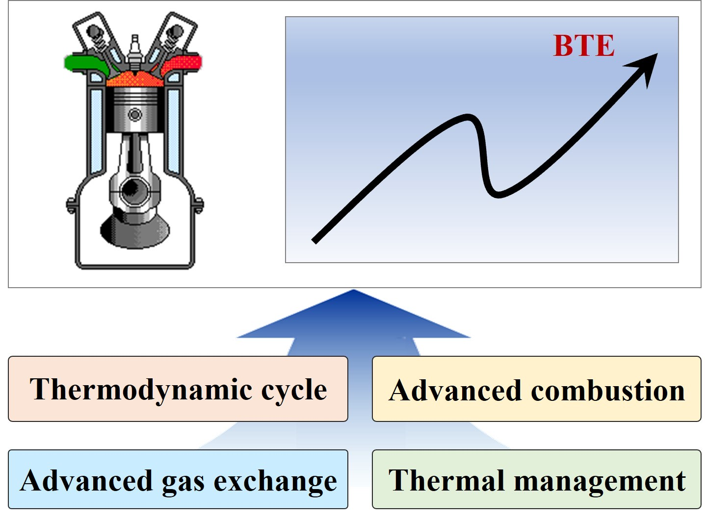
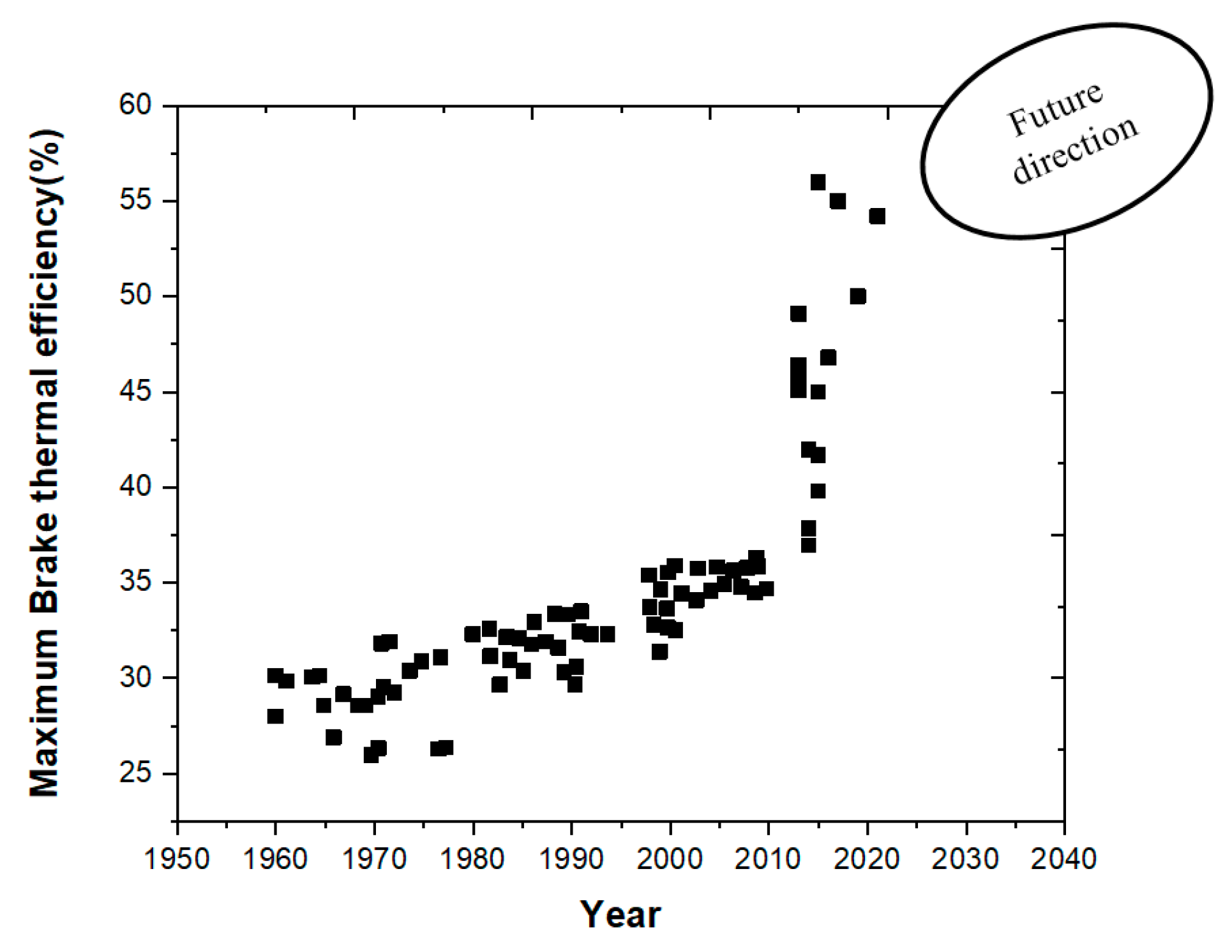
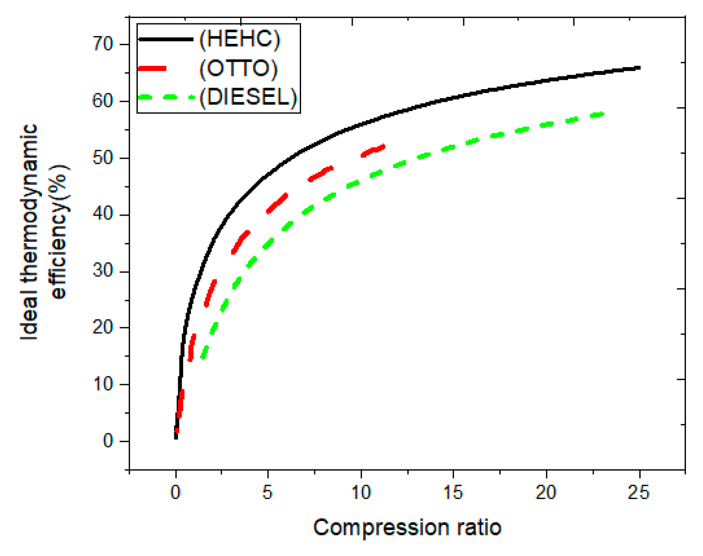
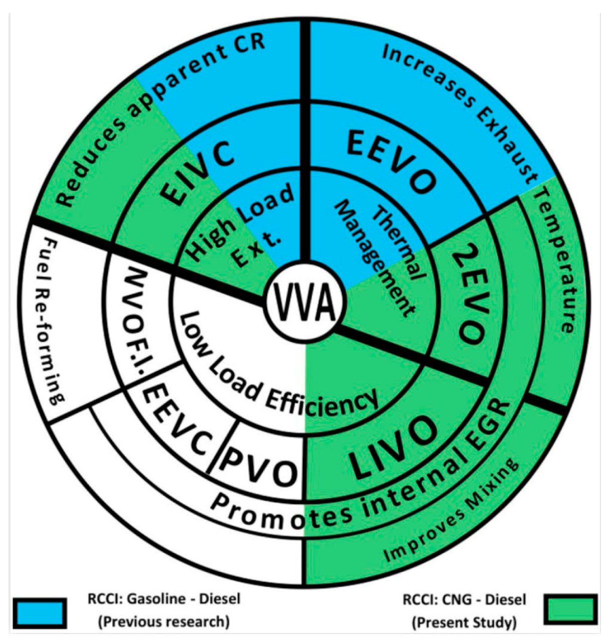
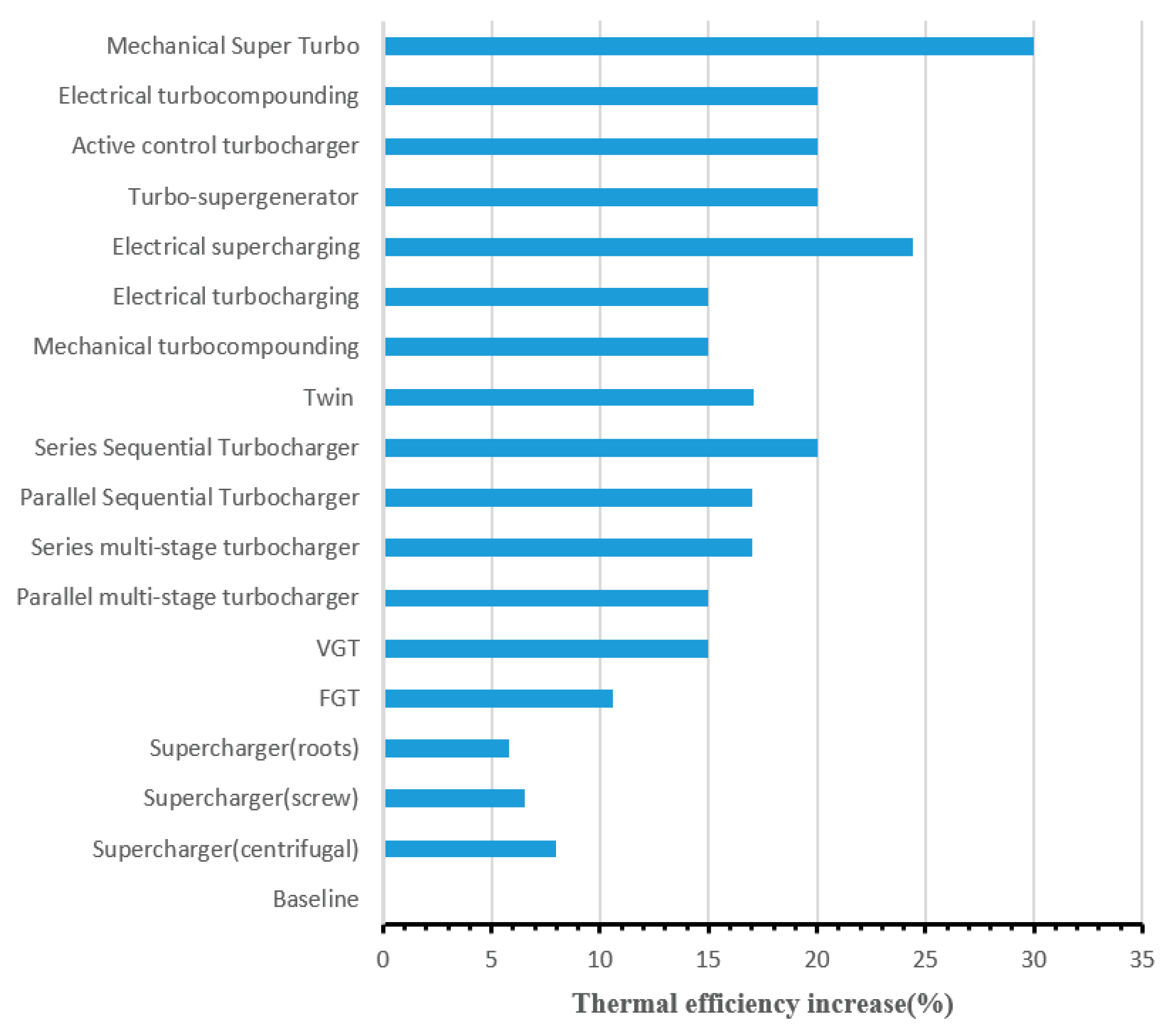
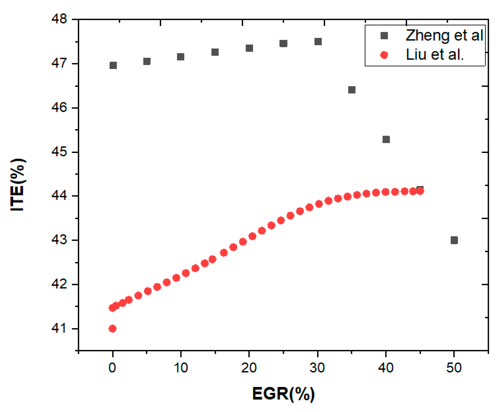
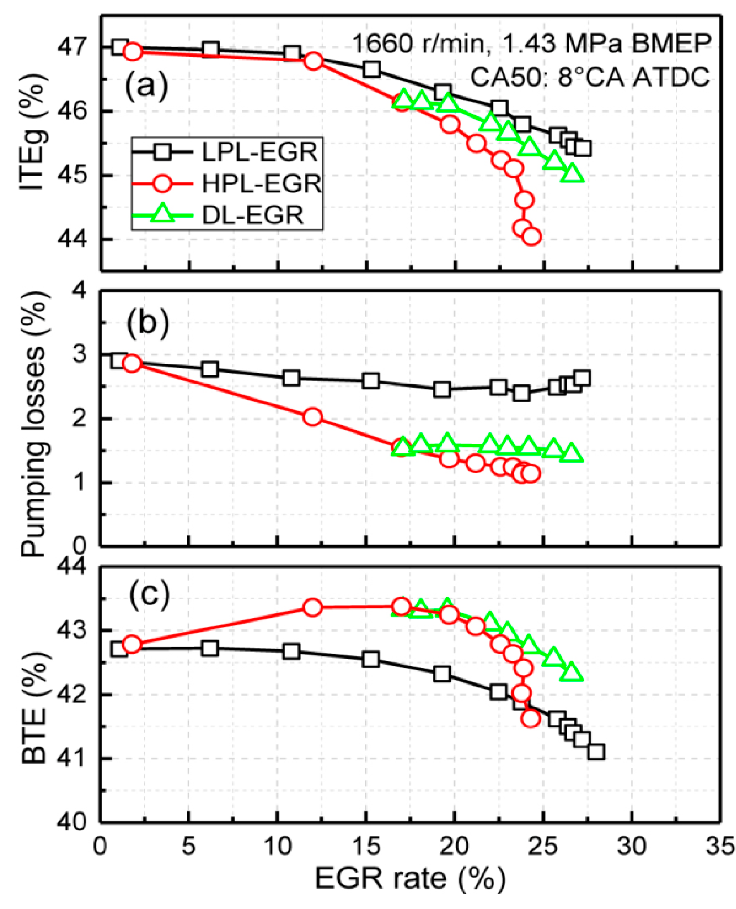
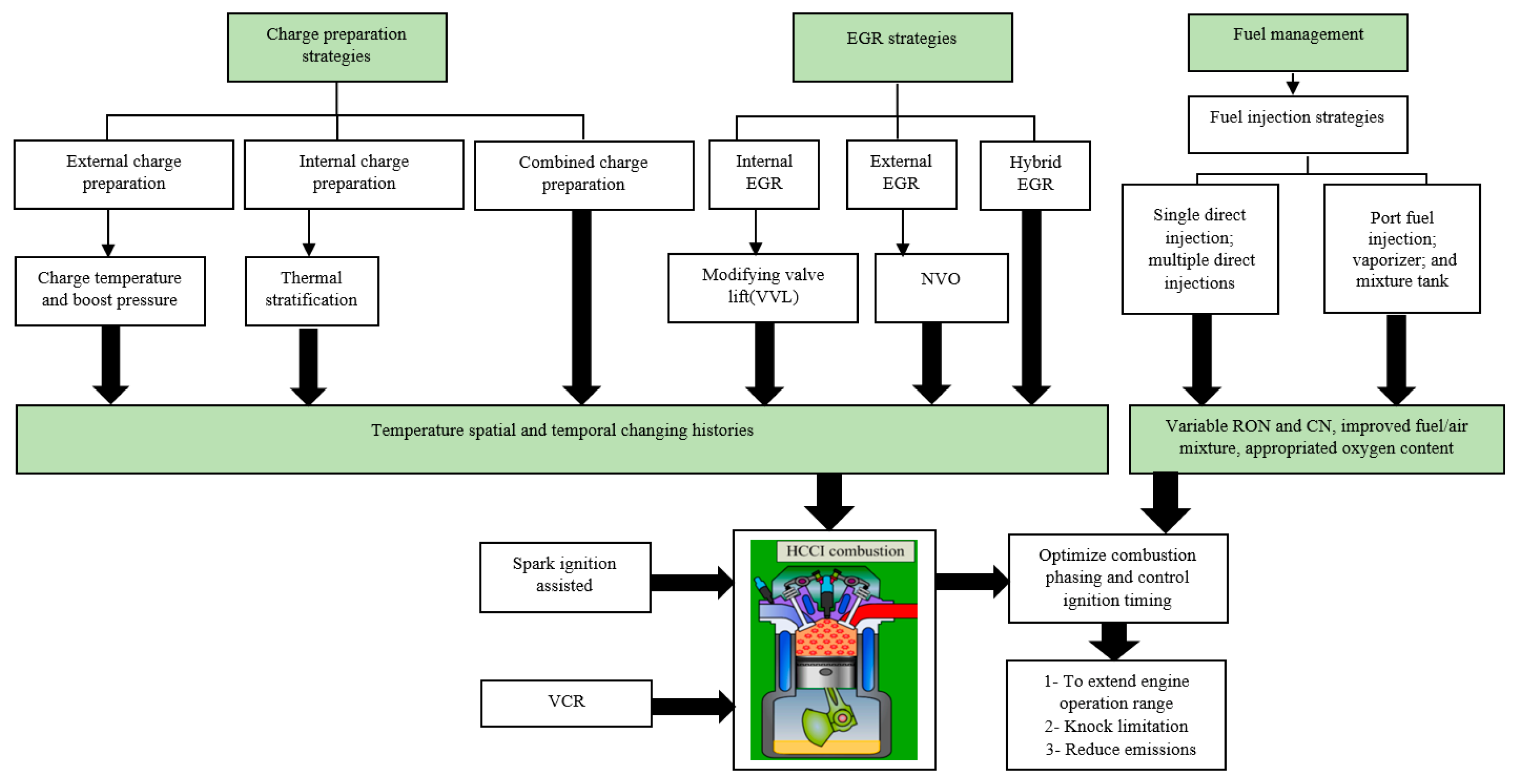
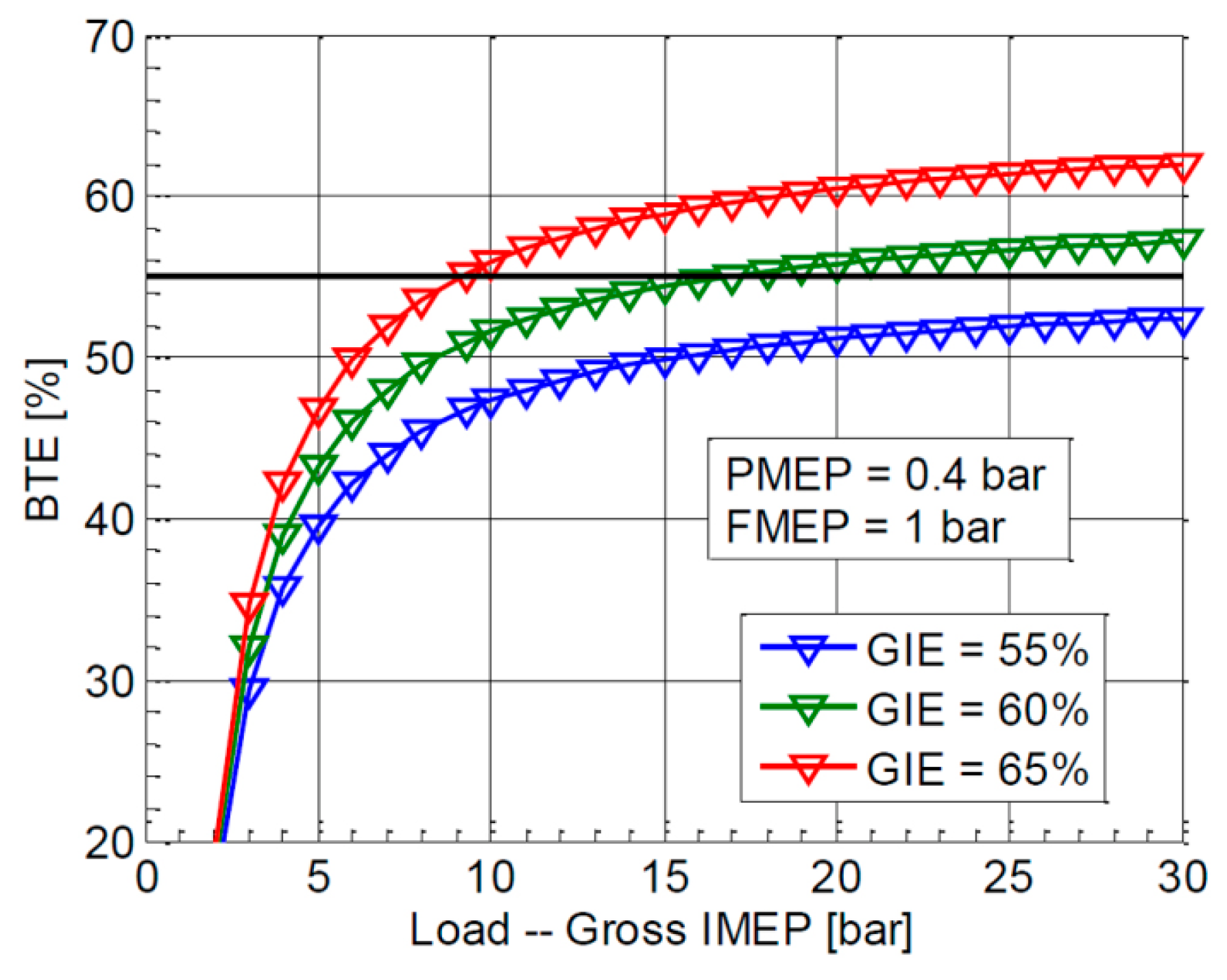
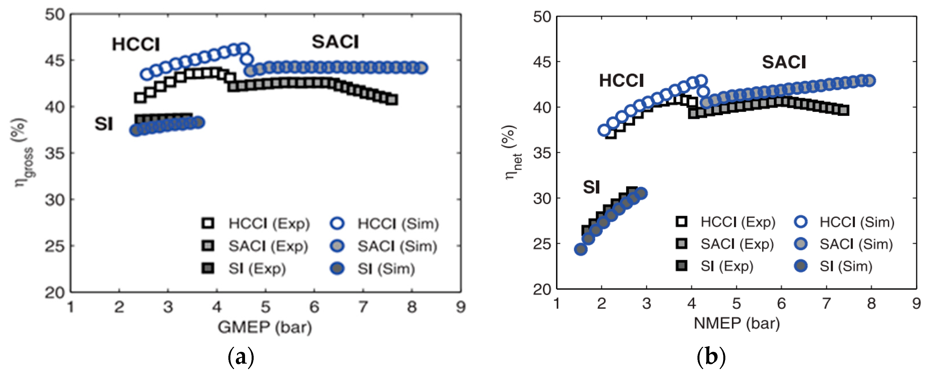
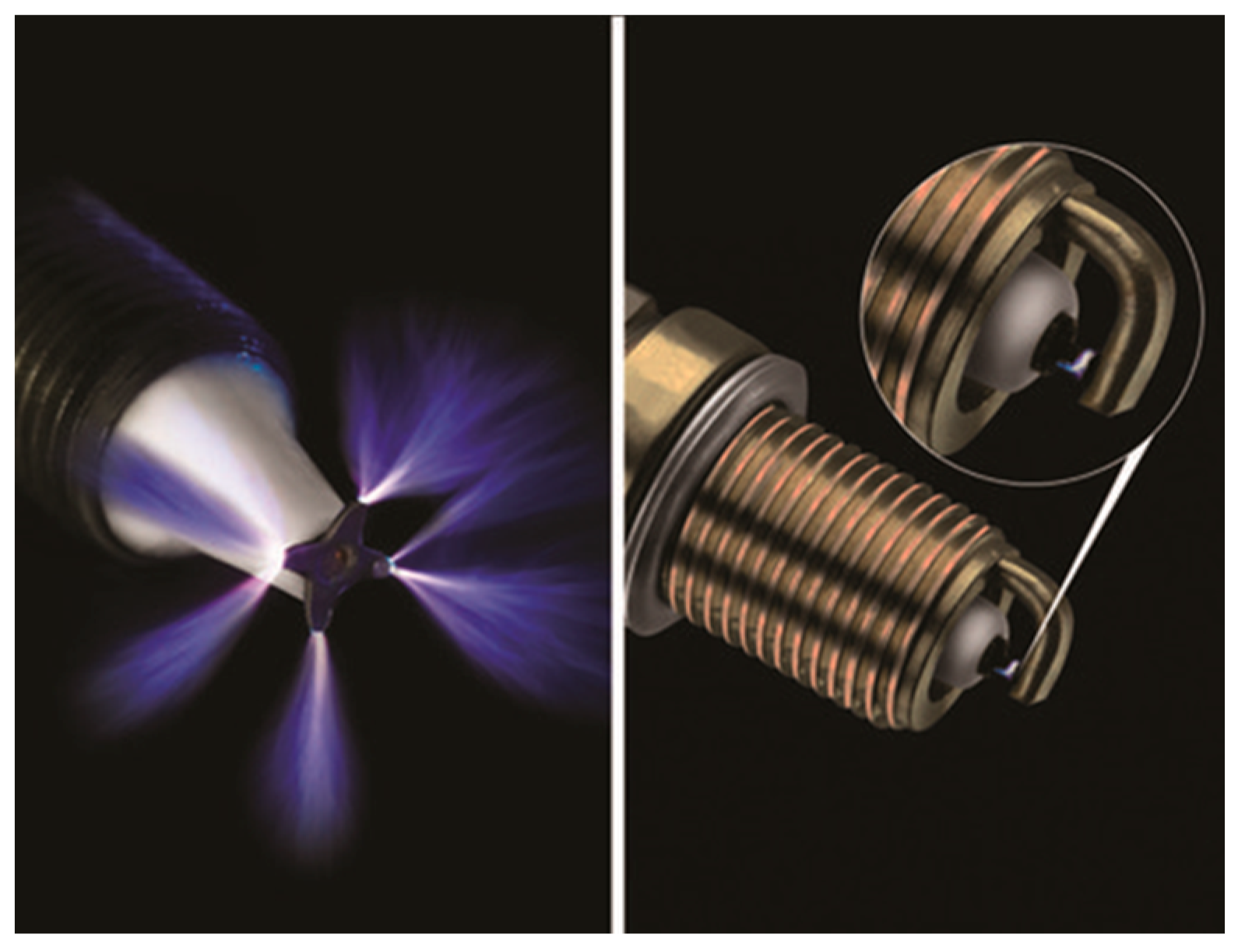
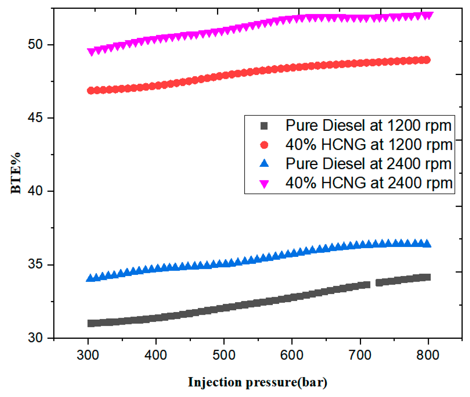
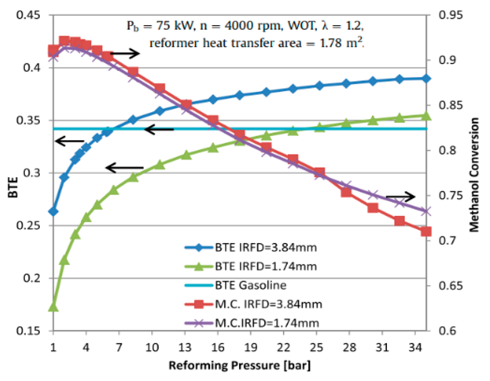
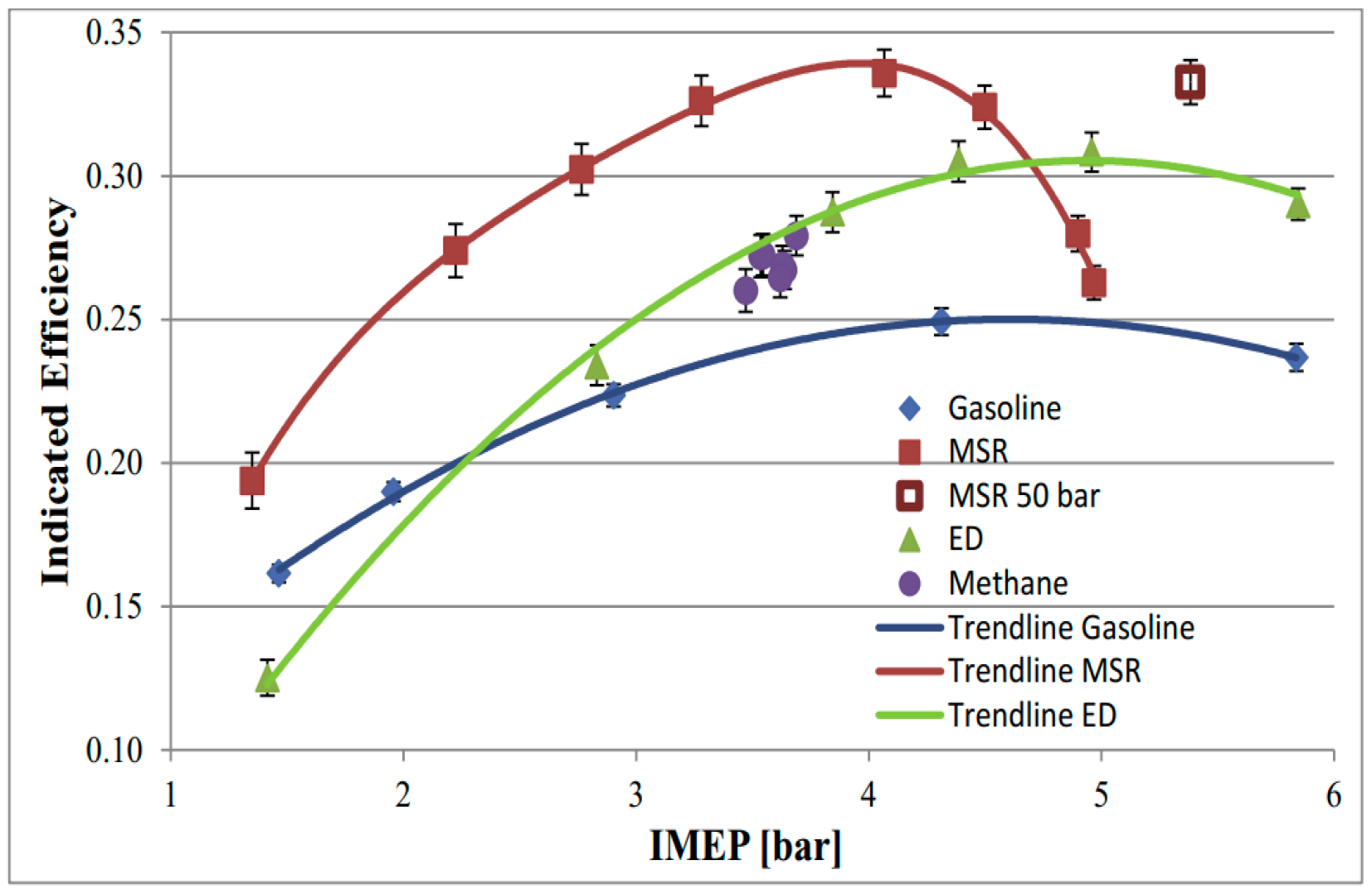
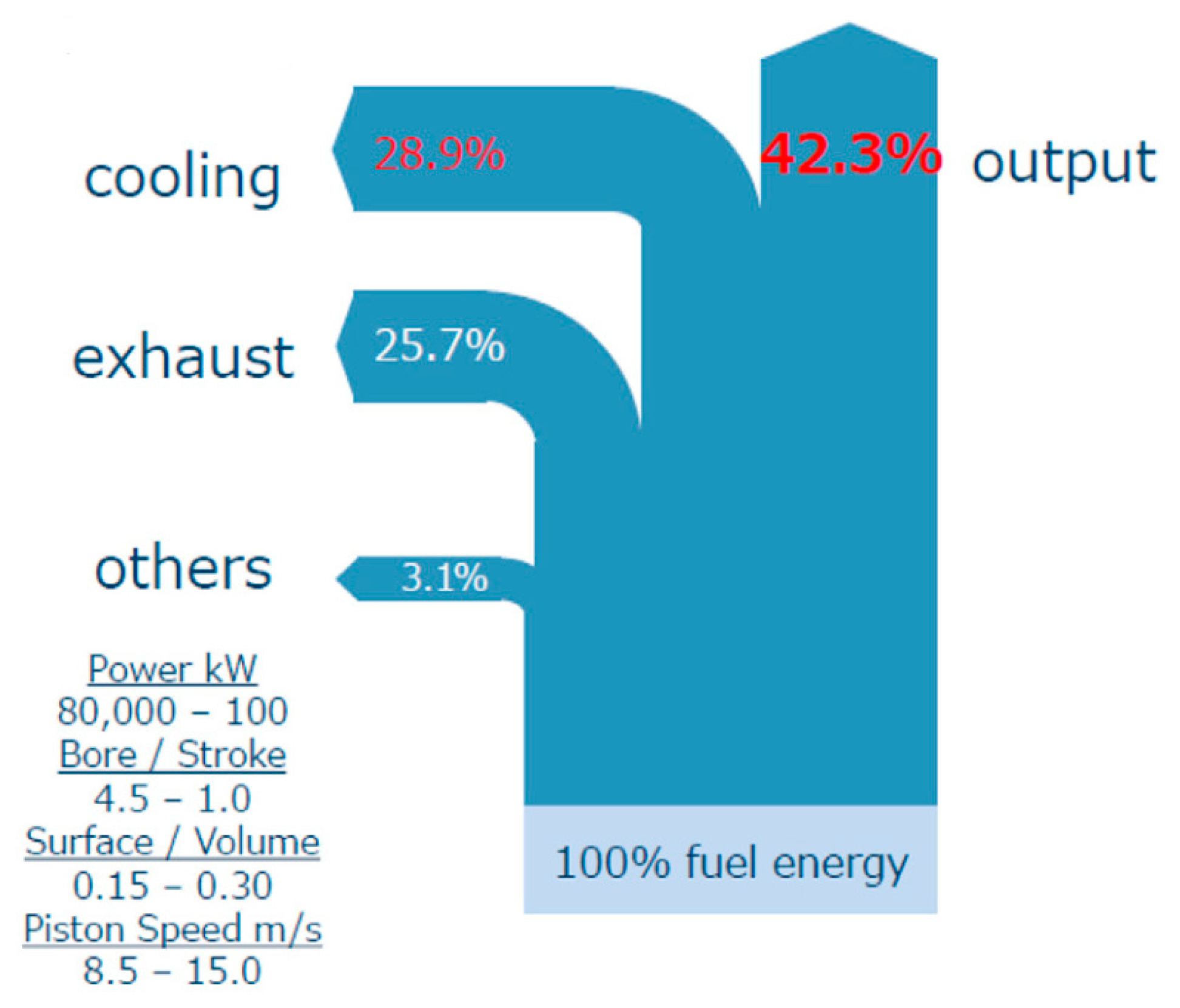
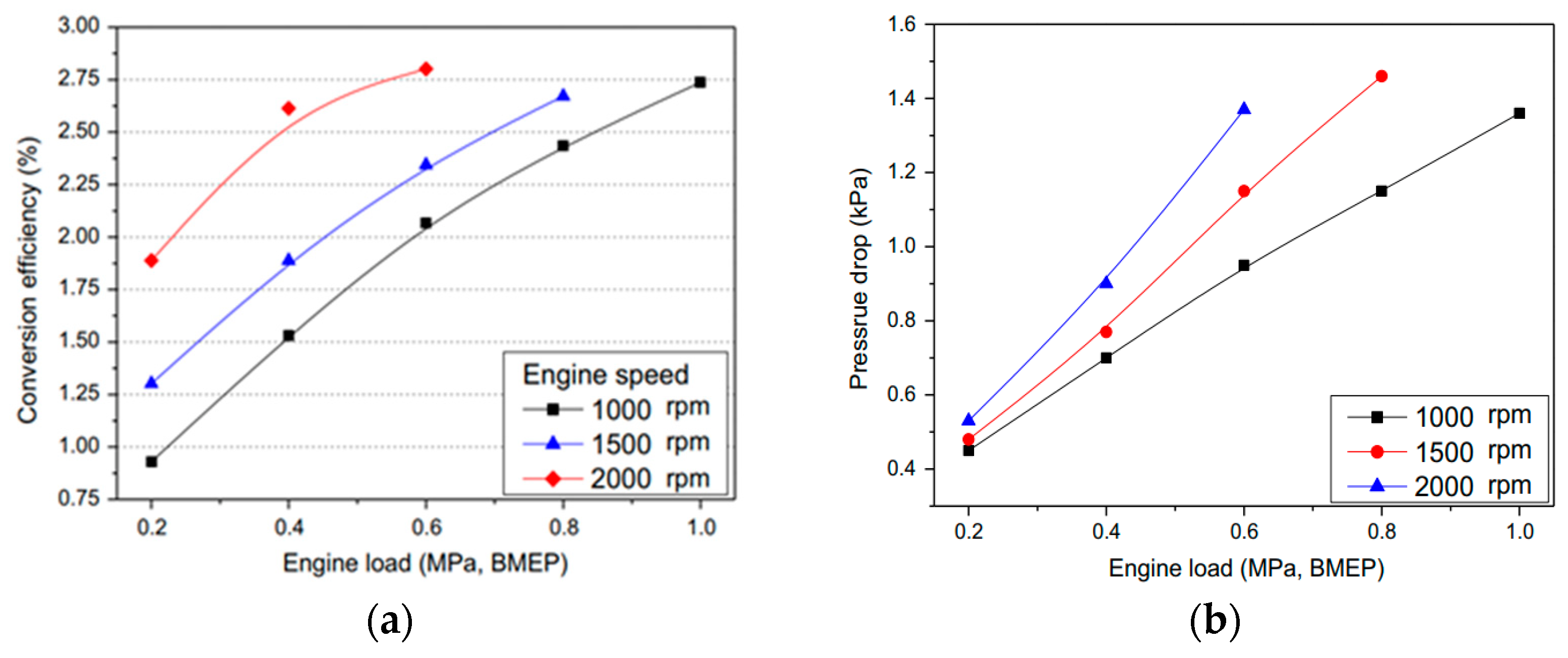
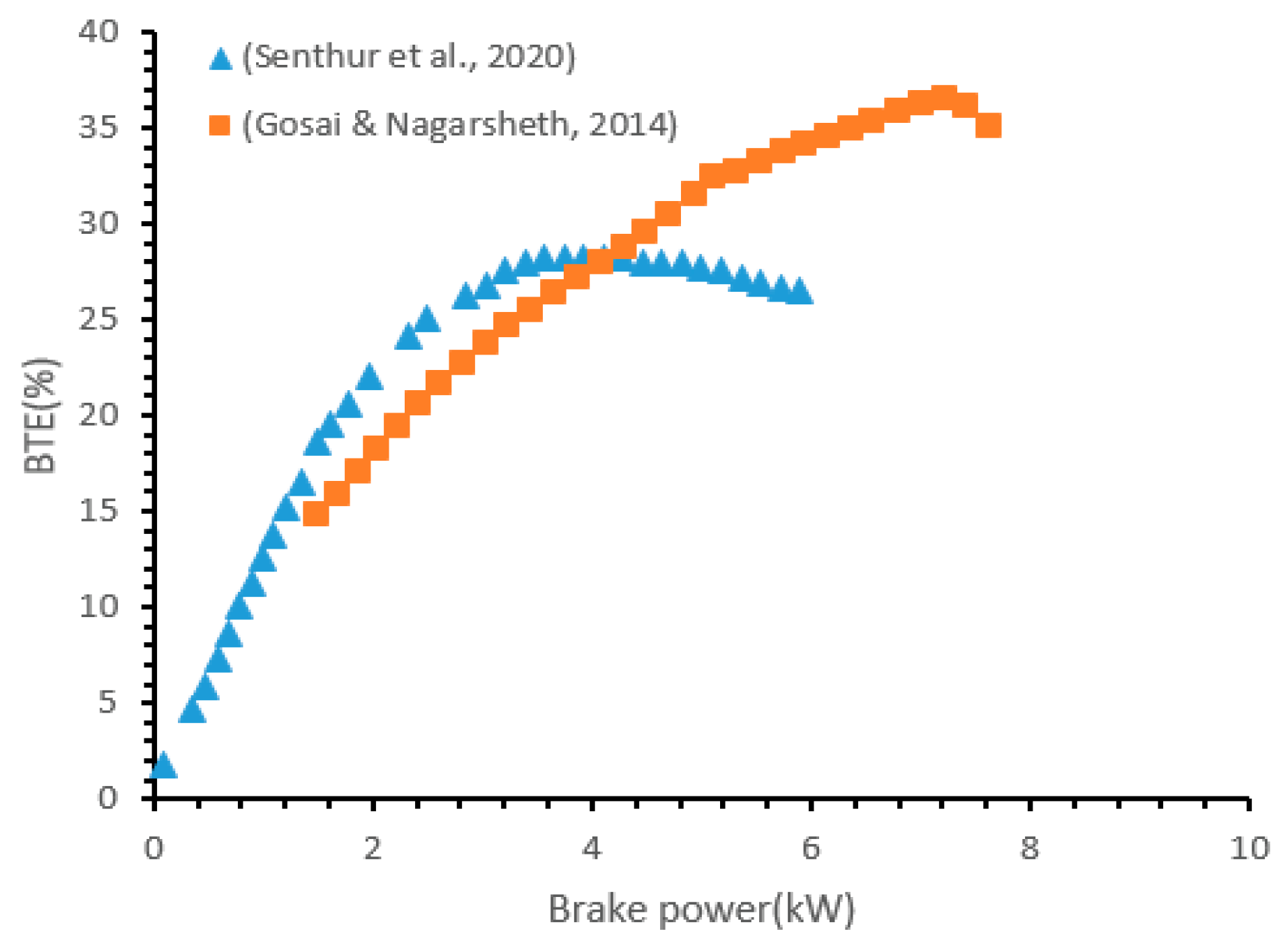
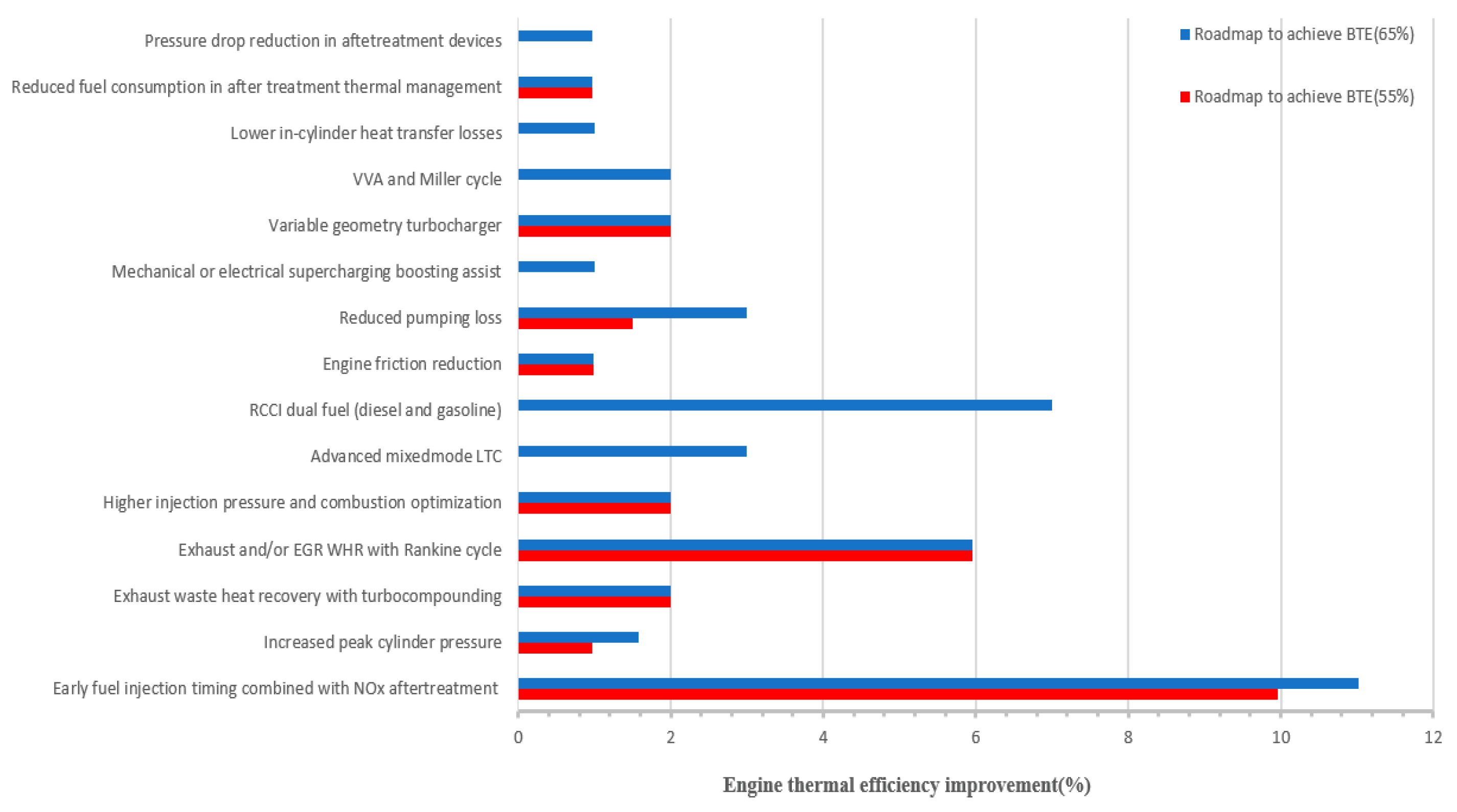
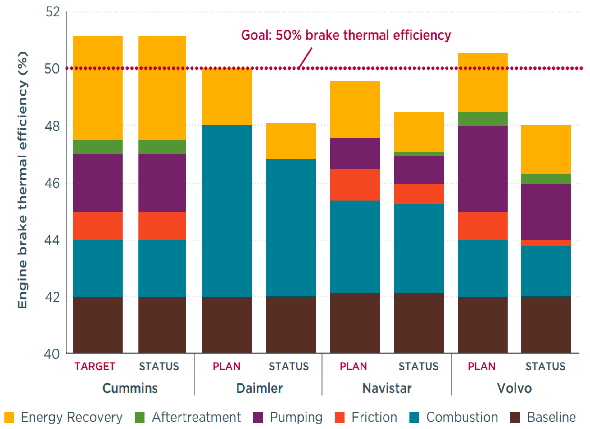
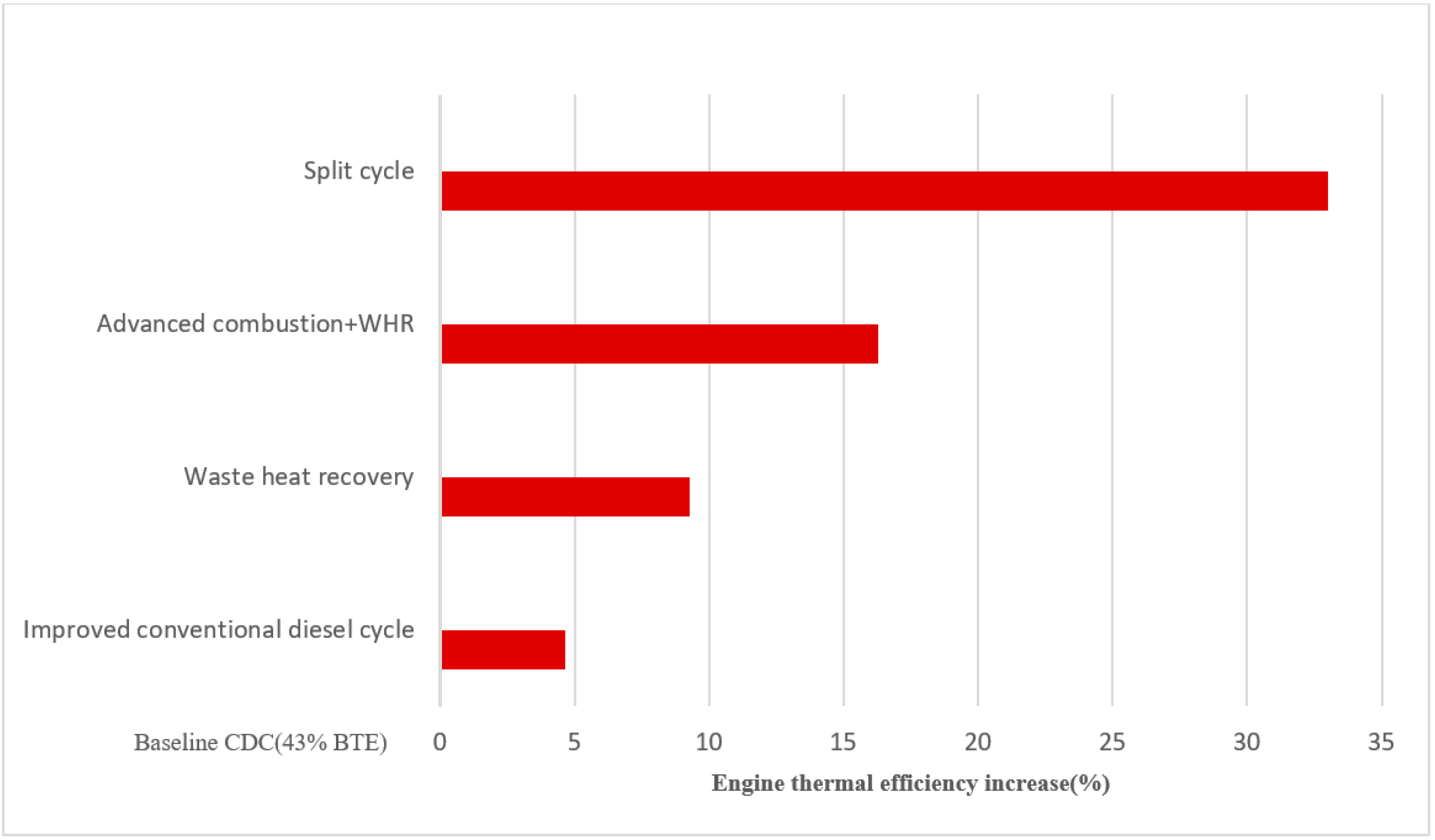
Figure 1. The target and historic CO2 emissions for light commercial vehicles [4].
Energies 15 06222 g001
Figure 2. The history of the brake thermal efficiency and future direction [9,16,17,18,20].
Energies 15 06222 g002
Figure 3. Ideal thermodynamic efficiency of high-efficiency hybrid cycle engine (HEHC), Otto, and diesel cycles [34].
Energies 15 06222 g003
Figure 4. Principle and category of the VVA strategies in internal combustion engines [72].
Energies 15 06222 g004
Figure 5. Comparisons between flexible two-stage and single-stage turbocharging [95].
Energies 15 06222 g005
Figure 6. Effect of various types of boosting systems on brake thermal efficiency [40,105].
Energies 15 06222 g006
Figure 7. The effect of EGR rate on brake thermal efficiency of diesel engines [116,117].
Energies 15 06222 g007
Figure 8. Combustion efficiency and torque at different EGR rates and excess air ratios [122].
Energies 15 06222 g008
Figure 9. (a) Indicated thermal efficiency, (b) pumping losses, and (c) brake thermal efficiency at different EGR ratios [128].
Energies 15 06222 g009
Figure 10. Schematic diagram of effective techniques used to control combustion phasing and ignition timing of HCCI engines [135,163].
Energies 15 06222 g010
Figure 11. BTE as a function of IMEPg and gross thermal efficiency(GTE) (GIE: gross indicated efficiency synonymous to GTE) [16].
Energies 15 06222 g011
Figure 12. Comparison of simulation and experimental gross and net thermal efficiency vs. load (a) Gross indicated thermal efficiency (GIE) (b) Net indicated thermal efficiency (ITEnet) [225].
Energies 15 06222 g012
Figure 13. Difference between ACIS (left) and conventional spark plug (right) [419].
Energies 15 06222 g013
Figure 14. Schematic representation of pre-chamber [261].
Energies 15 06222 g014
Figure 15. Illustrates the BTE under various injection pressures [277].
Energies 15 06222 g015
Figure 16. Relationship of methanol conversion and BTE on reforming pressure [286].
Energies 15 06222 g016
Figure 17. ITE at various load engines at 2800 rpm [288].
Energies 15 06222 g017
Figure 18. Energy distribution of a diesel engine [425].
Energies 15 06222 g018
Figure 19. (a) Conversion efficiency and (b) pressure drop across the TEG at different engine loads and engine speeds [397].
Energies 15 06222 g019
Figure 20. Brake thermal efficiency vs. brake power for different fuels in the LHR engines [413,414].
Energies 15 06222 g020
Figure 21. Thermal engine efficiency improvement technologies of diesel engines [6].
Energies 15 06222 g021
Figure 22. Brake thermal efficiency targets for super-trucks [378].
Energies 15 06222 g022
Figure 23. Potential increase in brake thermal efficiency of various engine technologies [7,20].
Energies 15 06222 g023
Table 1. Section presents the way in which the review is organized.
Research AspectsPaper TypeNumbersReference Order
Thermodynamic CyclesReview3[21,22,23]
Research12[10,24,25,26,27,28,29,30,31,32,33,34,35,36]
Advanced gas exchangeReview7[37,38,39,40,41,42,43]
Research87[44,45,46,47,48,49,50,51,52,53,54,55,56,57,58,59,60,61,62,63,64,65,66,67,68,69,70,71,72,73,74,75,76,77,78,79,80,81,82,83,84,85,86,87,88,89,90,91,92,93,94,95,96,97,98,99,100,101,102,103,104,105,106,107,108,109,110,111,112,113,114,115,116,117,118,119,120,121,122,123,124,125,126,127,128,129,130,131,132,133]
Advanced combustionReview18[43,134,135,136,137,138,139,140,141,142,143,144,145,146,147,148,149]
Research176[150,151,152,153,154,155,156,157,158,159,160,161,162,163,164,165,166,167,168,169,170,171,172,173,174,175,176,177,178,179,180,181,182,183,184,185,186,187,188,189,190,191,192,193,194,195,196,197,198,199,200,201,202,203,204,205,206,207,208,209,210,211,212,213,214,215,216,217,218,219,220,221,222,223,224,225,226,227,228,229,230,231,232,233,234,235,236,237,238,239,240,241,242,243,244,245,246,247,248,249,250,251,252,253,254,255,256,257,258,259,260,261,262,263,264,265,266,267,268,269,270,271,272,273,274,275,276,277,278,279,280,281,282,283,284,285,286,287,288,289,290,291,292,293,294,295,296,297,298,299,300,301,302,303,304,305,306,307,308,309,310,311,312,313,314,315,316,317,318,319,320,321,322,323,324,325,326,327,328,329,330,331,332,333,334,335,336,337,338]
Thermal managementReview11[6,339,340,341,342,343,344,345,346,347,348,349]
Research63[20,350,351,352,353,354,355,356,357,358,359,360,361,362,363,364,365,366,367,368,369,370,371,372,373,374,375,376,377,378,379,380,381,382,383,384,385,386,387,388,389,390,391,392,393,394,395,396,397,398,399,400,401,402,403,404,405,406,407,408,409,410,411,412,413,414,415,416,417]
Table 2. The benefits of various valve systems for fuel economy [37].
Refs.ModelType of SystemFuel Economy
GeneralHVVT3–5%
BMW Double VanosHVVT<10%
[73]GeneralEVVT3–5%
[73]Audi AVS systemDVVL<7%
[74]GM intake valve lift DVVL<4%
Honda i-VTECDVVL + VVT <13%
[73]BMW ValvetronicCVVL + VVT <10%
Toyota ValvematicCVVL + VVT <6%
Fiat MultiAirLMVVA <10%
[75]GeneralEVVT + VVL<20%
[75]GeneralCamless VVA <25%
Table 3. Review and comparison between three different advanced combustion technologies [178].
Primary Reference Fuel Pump Fuels
Fixed ConditionHCCIPPCRCCIFixed ConditionsPPCRCCI
GIE (%)47.145.647.5GIE (%)46.946.1
NOx (g/kg-fuel)0.050.010.04NOx (g/kg-fuel)0.150.05
COV of IMEP (%)2.62.52.6COV of IMEP (%)2.52.1
Comb. Efficiency (%)92.893.191.5Comb. Efficiency (%)93.793.2
PPRR (bar/deg)14165.8PPRR (bar/deg)16.411.7
CA 50   ± σ 50   aTDC 3.5 ± 0.52.5 ± 0.32.2 ± 0.5 CA 50   ± σ 50   aTDC 3.2 ± 0.42.7 ± 0.9
Table 4. Comparison between dual-loop ORC and CCE-ORC systems [376].
ParametersCCE-ORC SystemDual-Loop ORC System
Engine speed (rpm)14001400
Net power output (W)29,00026,800
Total thermal efficiency (%)11.6711.39
Total exergy efficiency (%)38.6235.72
Heat transfer rate of the high-temperature evaporator (kW/°C)2.1421.790
Heat transfer rate of the low-temperature evaporator (kW/°C)8.4458.323
Heat transfer rate of the condenser (kW/°C)8.2908.151
Heat transfer rate of intermediate heat exchanger (kW/°C) 8.803
The heat energy of a high-temperature evaporator (W)133,400120,000
The heat energy of a high-temperature evaporator (W)115,200115,200
The heat energy of the condenser 219,700208,400
The heat energy of the intermediate heat exchanger 102,700
High evaporating temperature (K)488488
Low evaporating temperature (K) 343.95345.45
HT evaporating pressure (bar)32.92532.925
LT evaporating pressure (bar)1.9566.486
HT turbine pressure ratio16.811.8
LT turbine pressure ratio1.7183
HT turbine mass flow rate (kg/min)12.613.38
LT turbine mass flow rate (kg/min)29.2864.98
Table 5. Characteristics of thermoelectric generation [397].
Speed
(rpm)
Load (BMEP)
(MPa)
Mass Flow Rate
(kg/h)
Exhaust Gas Inlet Temperature
(K)
Conversion Efficiency
(%)
10000.264.6414.90.9
0.468.94731.5
0.674.2533.82.1
0.881.5585.42.4
1.088.4632.62.7
15000.280.4447.91.3
0.494.6509.791.9
0.6108.3562.52.3
0.81246082.7
20000.2121.8489.61.9
0.4147.8550.82.6
0.6174.2597.12.8
Publisher’s Note: MDPI stays neutral with regard to jurisdictional claims in published maps and institutional affiliations.

