1. Introduction
The signing of the Paris Agreement has reminded people about the widespread concerns about climate risks and the negative impacts of fossil fuels. The agreement sets a long-term global goal to limit the temperature increase to 1.5 °C by phasing out inefficient fossil fuels [
1]. In this context, clean fuels such as methanol [
2], syngas [
3], hydrogen [
4], and biofuels [
5,
6] are receiving increasing attention. However, most alternative fuel vehicles have not yet been widely accepted by the market, constrained by fuel technology, fueling station availability, purchase price, operational cost, fuel efficiency, mileage, and maintenance cost [
7].
Compared with traditional gasoline and diesel, alternative fuels commonly have lower hydrogen-carbon ratios and combustion temperatures, resulting in CO
2, NO
x, and PM emissions advantages. However, the slow promotion of alternative fuels implies inherent defects, which increase the application cost in most cases. For example, methanol’s high calorific value, fast flame speed, and high knock resistance significantly improve engine efficiency. Still, its condensation at low temperatures and corrosiveness at high temperatures make it difficult to use as an engine fuel alone. Complex schemes such as conventional Spark Ignition (SI) engines with methanol as octane boosters or gasoline-methanol flex-fuel engines are more promising for light-duty applications. For heavy-duty applications, diesel-methanol dual-fuel Compression Ignition (CI) engines are widespread on large ships [
8], but at the expense of higher manufacturing costs and reliability risks. Similarly, hydrogen suffers from the challenges of storage safety and hydrogen embrittlement, limiting its application as an independent engine fuel [
9]. In contrast, Natural Gas (NG) [
10] stands out as the most promising alternative fuel for engines because of its availability, safety, and other superiority, such as low corrosiveness.
To further investigate the emission reduction capacity of NG, mechanical scientists and engineers keep developing progressive engine techniques. Premixed Charge Compression Ignition (PCCI) [
11,
12], Reactivity Controlled Compression Ignition (RCCI) [
13], and Homogeneous Charge Compression Ignition (HCCI) [
14,
15] not only significantly improve thermal efficiency and reduce CO
2 emissions [
16,
17] but also provide excellent fuel adaptability and flexibility. However, the uncontrollable combustion of HCCI, the limited load area of PPCI, and the high HC and CO emissions of RCCI need additional attention. Lean burn [
18] and Exhaust Gas Recirculation (EGR) [
19] technologies offer distinct advantages in suppressing pollutants and knocking. But the low-temperature methane catalysis challenge of lean burn mode and the exhaust pulse issue of EGR should be addressed appropriately. In addition, hydrogenated NG [
20] and NG-diesel dual-fuel [
21] technologies improve ignition stability by increasing the initial number of combustion nuclei, solving the inherent problem of slow NG flame propagation [
22].
Nevertheless, in the quest for advanced combustion technologies, contradictions among customers, manufacturers, and regulators are often overlooked [
23]. For customers, low prices and performance are the most substantial attributes. But the two attributes usually mean uncertainty of emissions controls, which regulators care about the most [
24]. Manufacturers must compromise between customer needs and society’s goals and carefully consider the most valuable technologies for mature production lines. For heavy vehicles, SI NG engines retrofitted from the traditional diesel scheme [
25] are the first to complete commercial promotion and receive extensive attention from the industry [
26].
Limited by the manufacturing cost and product universality requirements, heavy-duty NG engines prefer to follow the swirl intake design of diesel engines. But during compression, the swirl flow’s Turbulent Kinetic Energy (TKE) becomes insufficient, exacerbating NG’s inherent slow combustion problem. To continuously improve engine performance, developing intake, exhaust, and combustion systems that match the NG premixed combustion mode is a valuable mid-term goal. Among them, the improvement of the intake port should be completed first to enhance the scavenging, ignition, and combustion performance. The objective can be achieved in several ways, depending on design parameters and numerical models. As the basis of modern numerical simulation, the 1D method is still one of the most potent tools for intake system research. Kesgin [
27] established a 1D model of a stationary NG engine, optimizing the valve timing, valve diameter, valve lift profile, exhaust manifold diameter, inlet/exhaust pipe length, and pipe junction geometry. The improved intake system increased the thermal efficiency of the engine. In contrast, multi-objective optimization combining 1D fluid dynamics models [
28], machine learning [
29], and search algorithms [
30,
31] is more advanced. It should be noted, however, that the more empirical approach is not conducive to revealing the nature of physical phenomena.
On the other hand, with the improvement of computational efficiency, 3D simulation has gradually become popular. Basha et al. [
32] reviewed Computational Fluid Dynamics (CFD) simulations of in-cylinder flow, turbulence, and spray characteristics, comparing the accuracy, efficiency, and availability of different models and codes. Jemni et al. [
33] performed geometric optimization on the intake system of a heavy-duty liquefied petroleum gas engine based on 3D CFD code, significantly improving brake power, brake torque, and brake thermal efficiency. Wahono et al. [
34] compared the effects of four intake port schemes on the flow organization, including various combinations of helical and tangential structures. They found that the flow coefficient and TKE of the tangential intake port were better, contributing to the formation of a homogeneous air-fuel mixture. The reviewed investigations supply essential understandings of intake systems for NG engines. However, comprehensive work about flow, combustion, and emissions in the cylinder is relatively insufficient, particularly for heavy SI NG engines.
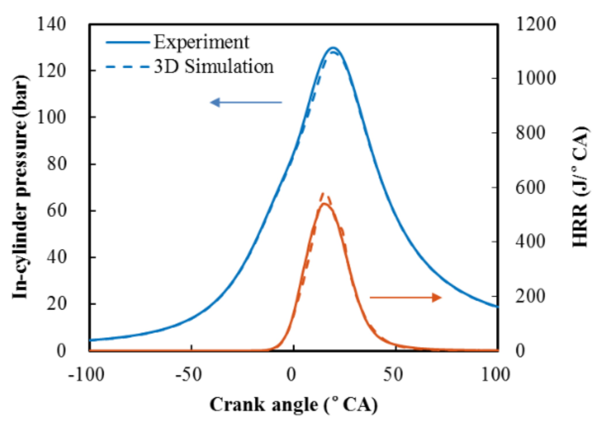
Therefore, the present research strives to improve engine performance and emissions by modifying the intake port structure. Based on a commercial SI NG engine, this study proposes a Mixed-Flow Intake Port (MFIP) structure to explore performance boundaries by improving the large-scale flow and TKE. The flow, combustion, and emission characteristics of MFIP and Swirl Intake Port (SIP) were compared through multidimensional numerical simulation. A novel optimized chemical kinetic model [
35] is applied in the 3D simulation with the calculation time cost saved by 30% while high accuracy is maintained. The simulation results are in good agreement with the bench test. In conclusion, this study revealed the intake characteristics and effects of 10~15 L heavy-duty SI NG engines, laying a theoretical foundation for the future application of strong tumble flow intake schemes.
3. Results and Discussion
3.1. Influence of Intake Port on In-Cylinder Flow
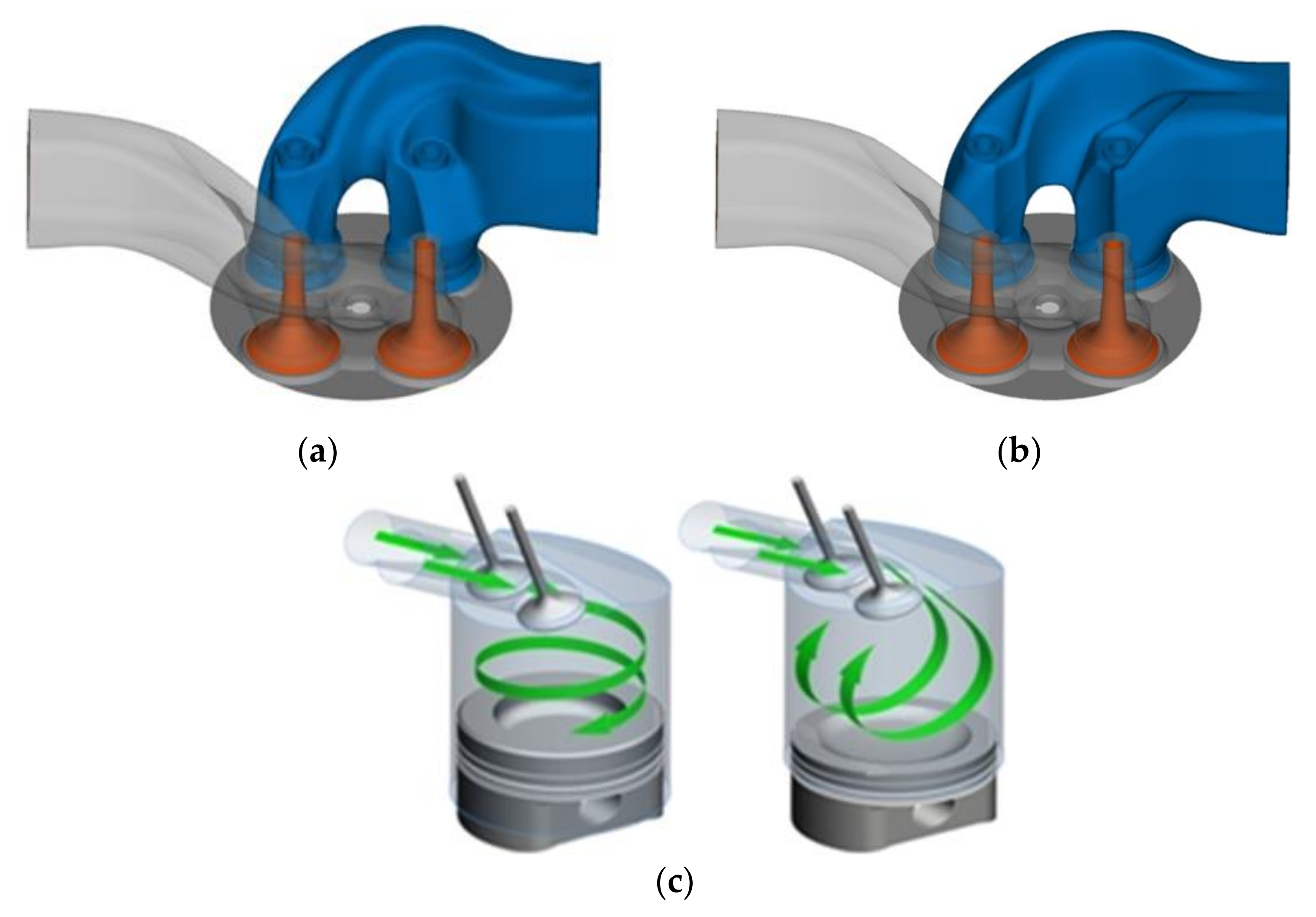
The intake port structure determines the large-scale in-cylinder flow and turbulent kinetic energy, further affecting the engine performance and emissions. The large-scale in-cylinder flow is characterized by swirl and tumble flow, parallel and perpendicular to the cylinder axis, as shown in
Figure 3c. Reasonable flow organization can increase in-cylinder TKE, strengthen heat and mass transfer, and improve the inherent defects of NG engines, including slow flame speed and harmful cycle variation. In this paper, the intake port of the SI NG engine is modified, and the intake tumble flow is enhanced by changing the helical port to a tangential port, as shown in
Figure 3.
The CFD simulation was conducted to reveal the difference in the in-cylinder flow of the two intake ports as the basis for the subsequent engine performance analysis.
Figure 4 compares the SIP and MFIP in Swirl Ratio (SR), Tumble Ratio (TR), and average TKE under the low-speed torque point of 1000 rpm, 2150 N·m. The term SR is defined by Equation (1), where
represents the engine shape factor,
represents the flow coefficient,
represents the dimensionless swirl,
and
represent the crank angle when the intake valve opens and closes. Moreover, the definition of TR is similar.
In the early stage of compression before 50° CA bTDC, the SR values of both intake ports remain almost constant. As the compression stroke progresses, the cylinder head and the piston top land are squeezed, the peripheral swirl flow moves inward, and the in-cylinder SR rises rapidly. At the end of the compression, the swirl is broken by the vertical impact of the squish flow, decreasing the SR. Overall, the SR of MFIP is 32% lower than SIP, and the maximum SR is reduced from 1.57 to 1.07.
During the compression process, both the TR of MFIP and SIP presented a rising-falling trend. The reason is that as the piston moves upward, the in-cylinder volume decreases, and the airflow passively tumbles. When the in-cylinder volume declines to the critical point, the tumble flow begins to break up gradually under the action of extrusion and shearing to form small-scale turbulence, resulting in a decrease in the TR. Compared with SIP, the maximum in-cylinder TR of MFIP is increased from 0.20 to 0.94, an increase of 470%. In summary, the large-scale in-cylinder flow of the two intake ports differs obviously. The in-cylinder SR of MFIP decreases while the TR increases significantly.
By definition, TKE is determined by macroscopic kinetic energy and its variance. During the compression process, the tumble flow hits the piston straight, then breaks into smaller eddies, increasing the turbulence intensity. Therefore, the average TKE of MFIP keeps more heightened than SIP. At TDC, the TKE of MFIP is 25% more elevated. On the other hand, as the compression progresses, the turbulence dissipation increases with the flow complexity, resulting in a decrease in the average velocity, and the average TKE of both intake ports shows a downward trend.
3.2. Influence of Intake Port on Engine Performance
The large-scale flow of MFIP presents better organization, resulting in higher TKE, which helps improve the NG engine’s performance. In a combined bench test and CFD simulation, this paper quantitatively researches the influence of intake ports on engine performance.
Table 5 shows the typical operating points for intake port research, including the maximum power point, maximum torque point, typical operating point, and low-speed torque point of the engine. The results indicate that MFIP improves engine economy and stability, presenting more advantages than SIP.
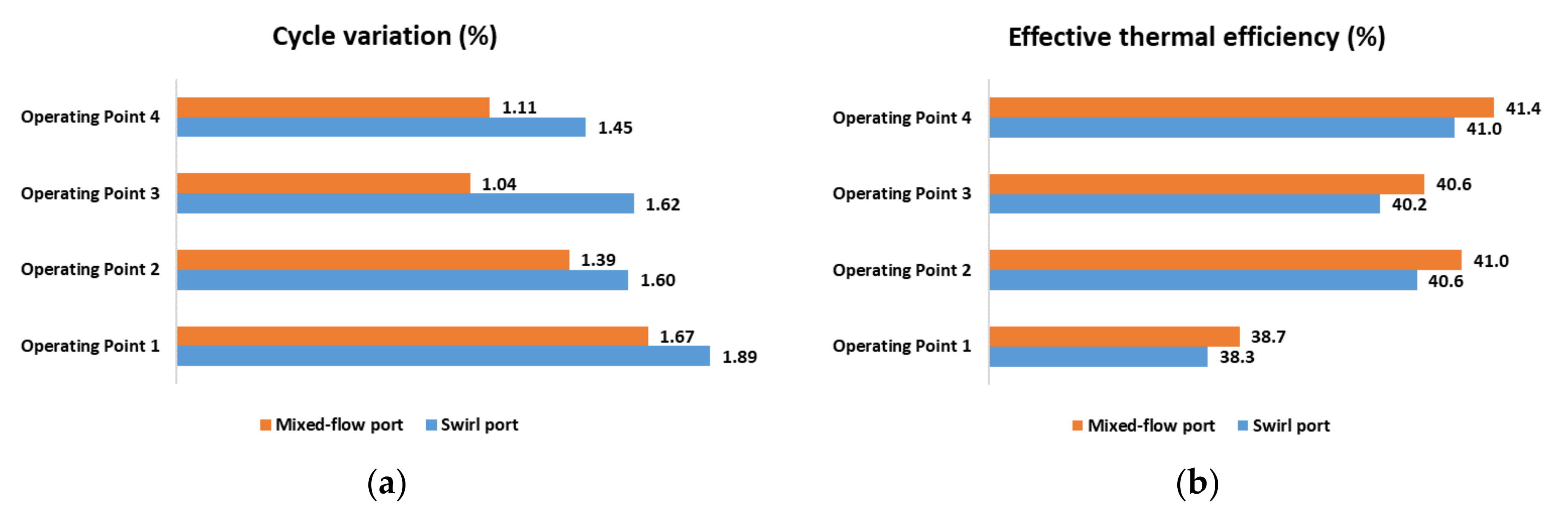
Based on bench test data,
Figure 5 compares SIP and MFIP in cycle variation and the effective thermal efficiency under different operating conditions. The term cycle variation, i.e., Coefficient of Variation, is defined by Equation (2), where
and
represent the mean and standard deviation of
cycle measurements, respectively.
As the speed of operating points 1, 2, and 4 gradually decreases, the cycle variation advantage of MFIP increases. Compared with SIP, the cycle variation of MFIP at operating point 4 decreased by 23.5%, while the decrease in operating point 1 was only 11.7%. The intake volume decreases with engine speed reduction, and MFIP becomes more critical to improving turbulence intensity. Therefore, the combustion duration of MFIP at low speeds is shorter, and the engine stability becomes stronger. Similarly, among operating points 2 and 3 at the same speed, point 3 with lower torque has a 35.8% cycle variation advantage. In addition, the economy of MFIP is 0.9~1.2% better than SIP, and the highest thermal efficiency reaches 41.4%.
This paper applies an optimized hybrid kinetic model based on stochastic gradient descent [
35]. Compared with the detailed reaction mechanism of natural gas, the computational cost for the optimized model is significantly reduced. The previous study has found that the accuracy of the optimized model has obvious advantages over the general simplified mechanism [
23]. Based on the CFD simulation,
Figure 6 compares the HRR and accumulated Heat Release (HR) of the two intake ports. The characteristic combustion parameters are shown in
Table 6. The results show that the ignition delay period (Pre-CA10) of MFIP is shortened, the combustion center (CA50) is advanced, whereas the combustion duration (CA10~CA90) is longer.
The ignition delay is usually detrimental and can be suppressed by enhancing spark energy and turbulence intensity. Because of the higher TKE of MFIP, the combustion nucleus develops faster, resulting in a decrease in ignition delay by 9%. In the early combustion stage (CA10~CA50), due to the high in-cylinder TKE, the flame front is extended by turbulence, which increases the flame propagation speed. Therefore, the early combustion stage of MFIP is shortened by approximately 11%. Meanwhile, the combustion center of MFIP is closer to TDC, improving thermal efficiency. However, in the late combustion stage (CA50~CA90), the breaking process of the tumble flows almost ends. In contrast, the swirl flow is disturbed by the squish impact, which eventually leads to a decrease in the combustion speed of MFIP and a 37% extension of the late combustion stage.
3.3. Influence of Intake Port on Engine Emissions
The pollutants emitted by NG engines mainly fall into three categories: NOx, CO, and HC (unburned and partially burned hydrocarbons). Pollutant emission levels depend on the interaction between the in-cylinder physical and chemical processes, commonly dominated by chemical kinetics and deviating from chemical equilibriums. The MFIP has more homogeneous air-fuel mixing and faster flame propagation than SIP, so the CO emissions are significantly reduced, the NOx emissions are increased, and the HC emissions are roughly the same.
The comparison of NO
x, CO, and HC of MFIP and SIP under the two operating conditions is shown in
Figure 7. Under the two operating conditions, the NO
x emissions of MFIP are 0.62 and 0.58 g/kWh higher than SIP, respectively, with a relative increase of 11.8% and 8.4%. In general, thermal NO
x is the primary source of nitrogen oxides in NG engines. Its generation follows the Zeldovich mechanisms [
36], which are sensitive to temperature and oxidizing atmosphere. On the one hand, MFIP has fast flame propagation and high temperature in the cylinder, promoting thermal NO
x generation. On the other hand, the engine adopts the stoichiometric combustion mode, so the influence of O
2 concentration seems relatively negligible.
Under the two operating conditions, the CO emissions of MFIP are 1.03 and 1.15 g/kWh lower than SIP, with a relative reduction of 10.9% and 9.9%. Previous studies have suggested that CO emissions are affected by both chemical equilibrium and reaction kinetics [
37]. MFIP promotes the formation of a homogeneous air-fuel mixture, increases the concentration of OH, H, and O radicals, and suppresses the generation of CO. At the same time, MFIP also increases the exhaust temperature and promotes the chemical kinetics of CO oxidation, further reducing CO emissions.
The HC emissions of the two intake ports were approximately similar. While the emission concentration of MFIP is slightly taller, 3.4% and 2.4%, than SIP. The combustion chamber crevice contributes the most to HC emissions, and its sensitivity is strongly affected by the small-scale flow and flame boundary [
38]. The combustion center of MFIP is closer to TDC, which increases the in-cylinder pressure, thereby increasing the unburned mixture in the combustion chamber crevice.
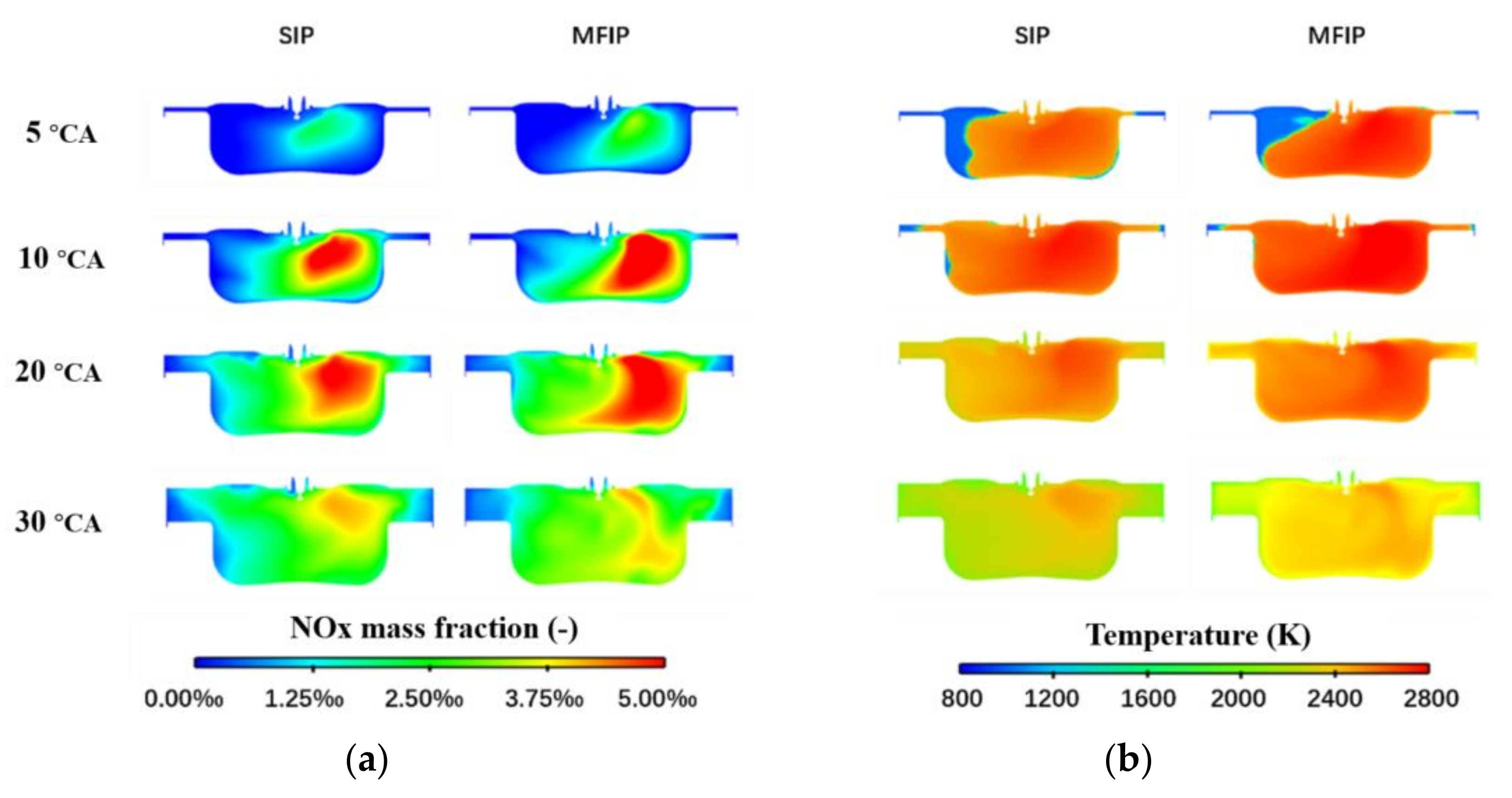
Figure 8 compares the intake ports in NO
x mass fractions and in-cylinder temperatures. The NO
x concentration is highly dependent on the in-cylinder temperature with an inevitable delay. In the range of 5~30° CA aTDC, affected by the flame propagation process, the exhaust side temperature is higher, resulting in the local enrichment of NO
x. The in-cylinder temperature peaked at 10° CA aTDC, while NO
x generation was kinetically controlled by the reaction of N
2 with O radicals [
39]. Hence the maximum NO
x concentration appeared later at 20° CA aTDC. Due to the high TKE and combustion temperature of MFIP and the longer late combustion stage, its NO
x mass fraction is more increased than SIP.
4. Conclusions
A mixed-flow intake port was designed in this work based on a heavy-duty natural gas engine. The influence of the structure on the in-cylinder large-scale flow and turbulent kinetic energy was analyzed via the CFD method, and the bench test confirmed the superior performance of the mixed-flow intake port. Further temperature distribution and NOx mass fraction were analyzed to demonstrate the influence on in-cylinder combustion and emission processes.
During compression, the tumble ratio of the mixed-flow intake port is significantly higher than the swirl intake port. The tumble ratio peak was increased from 0.2 to 0.94, an increase of 470%. At the same time, the swirl ratio decreased from 1.57 to 1.07, a decrease of 32%. Since the tumble flow is more easily broken near the top dead center, the turbulent kinetic energy of the mixed-flow intake port is higher than the swirl intake port.
Bench tests have demonstrated that the thermal efficiency of the mixed-flow intake port reaches 41.4%, which is 0.9~1.2% higher than the swirl intake port. The operational stability of the engine is improved, and the cycle variation is reduced by 0.6, or 36%. Mixed-flow intake port presents higher performance advantages than the swirl intake port.
The simulation results show that the initial combustion nuclei of the mixed-flow intake port develop faster, and the ignition delay period is 9% shorter than the swirl intake port. The early combustion stage is shortened by 11%, and 3.5° CA advances the combustion center. As the in-cylinder tumble-crushing process gradually ends, the late combustion stage of the mixed-flow intake port is prolonged by 37%.
The test results show that the NOx emission of the mixed-flow intake port is more elevated, the CO emission is reduced, and the HC emission is close to the swirl intake port. Comparing the temperature distribution and NOx mass fraction, the combustion temperature of the mixed-flow intake port is higher, resulting in additional NOx concentrated in the exhaust side of the cylinder.
It should be noted that the present research primarily concentrates on the performance of flow, combustion, and emissions at the macro level. The interaction of the microscopic flow and combustion still needs further exploration. At the same time, future work should also address the effect of the in-cylinder flow on flame propagation and knocking phenomena.


