Review

Virtual Synchronous Generator, a Comprehensive Overview

1
Institute of Electrical Engineering, Chinese Academy of Sciences, Beijing 100190, China
2
University of Chinese Academy of Sciences, Beijing 100049, China
3
Center for Applied Superconductivity, School of Electrical Engineering, Beijing Jiao Tong University, Beijing 100044, China
*
Author to whom correspondence should be addressed.
Energies 2022, 15(17), 6148; https://doi.org/10.3390/en15176148
Submission received: 18 June 2022 / Revised: 21 August 2022 / Accepted: 22 August 2022 / Published: 24 August 2022
(This article belongs to the Special Issue Future Smart Grids with High Integrations of New Technologies)

Abstract

:
Renewable energy sources (RESs) are generally connected to the grid through power electronic interfaces, which generate electrical power instantaneously with little inertia. With the increasing penetration of RESs, the grid will gradually develop into a low inertia and underdamped power system, which results in serious grid frequency stabilization problems. The virtual synchronous generator (VSG) is an emerging technology that mimics the operation characteristics of traditional synchronous generators (SGs). Virtual inertia and damping are therefore introduced, which help to stabilize grid frequency. This paper gives a comprehensive overview of the VSG. The basic operation principle of VSG is introduced and analyzed in depth. The key issues related to VSG are summarized and discussed, including hardware configuration, software control strategies, energy supporting methods, and typical applications.

1. Introduction

To solve the problem of environmental pollution caused by traditional fossil fuels, renewable energy sources (RESs) have been developing rapidly in recent years. RESs are connected to the electrical grid by inverters [1]. Since the power converter decouples the sources from the grid and eliminates the frequency-dependent nature of the rotating machine [2], the grid stability problem becomes more and more prominent. Synchronous generators (SGs) are proved to have many inherent favorable features, such as large inertia and damping that are beneficial for the stable operation of power systems [3]. Inspired by that, virtual synchronous generator (VSG) technology emerged. By simulating the mechanical and electrical transient characteristics of SGs, VSG enables grid-connected inverters of RES to have the inertia response characteristic, damping, and frequency regulation ability [4]. It provides an important way to solve the low inertia and underdamping problems of the grid-connected inverter [5,6]. It has become a key technology for the future development of RESs.
One significant superiority of VSG over SGs is its capability of changing virtual inertia [7], which is unrealizable in an SG. Due to the advantages, scholars in many research institutions and universities have carried out extensive research on the control technology based on the idea of VSG up to now. In 1997, the concept of Static Synchronous Generator (SSG) was first proposed by the FACTS (Flexible AC Transmission Systems) Committee in the United States. SSG can provide controllable active and reactive power for the flexible AC power transmission system, which was regarded as the earliest VSG [8]. In 2007, the Europe Virtual Synchronous control (VSYNC) project team formally proposed the Virtual Synchronous Generator (VSG) concept and its control strategy. So came the name Virtual Synchronous Generator [9]. In the project, K. Visscher, a professor at the University of Leuven in Belgium, proposed the “VSG” technology, which can realize the inertia and primary frequency regulation function of SGs [10]. However, the current inner loop control cannot mimic the electromagnetic characteristic of SGs. Therefore, it cannot completely simulate the behaviors of SGs. Professor Beck and R. Hesse of the Clausthal University of Technology in Germany proposed the virtual synchronous machine (VISMA) technology, which can simulate the electromagnetic behavior of SGs [11]. However, all of them are current-controlled VSGs. Their external characteristics are equivalent to a current source, and it is difficult to provide voltage support for the weak power grid. In 2009, a representative voltage-controlled VSG which was labeled Synchronverter was proposed by Professor Qingchang Zhong of the University of Liverpool. The electromagnetic transient behavior of SGs was simulated. Therefore, its external characteristics are more approximate to the SG than previous approaches [12]. H. Alatrash proposed Generator Emulation Controls (GEC) in 2011 [13]. Unlike the aforementioned control methods, the impedance characteristics of the SG are simulated in the GEC. The GEC scheme has two major parts: power flow control and impedance emulation. The impedance emulation makes it more capable of enhancing electrical power system stability compared with other VSG. The IEEE Standard Project 2988 for VSGs was launched on 25 March 2021, and it is considered to be a new technology that is nearly ready for practical use [14,15].
To clarify the basic concept and summarize the key technologies, this paper presents a comprehensive overview of VSG. It is organized as follows: in Section 2, the basic operation principle is introduced and analyzed in depth; in Section 3, various hardware configurations are summarized; in Section 4, the software control strategies are discussed; in Section 5, the energy supporting methods are elaborated; in Section 6, its applications in power system are introduced. Finally, the conclusions are drawn in Section 7.

2. The Basic Operation Principle

VSG simulates the electromagnetic and mechanical behaviors of SGs so that the external characteristics of the grid-connected inverter are equivalent to SGs. The control of VSG can be divided into two parts: the outer power loop that simulates the mechanical characteristic, and the inner current/voltage loop that simulates the electromagnetic characteristic. According to the controlled methods of the inner loop, VSG can be divided into two types: current-controlled VSG (CC-VSG) and voltage-controlled VSG (VC-VSG).

2.1. The Voltage-Controlled VSG

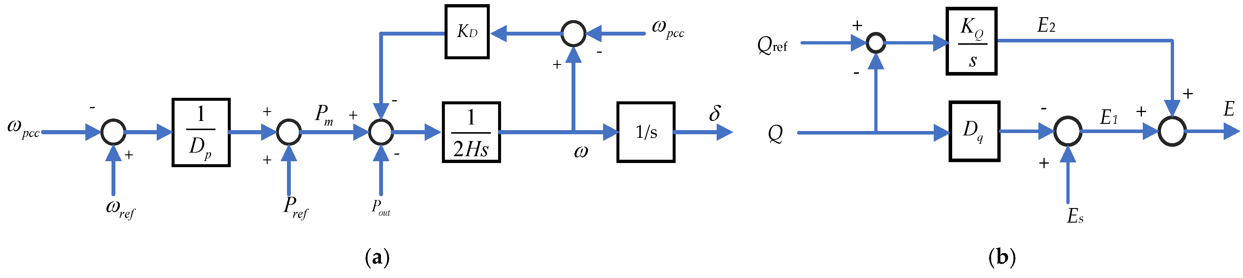
2.1.1. Basic VC-VSC [16]

Professor M. Reza Iravani of the University of Toronto, Canada, proposed a control strategy with a VC-VSC control scheme; its circuit diagram is shown in Figure 1, and its control principle is shown in Figure 2.
The outer power loop is used to simulate the behavior of SG. The mechanical behavior of the SG can be expressed as:
J d w d t = P T w - P E w - K D ( w - w p c c ) + D p ( w 0 - w p c c )
where P T is the mechanical input power, P E is the electromagnetic power of the SG, w is the angular frequency, J is the moment of inertia, w 0 is the rated angular frequency of the generator, w p c c is the measured frequency at PCC. K D is the damping coefficient, and D p is the droop coefficient.
It can also be expressed in the per-unit form:
J S B w 0 × d w d t = P T w × S B w 0 P E w × S B w 0 K D ( w - w p c c ) S B w 0 + D p ( w 0 - w p c c ) S B w 0
That is:
J w 0 2 S B × d w * d t = P T * w * P E * w * K D w 0 2 ( w * - w p c c * ) S B + D p w 0 2 ( 1 - w p c c * ) S B
where SB is the rated power.
The inertia time constant is defined as: H = J w 0 2 / ( 2 S B ) . w * is the per unit angular frequency of SG. Since angular frequency w * varies around the rated value, the w * in Equation (3) of denominator is approximately equal to 1. We have:
2 H d w * d t = P T * - P E * - K D * ( w * - w p c c * ) + D p * ( 1 - w p c c * )
where K D * = K D w 0 2 S B , D p * = D p w 0 2 S B .
For the convenience of writing, all of * in Equation (4) are omitted. Equation (4) can therefore be simplified as:
2 H d w d t = P T - P E - K D ( w - w p c c ) + D p ( 1 - w p c c )
To mimic the power behavior of the SG, the basic control equation of the outer power loop can be obtained as Figure 2a.
2 H d w d t = P r e f - P o u t - K D w - w p c c + D p w r e f - w p c c
where P r e f and P o u t   are command power and output power respectively; w r e f is the reference frequency.
The voltage controller can be operated in two modes: grid-connected mode and autonomous mode. The controller can be expressed in (7).
E = E s - D q Q + K Q ( Q r e f - Q ) s
where Qref is the reference reactive power, Q is the measured output reactive power of the VSG at PCC, KQ is the integral controller coefficient, Dq is the voltage droop coefficient, E is the inverter output voltage, and Es is the reference value of the VSC terminal voltage. In a grid-connected mode, the voltage controller is used to set the output reactive power of the VSC at PCC. The VSG is controlled to output reference reactive power by an integral controller to ensure zero tracking error. In an autonomous mode, the RES unit has to supply the load reactive power without depending on the grid. It is impossible to output a reference reactive power that is not equal to the load reactive power. Therefore, the KQ is set to zero during an autonomous mode. The droop controller is used to distribute reactive power between different converters.

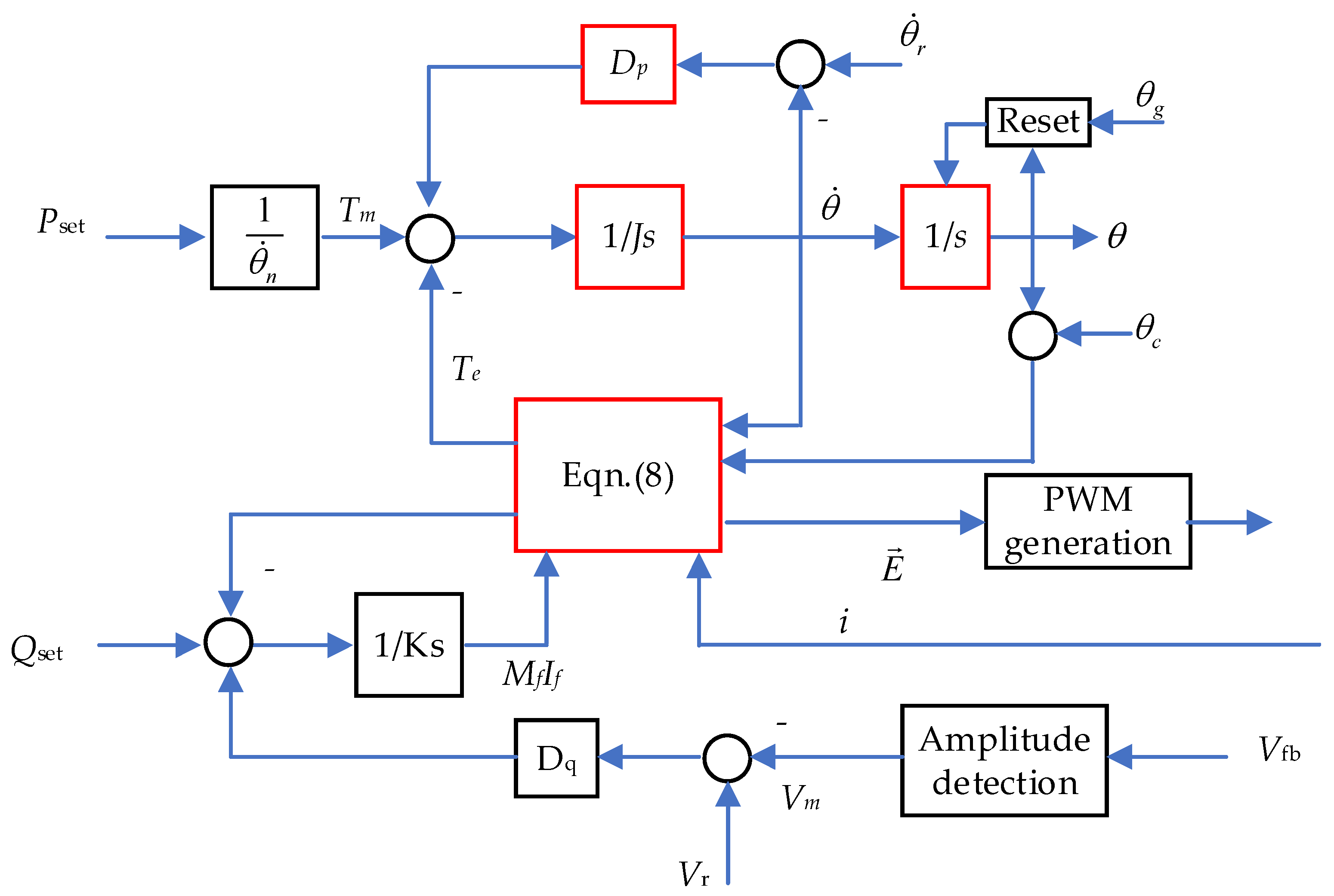
2.1.2. Synchronverter

The electromagnetic transient behavior is not simulated in basic VC-VSC. To overcome this shortcoming, Synchronverter is proposed by Professor Qingchang Zhong of Liverpool University [6]. Its control block diagram is shown in Figure 3. The control of the real power has a nested structure, where the frequency inner loop is a droop loop (with feedback gain Dp) and the power outer loop has more complex structure (with the feedback coming from the current i via the torque Te).
Its power loop equation is:
T e = P E / θ ˙ = M f i f i , sin θ E = θ ˙ M f i f sin θ Q = - θ ˙ M f i f i , cos θ
where sin θ = sin θ sin θ - 2 θ 3 sin θ - 4 θ 3 , cos θ = cos θ cos θ - 2 θ 3 cos θ - 4 θ 3
, denotes the inner product, Tm is the input mechanical torque, Te is electromagnetic torque, ω is the output angular frequency of VSG, Mf is the mutual inductance between the excitation winding and the stator winding, If is the excitation current, θ is the electric angle of the inverter output voltage. θ g and θ c are the angle of grid and VSG voltages, respectively. If the LC filter is neglected, then v f b = v m E = θ ˙ M f i f .
The control of the reactive power also has a nested structure similar to active power control. The inner loop is the reactive-power loop and the outer loop is the voltage loop. The outer loop generates reference reactive power by a droop controller. The input of the droop controller is the difference between the reference grid voltage Vr and the measured grid voltage Vm. If Vr is larger than Vm, the droop controller generates a capacitive reference reactive power to increase the grid voltage and vice versa. The inner loop generates VSG output voltage magnitude to regulate that reactive power.
The time constant τ v of inner loop can be estimated as: τ v K / ( θ ˙ n D q ) . Where θ ˙ n is the nominal angular frequency of the grid. Therefore, K can be calculated when τv and Dq have been determined. The advantage of synchronverter is that transient torque characteristics are more precisely simulated. Furthermore, zero tracking error is realized by the integrators in the active and reactive power control loop. The disadvantage of the controller is that power coupling exists between the active and reactive power control loop. The damping problem of the LCL filter was not taken into account, which may induce resonance in some situations.

2.2. The Current-Controlled VSG

2.2.1. Basic CC-VSG Control Strategy [10]

Its main circuit is the same as that of VC-VSG, which is shown in Figure 1. The outer power loop control equation is:
P m e c h = P i n e r t i a + P d r o o p P i n e r t i a = 2 H d w d t P d r o o p = - D p w - w r e f
Thus, the command power of the VSG can be easily derived:
P r e f = P i n e r t i a + P d r o o p = 2 H d w d t - D p w - w r e f
where Pinertia simulates the inertia characteristics of the rotor, H is the inertia constant. Pinertia simulates the primary frequency modulation power.
After the reference active power value is obtained, the reference active power is needed to be converted into reference current. According to the instantaneous power theory, the instantaneous active power P and reactive power Q of the system are [17]:
P = 3 2 u d i d + u q i q Q = 3 2 u d i q u q i d
If synchronous reference frame is used, u q is equal to zero. Active and reactive reference current can be calculated as:
i d * = 2 P r e f 3 u d i q * = 2 Q r e f 3 u d
where i d * and i q * are active and reactive reference current, respectively. Frequency differentiation is required to calculate the inertia reference power. To apply the control law, the phase-locked loop (PLL) is conventionally used to measured grid frequency and its differential value. However, a frequency-locked loop can reduce the high frequency noises introduced by differential operators compared with the PLL [18]. So, it is more suitable for basic CC-VSG. It cannot respond to the grid frequency variation instantaneously due to the response time of inner current loop.

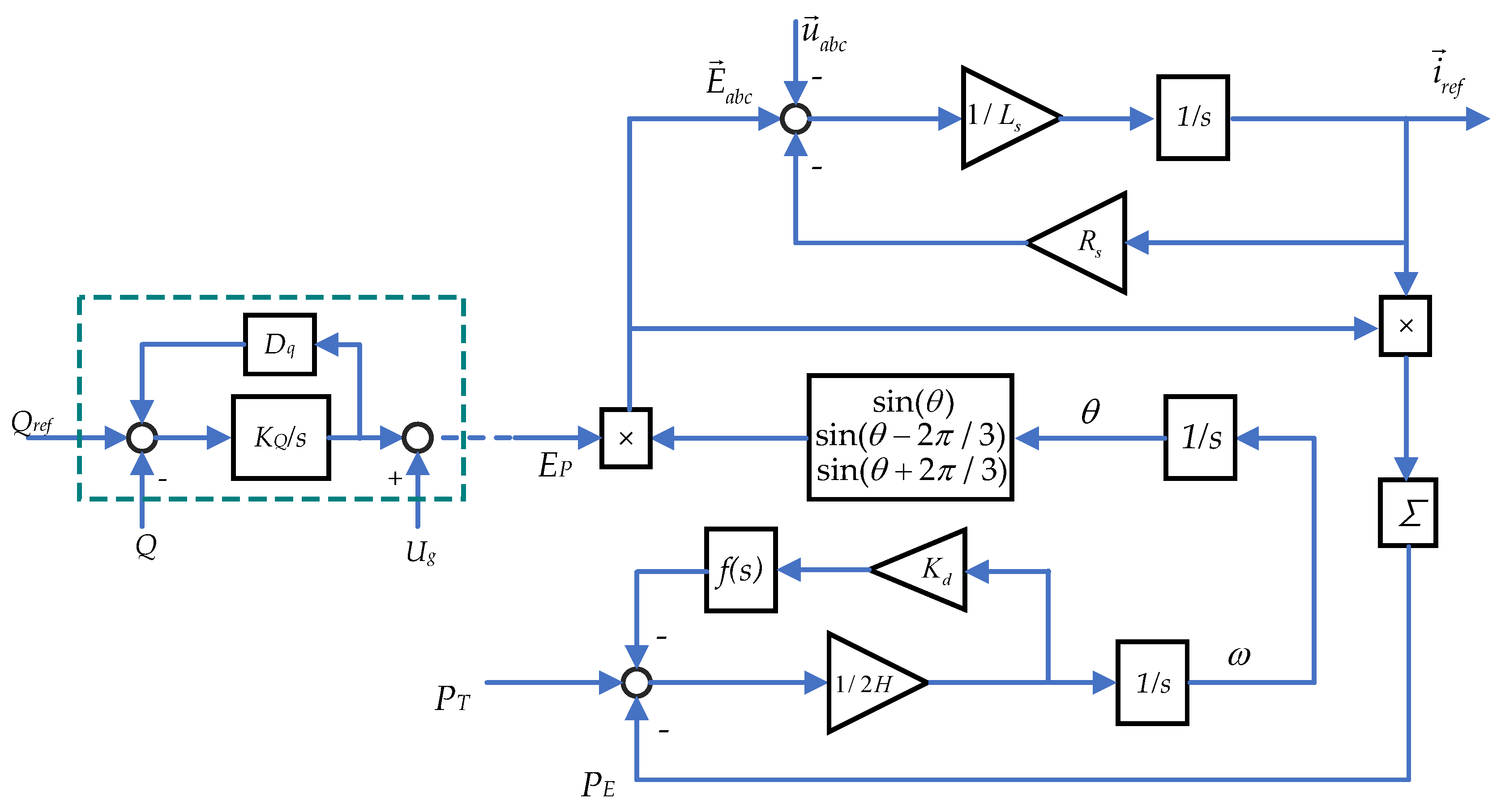
2.2.2. VISMA Control Strategy [19]

Since the electromagnetic equation of SGs is not used in the current inner loop, basic CC-VSG cannot completely simulate the characteristics of SGs. To overcome this shortcoming, the VISMA was proposed by Professor Beck and R. Hesse of the Clausthal University of Technology in Germany. The electromagnetic characteristic of SG is further simulated. Its main circuit is same as Figure 1, and its control principle is shown in Figure 4.
Its outer power loop control equation is:
2 H d w d t + K d f ( t ) d w d t = P T P E
where Kd is the damping coefficient. f(t) is the phase compensation, which realizes that the virtual damping force counteracts any oscillating movement of the rotor in opposite phase.
f(t) can be selected to be a first-order low pass filter [20]. Combined with d w / d t , it is effectively a high pass filter for w . The high pass filter reduces the gain at low frequency range, which reduces the interference of the damping effect with the steady state operation while maintaining transient damping effect.
The stator electrical equation of SGs is:
E a b c = u a b c + R s i a b c + L s d i a b c   d t
where E a b c is synchronous generator internal voltage; u a b c is the generator terminal voltages; i a b c is the stator phase currents; Rs is the three-phase stator winding resistance; Ls is the synchronous inductance.
According to the Equation (14), the command reference i r e f that simulates the dynamic characteristics of SGs stator i a b c can be obtained:
i r e f ( s ) = E a b c u a b c / R s + L s s
where i r e f is the output reference current, Rs and Ls are the virtual stator resistance and inductance, respectively. E a b c = [ e a e b e c ] T , u a b c = [ u a u b u c ] T
E a b c = e a e b e c = E p sin ( θ ) sin θ - 2 3 × π sin θ + 2 3 × π
θ = w d t
where θ is the angle of rotation, Ep is the adjustable amplitude of E a b c .
The VISMA generates a voltage control command similar to the VC-VSG. The magnitude of the voltage command can be obtained by the reactive power control loop, which has been mentioned in the reference. The phase of the voltage command is obtained by the active power control loop. The magnitude Ep and phase are combined together to generate the reference voltage by Equation (16). The voltage command signal is further converted into current command by Equation (15). It can be found that the excitation control of SGs is not simulated in VISMA. Therefore, the sophisticated current control strategy widely used in the grid following converter can be applied. Grid forming is the ability to form a grid autonomously without the help of the main grid. Compared with grid following, it establishes its own angle and voltage reference autonomously without relying on PLL. Grid forming source functions as a controllable voltage source. It can achieve frequency and voltage regulation, black start, islanding and guarantee AC power to critical infrastructure when there is an outage in power grid. The disadvantage of VISMA is that it has no grid forming ability due to the inner current loop.

2.3. Active and Reactive Power Coupling Analysis of VSG

2.3.1. Power Coupling Analysis of VC-VSG

Voltage-frequency (VF) control is used in the inner loop control of VC-VSG. It is assumed that the active and reactive power can be independently controlled by the inverter output voltage and frequency. The active power P and reactive power Q of VC-VSG can be derived from Figure 1 as [21]:
P = U c U g R g cos δ U g 2 R g + U c U g X g sin δ R g 2 + X g 2 Q = U c U g X g cos δ U g 2 X g U c U g R g sin δ R g 2 + X g 2
where Uc is the VSG output voltage. Ug is grid voltage. Rg is grid resistance, Xg is grid reactance. δ is power angle, it is defined as δ = Δ ω d t , Δ ω is the angular frequency difference value between VSG and grid.
Using small signal analysis method and assuming that the steady-state operational points are Uc0 and δ0, we have:
Δ P Δ Q = P δ P U c Q δ Q U c Δ δ Δ U c
where,
k 11 = P δ = 1 R g 2 + X g 2 U c 0 U g R g sin δ 0 + U c 0 U g X g cos δ 0 k 12 = P U c = 1 R g 2 + X g 2 U g R g cos δ 0 + U g X g sin δ 0 k 21 = Q δ = 1 R g 2 + X g 2 U c 0 U g X g sin δ 0 U c 0 U g R g cos δ 0 k 22 = Q U c = 1 R g 2 + X g 2 U g X g cos δ 0 U g R g sin δ 0
where k 12 and k 21 are the cross-coupling term, which are proportional to cos(δ). Since R g X g in most cases, P U c U g sin δ / X g . Since X g is usually less than 0.1 p.u., sin δ is less than 0.1 when the VSG outputs rated power. VSG output power is usually less than the rated power, therefore sin δ is usually very small, and sin δ δ . Since δ is very small, k 12 and k 21 can be further simplified as:
k 12 = P E = U g R g R g 2 + X g 2 = U g R g ( 1 + a 2 ) R g 2 k 21 = Q δ = U c 0 U g R g R g 2 + X g 2 = U c 0 U g R g ( 1 + a 2 ) R g 2
where a = X g / R g . From Equation (21), it can be found out that the cross-coupling is very small if X g / R g is large enough. It is well known that the X g / R g is relatively large in the transmission grid and is relatively small in the distribution grid. Therefore, the VC-VSG control method is more suitable to be applied in the transmission level.

2.3.2. Power Coupling Analysis of CC-VSG

It can be concluded from Equation (12) that the active and reactive power is independently controlled by the dq-axis current, respectively. The active and reactive power coupling are irrelevant to the grid impedance Therefore, the CC-VSG is suitable for both transmission and distribution grids.

2.4. Influence of VSG on Frequency Stability Power System

If a VSG is installed in a weak grid with small inertial, the equivalent system inertia constant is [22]:
H sys = H w g S w g + H V S G S V S G S w g + S V S G
where H w g and S w g are the inertia and rated capacity of the weak grid, H V S G and S V S G are the inertia and capacity of the VSG.
From Equation (22), it can be found out that the equivalent inertia constant of the grid is increased if the inertial constant of VSG is higher than that of the weak grid. From Equation (4), it can be found that the rate of change in the grid frequency (ROCOF) under power disturbance decreases as the inertia constant increases. The grid frequency stability can therefore be improved. In [23], the simulation results show that virtual inertia control can effectively suppress the frequency deviation of the interconnected power system during severe contingencies. The virtual inertia control system provides the desired stability and performance against serious load disturbances under high RES penetration conditions. Therefore, instability and system collapses are avoided. In [24], It is proved that connection stability issues of microgrids can be resolved by virtual inertia control integrating damping properties.

2.5. The Comparison between CC-VSG and VC-VSG

The advantage of CC-VSG is that it is direct control of the converter output current, which makes it easy to guarantee the current quality and prevent overcurrent. However, CC-VSG behaves as a current source for the power grid, which makes it unable to provide grid forming support for the power grid. VC-VSG operates as a voltage source. Therefore, it is able to provide a black start and help to form the grid. It is therefore also called a grid forming inverter. A comparison of the various VSGs is shown in Table 1.
The VC-VSG has attracted more research interest than the CC-VSG during to its inherent advantage. Various improved control strategies have been proposed. To improve the control stability, voltage and current double closed-loop control were added into VSG [25]. To improve power balancing and oscillation suppression ability, the virtual impedance was added to the control loop [26].

3. Hardware Configuration of VSG

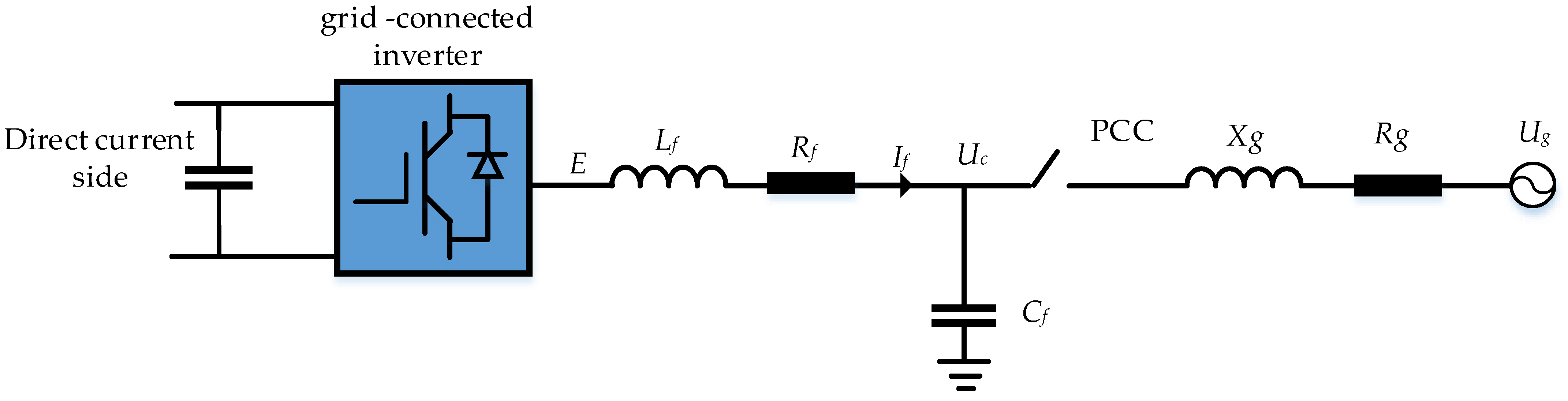
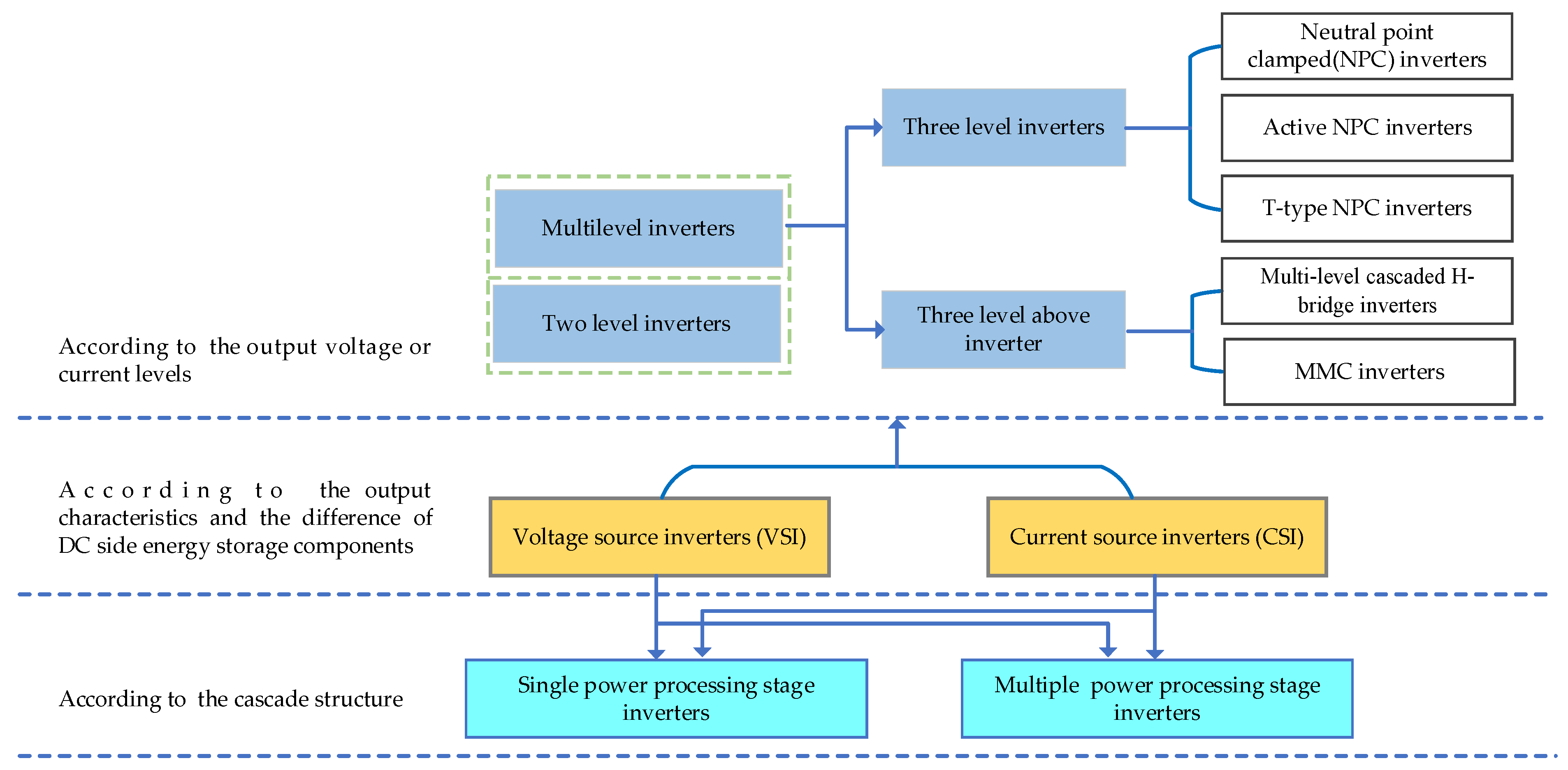
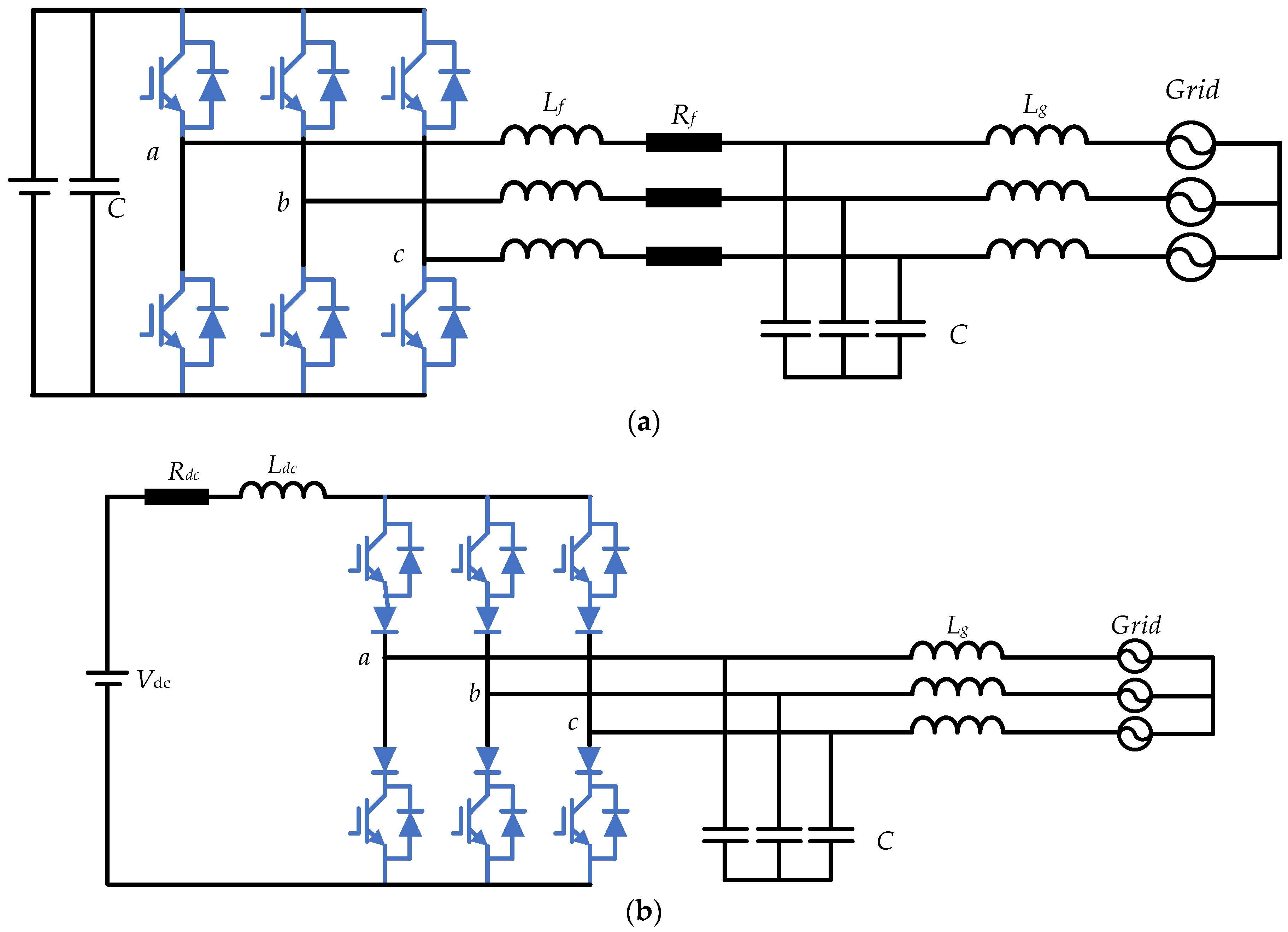
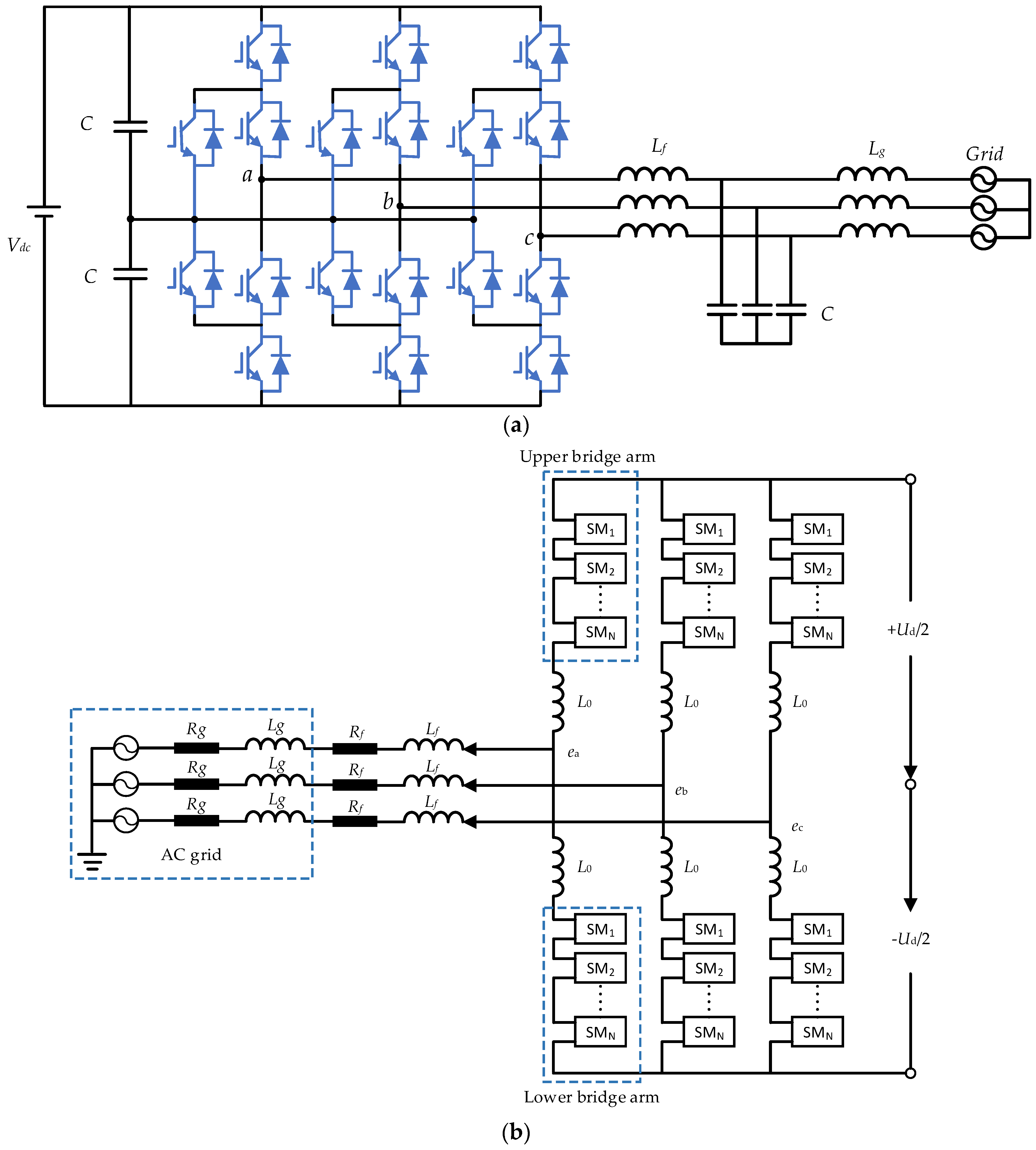
3.1. Topology of VSG

Multiple converter topologies can be used to realize VSG. It can be classified as Figure 5 [28]. The basic topologies are current source inverters (CSI) and voltage source inverters (VSI) topologies shown in Figure 6, which are based on the output characteristics and the difference of DC side energy storage components. The comparison of performance and structure between VSI and CSI is shown in Table 2 [29].
VSI utilizes a capacitor as a DC side energy storage device to ensure stable DC link voltage. CSI utilizes an inductor as a DC side energy storage device to ensure stable DC side current. Compared with the inductor of CSI, the capacitor of VSI has obvious advantages of its small size, low cost, and high energy storage efficiency. In addition, CSI requires the use of reverse-blocking semiconductor devices, which usually have higher conduction losses than reverse-conducting semiconductor devices used in the VSI [30]. The VSI voltage DC bus also allows direct connection to voltage source energy storage devices (ESDs) such as batteries and supercapacitors [31,32]. Therefore, the VSI is more commonly used [33].
Although two-level converters are usually in the VSG, multilevel converters have more advantages. The voltage on each switching device is less than the output voltage. Moreover, they can provide high quality power with less harmonic distortion. The three-level neutral point clamped (NPC) converters are used in [34]. Compared with three level NPC converters, three level active NPC shown in Figure 7a have more advantages. It can further reduce switching loss. In [35], the VSG is proposed to control the multi-level cascaded H-bridge converter to improve the frequency stability in island operation of the microgrid. Modular multi-level converter (MMC) shown in Figure 7b based multi-terminal high voltage direct current system (MTDC) has many advantages, such as multi-source point, multi-infeed power supply, and flexible power flow regulation. The VSG control is applied to the MMC-MTDC system, which makes it able to suppress low-frequency oscillation and improve the damping performance [36,37].

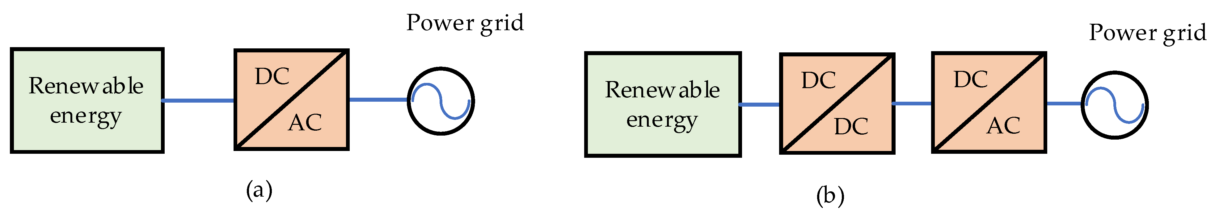
3.2. Power Conversion Stages of VSG

According to the difference in power conversion stages, there are two main kinds of VSG circuit configurations: single-stage VSG and dual-stage VSG. As shown in Figure 8a, the single-stage VSG connects the RESs or ESDs directly to the DC link of DC/AC converter, which outputs the power directly to the AC grid. Since only one energy conversion stage is needed, it has higher energy conversion efficiency than the dual-stage VSG. As shown in Figure 8b, the dual-stage VSG connects the RESs or ESDs to the grid through DC/DC and DC/AC converters. The advantage of this configuration is that it has a larger DC voltage regulation range. Therefore, it has higher energy and power utilization rate.

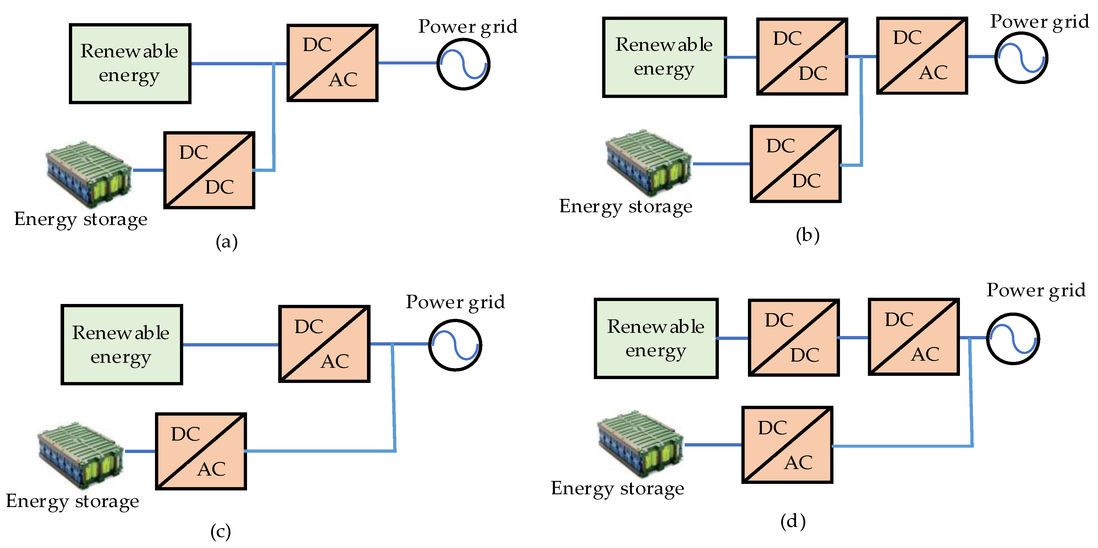
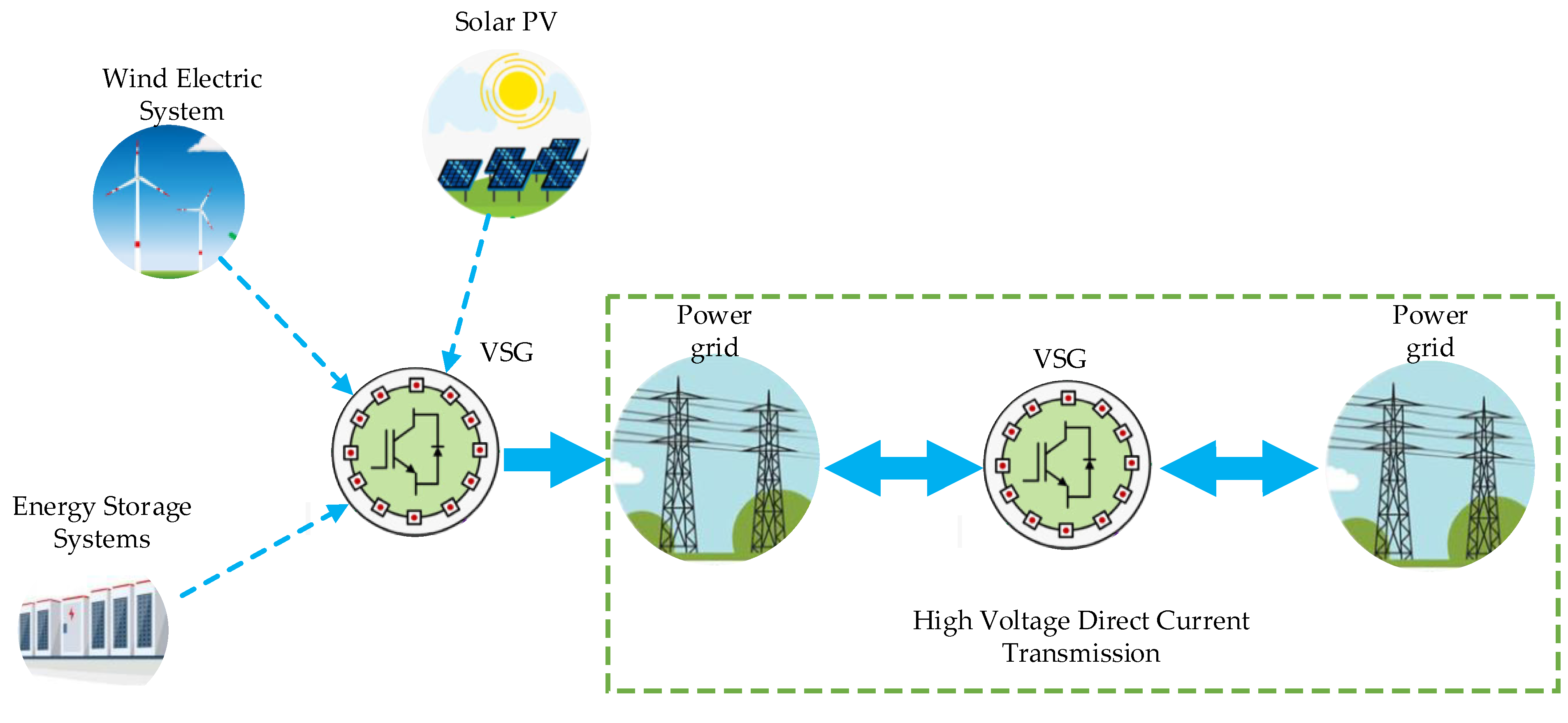
3.3. Integration of RES and ESD in a VSG

The RES and ESD can directly form VSGs by proper control. However, they can also be integrated together to form a VSG so as to improve the cooperation between each other. They can be integrated at DC or AC buses.

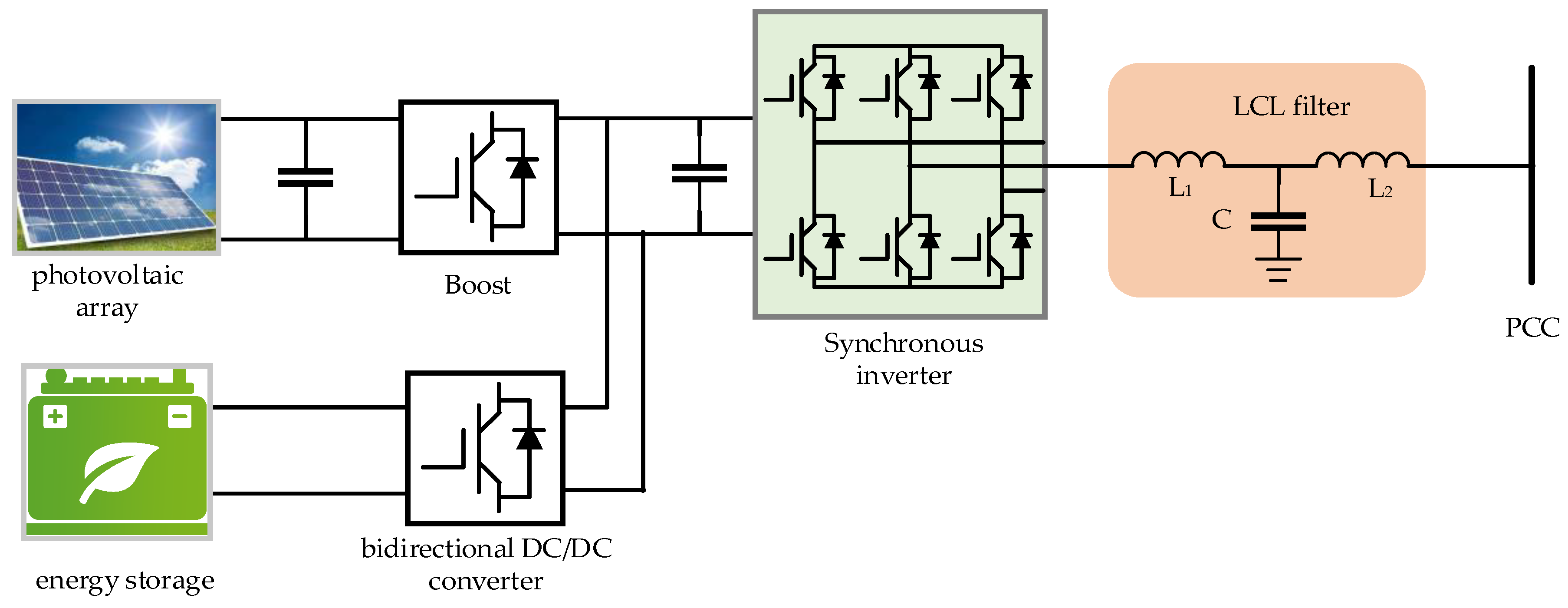
3.3.1. Common DC Bus Single-Stage VSG

The topology is shown in Figure 9a. The RES is directly connected to the DC/AC converter while the ESD is connected to the DC/AC converter through a DC/DC converter. The DC link voltage is controlled by the DC/DC converter variably to make the RES operate on its maximum power point (MPP). The RES output power is usually fluctuating, the DC/AC converter outputs the smoothed RES power with the help of the ESD. The DC/AC converter is also used to provide inertia support and frequency regulation to the grid. The advantage of this topology is that it has only one conversion stage to the RES, which makes it have high efficiency.

3.3.2. Common DC Bus Dual-Stage VSG

The topology is shown in Figure 9b. Both RES and ESD are connected to DC link through independent DC/DC converters, which enable independent control of RES and ESD. RESs are operated at the MPPT by the DC/DC converter connected to the RES. Frequency regulation power is supplied by the other DC/DC converter connected to ESD. The DC link voltage is controlled to be constant by the DC/DC converter connected to the ESD. The DC/AC converter is also used to smooth the RES power, provide inertia support and frequency regulation to the grid [38]. The advantage of this topology is that it has a wider MPPT range compared to that of the single stage VSG.

3.3.3. Common AC Bus VSG

The topology is shown in Figure 9c,d. For common AC bus VSG, both single and dual-stage topologies can be used. Since the RES and ESD are independently connected to the grid, decoupling power control can be realized in both topologies. The MPPT control is implemented in the RES converter. The VSG control is implemented in the energy storage converter [39,40]. Grid frequency fluctuations can be suppressed by the ESD immediately. RES power fluctuations are also suppressed by the ESD.

4. Software Control Method of VSG

Due to its independent active and reactive power control ability, the control of VSG can be classified into the following two types: active power frequency stability control and reactive power voltage stability control.

4.1. Frequency Stability Control of VSG

Droop control is usually used for primary frequency regulation. The advantage of droop control is its simplicity and good power sharing capability. However, it does not consider the transient frequency response and cannot provide inertia support to the grid. To provide inertial support, controllers are designed based on the swing equation to imitate both static and dynamic characteristics of the SG [41]. However, the introduction of inertia support makes the VSG prone to inducing power oscillation [42]. Compared with SG, parameters of VSG, such as inertia and damping coefficients, can be adjusted on line, which makes it flexible for control performance optimization. The basic active power control block diagram is shown in Figure 2a.
In the inner current/voltage loop, a PI controller is commonly used [43]. In the outer power loop, to suppress the frequency and power fluctuations of the VSG, advanced solutions are proposed. The basic idea of the solutions is to adaptively change the inertia and damping ratio of VSG during large disturbances so as to improve the control performance [44,45,46].

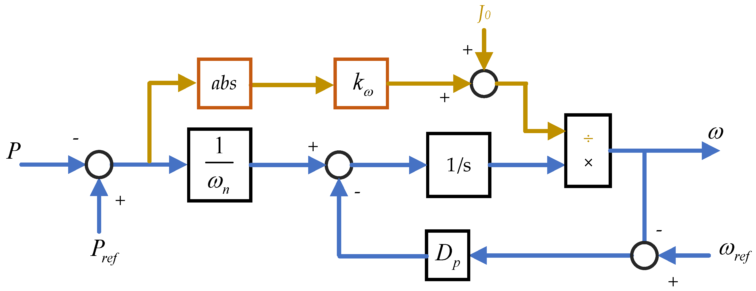
4.1.1. Adaptive Virtual Inertial Control

Larger virtual inertia value H enables the distributed generator (DG) to supply more power to reduce frequency deviations during transient events [47]. The undesired over df/dt fault triggering could be avoided if adequate inertia is provided. Therefore, the inertia coefficient can be modified as a function of df/dt. The control can be expressed as:
H = H 0 , d f / d t < M H = H max , d f / d t M
where H0 is the inertia value in steady-state operation, M is the threshold of the frequency change rate. Under normal operation, the measured frequency change rate value is below the threshold M and the value of the inertia coefficient remains at H 0 . On occurrence of a large disturbance, |df/dt| exceeds the threshold value M, and the inertia coefficient is switched to a maximum value. The proposed control switches the virtual inertia between a small and a large value, which induces oscillation during the virtual inertia transition.
Considering the frequency recovery process, an improved adaptive control strategy with varying moments of inertia is proposed in [45,48]. When prime mover power command changes from one value to another, the output power will oscillate and converge to a new command value. The oscillation modes are summarized in Table 3. The sign of d w / d t and Δ w determine the power acceleration or deceleration. In order to damp power oscillation, a large value of J is selected to restrain frequency acceleration; a small value of J is selected to boost the deceleration.
Another adaptive power-angle control method is proposed in [49], which prevents VSGs from crossing over the unstable equilibrium point along the power-angle curve after the disturbance. It is shown in Figure 10, Where G δ P ( s ) is transfer function from δ to Pe, i.e., P e = U c U g sin δ / X g .
According to the swing equation 2 H d w / d t = P r e f - P e , w increases from b to c due to Pref> Pe. δ also increases according to δ = Δ w d t . From the point c to e, w decreases due to Pref < Pe. Before w decreases to w g , Δ w remains positive. δ continues to increase. If w fails to recover to w g , ω increases again due to Pref > Pe, and δ keeps increasing. Since P e U c U g sin δ / X g and δ > π/2, Pe will further decrease due to the increasing δ, which causes the power control error Δ P = P r e f P e to be enlarged. A positive-power-angle feedback mode therefore occurs, and the synchronization between VSG and the grid is lost. So, e represents the critical stability point. In order to avoid the positive-feedback mode, a variable k is introduced, which is set as 1 in the negative-feedback mode and −1 in positive-feedback mode as shown in Figure 10b. It prevents positive-feedback operation of the power-angle control of the VSG. Thus, the risk of loss of synchronization can be avoided [49].
The power change rate is further taken into account to change the moment of inertia so as to limit the frequency change rate [50]. Since the ROCOF is mainly related to the output power and inertia, the output power deviation is used to change the moment of virtual inertia. The larger the power deviation, the larger moment of virtual inertia is used. The output frequency change rate is therefore limited. The control block diagram is shown in Figure 11. Where k ω is the adaptive inertia coefficient, Dp is the damping coefficient. The active power transfer function is second order due to the existence of an inertia loop, whose dynamic performance is less smooth than first order one. In [51], proportional power feedforward control is used, which adds a zero in the transfer function to cancel one pole in the active power loop. The order of the active power control loop is therefore reduced from two to one.

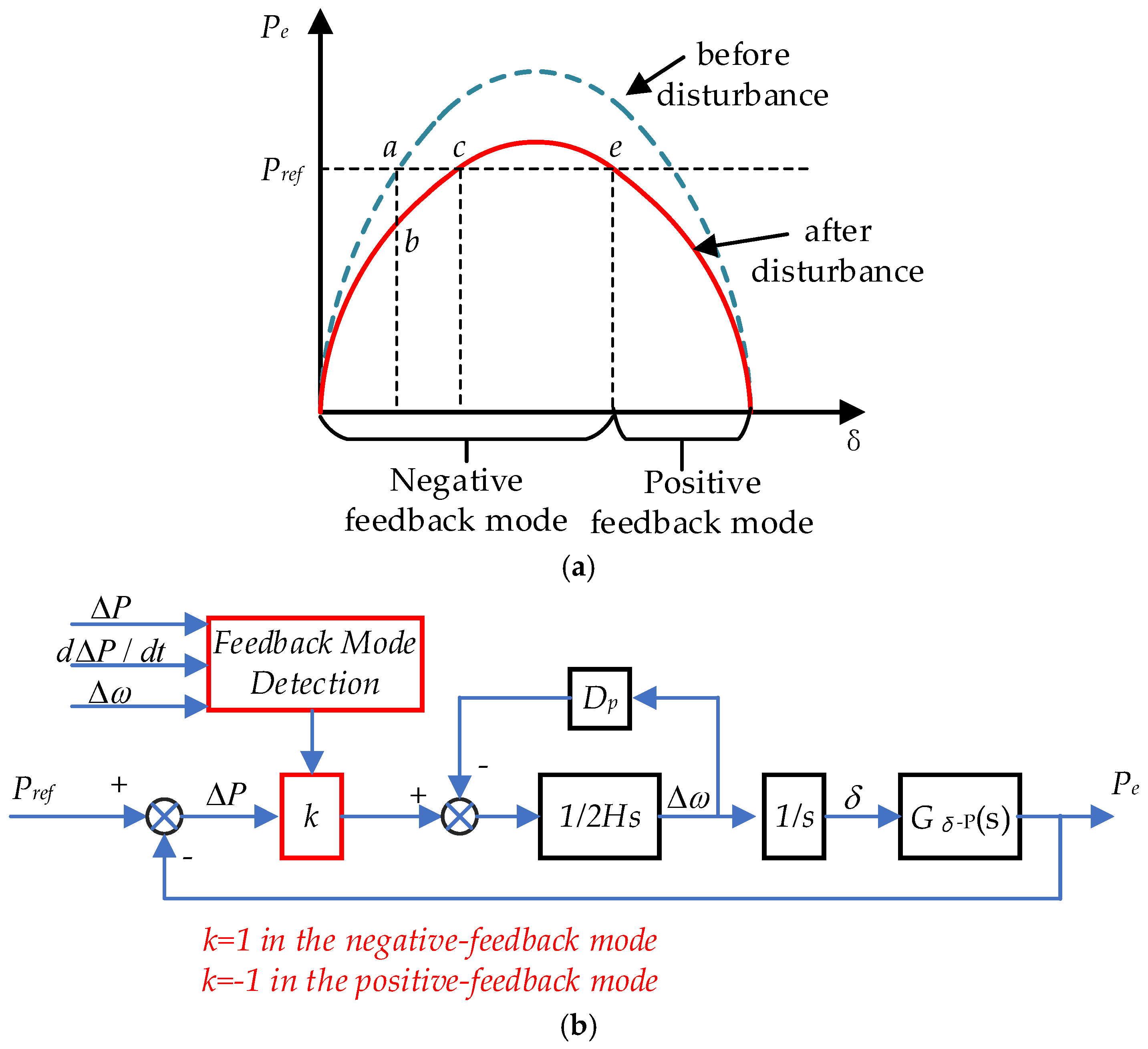
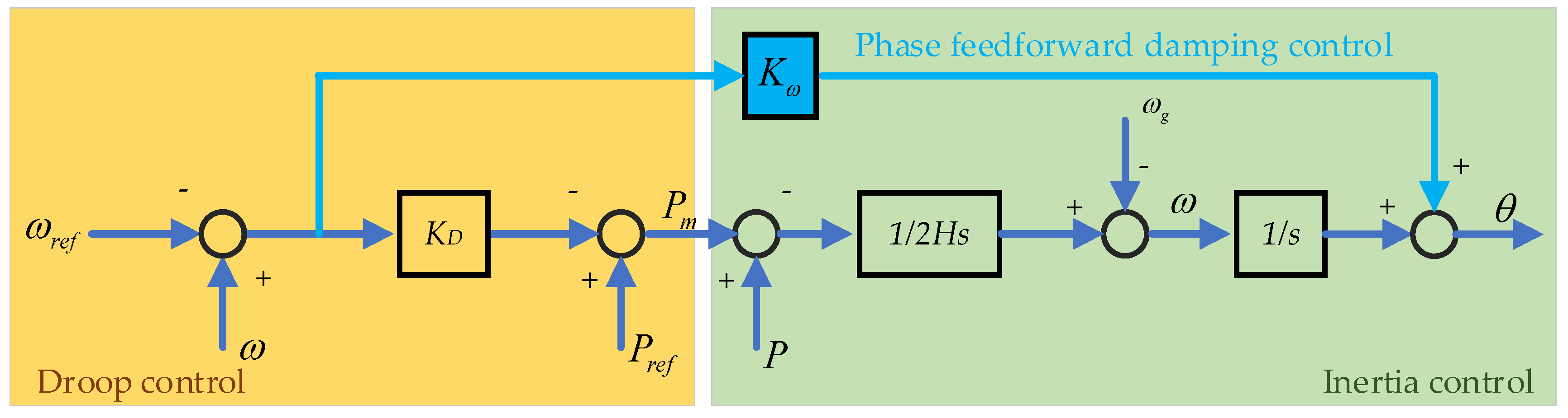
4.1.2. Adaptive Power Damping Control

Not only inertia, but also damping influences VSG frequency stability. In [6,52], the damping coefficient is equivalent to the droop coefficient, which makes the model simple by eliminating governor. The function of the droop coefficient is to provide the frequency-supporting, whereas the function of the damping factor is to suppress the oscillation modes of the control system [53]. The optimal ranges of the droop coefficient and the damping factor usually do not overlap. In order to eliminate the interactions between the droop and the damping control, a phase feedforward damping control (PFD) method for VSG is proposed to decouple the damping control from the droop control, which is shown in Figure 12 [53], where k ω is the phase feedforward gain.
The closed-loop transfer functions of conventional VSG(C-VSG) and phase feedforward damping VSG (PFD-VSG) from the grid frequency disturbance to the output active power can be expressed as:
G C - V S G = Δ P Δ ω g = K p ( 2 H s + K D + D p ) 2 H s 2 + ( K D + D p ) s + K p
G P F D - V S G = Δ P Δ ω g = K p ( 2 H s + D p ) 2 H s 2 + ( D p + K ω D P K p ) s + K p
In steady state, the output power to suppress frequency change is:
Δ P = lim s 0 G C V S G Δ ω g = K D + D p Δ ω g
Δ P = lim s 0 G P F D V S G Δ ω g = D p Δ ω g
where K p = U c U g / X g , comparing (26) and (27), it can be seen that the equivalent droop coefficient of C-VSG changes from Dp to KD + Dp due to the effect of the damping control. Whereas the droop coefficient of PFD-VSG is always Dp and free from the influence of the damping control.
However, the above-mentioned methods do not co-operate inertia and damping control effectively. A self-adaptive inertia and damping co-operational control method to improve the frequency stability with an interleaving control technique was proposed in [46,54]. It decreases the frequency deviation while reduces the stable settling time compared to the conventional methods.

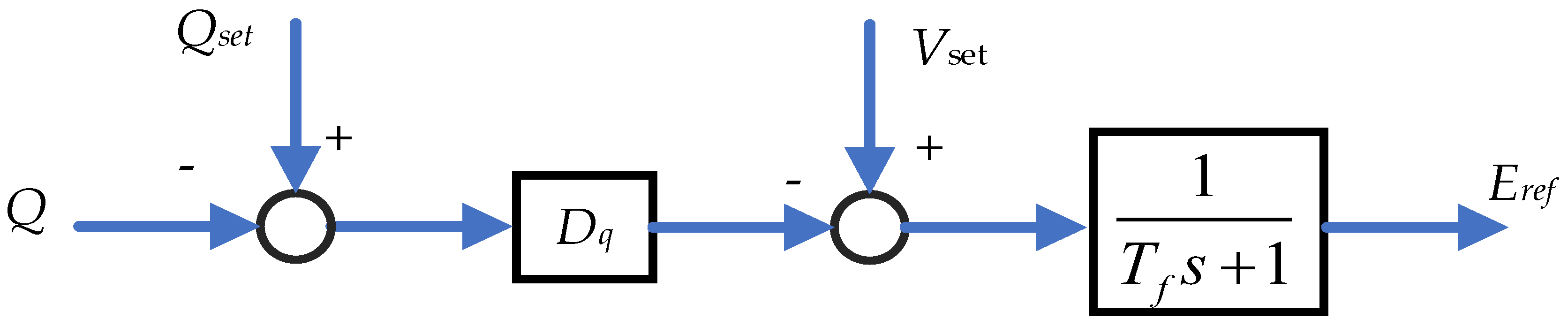
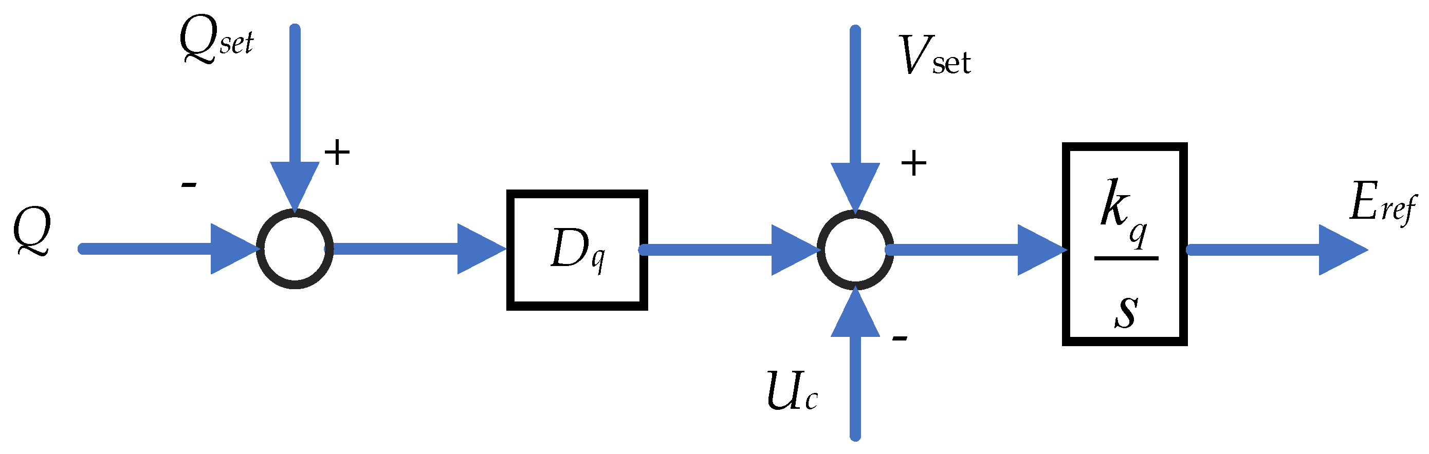
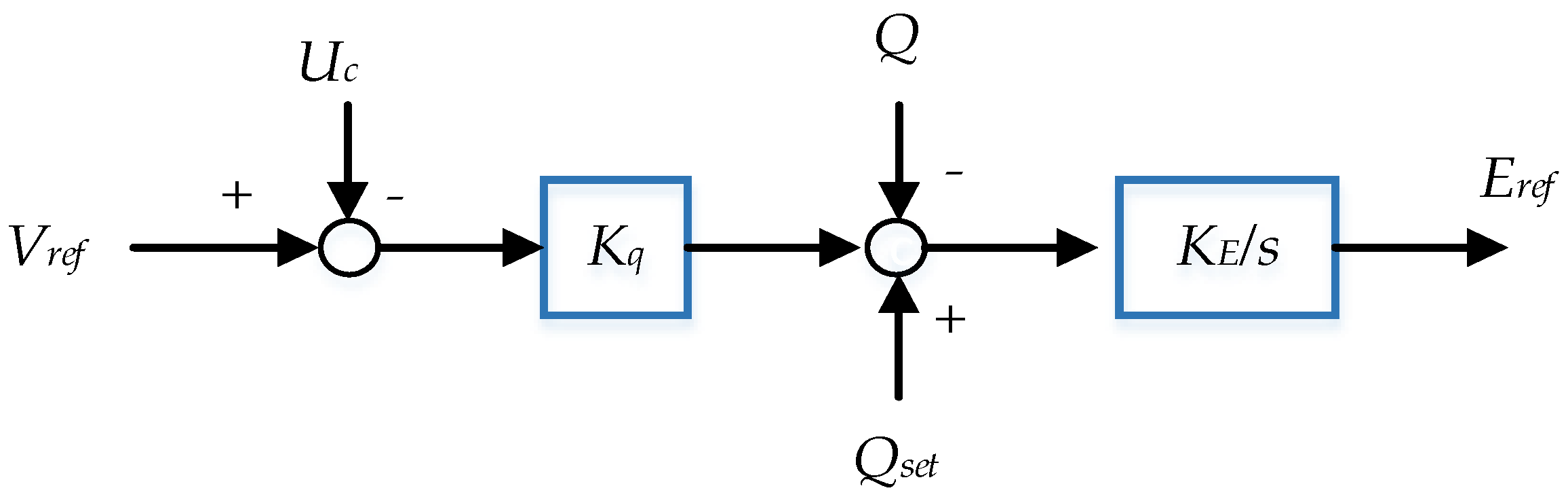
4.2. Reactive Power Control of VSG

In addition to active power frequency control loop, reactive power voltage control loop is also a key issue. For the VSG, the reactive regulation methods are more flexible compared with SG. The reference voltage is generated by reactive power droop control [55], as shown in Figure 13. The droop control realizes the reactive power sharing among different VSGs. The Eref is can be expressed as:
E r e f = 1 T f s + 1 V s e t + D q Q s e t Q
where Eref is output voltage reference of VSG. Tf is the time constant of the power filter. Qset is reactive power setting value. Vset is nominal voltage setting value.
In [56], another voltage control strategy was proposed, which combines the Q-droop control with an integrator (defined as droop-I). It is shown in Figure 14. The droop-I control takes both the reactive power and terminal voltage as the feedback signals. Then the Eref can be expressed as:
E r e f = k q s V s e t U c + D q Q s e t Q
where kq is an integral gain.
Both voltage control methods are commonly used [57]. They are compared in [56]. It is concluded that the Q-droop control has better robustness subjected to Vset variations. The droop-I control has a better steady-state regulation characteristics and is not easily affected by the inner loop and virtual impedance. Based on droop-I control, PI controlled is used to regulate the amplitude of Eref in [58].
Different from reference [56], another control strategy is proposed as shown in Figure 15 [59], where kq and kE are the droop coefficient and the integral coefficient of reactive voltage, respectively. The Q–V droop mechanism is introduced by making Qref = Qset + kq(VrefUc). Since UcUg, the VSG can automatically change its output reactive power according to the grid voltage.
Fixed droop coefficients are usually used for regulation of voltage, which has drawbacks such as slow dynamic response and poor voltage regulation. The virtual impedance loop-based droop method was designed to improve the dynamic response and reactive power-sharing capability in [54]. In [60], voltage regulator is redesigned based on a sliding-mode control technique, the voltage deviation rate is reduced greatly by the feedback structures.

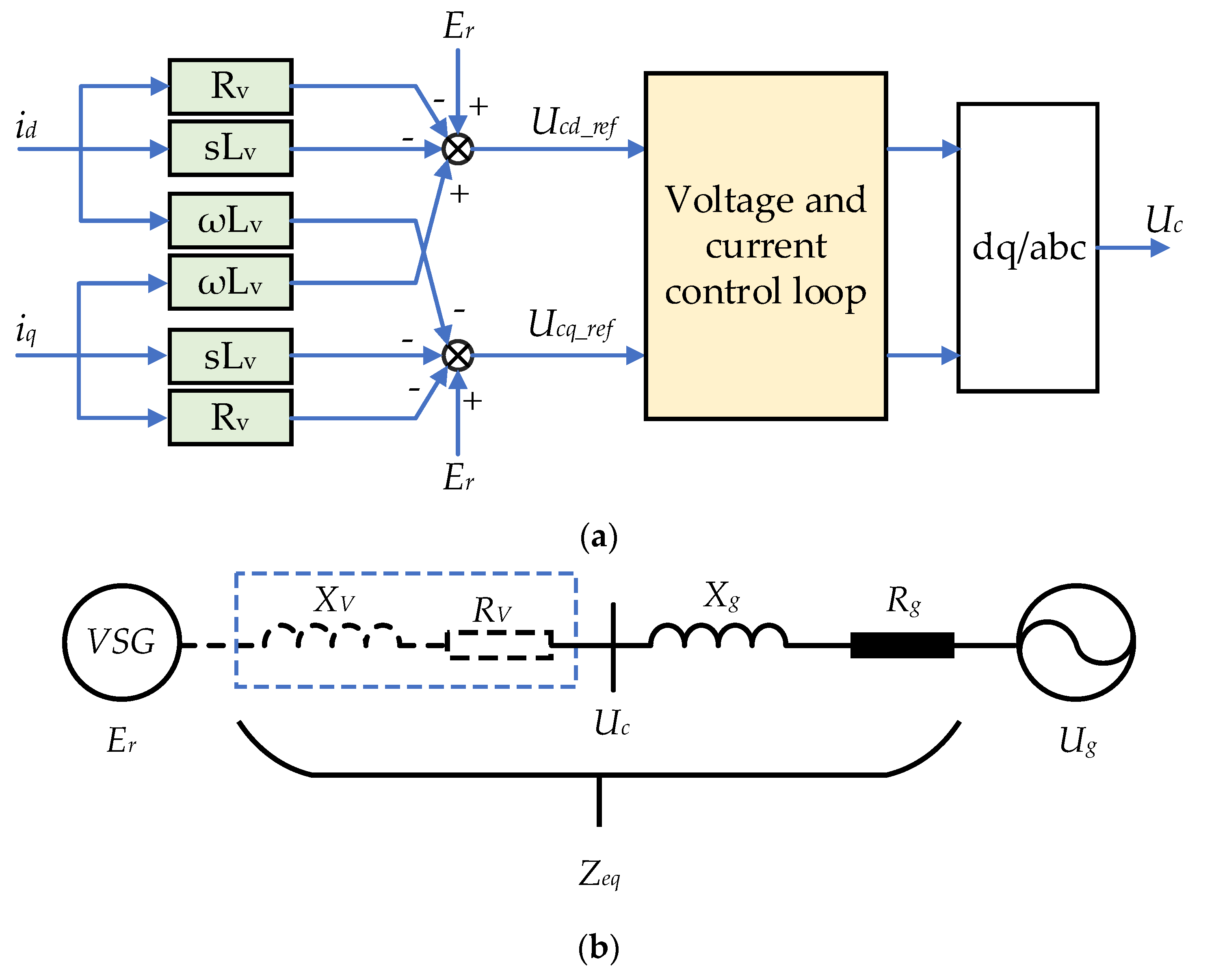
4.3. Power Decoupling Control of VSG

The above-mentioned controller methods are designed under the assumption that there is no coupling between active and reactive power control loop. However, under weak grid conditions, the coupling between active and the reactive power cannot be neglected for the VC-VSG. The virtual impedance method is most commonly decoupling method. In [61], a virtual complex impedance method is proposed. The control block diagram is shown in Figure 16a. The virtual impedance control is implemented through modifying reference output voltage. The final VSG output reference voltage is the reactive power control loop generated reference voltage minus the virtual impedance voltage, which is expressed as:
U c _ r e f ( s ) = E r ( s ) - R v + s L v I ( s )
where E r is the voltage reference generated by the reactive power control loop, U c _ r e f is the final VSG output voltage reference. R v and L v are virtual resistance and virtual inductance, respectively. U c is controlled by voltage and current dual closed-loop. The fundamental equivalent circuit with virtual impedance is shown in Figure 16b. The grid equivalent impedance Z e q is R e q + j X e q = R g + R V + j ( X g + X V ) . R e q and X e q are equivalent grid resistance and inductance, respectively. The virtual complex impedance Zv(s) is composed of Rv with a negative value and Xv with a positive value. The Lv is designed to increase the equivalent grid inductance, and Rv is designed to reduce the equivalent grid resistance. It makes the equivalent a = X e q / R e q larger. k12 and k21 are reduced according to Equation (21). As a result, the power decoupling was reduced. In [62], it is pointed out that the decoupling capability of the virtual inductor is limited by the d-axis voltage drop across the virtual inductor. A q-axis voltage-drop-based power decoupling control is proposed to further reduce the power coupling.
However, the active power sharing performance during the transient state is still easily influenced by the line impedance. An adaptive Fuzzy-Neural-Network Power decoupling method is proposed in [63], which not only realizes the power decoupling but also avoid dynamic response deterioration by the variations of virtual inductors. In [64], the low inductance-to-resistance ratio (X/R) of the grid impedance is fully considered. A coordinated voltage–frequency support scheme for VSGs connected to LVDGs is proposed.

5. Energy Supporting Ways

Inertia support and primary frequency regulation need energy supplied either from the ESDs or the RESs. Without ESDs, The RESs operate below the MPP, so as to provide active power reservation (PR) to support the grid. The characteristic comparison between the two methods is shown in Table 4 [65]. From the perspective of initial investment, the PR method is more economical compared with the energy storage method. However, the RES cannot operate in MPPT mode with the PR method; the RES power generation efficiency cannot be maximized. Furthermore, the frequency regulation capability of the PR method is very dependent on weather conditions. When RES output power is low, the frequency regulation capability is also weak. For example, the PV cannot output power at night. Therefore, it is impossible to regulate the grid frequency with the PR method under this condition.
The difference between inertia support and primary frequency regulation is shown in Table 5. The role of inertia support is to delay the frequency change rate caused by the power imbalance of the grid, so as to gain time for primary frequency regulation. The inertia support delaying frequency change rate is a transient power support with very short time, which requires high power but very limited energy. So, the high-power density ESDs with fast responding speed is needed during the inertia support. The function of frequency regulation is to provide continuous active power support in response to the grid frequency deviation. Since the frequency change rate during this process is low, it does not need fast response and high power to adapt this situation. So, the low power density high energy density ESDs are needed during frequency regulation.
Several kinds of energy storage devices can be used to provide energy support for inertia and primary frequency regulation of VSG, including supercapacitor energy storage, flywheel energy storage, battery energy storage, superconducting magnetic energy storage, etc. The characteristics of these energy storage devices are shown in Table 6. Detailed characteristics about all these types of energy storage are summarized as following.

5.1. Superconducting Magnetic Energy Storage

The superconducting magnetic energy storage (SMES) stores energy in a superconducting coil in the form of magnetic field. This magnetic field is created by the flow of a direct current (DC) in the coil. During a magnetic field formation in superconducting coil, the resistive loss is negligible. The energy conversion process in the SMES system is only from AC to DC, there are none of the inherent thermodynamic losses associated with conversion of one form of energy to another [68]. Therefore, it has the fastest response and longest lifetime features compared with other energy storage. Due to the above advantages, it is promising to provide inertia support to the grid [69]. A robust decentralized frequency stabilizer integrated with the SMES is proposed in [70]. To optimally utilize the energy capability of the SMES while keeping the state of charge (SOC) within a safe range, a novel multi-input multi-output fuzzy logic controller (FLC) is proposed in [71]. In [72], the SMES connected in the DC link of VSG- High Voltage Direct current (HVDC) system was used for compensation of power fluctuation caused by the RESs.

5.2. Flywheel Energy Storage

Flywheel energy storage (FESS) is an advanced physical energy storage technology. It stores the energy in the form of kinetic energy. It has good properties of a low maintenance cost, free from depth of discharge effects, high efficiency, and long operation life [73]. The kinetic energy is proportional to the flywheel mass and square of the rotational speed. To increase in kinetic energy, increasing rotational speed is more effective method compared with increasing the flywheel mass. Initially, steel was used to make the flywheel. However, it is not able to operate at high speed. Later, composite materials were applied. The use of composite materials significantly increases the rotational speed and power density [74]. By regulating the speed of the flywheel in proportion to the grid frequency, the flywheel serves as an energy buffer that absorbs and releases its kinetic energy to provide inertia support or frequency regulation [75]. In [76], RESs and flywheel energy storage are integrated to participate in frequency regulation, which effectively improves the inertial response to the power systems.

5.3. Supercapacitor Energy Storage

A supercapacitor has the characteristics of high-power density, long life, fast response. The terminal voltage of supercapacitor can vary widely, which ensures a high energy utilization rate. It is a promising candidate for providing inertia support [77]. However, due to low energy density, it is not suitable for frequency regulation support. In [78], with the help of supercapacitor energy storage, the type-IV wind turbine (WT) is controlled as VSG. The calculation of the supercapacitor capacity regarding the grid frequency support capability is presented. It is suggested that supercapacitor is a good candidate to supply virtual inertia to the grid. A new control strategy to provide virtual inertia through a supercapacitors-based isolated ESS with a grid-forming inverter was proposed in [79]. The control strategy includes a synchronization controller, that ensures a soft grid connection, and a SOC controller to ensure that the supercapacitor energy level is always within an acceptable range.

5.4. Battery Energy Storage

Compared with other energy storage technology, battery energy storage (BES) is another technology that has been commercialized for grid application. Its energy density is higher than the other candidates. Whereas, its power density is smaller than the other candidates. In addition, its lifetime will be significantly shortened under the high-frequent charging and discharging operation, so it is not a good choice for inertia support. To extend the service life, batteries are connected to the DC-link capacitor via a converter for buffering the power imbalance between grid side and renewable energy side. The DC-link capacitor is used to provide inertial support for the power grid. The power for the frequency regulation is provided by BES [80]. However, the DC-link voltage stability margin is not considered in the paper. In [81], when the DC-link voltage is within the predefined safe range, the PV source operates at MPPT mode and the DC-link capacitor provides the power for inertia support. Meanwhile, droop control is implemented to associate the battery power with the DC-link voltage. When the DC-link voltage goes beyond the safety margin, PV de-loading and inverter rectification will be adaptively activated to restore DC-link voltage to the predefined range.

5.5. Hybrid Energy Storage

The ideal energy storage for VSG needs high power density and long cycling life for inertial support and high energy density for primary frequency regulation [82]. Although supercapacitor, low speed FESS, and SMES have a lot of advantages for inertia support, they are unable to provide enough energy for primary frequency regulation due to their low energy density. In order to fulfill the requirement of VSG, it is usually recommended to combine high-power density ESDs with BES. Therefore, high-power density ESDs such as ultracapacitors and flywheels are suggested to be integrated with battery, which is called hybrid energy storage systems (HESS), for providing inertial response and primary frequency response simultaneously [83,84]. In [85], the battery is used for compensation of low-frequency power fluctuations, and the ultracapacitor is used for compensation of high-frequency power fluctuations.

6. Applications of VSG in Power Systems

According to different application scenarios, VSGs are classified into renewable energy VSG, HVDC transmission VSG, and energy storage VSG. Renewable energy VSG includes wind VSG, photovoltaic VSG. The various applications are shown in Figure 17.

6.1. Application of VSG in Photovoltaic Power Generation

The photovoltaic (PV) is intermittent in nature, and does not match the load profile. As a result, large-scale integration of distributed PV challenges the quality and stability of the grid [13]. Photovoltaic synchronous generators (PVSG) are a promising solution [86]. Many PVSG topologies have been proposed. The most typical one is shown in Figure 18. PV and ESD are connected to the common DC link through independent DC/DC converters. PV is controlled in MPPT mode to maximize power output. The energy storage system is used to smooth the active power output and reduce the negative impact on the grid [87].
Considering the time varying characteristics of photovoltaic power supply, a PVSG which takes the dynamic characteristics of PV power supply into account is proposed in [88]. A robust VSG control method is proposed in [89]. The voltage stability of a stand-alone PV station is enhanced by reactive power control of VSG. A test method for rotating inertia and damping of PVSG based on power frequency transfer function is proposed and verified by a hardware in the loop simulation platform [90]. The challenge for PVSG control is the coordination strategy of PV, ESD and grid-connected inverter [91].

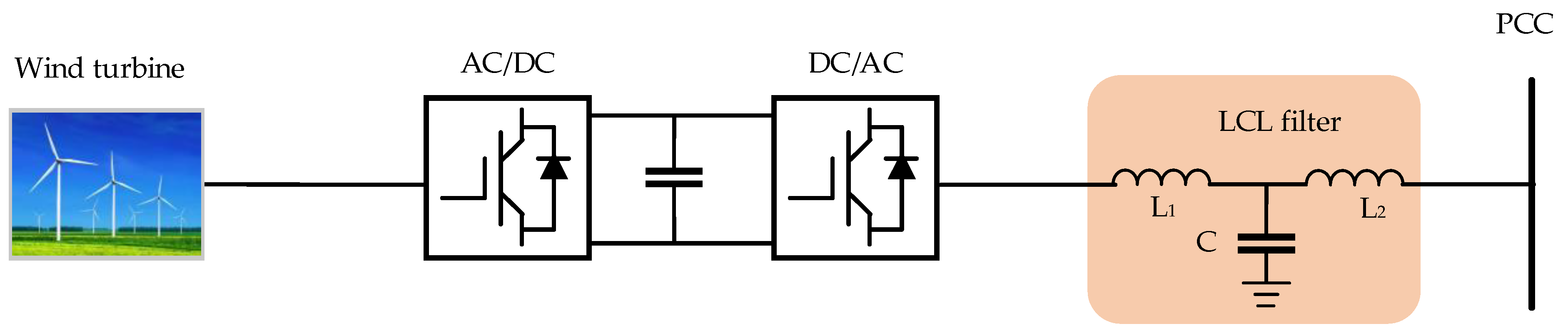
6.2. Application of VSG in Wind Power Generation

The wind turbines (WTs) are controlled by converter, which are usually controlled under MPPT mode and its rotating speed is decoupled from grid frequency variation. Therefore, the WTs cannot provide frequency support to the grid, and the power fluctuation is balanced by conventional SGs [92,93]. With the increase in WTs penetration, the grid inertia decreases consequently, degrading the stability of the grid. Recent research shows that grid-connected converters with VSG controller have strong self-regulation ability of frequency and voltage [94]. Figure 19 shows a schematic diagram of wind power generation VSG.
So far, frequency control methods of VSG based WTs can be generally divided into two categories: the emulated inertia control (EIC) and the de-loading operation-based primary frequency control (DOPFC) [95,96]. The mechanism of the EIC is that it utilizes the rotor kinetic energy (KE) to provide short-term frequency support so as to improve the dynamic frequency performance. The kinetic energy that can be provided by the WTs is very limited, since the WT rotation speed needs to be controlled within a normal operational range. ESDs was suggested to be utilized to improve the inertia supporting capability [97]. The energy storage type EIC does not affect the MPPT control of WTs, which makes it have better power generation efficiency compared with KE type EIC [98]. The principle of DOPFC is the same as RES PR operation mode. Considering the advantages and disadvantages of EIC and DOPFC, the cooperation control method with both energy storage type EIC and DOPFC was proposed in [99]. Energy storage type EIC provides frequency support in the initial phase of disturbances to prevent rapid decline in frequency. Then the primary frequency regulation is realized by DOPFC. It captures more wind energy while providing fast frequency support efficiently as well as avoiding power oscillation.

6.3. Application of VSG in Energy Storage System

Conventional generating sources are being displaced by renewable sources that have a low level of, or virtually no inertia. An effective means to improve the inertial response is to use ESDs, because their response speeds are superior to conventional generators [100]. They can obtain the external characteristics of conventional thermal power plants by integrating with VSG, which make them have the abilities to provide inertial support and frequency regulation for the grid. The sizing method of ESDs for grid inertial response is studied in [21,42,101]. In [42], the magnitude of the power disturbance is adopted as the minimum power of the energy storage unit. In [101], a stochastic method with Monte Carlo simulation was developed to estimate the low-frequency events for a given period. A stability index is also developed to quantify the probability of occurrence of low inertia events in the system, and the energy storage capability was sized accordingly to compensate for the lost inertia.
Compared with conventional energy storage systems, the stability of energy storage VSG is more complicated. Due to the high order filters connected between the grid and converters, problems such as increased harmonic content and system instability are prone to occur [102]. In [103], the active damping control mechanism of the LCL filter was investigated. the importance of active damping at the resonance frequency was highlighted. The LCL filter capacitor-series and parallel active virtual damping control method was presented in [104]. The grid-connected converter works stably and the current harmonic content is low without increasing the extra power loss of the system. The resonance mechanism of the energy storage VSG was studied in [102]. A new damping control strategy based on the virtual impedance was proposed.

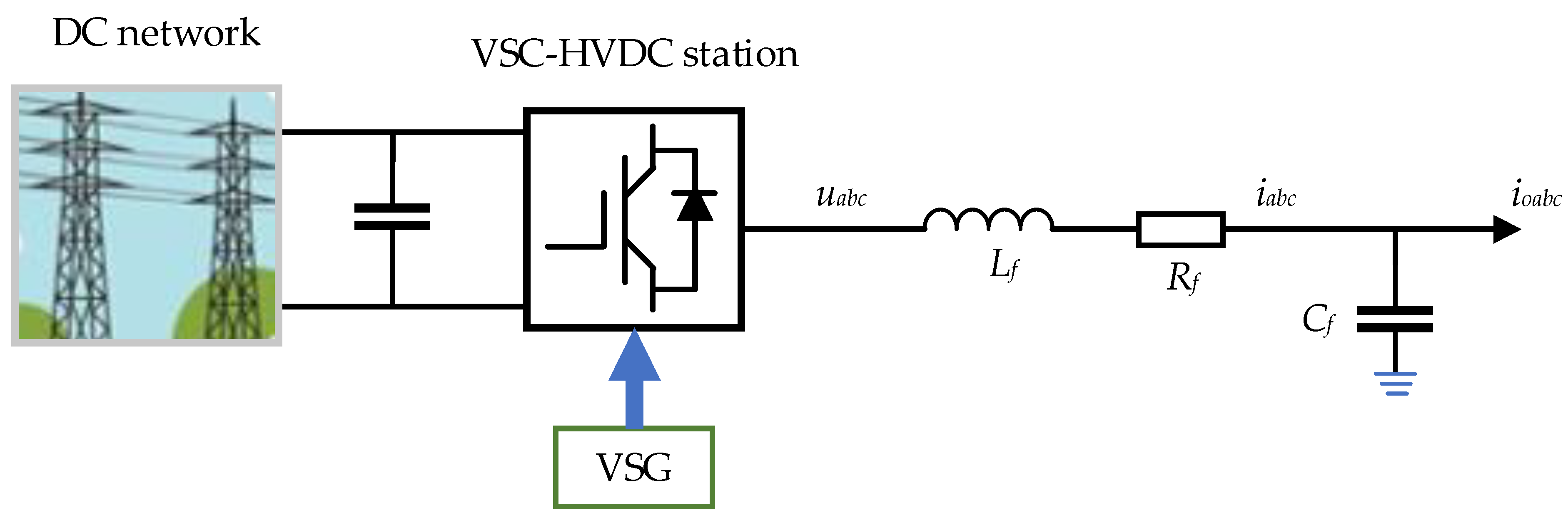
6.4. Application of VSG in VSC-HVDC

HVDC transmission has the advantages of long transmission distance, large transmission capacity, and small power loss. It is widely used in long-distance power transmission, cross-regional power grid interconnection, distributed energy integration, and other areas [105,106]. Compared with line commutated converter-based HVDC (LCC-HVDC), VSC-HVDC has the advantages of independent control of active and reactive power, fast and flexible response-ability, and large regulation capacity [107,108]. However, compared with AC systems dominated by SGs, VSC-HVDC systems with conventional control strategies cannot provide inertia for the grid [109]. It will lead to grid power unbalancing, making the grid unstable. To improve the frequency stability of the grid, the VSG control is proposed to be applied in VSC-HVDC systems as shown in Figure 20 [110]. In [110], to realize fast power tracking ability and high virtual inertia at same time, a two-degree control structure was proposed. The results show that the frequency support ability is significantly improved.
There are two major challenges when VSG is applied in VSC-MTDC systems [111,112]. The first is the oscillation issue, which results from the similar swing characteristic of SGs. The second is DC voltage instability. The virtual inertia is achieved by the integrator in the active power loop, which reduces the power regulation speed. Thus, the power deficiency in the DC network is hard to compensate in time and could further lead to a large DC voltage deviation after disturbances in DC network [111]. The damping torque analysis method is widely used for the small-signal stability analysis of the HVDC system. The influences of VSG on power system low-frequency oscillations using a damping torque analysis method were investigated in [112]. It is shown that the VSG can play a significant role in damping low-frequency oscillations of power grids with proper control. To further enhance the performance of the VSG-based HVDC system, a dual damping loop is proposed [113]. By the virtual governor and virtual rotational inertia, the power oscillations are reduced by the power redistribution among VSC stations. the DC-side resonance of multi-terminal VSC-HVDC is analyzed in [3]. The benefits of VSG in the stable operation of multi-terminal VSC-HVDC were demonstrated. The DC voltage is regulated by varying the voltage droop coefficients in [111]. The relationship between inertia and DC voltage is analyzed in [114]. It was pointed out that the increase in inertia reduces the stability margin of DC voltage. To achieve both fast power reference tracking ability for DC voltage regulation and high virtual inertia for frequency support, an approach based on a two-degrees-of-freedom control structure is proposed in [110].

7. Conclusions

The VSG technology combines the flexibility of power electronic equipment and the operation mechanism of SGs. The development of VSG can provide a convenient and economical solution to integrate renewable power generation sources into the grid.
This paper presents a deep analysis of the VSG operational principle and a comprehensive overview of the research status of all parts of VSG technology, including the ontology model, topologies, control strategies, energy supporting ways, and applications in the power grid. The existing problems of all parts are discussed. It would serve as a basic guideline to investigate further technological development and new applications of the VSG, and thus benefits the readers, researchers, engineers, and academicians who deal with the research works in the area of the VSG.

Author Contributions

Writing—original draft: W.S. and W.G.; writing—review and editing: S.D., C.T., S.Y. and Y.T. All authors have read and agreed to the published version of the manuscript.

Funding

This research was funded by National Natural Science Foundation of China, grant number 51877206.

Institutional Review Board Statement

Not applicable.

Informed Consent Statement

Not applicable.

Data Availability Statement

Not applicable.

Conflicts of Interest

The authors declare no conflict of interest.

References

  1. Haritha, M.; Divya, S. Review on Virtual Synchronous Generator (VSG) for Enhancing Performance of Microgrid. In Proceedings of the 2018 International Conference on Power, Signals, Control and Computation (EPSCICON), Thrissur, India, 6–10 January 2018. [Google Scholar]
  2. Vasudevan, K.R.; Ramachandaramurthy, V.K.; Babu, T.S. Synchronverter: A Comprehensive Review of Modifications, Stability Assessment, Applications and Future Perspectives. IEEE Access 2020, 8, 131565–131585. [Google Scholar] [CrossRef]
  3. Chen, M.; Zhou, D.; Blaabjerg, F. Modelling, Implementation, and Assessment of Virtual Synchronous Generator in Power Systems. J. Mod. Power Syst. Clean Energy 2019, 8, 399–411. [Google Scholar] [CrossRef]
  4. Zhong, Q.C. Virtual Synchronous Machines: A unified interface for grid integration. IEEE Power Electron. Mag. 2016, 3, 18–27. [Google Scholar] [CrossRef]
  5. Liu, J.; Yang, D.J.; Yao, W. PV-based virtual synchronous generator with variable inertia to enhance power system transient stability utilizing the energy storage system. Prot. Control Mod. Power Syst. 2017, 2, 39. [Google Scholar] [CrossRef]
  6. Zhong, Q.C.; Weiss, G. Synchronverters: Inverters That Mimic Synchronous Generators. IEEE Trans. Ind. Electron. 2010, 58, 1259–1267. [Google Scholar] [CrossRef]
  7. Li, J.; Wen, B.; Wang, H. Adaptive Virtual Inertia Control Strategy of VSG for Micro-Grid Based on Improved Bang-Bang Control Strategy. IEEE Access 2019, 7, 39509–39514. [Google Scholar] [CrossRef]
  8. Adapa, M.H.; Baker, L.; Bohmann, K.C. Proposed terms and definitions for flexible AC transmission system (FACTS). IEEE Trans. Power Deliv. 1997, 12, 1848–1853. [Google Scholar]
  9. Kechroud, A.; Myrzik, J.M.A.; Kling, W. Taking the experience from Flexible AC Transmission Systems to flexible AC distribution systems. In Proceedings of the 42nd International Universities Power Engineering Conference, Brighton, UK, 4–6 September 2007. [Google Scholar]
  10. Loix, T. Participation of Inverter-Connected Distributed Energy Resources in Grid Voltage Control; Katholieke Universiteit: Leuven, Belgium, 2011. [Google Scholar]
  11. Beck, H.-P.; Hesse, R. Virtual Synchronous Machine. In Proceedings of the 9th International Conference on Electrical Power Quality and Utilisation, Barcelona, Spain, 9–11 October 2007. [Google Scholar]
  12. Zhong, Q.C. Four-quadrant operation of AC machines powered by inverters that mimic synchronous generators. In Proceedings of the 5th IET International Conference on Power Electronics, Machines and Drives (PEMD 2010), Brighton, UK, 19–21 April 2010. [Google Scholar]
  13. Alatrash, H.; Mensah, A.; Mark, E.; Amarin, R.; Enslin, J. Generator Emulation Controls for Photovoltaic Inverters. In Proceedings of the 8th International Conference on Power Electronics—ECCE Asia, Jeju, Korea, 30 May–3 June 2011. [Google Scholar]
  14. Lin, Q.; Kanekiyo, Y.; Arai, J.; Yamashita, D. Field Demonstration of Parallel Operation of Virtual Synchronous Controlled Grid-Forming Inverters and a Diesel Synchronous Generator in a Microgrid. IEEE Access 2022, 10, 39095–39106. [Google Scholar] [CrossRef]
  15. Recommended Practice or Use and Functions of Virtual Synchronous Machines. Available online: http://standards.ieee.org/ieee/2988/10581 (accessed on 25 March 2021).
  16. Gao, F.; Iravani, M.R. A Control Strategy for a Distributed Generation Unit in Grid-Connected and Autonomous Modes of Operation. IEEE Trans. Power Deliv. 2008, 23, 850–859. [Google Scholar]
  17. Zhang, X.; Zhu, D.B.; Xu, H.Z. Review of Virtual Synchronous Generator Technology in Distributed Generation. J. Power Supply 2012, 3, 1–5. [Google Scholar]
  18. Fang, J.Y.; Zhang, R.Q.; Li, H.C.; Tang, Y. Frequency Derivative-Based Inertia Enhancement by Grid-Connected Power Converters with a Frequency-Locked-Loop. IEEE Trans. Smart Grid 2019, 5, 4918–4927. [Google Scholar] [CrossRef]
  19. Chen, Y.; Hesse, R.; Turschner, D.; Beck, H.P. Improving the grid power quality using virtual synchronous machines. In Proceedings of the 2011 International Conference on Power Engineering, Energy and Electrical Drives, Malaga, Spain, 11–13 May 2011. [Google Scholar]
  20. Li, Z.J.; Jia, X.Y.; Wang, L.J. Improved Virtual Synchronous Generator Based on Enhanced Inertiaand Damping Characteristics. Acta Energy Sol. Sin. 2021, 7, 79–84. [Google Scholar]
  21. Zhang, Y.; Yan, X. Coupling Analysis and Decoupling Control of Microgrid Power. Power Syst. Technol. 2016, 40, 813–818. [Google Scholar]
  22. Knap, V.; Sanjay, K.C.; Stroe, D.I. Sizing of an Energy Storage System for Grid Inertial Response and Primary Frequency Reserve. IEEE Trans. Power Syst. 2016, 31, 3447–3456. [Google Scholar] [CrossRef]
  23. Thongchart, K.; Fathin, R.; Yasunori, M. Virtual Inertia Control Application to Enhance Frequency Stability of Interconnected Power Systems with High Renewable Energy Penetration. Energies 2018, 11, 981. [Google Scholar]
  24. Lerch, K.S.; Kerdphol, T.; Mitani, Y.; Turschner, D. Frequency Stability Assessment on Virtual Inertia Control Strategy in Connected and Islanded Multi-Area Power Systems. In Proceedings of the 2020 IEEE International Conference on Environment and Electrical Engineering and 2020 IEEE Industrial and Commercial Power Systems Europe (EEEIC/I & CPS Europe), Madrid, Spain, 9–12 June 2020. [Google Scholar]
  25. Suul, J.A.; D’Arco, S.; Guidi, G. Virtual synchronous machine-based control of a single-phase bi-directional battery charger for providing vehicle-to-grid services. IEEE Trans. Ind. Appl. 2016, 52, 3234–3244. [Google Scholar] [CrossRef] [Green Version]
  26. Liu, J.; Miura, Y.; Bevrani, H.; Ise, T. Enhanced Virtual Synchronous Generator Control for Parallel Inverters in Microgrids. IEEE Trans. Smart Grid 2017, 8, 2268–2277. [Google Scholar] [CrossRef]
  27. Wu, W.H.; Zhou, L.M.; Chen, Y.D. Sequence-Impedance-Based Stability Comparison between VSGs and Traditional Grid-Connected Inverters. IEEE Trans. Power Electron. 2019, 1, 46–52. [Google Scholar] [CrossRef]
  28. Aghazadeh, A.; Khodabakhshi-Javinani, N.; Nafisi, H. Adapted Near-State PWM for Dual 2L Inverter for Reducing Common-Mode Voltage and Switching Losses. IET Power Electron. 2019, 12, 676–685. [Google Scholar] [CrossRef]
  29. Grogan, S.A.S.; Holmes, D.G. High-Performance Voltage Regulation of Current Source Inverters. IEEE Trans. Power Electron. 2011, 26, 2439–2448. [Google Scholar] [CrossRef]
  30. Su, G.J.; Ning, P.Q. Loss Modeling and Comparison on VSI and RB-IGBT Based CSI in Traction Drive Applications. In Proceedings of the 2013 IEEE Transportation Electrification Conference and Expo (ITEC), Detroit, MI, USA, 16–19 June 2013. [Google Scholar]
  31. Torres, M.; Baier, C.; Juan, M. Non-Linear Control of a Grid-Connected Multi-Cell Photovoltaic Inverter that Operates under Variable Temperature and Irradiance. In Proceedings of the 2015 IEEE International Conference on Industrial Technology (ICIT), Seville, Spain, 17–19 March 2015. [Google Scholar]
  32. Dashtaki, M.A.; Nafisi, H.; Pouresmaeil, E.; Khorsandi, A. Virtual Inertia Implementation in Dual Two-Level Voltage Source Inverters. In Proceedings of the 2020 11th Power Electronics, Drive Systems, and Technologies Conference (PEDSTC), Tehran, Iran, 4–6 February 2020. [Google Scholar]
  33. Dupczak, B.S.; Perin, A.J.; Heldwein, M.L. Space vector modulation strategy applied to interphase transformers-based five-level current source inverters. IEEE Trans. Power Electron. 2012, 27, 2740–2751. [Google Scholar] [CrossRef]
  34. Pouresmaeil, M.; Sepehr, A.; Sangrody, R.; Taheri, S. Control of Multilevel Converters for High Penetration of Renewable Energies. In Proceedings of the 2021 IEEE 12th International Symposium on Power Electronics for Distributed Generation Systems (PEDG), Chicago, IL, USA, 28 June–1 July 2021. [Google Scholar]
  35. Yu, Y.; Gao, H.Y.; Guo, Q.B. Cascaded 3-Phase-Bridge Converter Based on Virtual Synchronous Generator Control. In Proceedings of the IECON 2021—47th Annual Conference of the IEEE Industrial Electronics Society, Toronto, ON, Canada, 13–16 October 2021. [Google Scholar]
  36. Chen, J.K.; Zeng, Q.; Li, G.Q.; Xin, Y.C. Deviation-Free Frequency Control of MMC-MTDC Converter Based on Improved VSG. In Proceedings of the 2019 IEEE 10th International Symposium on Power Electronics for Distributed Generation Systems (PEDG), Xiamen, China, 11–14 November 2019. [Google Scholar]
  37. Chen, J.K.; Zeng, Q.; Li, G.Q. A Coordination Control Method for Multi-terminal AC/DC Hybrid System Based on MMC Transmission Technology. In Proceedings of the 2019 IEEE 10th International Symposium on Power Electronics for Distributed Generation Systems (PEDG), Xi’an, China, 3–6 June 2019. [Google Scholar]
  38. Chen, D.; Xu, Y.Z.; Huang, A.Q. Integration of DC Microgrids as Virtual Synchronous Machines into the AC Grid. IEEE Trans. Ind. Electron. 2017, 64, 7455–7466. [Google Scholar] [CrossRef]
  39. Wang, Z.X.; Hao, Y.; Fang, Z. A Hardware Structure of Virtual Synchronous Generator in Photovoltaic Microgrid and Its Dynamic Performance Analysis. Proc. CSEE 2017, 37, 444–453. [Google Scholar]
  40. Shi, H.T.; Zhuo, F.; Yi, H.; Wang, F. A Novel Real-Time Voltage and Frequency Compensation Strategy for Photovoltaic-Based Microgrid. IEEE Trans. Ind. Electron. 2015, 62, 3545–3556. [Google Scholar] [CrossRef]
  41. Othman, M.H.; Mokhlis, H.; Mubin, M.; Talpur, S. Progress in control and coordination of energy storage system-based VSG: A review. IET Renew. Power Gener. 2020, 14, 177–187. [Google Scholar] [CrossRef]
  42. Shintai, T.; Miura, Y.; Ise, T. Oscillation damping of a distributed generator using a virtual synchronous generator. IEEE Trans. Power Deliv. 2014, 29, 668–676. [Google Scholar] [CrossRef]
  43. Guan, M.Y.; Pan, W.L.; Zhang, J.; Hao, Q.R. Synchronous Generator Emulation Control Strategy for Voltage Source Converter (VSC) Stations. IEEE Trans. Power Syst. 2015, 30, 3093–3101. [Google Scholar] [CrossRef]
  44. Li, M.X.; Wang, Y.; Xu, N.Y.; Wang, W.T. A Consistent Dynamic Response Control Strategy for Virtual Synchronous Generator. In Proceedings of the 2017 IEEE 3rd International Future Energy Electronics Conference and ECCE Asia (IFEEC 2017—ECCE Asia), Kaohsiung, Taiwan, 3–7 June 2017. [Google Scholar]
  45. Alipoor, J.; Miura, Y.; Ise, T. Power System Stabilization Using Virtual Synchronous Generator with Alternating Moment of Inertia. IEEE J. Emerg. Sel. Top. Power Electron. 2015, 3, 451–458. [Google Scholar] [CrossRef]
  46. Li, D.D.; Zhu, Q.W.; Lin, S.F. A self-adaptive inertia and damping combination control of VSG to support frequency stability. IEEE Trans. Energy Convers. 2017, 32, 397–398. [Google Scholar] [CrossRef]
  47. Meng, J.H.; Wang, Y.; Fu, C.; Wang, H. Adaptive Virtual Inertia Control of Distributed Generator for Dynamic Frequency Support in Microgrid. In Proceedings of the 2016 IEEE Energy Conversion Congress and Exposition (ECCE), Milwaukee, WI, USA, 18–22 September 2016. [Google Scholar]
  48. Song, Q.; Zhang, H.; Sun, K.; Wei, Y. Improved Adaptive Control of Inertia for Virtual Synchronous Generators in Islanding Micro-grid with Multiple Distributed Generation Units. Proc. CSEE 2017, 20, 413–423. [Google Scholar]
  49. Wu, H.; Wang, X.F. A Mode-Adaptive Power-Angle Control Method for Transient Stability Enhancement of Virtual Synchronous Generators. IEEE J. Emerg. Sel. Top. Power Electron. 2020, 8, 1034–1049. [Google Scholar] [CrossRef]
  50. Sun, L.Y.; Wang, P.C.; Han, J.F.; Wang, Y.Q. Adaptive Inertia Control of Virtual Synchronous Generator Based on Power Feedback. In Proceedings of the 2021 IEEE 4th International Electrical and Energy Conference (CIEEC), Wuhan, China, 28–30 May 2021. [Google Scholar]
  51. Quan, X.J.; Yu, R.Y.; Zhao, X.; Lei, Y. Photovoltaic Synchronous Generator (PVSG): Architecture and Control Strategy for a Grid-Forming PV Energy System. IEEE J. Emerg. Sel. Top. Power Electron. 2020, 8, 936–948. [Google Scholar] [CrossRef]
  52. Jiang, K.; Su, H.S.; Lin, H.J.; He, K.Z. A Practical Secondary Frequency Control Strategy for Virtual Synchronous Generator. IEEE Trans. Smart Grid 2020, 11, 2734–2736. [Google Scholar] [CrossRef]
  53. Li, M.X.; Yu, P.; Hu, W.H.; Wang, Y. Phase Feedforward Damping Control Method for Virtual Synchronous Generators. IEEE Trans. Power Electron. 2022, 37, 9790–9806. [Google Scholar] [CrossRef]
  54. Tiwari, A.K.; Seethalekshmi, K. Adaptive Virtual Synchronous Generator Control for Grid Forming Inverters in Islanded AC Microgrid—A Real Time Simulation. In Proceedings of the 2021 International Conference on Control, Automation, Power and Signal Processing (CAPS), Jabalpur, India, 10–12 December 2021. [Google Scholar]
  55. D’Arcoa, S.; Suul, J.A.; Fosso, B.O. Small-signal modeling and parametric sensitivity of a virtual synchronous machine in islanded operation. Electr. Power Energy Syst. 2015, 3, 4–13. [Google Scholar] [CrossRef]
  56. Chen, M.; Zhou, D.; Blaabjerg, F. Voltage Control Impact on Performance of Virtual Synchronous Generator. In Proceedings of the 2021 IEEE 12th Energy Conversion Congress & Exposition—Asia (ECCE—Asia), Singapore, 24–27 May 2021. [Google Scholar]
  57. Li, Y.W.; Kao, C.N. An accurate power control strategy for Power Electronics-Interfaced distributed generation units operating in a low voltage multi-bus microgrid. IEEE Trans. Power Electron. 2009, 24, 2977–2988. [Google Scholar]
  58. Mo, O.; D’Arco, S.; Suul, J.A. Evaluation of virtual synchronous machines with dynamic or quasi-stationary machine models. IEEE Trans. Ind. Electron. 2017, 64, 5952–5962. [Google Scholar] [CrossRef]
  59. Wu, H.; Ruan, X.B.; Yang, D.S.; Chen, X.R. Small-Signal Modeling and Parameters Design for Virtual Synchronous Generators. IEEE Trans. Ind. Electron. 2016, 63, 4292–4303. [Google Scholar] [CrossRef]
  60. Zhang, Q.Q.; Wai, R.J. Robust power sharing and voltage stabilization control structure via sliding-mode technique in islanded micro-grid. Energies 2021, 14, 883. [Google Scholar] [CrossRef]
  61. Hu, Y.W.; Shao, Y.T.; Yang, R.C. A Configurable Virtual Impedance Method for Grid-Connected Virtual Synchronous Generator to Improve the Quality of Output Current. IEEE J. Emerg. Sel. Top. Power Electron. 2020, 3, 2404–2417. [Google Scholar] [CrossRef]
  62. Wen, T.L.; Zhu, D.H.; Zou, X.D.; Jiang, B.C. Power coupling mechanism analysis and improved decoupling control for virtual synchronous generator. IEEE Trans. Power Electron. 2021, 36, 3028–3041. [Google Scholar] [CrossRef]
  63. Wang, Y.; Wai, R.J. Adaptive Fuzzy-Neural-Network Power Decoupling Strategy for Virtual Synchronous Generator in Micro-Grid. IEEE Trans. Power Electron. 2022, 37, 3878–3891. [Google Scholar] [CrossRef]
  64. Charalambous, A.; Hadjidemetriou, L.; Kyriakides, E. A Coordinated Voltage–Frequency Support Scheme for Storage Systems Connected to Distribution Grids. IEEE Trans. Power Electron. 2021, 36, 8464–8475. [Google Scholar] [CrossRef]
  65. Zhang, H.; Zhang, X.; Li, M.; Guan, W.; Zhao, W. A Photovoltaic Virtual Synchronous Generator Control Strategy Based on Active Power Reserve. Power Syst. Technol. 2019, 43, 515–519. [Google Scholar]
  66. Tang, W.B.; Xiao, L.Y.; Shi, L.M.; Wang, Z. Research on the Principle and Structure of a New Energy Storage Technology Named Vacuum Pipeline Maglev Energy Storage. IEEE Access 2020, 8, 89351–89366. [Google Scholar] [CrossRef]
  67. Nikolaidis, P.; Poullikkas, A. Cost metrics of electrical energy storage technologies in potential power system operations. Sustain. Energy Technol. Assess. 2018, 25, 43–59. [Google Scholar] [CrossRef]
  68. Superconducting Magnetic Energy Storage (SMES) System. Available online: https://www.researchgate.net/publication/261204920 (accessed on 11 July 2015).
  69. Guo, W.Y.; Cai, F.Y.; Zhao, C.; Zhang, J.Y. Application and Prospect of Superconducting Magnetic Energy Storage for Renewable Energy. Autom. Electr. Power Syst. 2019, 43, 1–10. [Google Scholar]
  70. Ngamroo, I. Robust decentralized frequency stabilizers design for SMES taking into consideration system uncertainties. Electr. Power Syst. Res. 2005, 74, 281–292. [Google Scholar] [CrossRef]
  71. Guo, W.Y. Optimal Power Smoothing Control for Superconducting Fault Current Limiter-Magnetic Energy Storage System. Cryogenics 2021, 116, 103296. [Google Scholar] [CrossRef]
  72. Linn, Z. Power System Stabilization Control by HVDC with SMES Using Virtual Synchronous Generator. IEEJ J. Ind. Appl. 2012, 1, 102–110. [Google Scholar] [CrossRef]
  73. You, D.J.; Jang, S.M.; Lee, J.P.; Sung, T.H. Dynamic Performance Estimation of High-Power FESS Using the Operating Torque of a PM Synchronous Motor/Generator. IEEE Trans. Magn. 2008, 44, 4155–4158. [Google Scholar]
  74. Faraji, F.; Majazi, A.; Al-Haddad, K. A comprehensive review of Flywheel Energy Storage System technology. Renew. Sustain. Energy Rev. 2017, 67, 477–490. [Google Scholar]
  75. Yu, J.L.; Fang, J.Y.; Tang, Y. Inertia Emulation by Flywheel Energy Storage Systems for Improved Frequency Regulation. In Proceedings of the 2018 IEEE 4th Southern Power Electronics Conference (SPEC), Singapore, 10–13 December 2018. [Google Scholar]
  76. Yonghui1, N.; Zhang, L.L.; Zhang, L.D.; Gao, L. A VSG-Based Coordinated Control Method for Wind Turbine and Flywheel Energy Storage. Acta Energy Sol. Sin. 2021, 42, 388–392. [Google Scholar]
  77. Zhang, R.Q.; Fang, J.Y.; Tang, Y. Inertia Emulation through Supercapacitor Energy Storage Systems. In Proceedings of the 2019 10th International Conference on Power Electronics and ECCE Asia (ICPE 2019—ECCE Asia), Busan, Korea, 27–30 May 2019. [Google Scholar]
  78. Chen, L.; Blaabjerg, F. Virtual Synchronous Generator Based on Type-IV Wind Turbine with Supercapacitor as Storage. In Proceedings of the 2021 IEEE/IAS Industrial and Commercial Power System Asia (I & CPS Asia), Chengdu, China, 18–21 July 2021. [Google Scholar]
  79. Paucara, J.D.; Peña, J.C.U.; Rosas, D.S.Y. Control Strategy to Provide Frequency Support Functionality Using a Supercapacitor-Based Energy Storage System. In Proceedings of the 2021 IEEE Vehicle Power and Propulsion Conference (VPPC), Gijon, Spain, 25–28 October 2021. [Google Scholar]
  80. Xu, H.F.; Wang, Y.; Liu, H.; Yang, P. A Capacitor Inertia Based VSG and the Stability Analysis. In Proceedings of the 2021 4th International Conference on Energy, Electrical and Power Engineering (CEEPE), Chongqing, China, 23–25 April 2021. [Google Scholar]
  81. Liu, Y.H.; Wang, Y.; Wang, M.H.; Xu, Z. Coordinated VSG Control of Photovoltaic/Battery System for Maximum Power Output and Grid Supporting. IEEE J. Emerg. Sel. Top. Circuits Syst. 2022, 12, 301–309. [Google Scholar] [CrossRef]
  82. Fang, J.Y.; Li, X.O.; Tang, Y. Power management of virtual synchronous generators through using hybrid energy storage systems. In Proceedings of the 2018 IEEE Applied Power Electronics Conference and Exposition (APEC), San Antonio, TX, USA, 4–8 March 2018. [Google Scholar]
  83. Jain, A.; Padhy, N.P.; Pathak, M.K. Quantification of inertia contribution from non-conventional sources in AC microgrid. In Proceedings of the 2022 IEEE International Conference on Power Electronics, Smart Grid, and Renewable Energy (PESGRE), Trivandrum, India, 2–5 January 2022. [Google Scholar]
  84. Abeywardana, D.B.W.; Hredzak, B. Supercapacitor sizing method for energy-controlled filter-based hybrid energy storage system. IEEE Trans. Power Electron. 2017, 32, 1626–1637. [Google Scholar] [CrossRef]
  85. Fang, J.; Tang, Y.; Li, H.; Li, X. A Battery/Ultracapacitor Hybrid Energy Storage System for Implementing the Power Management of Virtual Synchronous Generators. IEEE Trans. Power Electron. 2018, 33, 2820–2824. [Google Scholar] [CrossRef]
  86. Verdugo, C.; Tarraso, A.; Candela, J.I.; Rocabert, J. Centralized Synchronous Controller Based on Load Angle Regulation for Photovoltaic Power Plants. IEEE J. Emerg. Sel. Top. Power Electron. 2021, 9, 485–496. [Google Scholar] [CrossRef]
  87. Wang, D.; Wu, H. Application of Virtual Synchronous Generator Technology in Microgrid. In Proceedings of the 2016 IEEE 8th International Power Electronics and Motion Control Conference (IPEMC-ECCE Asia), Hefei, China, 22–26 May 2016. [Google Scholar]
  88. Zheng, T.; Chen, L.; Liu, W.; Guo, Y. Multi-mode Operation Control for Photovoltaic Virtual Synchronous Generator Considering the Dynamic Characteristics of Primary Source. Proc. CSEE 2017, 37, 454–463. [Google Scholar]
  89. Islam, K.; Mannan, M.A.; Hazari, R. Virtual Synchronous Generator Control of Stand-Alone PV Station to Enhance Voltage Stability. In Proceedings of the 2021 IEEE Region 10 Symposium (TENSYMP), Jeju, Korea, 23–25 August 2021. [Google Scholar]
  90. Xiaolin, Z.; Wei, D.; Guanzxiu, Y. Test Method for Inertia and Damping of Photovoltaic Virtual Synchronous Generator Based on Power Angle Transfer Function. In Proceedings of the 2018 2nd IEEE Conference on Energy Internet and Energy System Integration (EI2), Beijing, China, 20–22 October 2018. [Google Scholar]
  91. Zhang, X.; Li, M.; Guo, Z.; Wang, J.; Han, F. Review and Perspectives on Control Strategies for Renewable Energy Grid-connected Inverters. J. Glob. Energy Interconnect. 2021, 4, 507–512. [Google Scholar]
  92. Ma, Y.; Cao, W.; Yang, L.; Wang, F. Virtual Synchronous Generator Control of Full Converter Wind Turbines with Short-Term Energy Storage. IEEE Trans. Ind. Electron. 2017, 64, 8821–8831. [Google Scholar] [CrossRef]
  93. Liserre, M.; Cárdenas, R.; Molinas, M.; Rodriguez, J. Overview of multi-MW wind turbines and wind parks. IEEE Trans. Ind. Electron. 2011, 58, 1081–1095. [Google Scholar] [CrossRef]
  94. Zhao, Y.; Liu, L.; Wang, L. Virtual Synchronous Grid Interface of Distributed Wind Turbines without PLL. In Proceedings of the 2021 IEEE Sustainable Power and Energy Conference (iSPEC), Nanjing, China, 23–25 December 2021. [Google Scholar]
  95. Liu, X.; Xu, Z.; Jian, Z. Combined primary frequency control strategy of permanent magnet synchronous generator-based wind turbine. Electr. Power Compon. Syst. 2019, 46, 1704–1718. [Google Scholar] [CrossRef]
  96. Li, Y.; Xu, Z.; Zhang, J.; Wong, K.P. Variable gain control scheme of DFIG-based wind farm for over-frequency support. Renew. Energy 2018, 120, 379–391. [Google Scholar] [CrossRef]
  97. Arani, M.F.M.; El-Saadany, E.F. Implementing virtual inertia in DFIG-Based Wind power generation. IEEE Trans. Power Syst. 2013, 28, 1373–1384. [Google Scholar] [CrossRef]
  98. Zeng, X.; Liu, T.; Wang, S.; Dong, Y.; Chen, Z. Comprehensive coordinated control strategy of PMSG-based wind turbine for providing frequency regulation services. IEEE Access 2019, 7, 63944–63953. [Google Scholar] [CrossRef]
  99. Jiang, Q.; Zeng, X.; Li, B.; Wang, S. Time-Sharing Frequency Coordinated Control Strategy for PMSG-Based Wind Turbine. IEEE J. Emerg. Sel. Top. Circuits Syst. 2022, 12, 268–278. [Google Scholar] [CrossRef]
  100. Yue, M. Grid Inertial Response-Based Probabilistic Determination of Energy Storage System Capacity under High Solar Penetration. In Proceedings of the 2015 IEEE Power & Energy Society General Meeting, Denver, CO, USA, 26–30 July 2015. [Google Scholar]
  101. Bera, A.; Abdelmalak, M.; Alzahrani, S.; Benidris, M. Sizing of Energy Storage Systems for Grid Inertial Response. In Proceedings of the 2020 IEEE Power & Energy Society General Meeting (PESGM), Montreal, QC, Canada, 2–6 August 2020. [Google Scholar]
  102. Li, Z.; Zhang, Z.; He, T.; Song, P. Research on Harmonic Resonance Mechanism and Inhibition Strategy of LC Type Energy Storage Virtual Synchronous Generator. In Proceedings of the 2018 International Conference on Power System Technology (POWERCON), Guangzhou, China, 6–8 November 2018. [Google Scholar]
  103. Xu, J.; Xie, S.; Xiao, H. Research on Control Mechanism of Active Damping for LCL Filters. Proc. CSEE 2012, 32, 27–33. [Google Scholar]
  104. Chen, X.; Wei, Z.; Hu, X.; Cen, Y.; Gong, C. Research on LCL Filter in Three-Phase Grid-Connected Inverter and Novel Active Damping Control Strategy. Trans. China Electrotech. Soc. 2014, 29, 72–77. [Google Scholar]
  105. Long, W.; Nilsson, S. HVDC transmission: Yesterday and today. IEEE Power Energy Mag. 2007, 5, 22–31. [Google Scholar] [CrossRef]
  106. Farshad, M.; Sadeh, J. A Novel Fault-Location Method for HVDC Transmission Lines Based on Similarity Measure of Voltage Signals. IEEE Trans. Power Deliv. 2013, 28, 2483–2490. [Google Scholar] [CrossRef]
  107. Fuchs, A.; Imhof, M.; Demiray, T.; Morar, M. Stabilization of Large Power Systems Using VSC̢HVDC and Model Predictive Control. In Proceedings of the 2016 IEEE Power and Energy Society General Meeting (PESGM), Boston, MA, USA, 17–21 July 2016. [Google Scholar]
  108. Shen, Y.; Chen, W.; Yao, W.; Liao, S. Supplementary damping control of VSC-HVDC for interarea oscillation using goal representation heuristic dynamic programming. In Proceedings of the 12th IET International Conference on AC and DC Power Transmission (ACDC 2016), Beijing, China, 28–29 May 2016. [Google Scholar]
  109. Liu, X.; Sun, P.; Arraño-Vargas, F.; Konstantinou, G. Provision of Synthetic Inertia by Alternate Arm Converters in VSC-HVDC Systems. In Proceedings of the 2021 31st Australasian Universities Power Engineering Conference (AUPEC), Perth, Australia, 26–30 September 2021. [Google Scholar]
  110. Leon, A.E.; Mauricio, J.M. Virtual Synchronous Generator for VSC-HVDC Stations with DC Voltage Control. IEEE Trans. Power Syst. 2022, 1–1. [Google Scholar] [CrossRef]
  111. Wang, W.; Jiang, L.; Cao, Y.; Li, Y. A Parameter Alternating VSG Controller of VSC-MTDC Systems for Low Frequency Oscillation Damping. IEEE Trans. Power Syst. 2020, 35, 4609–4621. [Google Scholar] [CrossRef]
  112. Huang, L.; Xin, H.; Wang, Z. Damping Low-Frequency Oscillations through VSC-HVdc Stations Operated as Virtual Synchronous Machines. IEEE Trans. Power Electron. 2019, 34, 5803–5818. [Google Scholar] [CrossRef]
  113. Pérez, J.R.; Suul, J.A.; D’Arco, S.; Rodríguez-Cabero, A. Virtual synchronous machine control of vsc hvdc for power system oscillation damping. In Proceedings of the IECON 2018—44th Annual Conference of the IEEE Industrial Electronics Society, Washington, DC, USA, 21–23 October 2018. [Google Scholar]
  114. Huang, L.; Xin, H.; Yang, H.; Wang, Z. Interconnecting very weak AC systems by multiterminal VSC-HVDC links with a unified virtual synchronous control. IEEE J. Emerg. Sel. Top. Power Electron. 2018, 6, 1041–1053. [Google Scholar] [CrossRef]
Figure 1. Circuit diagram of the grid-connected inverter.
Energies 15 06148 g001
Figure 2. Block diagram of control principle. (a) Block diagram of the proposed frequency control. (b) Block diagram of voltage control.
Energies 15 06148 g002
Figure 3. Block diagram of the control principle.
Energies 15 06148 g003
Figure 4. The control structure of VISMA.
Energies 15 06148 g004
Figure 5. The types of grid-connected inverters.
Energies 15 06148 g005
Figure 6. (a) Typical topology of three-phase VSI; (b) Typical topology of three-phase CSI.
Energies 15 06148 g006
Figure 7. (a) The topology diagram of three-phase active NPC. (b) The topology diagram of MMC.
Energies 15 06148 g007
Figure 8. Power conversion stage of VSG (a) Single-stage structure; (b) dual stage structure.
Energies 15 06148 g008
Figure 9. Energy storage VSG. (a) Single-stage common DC bus VSG; (b) Dual-stage common DC bus VSG; (c) Single-stage common AC bus VSG; (d) Dual-stage common AC bus VSG.
Energies 15 06148 g009
Figure 10. (a) feedback modes of the power-angle control of the VSG; (b) Block diagram of mode-adaptive control of the VSG.
Energies 15 06148 g010
Figure 11. Active power control link of VSG with power feedback.
Energies 15 06148 g011
Figure 12. Block diagram of VSG using phase feedforward damping control.
Energies 15 06148 g012
Figure 13. Q-droop control.
Energies 15 06148 g013
Figure 14. Droop-I control.
Energies 15 06148 g014
Figure 15. The control reactive power and voltage.
Energies 15 06148 g015
Figure 16. (a) Virtual impedance control; (b) Fundamental equivalent circuit.
Energies 15 06148 g016
Figure 17. Applications of VSG in power systems.
Energies 15 06148 g017
Figure 18. Schematic diagram of PVSG.
Energies 15 06148 g018
Figure 19. Schematic diagram of wind power generation VSG.
Energies 15 06148 g019
Figure 20. Schematic diagram of VSC-HVDC with VSG.
Energies 15 06148 g020
Table 1. Comparison of current-controlled VSG and voltage-controlled VSG.
VSG TypeSubtypeAdvantagesDisadvantages
CC-VSGBasic CC-VSG [10]
  • The active and reactive power are decoupled;
  • Fast current response;
  • with current limiting capability;
  • Without grid forming ability.
  • Weak stability under an ultraweak grid or with multiple inverters condition due to PLL [27].
VISMA [19]
  • Fast current response;
  • Stability uninfluenced by the PLL [27].
  • Without grid forming ability.
  • The excitation control of SGs is not simulated.
VC-VSGBasic VC-VSG [16]
  • Fast frequency response;
  • Providing a smooth transition between grid-connected and autonomous modes
  • Without current limiting capability.
Synchronverter [6]
  • The electromagnetic characteristics of SG are more explicitly simulated compared with basic VC-VSG;
  • Fast frequency response;
  • Complex and uneasy to apply;
  • Weak anti-interference ability due to voltage open-loop control;
  • Active and reactive power control are coupled.
Table 2. The comparison of performance and structure between VSI and CSI.
Category VSICSI
DC link energy storage device CapacitorInductor
Output form square wave High-frequency voltage square wave High-frequency current
Diode positionAntiparallelSeries
Output voltage characteristicsBuckBoost
Table 3. Power oscillation modes.
Δw d w / d t ModeAlternating J
Δ w > 0 d w / d t > 0AcceleratingBig value of J
Δ w > 0 d w / d t < 0DeceleratingSmall value of J
Δ w < 0 d w / d t < 0AcceleratingBig value of J
Δ w < 0 d w / d t > 0DeceleratingSmall value of J
Table 4. The comparison of power reserve and energy storage.
CharactersEnergy StoragePower Reservation
Investment costhighlow
RES power generation efficiencyhighlow
Weather dependencylowhigh
Control difficultylowhigh
Table 5. The difference between inertia support and primary frequency regulation.
ObjectFunctional LocalizationRequirements to ESDs
Inertia supportSlowing down the rate of change in frequency.Fast power response;
High power requirement;
Low energy requirement.
Primary frequency regulationProviding continuous active power support in response to the frequency deviation of the grid.Slow power response;
Low power requirement;
High energy requirement.
Table 6. Summary of technical characteristic of typical energy storage [66].
The Type of Energy StorageSupercapacitor Energy
Storage
Flywheel Energy StorageLithium Battery Energy
Storage
Superconducting Magnetic
Energy Storage
Power capability (MW)0.05–0.10.1–200.015–501–10
Efficiency (%)65–8085–9690–95>95
Cost (¥/kWh)1500–2000400–800260–8001000–7000
Life time500 k times>15 years3–15 k times>30 years
Power density800–11,000 W/kg5000–11,900 W/kg150–2000 W/kg500–2000 W/kg [67]
Energy density1–8 Wh/kg5–100 Wh/kg80–150 Wh/kg1–10 Wh/kg
Response time<1 millisecond<2 millisecond<100 millisecond<2 millisecond
Charge time SecondMinute Hour Second
Technical maturityCommercial applicationDemonstration to Commercial applicationCommercial applicationDemonstration
Publisher’s Note: MDPI stays neutral with regard to jurisdictional claims in published maps and institutional affiliations.

