Article

Dynamic Characteristics and Demonstration of an Integrated Linear Engine Generator with Alternative Electrical Machines

1
School of Engineering, Newcastle University, Newcastle upon Tyne NE1 7RU, UK
2
Department of Electrical Engineering, College of Engineering, University of Baghdad, Baghdad 10001, Iraq
3
Department of Mechanical Engineering, University of Birmingham, Birmingham B15 2TT, UK
*
Author to whom correspondence should be addressed.
Energies 2022, 15(14), 5295; https://doi.org/10.3390/en15145295
Submission received: 9 June 2022 / Revised: 11 July 2022 / Accepted: 15 July 2022 / Published: 21 July 2022
(This article belongs to the Section F: Electrical Engineering)

Abstract

:
A linear engine generator with a compact double-acting free piston mechanism allows for full integration of the combustion engine and generator, which provides an alternative chemical-to-electrical energy converter with a higher volumetric power density for the electrification of automobiles, trains, and ships. This paper aims to analyse the performance of the integrated engine with alternative permanent magnet linear tubular electrical machine topologies using a coupled dynamic model in Siemens Simcenter software. Two types of alternative generator configurations are compared, namely long translator-short stator and short translator-long stator linear machines. The dynamic models of the linear engine and linear generator, validated with lab-scale prototypes, are applied to investigate the influence of alternative topologies of the generator on system performance. The coupled model will facilitate the early design phase and reveal the optimal match of the key parameters of the engine and generator. Then, experimental tests on an integrated compressor cylinder-generator prototype were successfully performed, and it is shown that this concept is feasible and electrical power and compressed working fluid, such as air, can be generated by this prototype.

Graphical Abstract

1. Introduction

A Linear Engine Generator (LEG) is a special type of combustion engine that represents a new approach concerning the conversion of chemical energy into electrical energy directly without a crank mechanism. Instead of using conventional engines, LEG hires a linear engine and linear generator to generate electricity directly with the linear movement of the piston-translator. The direct drive technology of a linear electrical machine is a perfect way to enhance power density and dynamic performance. Linear machines eliminate the need for mechanical transmissions. Thus, it dramatically reduces the volume, weight, friction, and complexity of a power generation system. The LEG’s efficiency is estimated to be higher than the efficiency of other systems, such as diesel generators, as shown in Figure 1, implying that using a LEG should increase the total system efficiency [1,2].
LEG is a potential alternative power supply in hybrid powertrains. The proposed hybrid electric system configuration is illustrated in Figure 2, which shows an example of using the LEG concept in an automotive application to propel electric motors and has been embedded into the tires of the vehicle. Alternatively, LEG can be developed as a range-extending device in electric vehicles to work as a battery charger.
From 1999 to 2003, Sandia National Laboratories [3,4] studied a type of Free Piston Engine Generator (FPEG) with a numerically homogeneous charge compression ignition combustion in terms of a previous FPEG prototype developed in 1998 [5]. West Virginia University studied a two-stroke FPEG numerically [6] and an experimental study was carried out with a power output of up to 316 W [7]. In 2008, Roskilly et al. [8] at Newcastle University simulated the performance of a spark ignition FPEG. A FPEG system was developed as a range-extending device in electric vehicles at the German Aerospace Center in 2012. The FPEG works at 21 Hz with a measured power output of 10 kW [9]. In 2014, Toyota developed a two-stroke FPEG prototype with a gas spring chamber, which demonstrated 42% thermal efficiency, and 10 kW could be achieved [10,11]. In 2020, the same research team from Newcastle University [12] reported a preliminary prototype of a hydrogen-fueled FPEG with a compression ratio of 3.7, engine speed between 5 Hz and 11 Hz, and different equivalence ratios.
With the increasing pressure of de-carbonization in transport sectors, hydrogen and ammonia are viewed as promising zero carbon fuels. The internal combustion of hydrogen and ammonia in a well-controlled manner poses difficulties on FPEGs that use conventional internal combustion engines. Researchers from Newcastle University proposed an external combustion Linear Joule Engine Generator (LJEG), and a working prototype has been developed with a 4.47-kW mechanical power output when the efficiency was 32.2% [13]. Wu et al. [14] presented a coupled dynamic model of a linear joule cycle engine generator, which enabled an integrated design of a linear engine and linear generator. Jia et al. [15] conducted a modeling study on the dynamic and thermodynamic characteristics of a LJEG and found that the system pressure was the most effective parameter to alter the system power output. Ngwaka et al. [16] built a numerical model of the friction forces and it was validated by experiments using a compressed air driven linear engine prototype. More recently, Ngwaka et al. proposed a closed-loop LEG concept with Argon-Hydrogen-Oxy external combustion to tackle the challenge of using zero carbon fuels in LEGs. Both external combustion and internal combustion engines may find their applications in the electrification and de-carbonization of transport sectors.
The research teams at Newcastle University have developed a linear engine prototype and a linear electrical machine prototype to validate the dynamic models before a coupled model is developed, respectively. The dynamic characteristic of the coupled system is defined by four interlinks, namely engine design, engine performance, electric machine design, and electric load.
This paper is to address the potential impact caused by the topologies of alternative Permanent Magnet (PM) generators on the performance of the LEG system. The structure of the paper is as follows. In Section 2, linear engine generators have been proposed. In Section 3, a coupled dynamic system of LEG has been investigated. In Section 4, performance validation has been carried out for the integrated system. Section 5 and Section 6 give the simulation and experimental results of the proposed integrated linear engine generators. Lastly, the paper has been concluded in Section 7 with a brief summary.

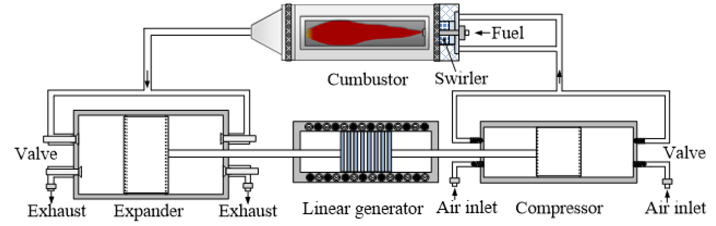
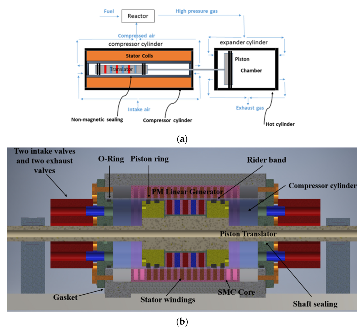
2. Linear Engine Generator Development

Figure 3 illustrates a LEG system that is comprised of an expander with a double-acting free piston mechanism, a compressor with a smaller diameter and similar mechanism, a combustor, and a generator. The only moving part of the LEG is two double-acting pistons and the translator of the generator. As the piston-translator reciprocates back and forth, air is compressed in the compressor cylinder before entering the combustor. Fuel (e.g., hydrogen and ammonia mixture) is injected into the combustor for the heat addition process. Hot exhaust gas from the combustor enters into two chambers of the expander cylinder alternatively to generate an expansion force. The expansion work deduces the work spent on the compression process to obtain the net force for electricity generation. A lab-scale prototype in terms of the illustrated LEG system was presented in detail in [14].
In the previous study’s [17] modelling and design of three alternative generators, which is composed of feasible PM arrangements, have been performed to react with the same LEG driving force in order to identify the superior generator for integration with the LEG system. Three different topologies, namely radially magnetiszed, axially magnetized, and Quasi-Halbach magnetized PM linear machines, which is shown in Figure 4, are designed, optimized, and compared within the volumetric constraints of the LEG system. Consequently, in terms of the parameter comparison results, the axially-magnetized PM linear machine (Figure 4b) offered a better performance. The design process has been reported and the results were previously validated in [18].
Two configurations of the linear machine are considered in this paper, namely the long and short translator versions with different translator masses. The lab-scale generator prototype with a long translator was carefully simulated and examined [19,20,21,22].
Figure 5a shows a long translator generator, which is the reference design with the moving mass of 9 kg (Model ‘A’) and with a slot/pole combination of 6/7. This design is also the configuration of the lab-scale prototype that has been used for experimental validation. Figure 5b shows the decreasing moving mass of the longer translator generator (reference design) to 5.2 kg (Model ‘B’); Figure 5c shows the short translator generator with fixed sheer stress and electrical machine design and the same active electromagnetic interaction as the reference design (doubled the stator length and halved the translator length) with the moving mass of 5.2 kg (Model ‘C’); and Figure 5d shows the increasing moving mass of the short translator generator to 9 kg (Model ‘D’). For the same mechanical force input profile from the linear engine, the generator with a lighter translator will have a higher velocity, hence it generates a greater back EMF and a potentially larger electrical power output. Although Model ‘A’ and ‘D’ have the same weight of the translators, a large initial electromagnetic force is generated by model ‘D’ due to the bulk amount of PMs, which makes the LEG system fail to start properly. Therefore, the comparison study focuses on the rest of the three designs. Furthermore, due to engine limitations, Model ‘A’ is unable to run on loads less than 4 Ohms.

3. A Coupled Dynamic Model of the LEG System

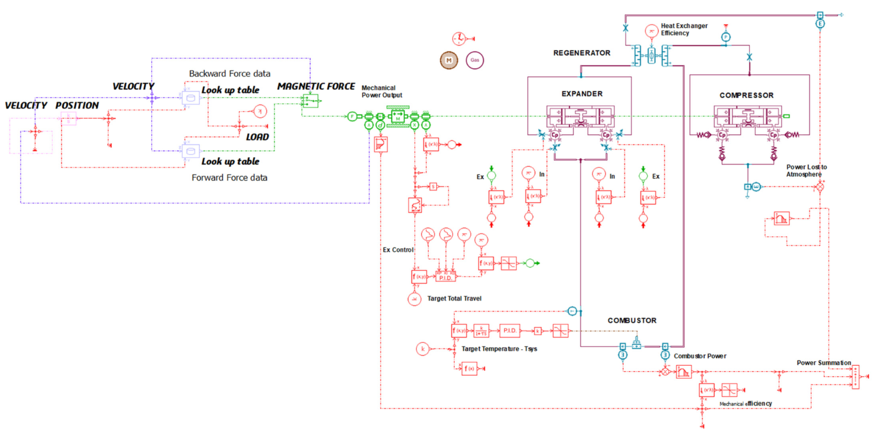
3.1. Model Structure and Simulation Implementation

To investigate the dynamic characteristics of the overall system, it is required to use an integrated model to consider the mutual effects of electrical and mechanical responses based on the work in [23,24]. A flowchart of a novel integrated model is shown in Figure 6. It is clear that there is a dynamic interaction between the engine, generator, and resistive load, and any variation in the sub models will affect the system performance. It has been shown elsewhere that, in FPEG, the translator mass should be kept to a minimum for the optimum performance of the engine [25].
The electromagnetic force behaviour of the generator while the generator is connected to the resistive load is obtained by FEA analysis, and then data are transferred to AMESim software for modelling purposes by using a series of look-up tables. In other words, data from the look-up tables are extracted from MagNet software when the generator is connected to a variety of resistive loads for a number of different velocity points. In this case, the electromagnetic force of the electrical machine is considered as a function of three inputs, namely velocity, position, and resistive load (current). Using this novel technique to model the dynamic interaction between the engine, generator, and load, it is possible to investigate the performance of the whole system in a real-time situation for further optimisation. In addition, the real generator behavior interacts with the engine rather than an ideal damper approximating a linear generator, which has been used in the literature so far. Figure 7 shows the dynamic modelling block diagram of the engine-generator.

3.2. Linear Engine Sub-Model

The linear engine dynamic model implementation with an ideal damper, which approximates the linear generator, can be found in the previous publications and the main engine geometrical parameters have been parametrized for optimal performance [14,18,23,24]. Based on Newton’s second law, the piston motion is determined by the forces acting on the moving mass, i.e., the gas force within the cylinders of the expander and compressor, the friction force, and the load force. Therefore, the piston dynamic equation can be written as Equation (1), where F g is gas force, F f is friction force, F l is load force, m is moving mass, and a is acceleration.
F g + F f + F l = m a
The gas force can be calculated from the pressure within the cylinder, which is governed by the first law of thermodynamics and expressed by Equations (2)–(5) with an ideal gas assumption, where F g is gas force, p is in-cylinder pressure, A is piston area, Q is heat input, γ is specific heat ratio, V is in-cylinder volume, m ˙ i is mass flow rate considering the inlet or outlet of the cylinder, h i is the enthalpy of the inlet or outlet flow, and the subscripts e x p and c o m represent the expander side and compressor side, respectively.
F g = F e x p + F c o m
F e x p = p e x p A e x p
F c o m = p c o m A c o m
d p d t = γ 1 V d Q d t p γ V d V d t + γ 1 V i m ˙ i h i
In order to calculate the heat transfer from the expander, compressor, and pipes to the environment, the heat transfer coefficient is obtained. The relevant equations are written below, where h is the convective heat transfer coefficient (subscripts i, o, cyl, and pipe stand for inside, outside, cylinder, and pipe, respectively), α is the overall heat transfer coefficient, A h t is the characteristic heat transfer area, T is the temperature (subscripts g, w, and 0 represent gas, wall, and environment, respectively), d is the wall thickness, k is the thermal conductivity of the wall, D is the cylinder bore diameter, Nu is the Nusselt number, and Re is the Reynolds number [26].
d Q d t = α A h t T g T 0
α = 1 1 h i + d k + 1 h o
h i , c y l = 3.26 D 0.2 p 0.8 T 0.55 w 0.8
h i , p i p e = k p i p e N u D p i p e = k p i p e D p i p e 0.0483 R e 0.783
The friction force of a free piston engine is mainly due to the piston ring and cylinder liner, and some from the bearing/shaft [16]. As non-lubricant graphite piston rings with back-bone springs were used for this study, the friction from the piston ring mainly consists of performance of the engine [27]: dry friction caused by the tension force of the piston ring ( F f d ) and the friction due to the in-cylinder pressure loading ( F f p ). The Stribeck model [28] is used to calculate F f d as expressed in Equation (11), where F f c and F f s are the Coulomb friction force and maximum static friction force, and Cs is the Stribeck constant. F f p is derived from Equation (12), where μ f p is pressure friction coefficient, p is in-cylinder pressure, D is cylinder bore diameter, and W is piston ring width.
F f = F f d + F f p
F f d = F f c + F f s F f c e 3 x ˙ C s
F f p = μ f p p π D W

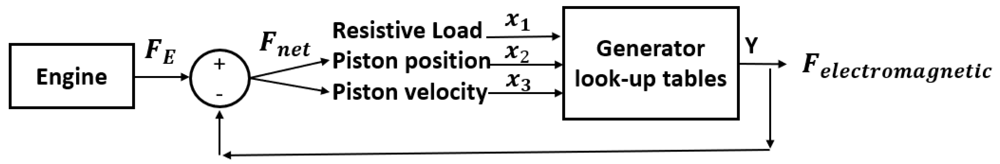
3.3. Generator Sub-Model

The force generated from the thermodynamic Joule Cycle acts as a prime mover to drive the linear generator. The piston velocity, i.e., the translator velocity, and the total force from the working gas in the cylinders are fed into the linear generator. These two input variables to the linear generator are affected by responding forces from the linear generator, which in turn influence the dynamic balance of the linear motion of the joule engine. The linear generator responding forces F l a can be divided into its components (Equation (13), [29]).
F l a = F e l e + F c o g + F c o + F e d + F c p + F a r
where F e l e : electrical force,   F c o g : cogging force,   F c o : core loss force,   F e d : eddy current force, F c p : copper loss force, and F a r : armature reaction force. For simplicity and accurate results, the linear generator responding forces ( F l a ) are obtained by the help of the Finite Element Analysis (FEA) modelling method, and then look-up tables are created and used to model the aggregated linear generator responding forces.

3.4. Input Parameters of the Coupled Model

The parameters of the three models are shown in Table 1.

4. Model Validation and Performance Prediction

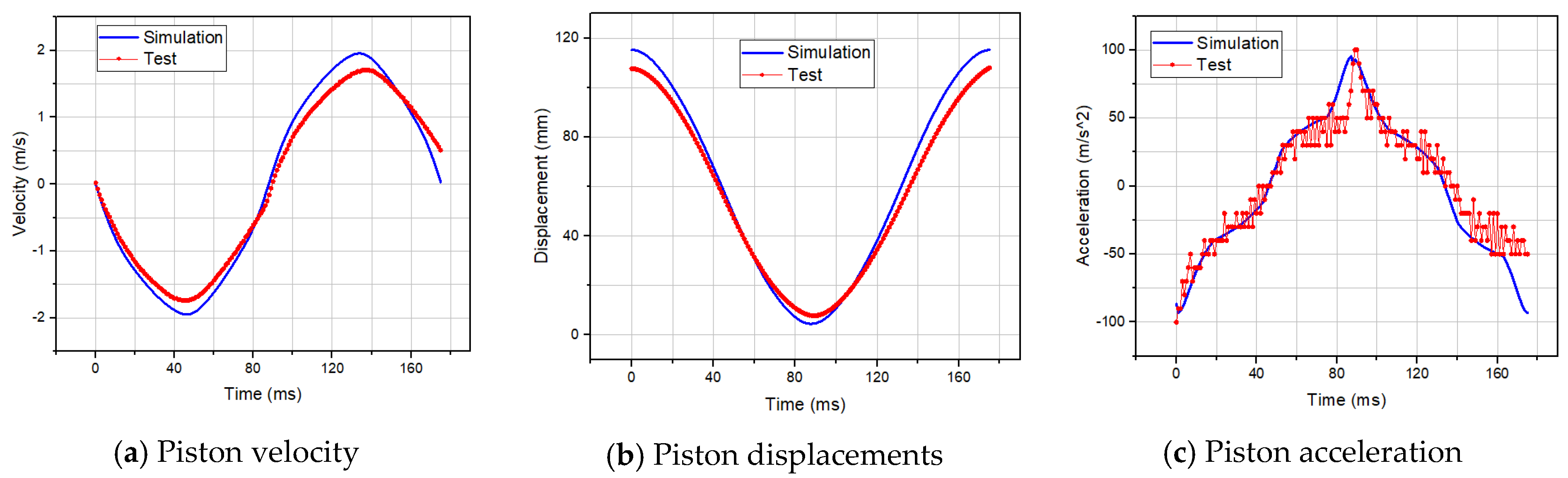
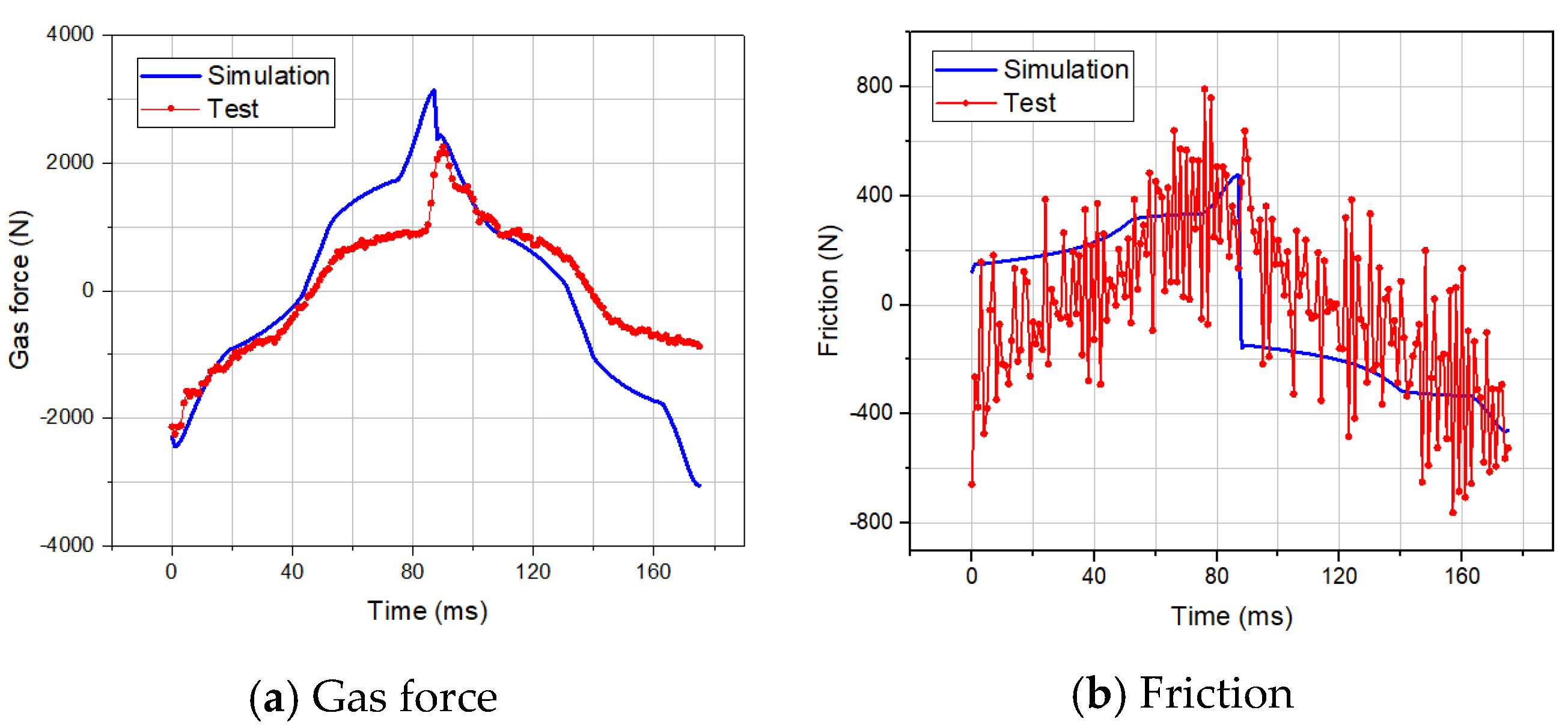
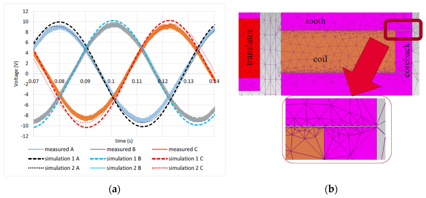
4.1. Linear Engine Sub-Model Validation

It is necessary to verify the prototype dynamic model before extensive parameter analysis. The verification is based on the experiment results, and the detail of the prototype has been previously presented [14,23]. In the prototype engine, a moving mass load is used to replace a linear generator, and compressed air from outside is used to start the engine. When the expander piston reaches its Top Dead Centre (TDC), the expander inlet valve opens, and then the piston is pushed to its Bottom Dead Centre (BDC) by the high-temperature and high-pressure working fluid to complete an expansion stroke. At the same time, the compressor piston connected by the shaft with the expander piston moves synchronously and completes a compression stroke. The exhaust valve of the expander begins to open at the start of the expansion stroke and closes near the TDC position, which is controlled by the engine control unit and the compressor valves open and close according to the set value of the pressure in the compressor. Comparisons of the piston movement characteristics of the test and simulation results are presented in Figure 8.
Figure 9 describes the gas force and friction force comparisons, respectively. The comparison of gas forces shows that the test and simulation results have the same trend and a relatively small gap. The gas force is measured indirectly, which is based on the dynamic balance of the moving mass. When the piston reaches TDC and BDC, the maximum gas forces of the test and simulation reach 2255.42 N and 3140.20 N, respectively, which could be explained by the high pressure in the chambers. The errors of the gas forces and friction forces will cancel each other and not be passed onto the electric side. The difference between the test and simulation results may be due to the possibility of leakage near the TDC in the experiment. More consideration for the effects of leakage in the simulation model may further improve the model. In addition, it shows that the simulation results and the test result of the friction force are not as consistent as the previous parameters. The simulation friction result shows the friction increases from 120N to 476 N with the piston movement and changes direction when the piston turns. The test friction has a larger fluctuation but has a rough consistency with the simulation friction. Hence, the dynamic behaviour of the prototype engine has been understood.

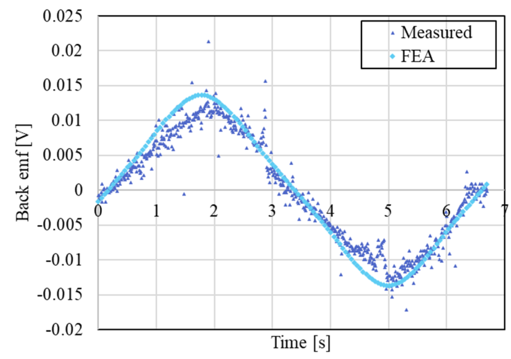
4.2. PM LSM Sub-Model Validation

In this test, the prototype was directly driven by a ball screw (i.e., actuator) with a maximum velocity of 5.7 mm/s. No-load back EMF waveforms obtained from the simulation and experimental results for one phase are plotted on the same graph, as shown in Figure 10. Soft magnetic composite (SMC)-based stator components might change their magnetic properties whilst they are machined in real life. This might be one of the reasons that the measured and simulated results in Figure 10 do not match perfectly.
The peak value of the predicted no-load beck EMF is 14 mV, where a deviation rounding can be approximately (≈9.5%) seen, however, this may be considered fair with the existing noise in the measured signal at this very low speed. In addition, the characteristics of the material used in the FEA model may not match the characteristics of the real material used in the prototype. Design tolerance in the manufacturing process also plays a significant role, which may result in inaccurate dimensions.

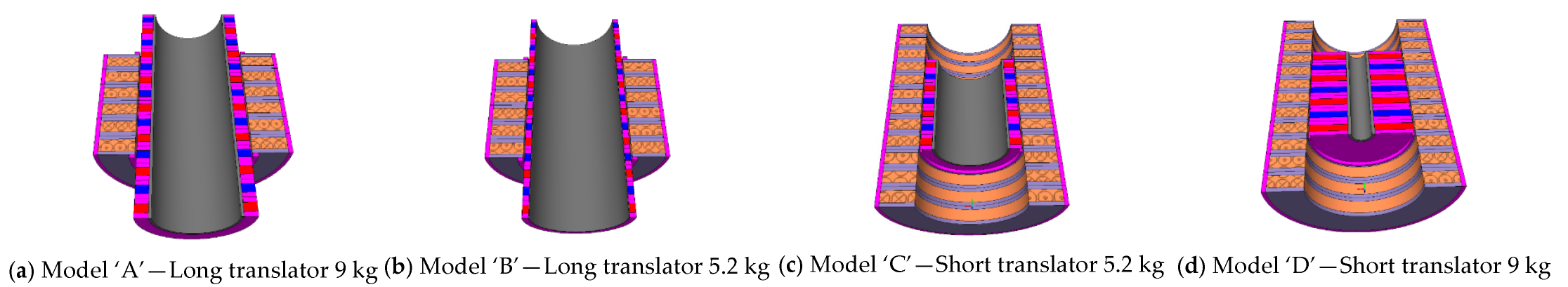
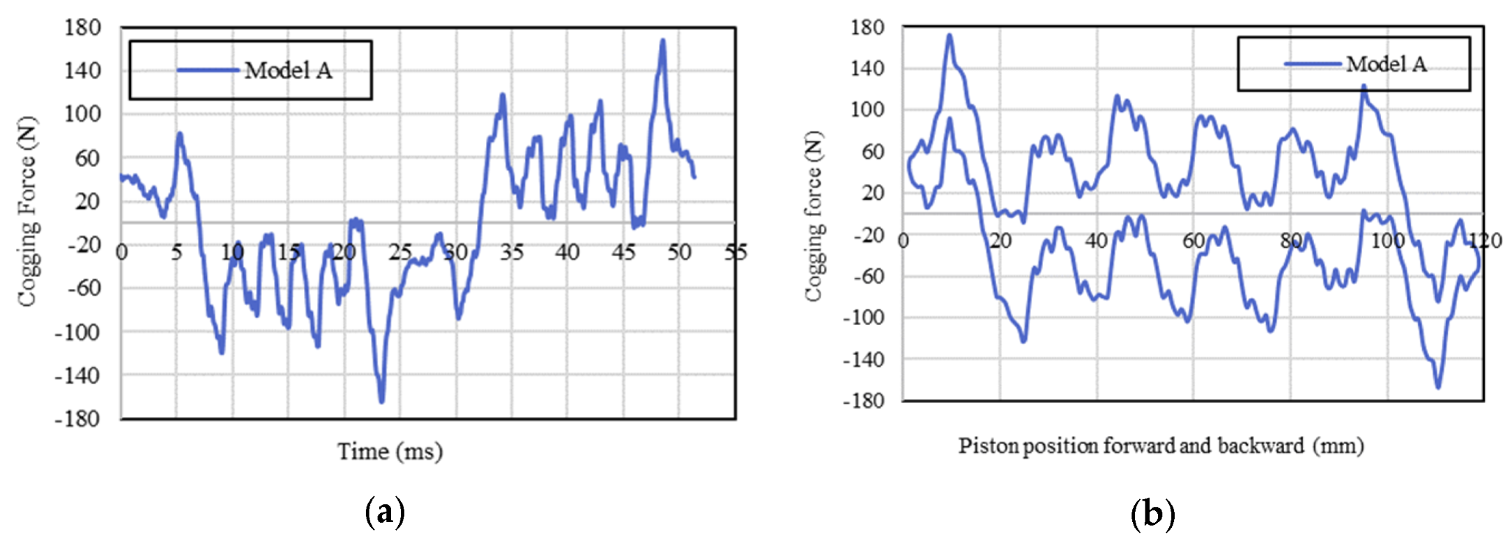
4.3. Performance Prediction of the LEG System with Long Translator Generator (Model ‘A’)

The electric power generated from the Model ‘A’ generator is depicted in Figure 11. The associated mechanical power generation versus the load resistance is also shown. The Model ‘A’ generator is capable of generating about 1.8 kW of electric power from 2 kW of mechanical power input that is generated in the thermodynamic process. The generator efficiency and the LEG system efficiency are also given in Figure 11.
Using the dynamic model, the variation of the phase voltages, phase currents, and power dumped in the load resistance, at peak load condition of 5 Ohms, are shown in Figure 12a–c. It shows the amplitude imbalance over the entire mechanical cycle with variable electrical frequency (fe = 130 Hz) operations.
An ideal damper that mimics the linear generator omits the effects of the detailed electromagnetic force, machine losses, and magnetic force ripples, which presents a very smooth overall electromagnetic force versus the piston displacement and time, which is illustrated in Figure 13. These results enable the system designers to investigate the effect of the actual generator reacting force on the linear engine performance, rather than assuming the electrical machine behaves simply as a damper, where the reacting force varies linearly with velocity acting against the engine’s driving force. The effects of the machine inductance, saturation, tooth/slots, and finite length of the stator/translator cause disturbances. The resultant actual reacting force with fluctuations will have an impact on the thermodynamic performance of the engine.
With the coupled model of the LEG, the linear engine is connected to the generator, which is in an open circuit condition to look at the ripple force of the generator. This ripple force, i.e., the cogging force, is due to the non-uniformity of the reluctance path in the air gap area (slot effects) and oversizing of the translator or stator (end effects), as well as the velocity effect/core loss (iron loss and eddy current loss). The cogging force of the Model ‘A’ generator versus time and piston position can be seen in Figure 14.

5. Results and Discussion

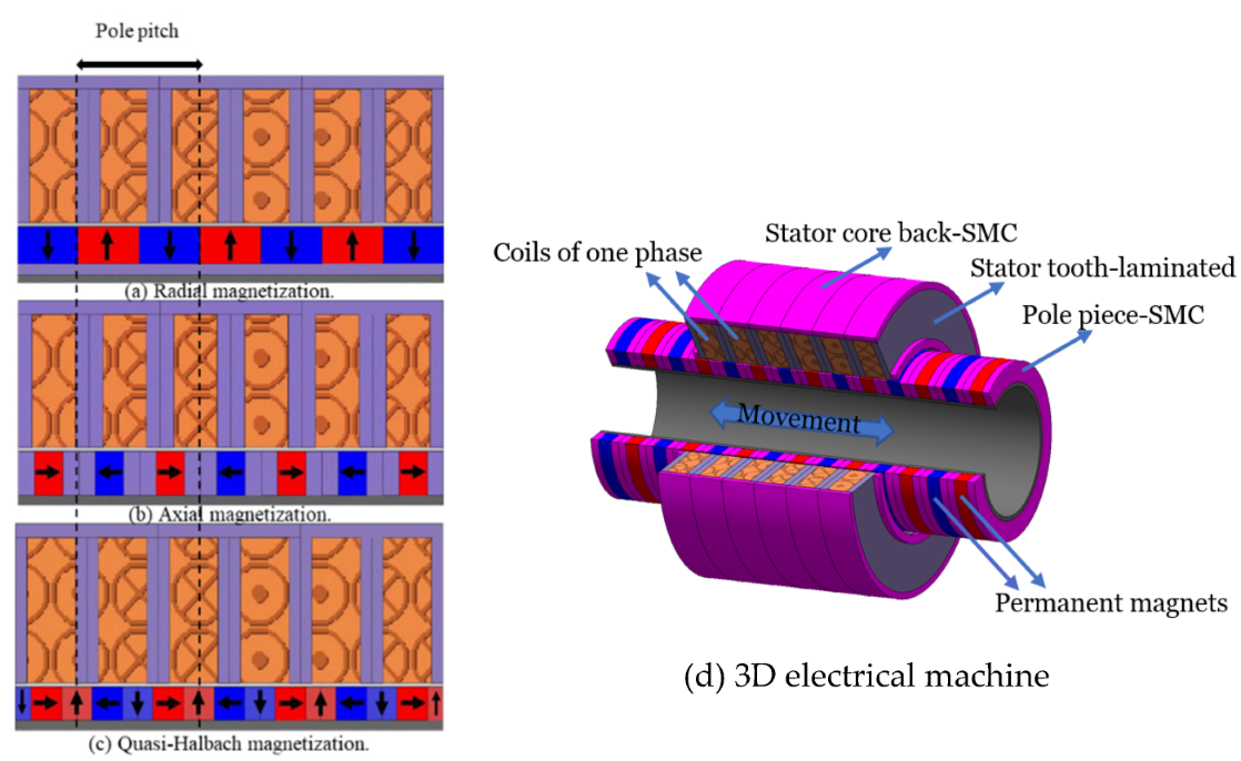
5.1. Alternative Topologies of PM Generator-MagNet FEA Analysis

Electric power versus resistive load, which is characteristic of two configurations of short and long translator generators, can be seen in Figure 15. In the FEA software, the applied velocity to the translator was kept constant for both configurations regardless of the mass of the translator, and it is equal to 5 m/s. Figure 15 illustrates that model ‘A’ generates approximately 3.8 kW of electric power, which is double the amount of electric power generation compared to model ‘C’. The reason behind this is that in the model ‘A’ generator, all coils are active at any time instant, contributing to generate output power, whereas in the model ‘C’ generator half the number of coils are inactive at any time instant and act as an external consumer of load, reducing electrical power generation. In the model ‘B’ generator, since the number of PMs is halved compared to the PMs in the model ‘A’ generator and the electrical power is also approximately halved.

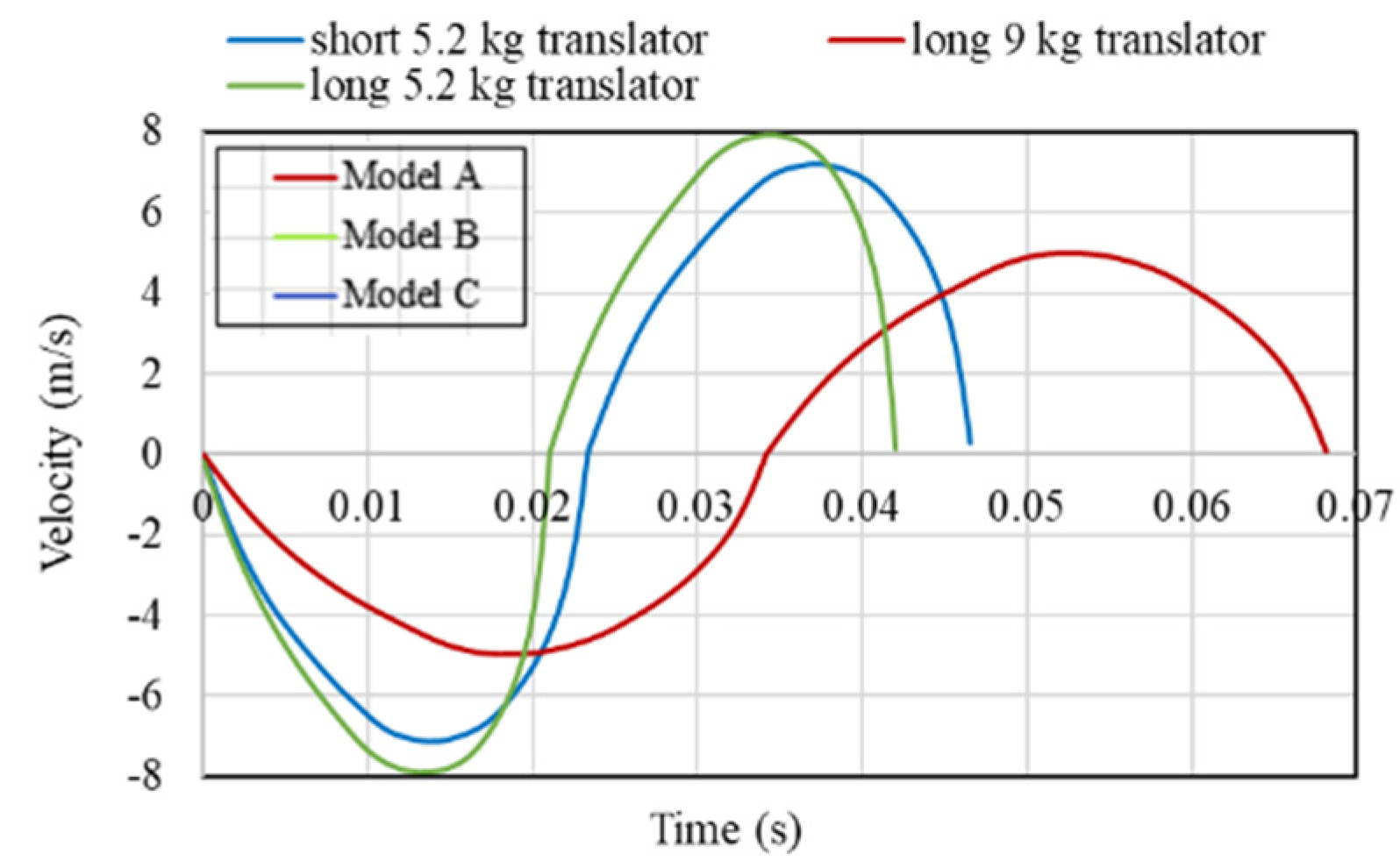
5.2. The Linear Engine Spontaneous Response to Alternative Topologies of PM Generator

Figure 16 represents the comparison of the velocity of three models versus piston displacement. Model ‘A’ has the lowest peak velocity of 4.9 m/s for the heaviest piston mass. Model ‘C’ has a peak velocity of 7.1 m/s and model ‘B’ has the highest value of 7.9 m/s. This could reflect the reality that model ‘B’ has the highest frequency while three models have a nearly equal stroke. However, the position of the peak velocity is not in the center of the stroke and the velocity versus displacement curve is not a standard ellipse, which is related to the reality that the balanced position of the piston is not in the center due to load force, friction, and valve timing. In more detail, due to the valve control mechanism, the gas force is relatively large at the beginning of the stroke and gradually decreases to the value of the sum of other forces in different directions. This is the force balance point where the piston exceeds the stroke center, and the velocity reaches a peak value.
The air is compressed in the compressor part and the pressure increases with the decrease of the volume of the compressor, which can be seen in Figure 17. Model ‘B’ has the highest pressure (9.78 bar) when the volume reduces to the position near TDC and BDC, while model ‘A’ has the lowest peak pressure (7.49 bar). The pressure amplitude in Model ‘B’ is the largest among the models. The three cases (i.e., Model ‘A’–‘C’) apply roughly the same valve timings, therefore the velocity profiles, and, in turn, the frequencies of the systems, play a key role in pressure build-up. With the heaviest moving mass, Model ‘A’ develops the lowest peak pressure in the compressor and the lowest frequency of the system, which leads to the lowest peak pressure after the pressure balance is established. For Model ‘B’ and ‘C’, which have the same weight for their moving masses, the slight difference of stroke length causes the difference in peak pressure. With less resistance than Model ‘B’, it has the longest stroke compared to the target stroke of 120 mm, which results in its top peak pressure in the thermodynamic cycles. In Figure 18, the peak pressure discrepancy is also derived from the abovementioned reasons.
Figure 18 describes the pressure changes in the expander with the changes of the expander volume. In the expander part, the high-temperature and high-pressure air is input in the expander from point ‘a’ to point ‘b’ to push the expander piston. Model ‘B’ has the highest pressure of 9.78 bar, while Model ‘A’ and Model ‘C’ are 7.49 bar and 8.73 bar, respectively.

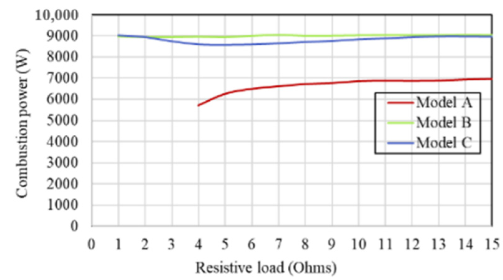
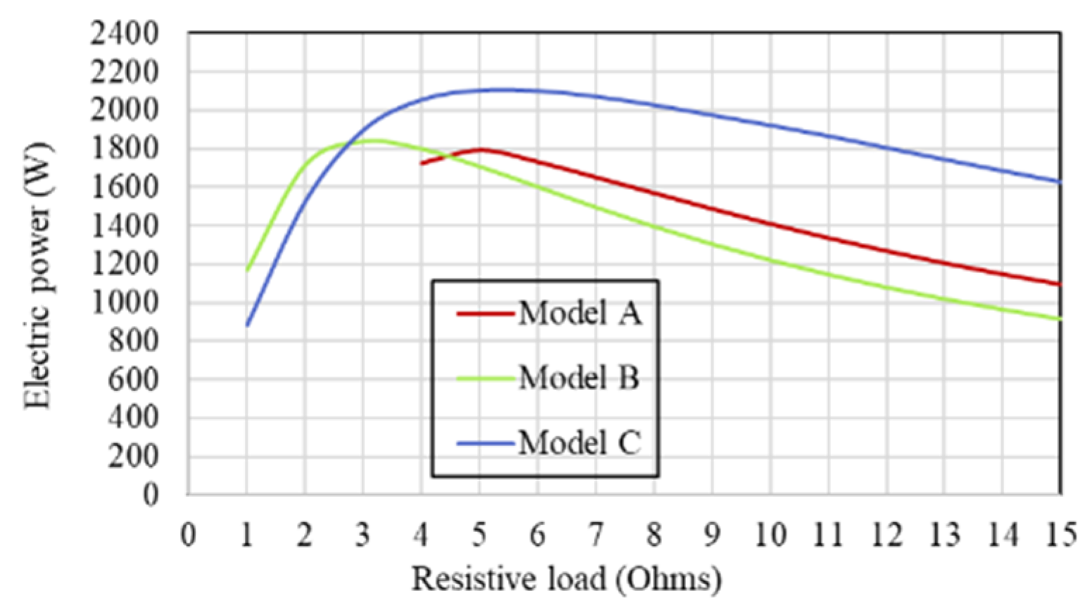
5.3. The LEG Performance Comparison

5.3.1. Energy Inputs and Outputs

The variation in the combustion heat input due to applying different external resistive loads to the generator have been studied, which is shown in Figure 19. It is revealed that the combustion heat input is progressively increased with the load resistance increase for Model ‘A’, whereas for the other two generator models they are constant. Peak combustion heat inputs versus resistive loads in the Model ‘B’ and ‘C’ generator models are generally greater than the Model ‘A‘ design. This indicates that combustion heat input is directly linked with moving mass. At a load of 4 Ohms connected to the terminals of generator Model ‘B’ and ‘C’, the generators require about 34% more combustion heat input compared to Model ‘A’. In Figure 20, it is shown that the Model ‘C’ generator can generate about 15% more electric power compared to other generators.
Figure 21 illustrates the velocity profiles of the piston/translator assembly in a single cycle (two strokes). The lighter moving mass demonstrates a shorter cycle time and higher frequency compared to the heavier moving mass. Due to the reduced frequency of the intake valves, the overall combustion heat input of the LEG system with the heavier moving mass decreases.

5.3.2. Energy Density Comparison

Table 2 reveals a comprehensive comparison of alternative generators. Model ‘C’ can produce 2120 Watts output power, which is about 16.5% and 19% more than model ‘A’ and ‘B’, respectively. However, the Model ‘A’ generator can achieve the highest system efficiency of 30% among other generators. In terms of the ratio of power versus cost and power versus volume, Model ‘C’ is superior, however Model ‘A’ is better for the power versus weight of the electrical machine.

6. Discussion on System Integration

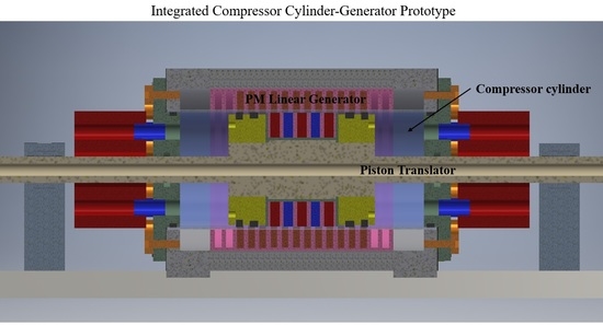
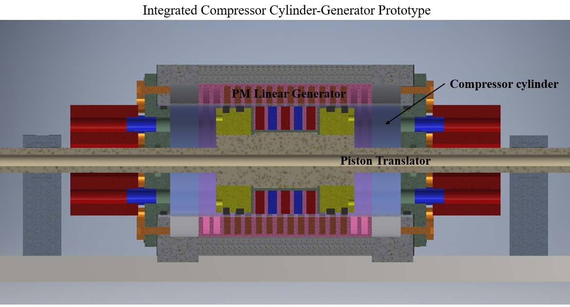
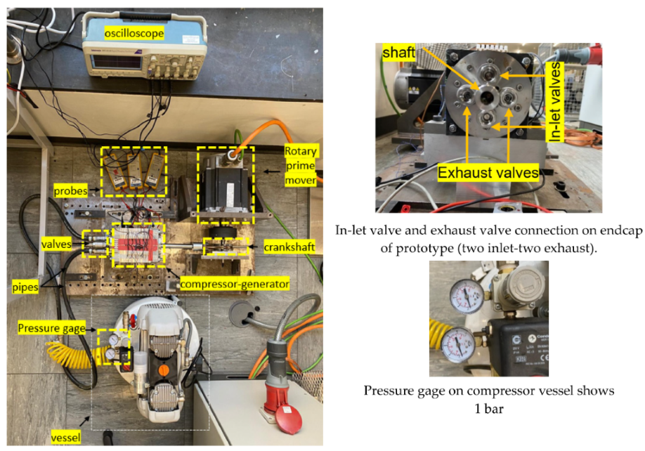
6.1. Proposed Integrated Prototype

Figure 22 shows how the electrical machine is intended to fit within the FPEG air compressor. The short translator generator saves space and has the potential for an integrated design, high efficiency, compact size, and flexibility in renewable energy integration.
The fundamental issue of integrating an electrical machine with a compressor cylinder is ensuring that the fluid does not skip from chambers for the piston/translator to compress the air or working fluid into a high compression ratio. When the temperature in the compressor cylinder rises, materials with a high working temperature point must be employed. Furthermore, incorporating valves on end plates and shaft sealing are the remaining issues that were thoroughly explored and addressed in [30,31].

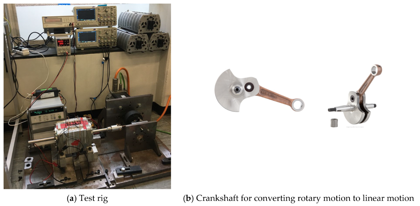
6.2. Prototype Testing

Figure 23 depicts the laboratory assembly setup, in which the linear prototype machine (i.e., compressor cylinder-generator) is attached to a crankshaft mechanism, prime mover, and drive unit to simulate the operation of the combustor and expander cylinder. It was not possible to build and integrate this generator-compressor cylinder prototype with an engine’s expanding cylinder, hence the translator/piston assembly must be connected to a linear motion prime mover to mimic the expander cylinder performance. A crankshaft is used in the conversion of rotary to linear motion. It is one of the hardest-working components and converts the prime mover’s rotary movement into linear motion. The specifics are as follows: Direct intake, bell-shaped, Stroke is 50.0 mm, Conrod is 110.0 mm, Pin is 15 mm, and Conrod pin is 21 mm.

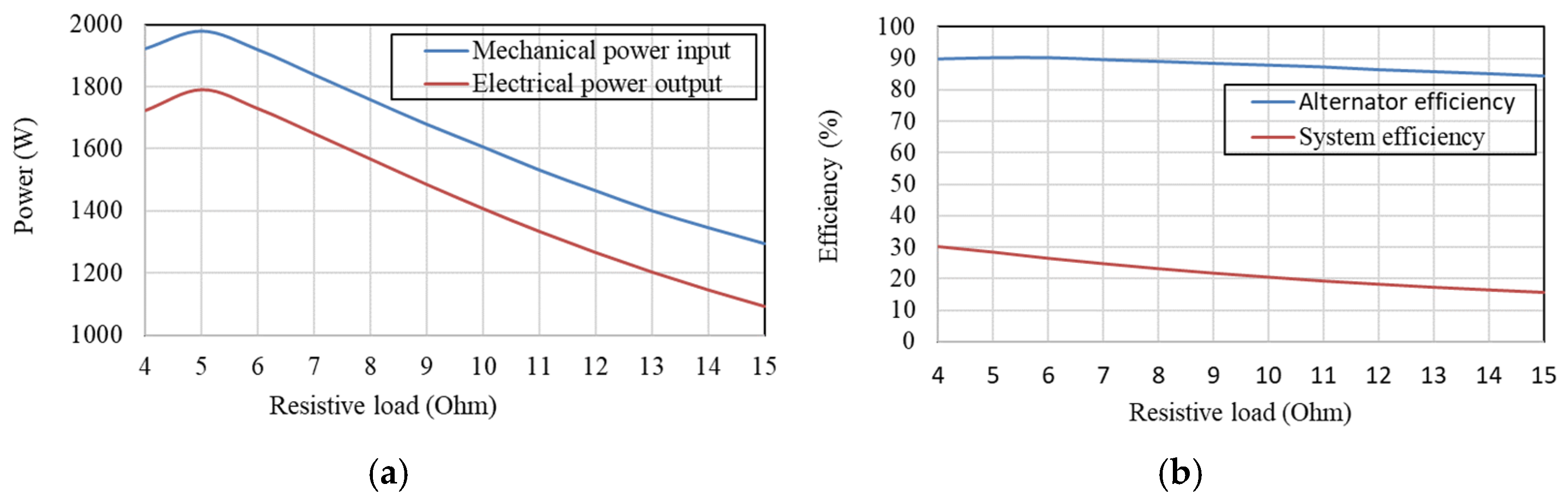
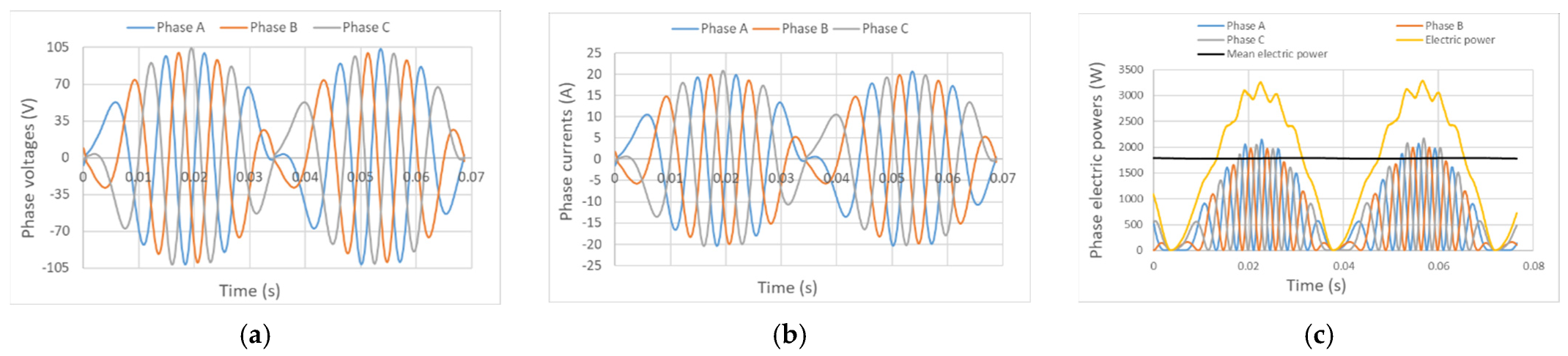
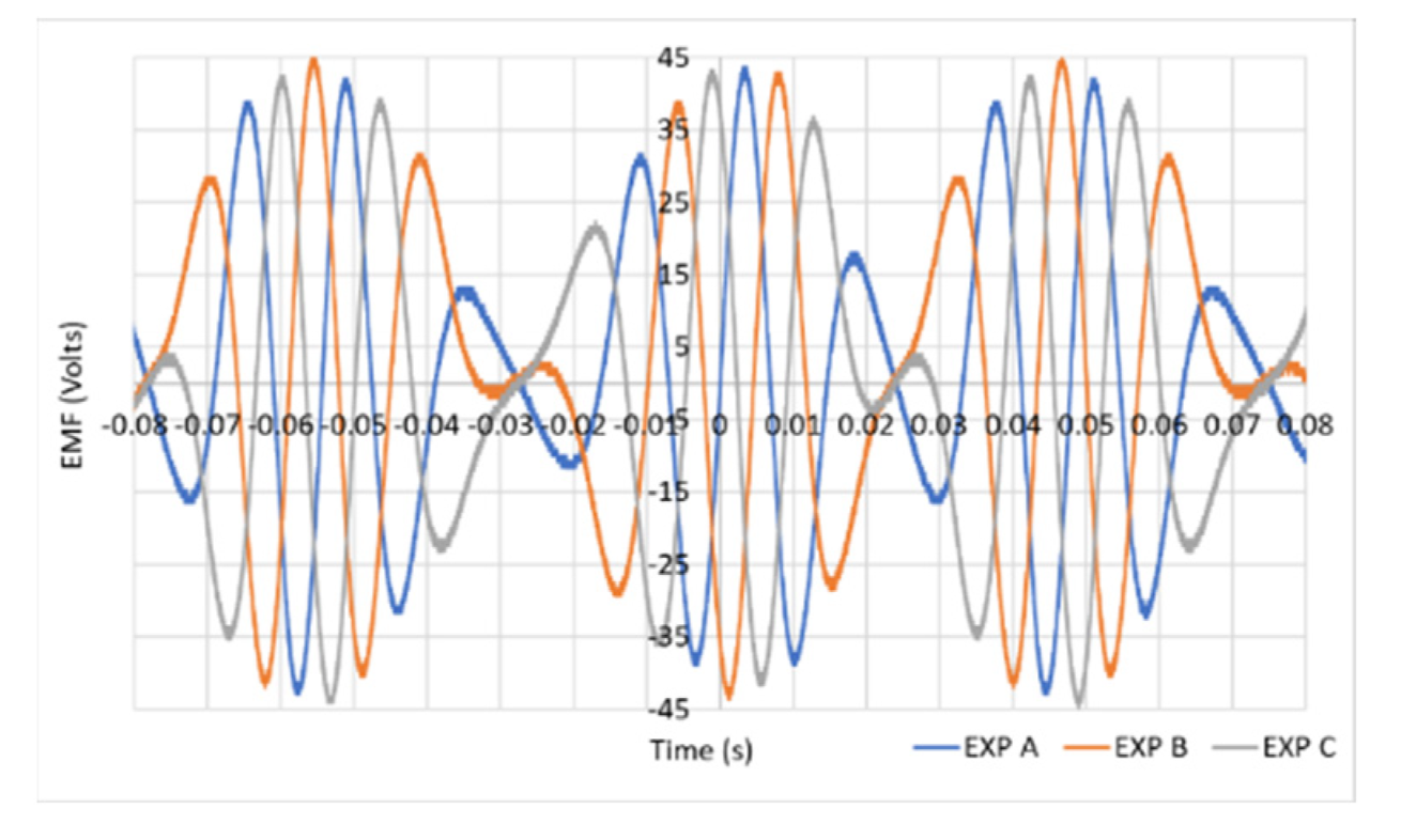
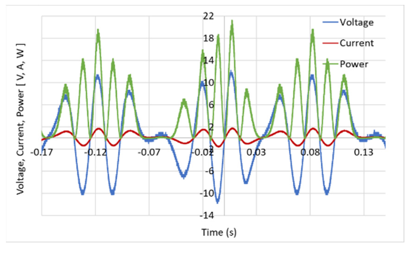
6.2.1. No-Load Electrical Testing

The results of an open circuit test with a continuous rotational speed of 600 rpm and a peak speed of 1 m/s are shown in Figure 24. Since both sides of the compressor cylinder were vented to the atmosphere, this was strictly an electrical test rather than an electro-mechanical test. Since the three phases of the machine are well balanced, there is confidence in the assembly of the SMC stator components and the concentricity of the bearings. Table 3 gives the key results of the open circuit test. A comparison between the predicted and simulated back EMF at a fixed speed of 0.3 m/s is shown in Figure 24. The model is seen to overpredict by around 10% compared to an idealized finite element analysis simulation; reasons for this will include damage to the SMC material and possible parasitic air gaps in the stator assembly. To investigate just one of these effects, a small air gap was inserted between the SMC teeth and coil carrying coreback components in the finite element analysis model, as shown in Figure 25. The results of the back EMF prediction for a gap of 0.05 mm were also shown in Figure 25 and bring the agreement between the measured and simulated results closer.
The difference between the simulation and experimental results in Figure 25a could be due to several reasons: uneven machine air gap length in real life, manufacturing of the translator affected by the components’ tolerance, and the electromagnetic performance of the SMC components machined before assembly.

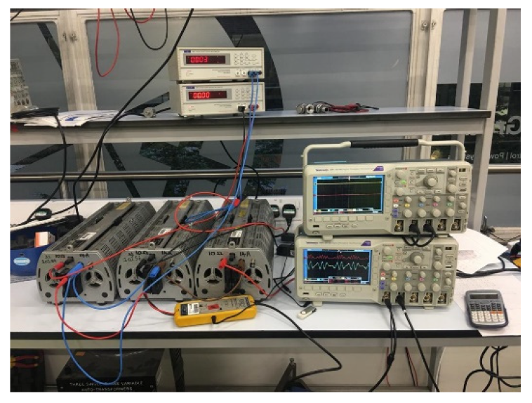
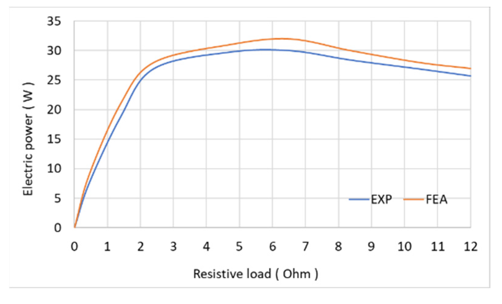
6.2.2. On-Load Electrical Testing

To electrically load the generator, the three phases were connected to a star-connected three-phase resistive load, as shown in Figure 26, and the voltage, current, and electric power of one phase when operating at 300 rpm and a peak speed of 0.5 m/s were recorded (Figure 27). Figure 28 compares the measured and simulated power output for a variation in load resistance. It is found that for both measured and FEA, the maximum power of 30 W occurred at 6 Ω. The simulated power using the model excluding the parasitic air gaps (Simulation-1) overpredicts the output power by almost 10%.

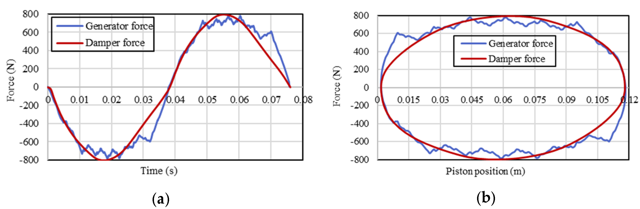
6.2.3. Compression Test

In order to test the compressor cylinder’s pressure capability, the inlet and exhaust valves were installed in the endcap, and two exhaust valves were piped to a pressure vessel, as shown in Figure 29. The air was stored in an accumulator, and the pressure was seen increasing with each compression stroke. For safety considerations, the test was stopped after a few cycles once the pressure hit 1 bar. Thus, the concept of a combined generator/compressor cylinder was successfully proven in the prototype.

7. Conclusions

Experimental tests on a novel integrated compressor cylinder-generator system prototype were successfully completed in this study, demonstrating that the concept is feasible and that the prototype can generate electrical power and compressed air simultaneously. As a result, this paper claims that a linear generator can be integrated into a compressor cylinder while overcoming mechanical challenges.
The dynamic and thermodynamic characteristics of a LJEG system with an alternative generator configuration are presented in detail. By decreasing the moving mass of the system, more power can be generated in a short translator generator (i.e., Model ‘C’) at the expense of consuming more fuel or combustion power compared to long translator generators. Short translator generators generate more electric power with lower efficiency and higher combustion power compared to a long translator generator (i.e., Model ‘A’ and ’B’), which generates a little less power with higher efficiency at lower combustion power.
A short translator generator has a higher frequency compared to a long translator generator, implying that if the frequency is high, the valves will open and close more frequently and more hot air is drawn from the combustor. This results in the requirement of more combustion power to warm up the air in the combustor before moving to the engine for expansion-compression purposes. Therefore, Model ‘C’ is more promising in terms of electric power generation.
It might be concluded that during the launching of the FPEG system, the short translator (i.e., Model ‘C’) can consume less fuel because of its lighter mass compared to a long translator generator (i.e., Model ‘A’ and ‘B’). In other words, in the transient condition of the system, the short translator consumes less combustion power to drive/push the piston-translator, however in the steady state condition, the short translator generator (i.e., Model ‘C’), due to having a lighter mass and higher frequency, consumes more fuel or combustion power. In the start mode of the system, the short translator perhaps consumes less energy compared to the long one because, initially, the engine is required to push the translator to reach a certain frequency, so the one with a heavier mass would consume more fuel.
Depending on the requirements of the application, a short or long translator generator can be adapted. A short translator is preferable since it occupies less volume and is good for compact systems, however, if the weight is important, a long translator can be chosen. In terms of cost, a short translator is more economical because of the use of overhanging stators with 50% less permanent magnet material. Furthermore, an FPEG system with a short translator generator (i.e., Model ‘C’) is preferable in terms of system cost and volume, whereas Model ‘A’ is a better option in terms of system efficiency in comparison to Model ‘B’ and ‘C’.

Author Contributions

Conceptualization: R.M.K. and D.W.; Software Validation: R.M.K. and M.L.; Investigation: R.M.K., N.J.B. and D.W.; Resources: N.J.B.; Data Curation: R.M.K., D.W., A.S.J. and M.L.; Project Administration: N.J.B., D.W. and M.C.K.; Writinng—review and editing: R.M.K. and M.C.K.; Funding Acquisition: D.W. and N.J.B. All authors have read and agreed to the published version of the manuscript.

Funding

This work was funded by EPSRC (Engineering and Physical Sciences Research Council) Impact Acceleration Account with funding reference number: EP/N509528/1.

Institutional Review Board Statement

Not applicable.

Informed Consent Statement

Not applicable.

Conflicts of Interest

The authors declare no conflict of interest.

Abbreviations

LEGLinear Engine Generator
FPEGFree Piston Engine Generator
LJEGLinear Joule Engine Generator
PMPermanent Magnet
TDCTop Dead Centre
BDCBottom Dead Centre
SMCSoft Magnetic Composite

References

  1. Hansson, J. Analysis and Control of a Hybrid Vehicle Powered by Free-Piston Energy Converter. Ph.D. Thesis, KTH Royal Institute of Technology, Stockholm, Sweden, 2006. [Google Scholar]
  2. Hansson, J.; Leksell, M. Performance of a Series Hybrid Electric Vehicle with a Free-Piston Energy Converter. In Proceedings of the 2006 IEEE Vehicle Power and Propulsion Conference, Windsor, UK, 6–8 September 2006; IEEE: Piscataway, NJ, USA, 2006; pp. 1–6. [Google Scholar] [CrossRef]
  3. Goldsborough, S.S.; Van Blarigan, P. A Numerical Study of a Free Piston IC Engine Operating on Homogeneous Charge Compression Ignition Combustion. SAE Trans. 1999, 108, 959–972. [Google Scholar]
  4. Goldsborough, S.S.; Van Blarigan, P. Optimizing the Scavenging System for a Two-Stroke Cycle, Free Piston Engine for High Efficiency and Low Emissions: A Computational Approach. SAE Trans. 2003, 112, 1–20. [Google Scholar]
  5. Van Blarigan, P.; Paradiso, N.; Goldsborough, S. Homogeneous Charge Compression Ignition with a Free Piston: A New Approach to Ideal Otto Cycle Performance; SAE International: Warrendale, PA, USA, 1998. [Google Scholar]
  6. Atkinson, C.M.; Petreanu, S.; Clark, N.N.; Atkinson, R.J.; McDaniel, T.I.; Nandkumar, S.; Famouri, P. Numerical Simulation of a Two-Stroke Linear Engine-Alternator Combination. SAE Trans. 1999, 108, 1416–1430. [Google Scholar]
  7. Famouri, P.; Cawthorne, W.R.; Clark, N.; Atkinson, R.J.; McDaniel, T.I.; Nandkumar, S.; Famouri, P. Design and testing of a novel linear alternator and engine system for remote electrical power generation. In Proceedings of the IEEE Power Engineering Society, 1999 Winter Meeting (Cat. No.99CH36233), New York, NY, USA, 31 January 1999–4 February 1999; IEEE: Piscataway, NJ, USA, 1999. [Google Scholar]
  8. Mikalsen, R.; Roskilly, A.P. Performance simulation of a spark ignited free-piston engine generator. Appl. Therm. Eng. 2008, 28, 1726–1733. [Google Scholar] [CrossRef]
  9. Ferrari, C.; Friedrich, H.E. Development of a free-piston linear generator for use in an extended-range electric vehicle. In Proceedings of the EVS26 2012, Los Angeles, CA, USA, 6–9 May 2012. [Google Scholar]
  10. Kosaka, H.; Akita, T.; Moriya, K. Development of free piston engine linear generator system part 1—Investigation of fundamental characteristics. In SAE 2014 World Congress & Exhibition; SAE International: Warrendale, PA, USA, 2014. [Google Scholar]
  11. Goto, S.; Moriya, K.; Kosaka, H.; Akita, T.; Hotta, Y.; Umeno, T.; Nakakita, K. Development of free piston engine linear generator system part 2—Investigation of control system for generator. In SAE 2014 World Congress & Exhibition; SAE International: Warrendale, PA, USA, 2014. [Google Scholar]
  12. Ngwaka, U.; Smallbone, A.; Jia, B.; Lawrence, C.; Towell, B.; Roy, S.; Shivaprasad, K.V.; Roskilly, A.P. Evaluation of performance characteristics of a novel hydrogen-fuelled free-piston engine generator. Int. J. Hydrog. Energy 2021, 46, 33314–33324. [Google Scholar] [CrossRef]
  13. Mikalsen, R.; Roskilly, A.P. The free-piston reciprocating Joule Cycle engine: A new approach to efficient domestic CHP generation. In Proceedings of the ICAE 2012 Conference, Suzhou, China, 5–8 July 2012. [Google Scholar]
  14. Wu, D.; Roskilly, A.P. Design and parametric analysis of linear Joule-cycle engine with out-of-cylinder combustion. Energy Procedia 2014, 61, 1111–1114. [Google Scholar] [CrossRef] [Green Version]
  15. Jia, B.R.; Wu, D.; Andrew, S. Dynamic and thermodynamic characteristics of a linear Joule engine generator with different operating conditions. Energy Convers. Manag. 2018, 173, 375–382. [Google Scholar] [CrossRef]
  16. Ngwaka, U.; Jia, B.; Lawrence, C.; Wu, D.; Smallbone, A.; Roskilly, A.P. The characteristics of a Linear Joule Engine Generator operating on a dry friction principle. Appl. Energy 2019, 237, 49–59. [Google Scholar] [CrossRef]
  17. Jalal, A.S.; Baker, N.J.; Wu, D. Design of tubular Moving Magnet Linear Alternator for use with an External Combustion—Free Piston Engine. In Proceedings of the 8th IET International Conference on Power Electronics, Machines and Drives (PEMD 2016), Glasgow, UK, 19–21 April 2016; pp. 1–6. [Google Scholar] [CrossRef] [Green Version]
  18. Jalal, A.S. Design and Performance Investigation of Flux—Concentrated Tubular Linear Generator for an External Combustion Free Piston Engine. Ph.D. Thesis, Newcastle University, Newcastle, UK, 2017. [Google Scholar]
  19. Baker, N.J.; Korbekandi, R.M.; Jalal, A.S.; Wu, D. Performance of a tubular machine driven by an external-combustion free-piston engine. J. Eng. 2019, 2019, 3867–3871. [Google Scholar] [CrossRef]
  20. Baker, N.J.; Jalal, A.S.; Wang, J.; Korbekandi, R.M. Experimental comparison of two linear machines developed for the free piston engine. J. Eng. 2019, 2019, 4406–4410. [Google Scholar] [CrossRef]
  21. Korbekandi, R.M.; Baker, N.J.; Wu, D. A study of translator length in a tubular linear electrical machine designed for use in a linear combustion joule engine. In Proceedings of the 12th International Symposium on Linear Drives for Industry Applications (LDIA), Neuchâtel, Switzerland, 1–3 July 2019; pp. 1–6. [Google Scholar] [CrossRef]
  22. Baker, N.J.; Korbekandi, R.M.; Wu, D.; Jalal, A.S. An Investigation of Short Translator Linear Machines for Use in a Free Piston Engine. In Proceedings of the IEEE International Electric Machines & Drives Conference (IEMDC), Virtual Event, 12–15 May 2019; pp. 68–73. [Google Scholar] [CrossRef]
  23. Wu, D.; Tan, H.M.; Jia, B.; Roskilly, A.P. A preliminary experimental study on a lab-scale Linear Joule Engine prototype. Energy Procedia 2019, 158, 2244–2249. [Google Scholar] [CrossRef]
  24. Jia, B.; Wu, D.; Smallbone, A.; Lawrence, C.; Roskilly, A.P. Design, modelling and validation of a linear Joule Engine generator designed for renewable energy sources. Energy Convers. Manag. 2018, 165, 25–34. [Google Scholar] [CrossRef] [Green Version]
  25. Mikalsen, R.; Roskilly, A.P. A review of free-piston engine history and applications. Appl. Therm. Eng. 2007, 27, 2339–2352. [Google Scholar] [CrossRef] [Green Version]
  26. Bade, M.; Clark, N.N.; Musho, T.; Famouri, P. Piston Rings Friction Comparison in a Free Piston and Conventional Crankshaft Engines. In Proceedings of the ASME 2018 Internal Combustion Engine Division Fall Technical Conference, San Diego, CA, USA, 4–7 November 2018; Volume 2. [Google Scholar]
  27. Heywood, J.B. Internal Combustion Engine Fundamentals; Mcgraw-Hill: New York, NY, USA, 1988; Volume 930. [Google Scholar]
  28. Pennestrì, E.; Rossi, V.; Salvini, P.; Valentini, P.P. Review and comparison of dry friction force models. Nonlinear Dyn. 2016, 83, 1785–1801. [Google Scholar] [CrossRef]
  29. Jalal, A.S.; Baker, N.J.; Wu, D. Electrical machine design for use in an external combustion free piston engine. In Proceedings of the 5th IET International Conference on Renewable Power Generation (RPG) 2016, London, UK, 21–23 September 2016; pp. 1–6. [Google Scholar] [CrossRef] [Green Version]
  30. Korbekandi, R.M.; Baker, N.J. Design, build and testing of an integrated compressor-generator. In Proceedings of the 2021 IEEE Energy Conversion Congress and Exposition, Vancouver, BC, Canada, 10–14 October 2021; IEEE: Piscataway, NJ, USA, 2021. [Google Scholar]
  31. Korbekandi, R.M.; Baker, N.J.; Kulan, M.; Wu, D. Modelling and build of an integrated linear engine generator designed for power density. In Proceedings of the IEEE Energy Conversion Congress and Exposition, Vancouver, BC, Canada, 10–14 October 2021; IEEE: Piscataway, NJ, USA, 2021; pp. 4103–4110. [Google Scholar] [CrossRef]
Figure 1. Efficiency from fuel to electrical power to the DC-link for an FPEG and a typical diesel-generator [1,2]. This figure has been reproduced with permission from IEEE ©2006 IEEE.
Energies 15 05295 g001
Figure 2. Proposed hybrid electric vehicle system powertrain.
Energies 15 05295 g002
Figure 3. LEG system overview.
Energies 15 05295 g003
Figure 4. Electrical machine topologies investigated.
Energies 15 05295 g004
Figure 5. Linear electrical machines, (a) long translator (reference design), (b) long translator (same stator and halved the mass of translator in reference design), (c) short translator (doubled the stator and halved the translator of reference design), (d) short translator (doubled the stator and halved the translator of reference design with same mass of the translator in reference design).
Energies 15 05295 g005
Figure 6. Flowchart of novel integrated model in AMESim.
Energies 15 05295 g006
Figure 7. Linear generator and engine system model in AMESim software (Simcenter Amesim 2020.1 by Siemens AG, Germany).
Energies 15 05295 g007
Figure 8. Comparison of the test result and simulation result.
Energies 15 05295 g008
Figure 9. Comparison of test result and simulation result.
Energies 15 05295 g009
Figure 10. Comparison of predicted and measured no-load back EMF of the machine at 5.7 mm/s.
Energies 15 05295 g010
Figure 11. Mechanical power input and electrical powers output of long translator alternator versus resistive load. (a) Mechanical power input and electrical powers output of Model ‘A’ generator versus resistive load. (b) Model ‘A’ generator and system efficiencies versus resistive load.
Energies 15 05295 g011
Figure 12. One mechanical cycle variation of (a) Phase voltages; (b) Phase currents; and (c) Electrical power dumped by the load of 5 Ohms in generator Model ‘A’.
Energies 15 05295 g012
Figure 13. Linear generator reacting force Model ‘A’: vs. (a) time and (b) piston position.
Energies 15 05295 g013
Figure 14. Cogging force of Model ‘A’ generator versus: (a) time and (b) piston position.
Energies 15 05295 g014
Figure 15. Electrical power versus resistive load for constant speed of 5 m/s, (FEA by MagNet software).
Energies 15 05295 g015
Figure 16. Comparison of the velocity of three models versus piston displacements.
Energies 15 05295 g016
Figure 17. Comparison of pressure in compressor of three models versus volume.
Energies 15 05295 g017
Figure 18. Comparison of pressure in expander of three models versus volume.
Energies 15 05295 g018
Figure 19. Combustion power versus resistive load.
Energies 15 05295 g019
Figure 20. Electric power versus resistive load.
Energies 15 05295 g020
Figure 21. Velocity versus time for load of 5 Ohms.
Energies 15 05295 g021
Figure 22. FPEG system. (a) Proposed integrated design of FPEG system. (b) Integrated compressor-generator prototype parts.
Energies 15 05295 g022
Figure 23. (a) Test rig for the prototype machine. (b) Crankshaft.
Energies 15 05295 g023
Figure 24. Back EMF at 600 rpm with peak of ~ f 1 m/s.
Energies 15 05295 g024
Figure 25. (a) Predicted (FEA) and measured (EXP) voltage at a constant speed of 0.3 m/s. Simulation-1 is an idealized model, Simulation-2 includes 0.05 mm air gaps. (b) Small air gap added into the simulation to investigate possible existence of parasitic gaps.
Energies 15 05295 g025
Figure 26. Resistive load tests measurement setup.
Energies 15 05295 g026
Figure 27. Voltage, current, and electric power of one phase at 300 rpm with peak of ~ 0.5 m/s.
Energies 15 05295 g027
Figure 28. Comparison of experimental (EXP) and simulated (FEA) results of electric power (rms) versus resistive load at 300 rpm ~ 0.5 m/s.
Energies 15 05295 g028
Figure 29. Compression testing.
Energies 15 05295 g029
Table 1. Design parameters of the FPEG.
ComponentsParameters [Unit]Generator Configuration
Model ‘A’Model ‘B’Model ‘C’
linear expanderMoving mass [kg]95.25.2
Maximum stroke [mm]120120120
Inlet pressure [bar]6.19~7.206.57~7.887.12~8.34
Inlet temperature [K]1037~10771052~11121074~1165
linear compressorInlet pressure [bar]111
Outlet pressure [bar]6.5~77.1~7.77.8~8.4
Linear generatorStator outer diameter [mm]180180180
Translator outer diameter [mm]103103103
Active electromagnetic length [mm]120120120
Machine length [mm]240240240
Table 2. Parameter comparison of the proposed generators.
Parameter, UnitGenerator Configuration
Model ‘A’Model ‘B’Model ‘C’
Generator’s peak electrical power, W177017102120
Engine mechanical power, W193318302390
Heat energy, W610089608750
Power efficiency, %91.593.488.7
System efficiency, %301925
Piston amplitude, mm116.4118.2117.8
Peak velocity, m/s4.97.97.1
Frequency, Hz152422
Integrated volume, cm39.169.166.11
PM mass, kg3.181.591.59
Piston-Translator mass, kg95.25.2
Total mass, kg24.3737.1337.13
Generator price, £446288288
Table 3. Parameters of back EMF tests.
Voltage≈45Volts
Stroke50mm
N (speed)600rpm
Velocity1m/s
T0.015s
f 66.67Hz
Publisher’s Note: MDPI stays neutral with regard to jurisdictional claims in published maps and institutional affiliations.

