Article

Ce:Nd:YAG Solar Laser with 4.5% Solar-to-Laser Conversion Efficiency

Centre of Physics and Technological Research, Departamento de Física, Faculdade de Ciências e Tecnologia, Universidade NOVA de Lisboa, 2829-516 Caparica, Portugal
*
Author to whom correspondence should be addressed.
Energies 2022, 15(14), 5292; https://doi.org/10.3390/en15145292
Submission received: 29 June 2022 / Revised: 18 July 2022 / Accepted: 19 July 2022 / Published: 21 July 2022
(This article belongs to the Special Issue Challenge and Research Trends of Solar Concentrators)

Abstract

:
The efficiency potential of a small-size solar-pumped laser is studied here. The solar laser head was composed of a fused silica aspheric lens and a conical pump cavity, which coupled and redistributed the concentrated solar radiation from the focal zone of a parabolic mirror with an effective collection area of 0.293 m2 to end-side pump a Ce (0.1 at%):Nd (1.1 at%):YAG rod of 2.5 mm diameter and 25 mm length. Optimum solar laser design parameters were found through Zemax© non-sequential ray-tracing and LASCAD™ analysis. The utilization of the Ce:Nd:YAG medium with small diameter pumped by a small-scale solar concentrator was essential to significantly enhance the end-side pump solar laser efficiency and thermal performance. For 249 W incoming solar power at an irradiance of 850 W/m2, 11.2 W multimode solar laser power was measured, corresponding to the record solar-to-laser power conversion efficiency of 4.50%, being, to the best of our knowledge, 1.22 times higher than the previous record. Moreover, the highest solar laser collection efficiency of 38.22 W/m2 and slope efficiency of 6.8% were obtained, which are 1.18 and 1.02 times, respectively, higher than the previous records. The lowest threshold solar power of a Ce:Nd:YAG solar-pumped laser is also reported here.

1. Introduction

Solar-pumped lasers can directly convert the incoherent broadband radiation into coherent narrowband radiation through an active medium, while the conventional lasers utilize the electric-to-light conversion from diodes or lamps. The direct harnessing of solar energy is a promising renewable technology that may bring important economic advantages for countries with high solar availability [1], for the development of sustainable industry [2], on earth [3,4] or in space [5].
In 1963, a calcium fluoride crystal doped with divalent dysprosium (Dy2+:CaF2) was used to generate the first continuous-wave laser emission of 2.36 μm, by Kiss et al. [6]. From then on, several attempts to increase the solar laser efficiency have been made using different gain medium, such as gas [7,8], liquids [9], and solids [10,11]. However, only solid active media was promising enough for solar laser emission, especially the yttrium aluminum garnet (Y3Al5O12, YAG) as hosting crystal structure and the rare earth ion of neodymium (Nd3+) as an activator ion, contributing to the significant advances in solar laser efficiency. About 18.7 W/m2 solar laser collection efficiency, defined as laser output power versus solar collector area, was reported in 2007 by pumping a large Cr:Nd:YAG ceramic laser rod with a 1.4 m2 Fresnel lens primary concentrator [12]. 19.3 W/m2 laser collection efficiency was later achieved in 2011 by exciting a 4 mm diameter, 25 mm length Nd:YAG single-crystal rod through a 0.64 m2 area Fresnel lens [13]. In 2012, the Nd:YAG solar laser collection efficiency was boosted to 30.0 W/m2 by pumping a 6 mm diameter, 100 mm length Nd:YAG single-crystal rod through a 4.0 m2 area Fresnel lens [14]. According to the study of Zhao et al. [15], the Nd3+ ion absorption bands have about a 16% overlap with the solar spectrum. The solar laser output can be enhanced by adding sensitizer elements, such as chromium (Cr3+) or cerium (Ce3+) ions, which have broader absorptions bands in the visible region, increasing the energy conversion efficiency [16,17]. Although both Cr3+ and Ce3+ ions have different emission bands than that of the Nd3+ ion, they overlap perfectly to some of the Nd3+ absorption bands. Solar-pumped lasers with a Cr:Nd:YAG ceramic rod have been carried out since 2007, first by Yabe et al. [12] and later by Liang et al. in 2013 [18] and 2018 [19], but the results were not very significant, being only slightly higher than that with the Nd:YAG medium [20]. Initial stages of solar-pumping the Ce:Nd:YAG medium were conducted in the early 2020s [20], with a 5 mm diameter, 30 mm length Ce (0.05 at%): Nd (1.0 at%): YAG rod. It was end-side pumped by 960 W of incoming solar power, provided by a medium size solar furnace (MSSF) with 1.23 m2 effective collection area in PROMES-CNRS [21]. In these conditions, 6.0 W laser output power was obtained. However, when increasing the incoming solar power, the rod got fractured in the upper-end region. A side-pumping scheme, which helps to spread the solar pumping radiation along the laser rod, was then adopted and tested at the NOVA heliostat-parabolic mirror system [22]. A successful solar laser emission of 16.5 W was achieved under an incoming solar power of 600 W with a Ce (0.1 at%):Nd (1.1 at%):YAG laser rod. This laser had 23.6 W/m2 collection efficiency and 2.8% solar-to-laser conversion efficiency, with the latter being 1.57 times higher than that of a Nd (1.0 at%):YAG laser rod under the same conditions [22].
In 2022, Vistas et al. further explored the influence of the solar pumping distribution on a 4 mm diameter, 35 mm length Ce (0.1 at%):Nd (1.1 at%):YAG laser rod by testing two different secondary concentrators [23]: a point-focusing fused silica aspheric lens and a fused silica light guide that provided a homogenous light distribution at its output. With collection area of 1.09 m2 from the MSSF parabolic mirror, the solar pumping scheme with the aspheric lens produced up to 19.6 W solar laser power before the fracture of the rod due to high thermal load, while the light guide scheme maintained continuous lasing operation, producing 17.4 W solar laser power at an incoming solar power of 1154 W. This resulted in 18 W/m2 solar laser collection efficiency and 1.7% solar-to-laser conversion efficiency. The Ce:Nd:YAG solar laser initiated at an incoming solar power of 578 W, leading to 3.0% slope efficiency [23]. In the same year, Almeida et al. [24] explored the laser power scaling potential of side-pumped Ce:Nd:YAG with light guide using 2.48 m2 effective collection area of the MSSF parabolic mirror [24]. 40 W solar laser output was achieved without fracturing the crystal. However, the collection, conversion, and slope efficiencies were reduced to 16.13 W/m2, 1.54%, and 2.44% slope efficiencies, respectively, and the threshold power increased to 943 W. This demonstrates that the efficiency of solar laser output tends to be lower with larger collection area.
Due to the above mentioned reasons, the solar pumping of a thin Ce:Nd:YAG rod through a primary concentrator with a small effective collection area was explored here. A fused silica aspheric lens was used as a secondary concentrator for end-side-pumping the 2.5 mm diameter, 25 mm length Ce (0.1 at%):Nd (1.1 at%):YAG rod through the NOVA parabolic mirror with 0.293 m2 effective collection area. During the experiments, 850 W/m2 solar irradiance was measured, leading to an incoming solar power of 249.05 W. This constituted a substantial reduction from the 600 W incoming power of the most efficient Ce:Nd:YAG solar laser [22] at the same solar facility. Moreover, solar laser emission was possible, unlike the previous end-side-pumping [20] and side-pumping [23] Ce:Nd:YAG solar lasers in which the rod was fractured due to high concentrated local heat load. This resulted in 11.2 W solar laser power, corresponding to a solar laser collection efficiency of 38.22 W/m2 and slope efficiency of 6.8%, which are 1.18 and 1.02 times higher than the previous state-of-the-art record [19]. More importantly, 4.50% solar-to-laser power conversion efficiency was achieved, also representing an enhancement of 1.22 times [19]. Moreover, only 88 W incoming solar power was required for Ce (0.1 at%): Nd(1.1 at%):YAG to start lasing, as compared to the minimum of 200 W for Nd:YAG [25]. Moreover, the substantial reduction of the collection area from 1.03 m2 [25] to 0.293 m2 may motivate the research of small size solar laser models in direct solar tracking mode with promising possibility of further solar laser efficiency enhancement.

2. Materials and Method

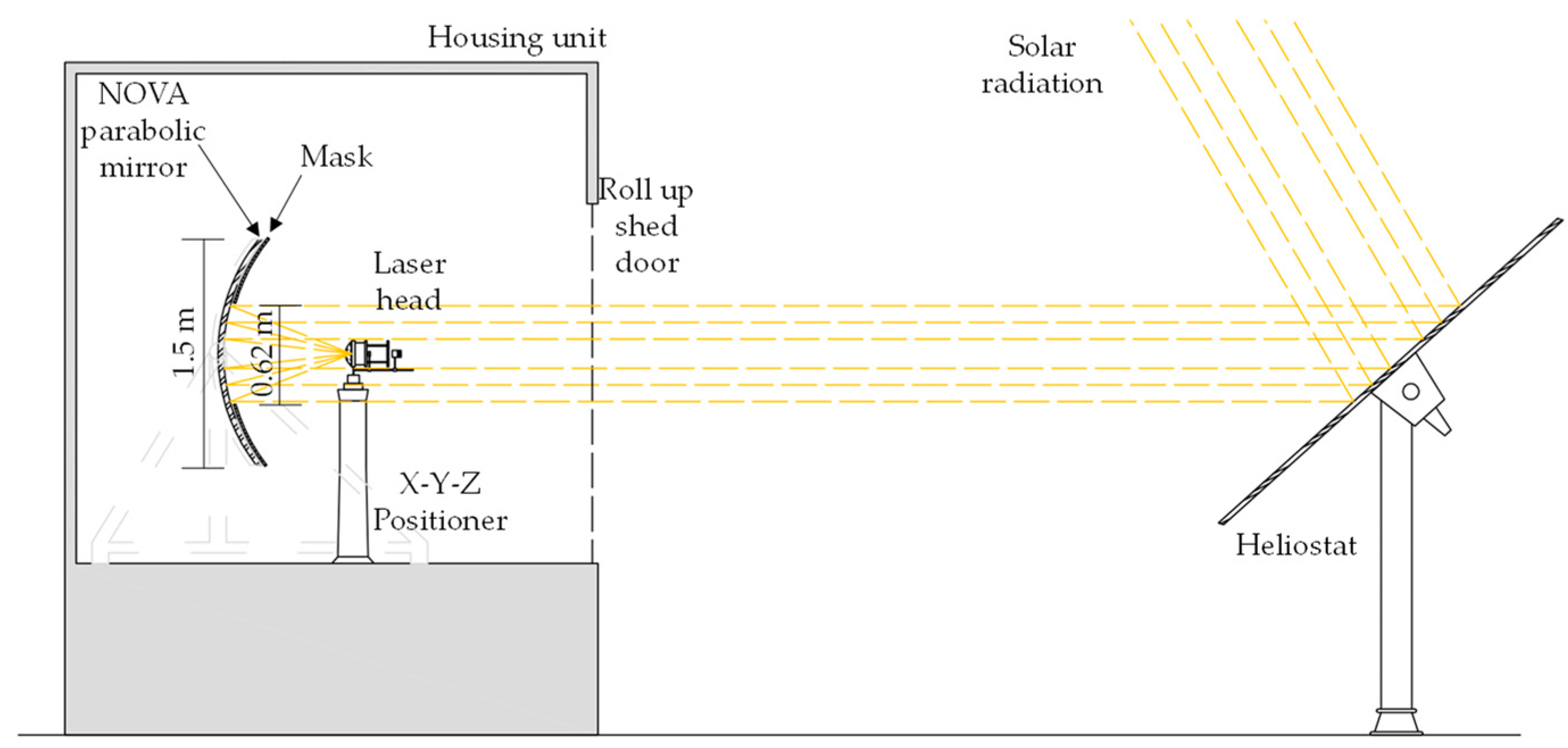
2.1. Solar Energy Collection and Concentration: NOVA Heliostat-Parabolic System

The NOVA heliostat-parabolic mirror solar laser system, as shown in Figure 1, is composed of a two-axis heliostat with four flat mirrors of 93.5% reflectivity, which are used for redirecting the incoming solar radiation toward a parabolic mirror of 80.0% reflectivity with a focal length of 660 mm. This whole system has a combined reflective capacity of 74.8%. By using an external annular mask, the collection diameter of the parabolic mirror was reduced from 1.50 m to 0.68 m. About 0.293 m2 effective solar collection area was then calculated by discounting the shadowed area of approximately 0.07 m2 caused by the laser head and its supporting mechanics, the X-Y-Z positioner, and the non-reflecting space between the two flat segments of the heliostat.

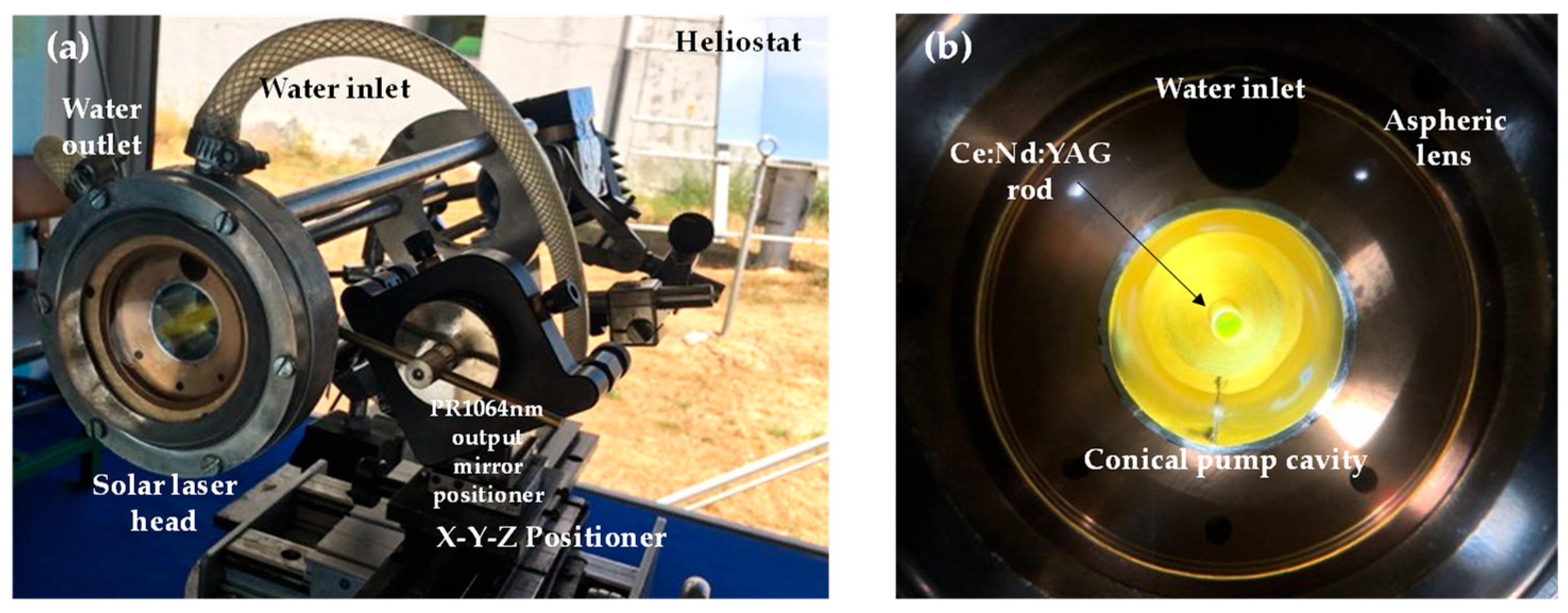
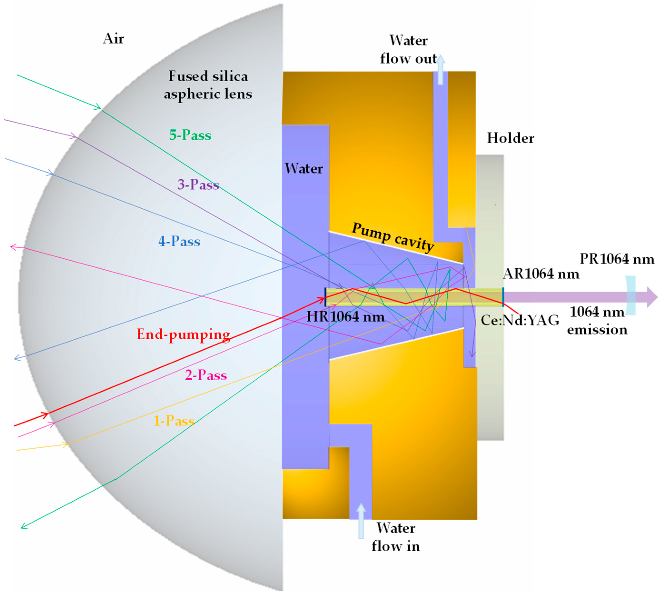
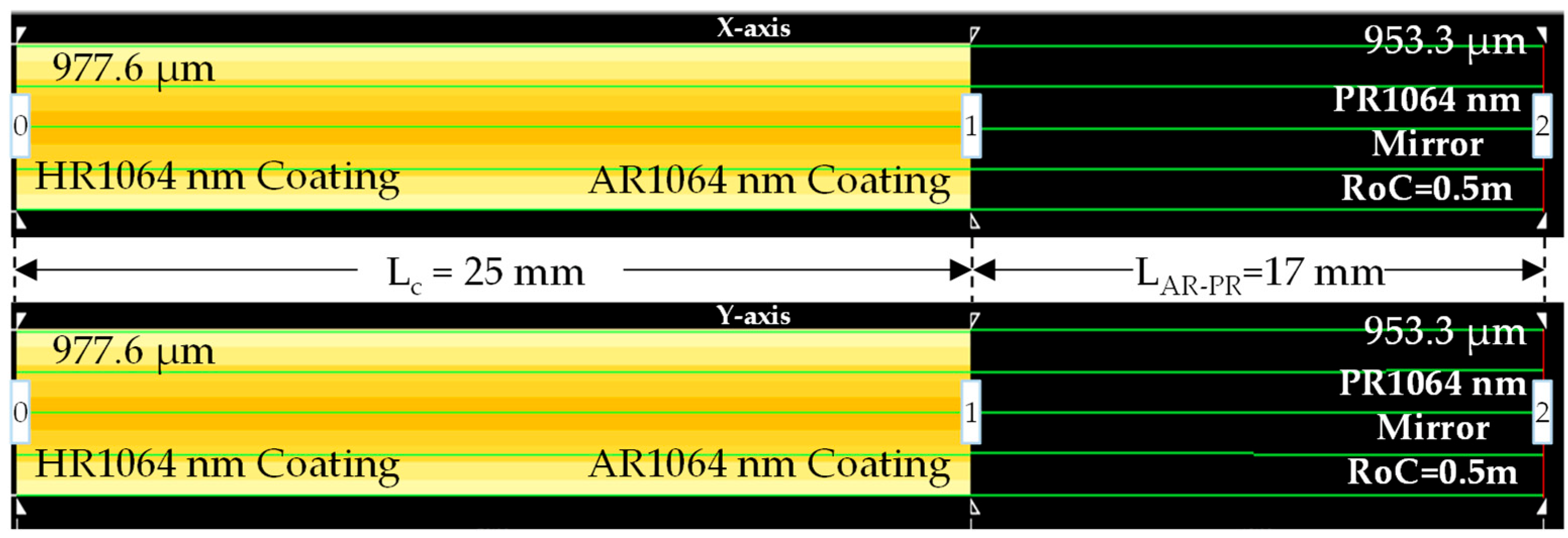
2.2. Solar Laser Head
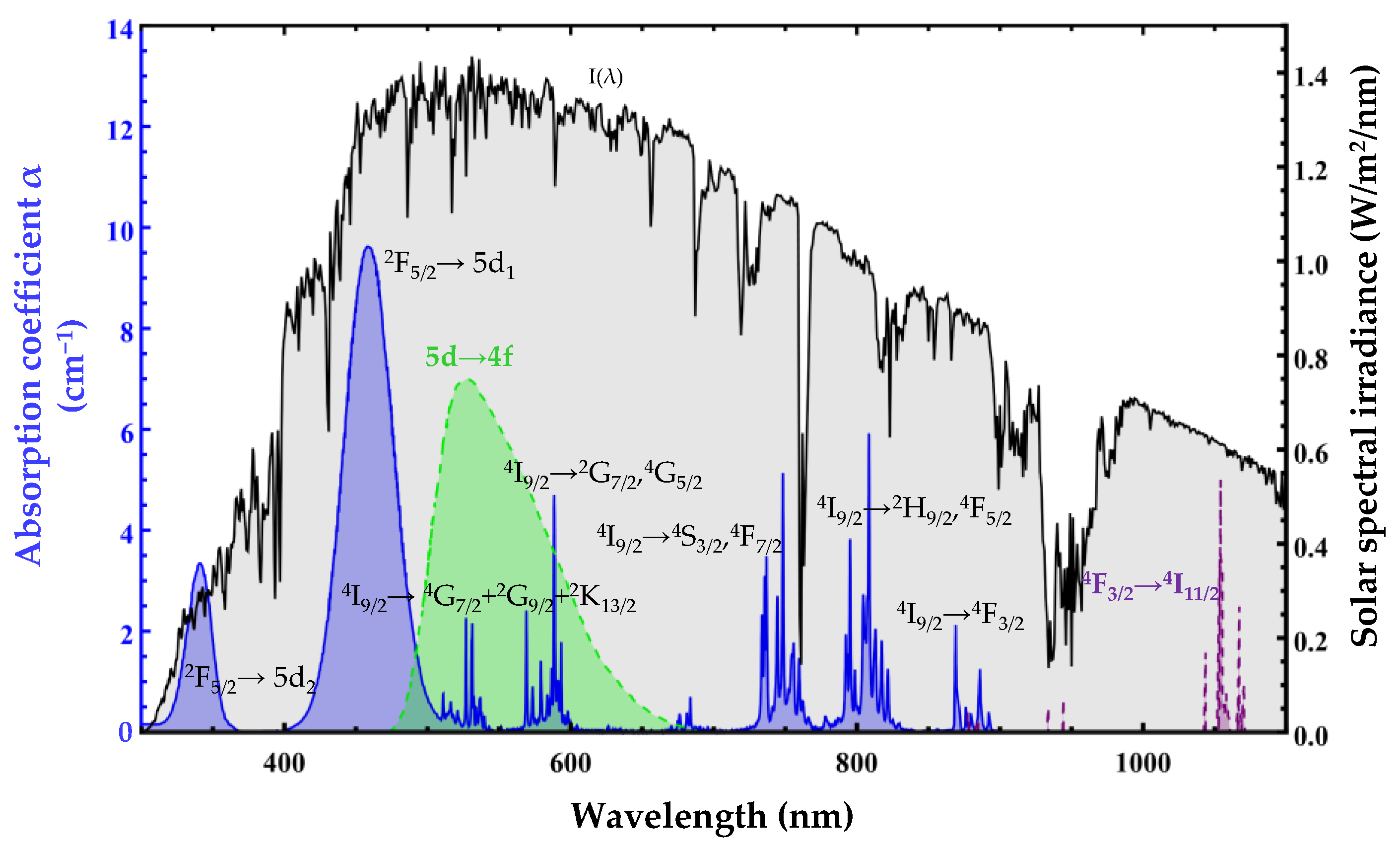
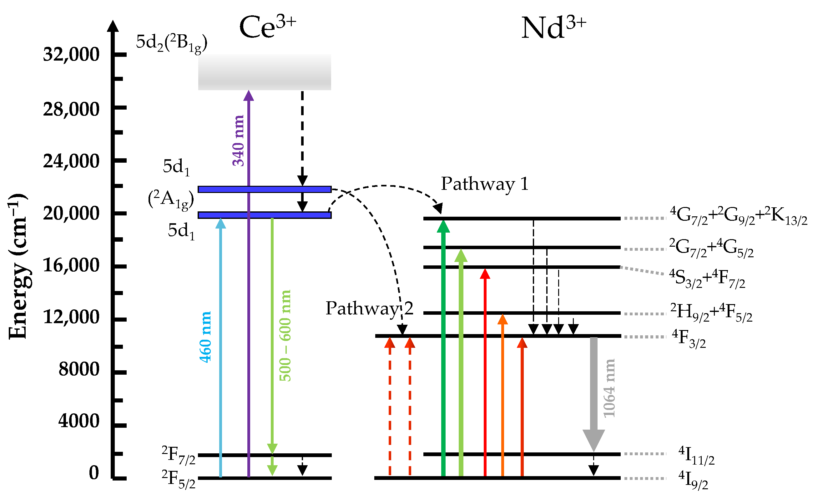
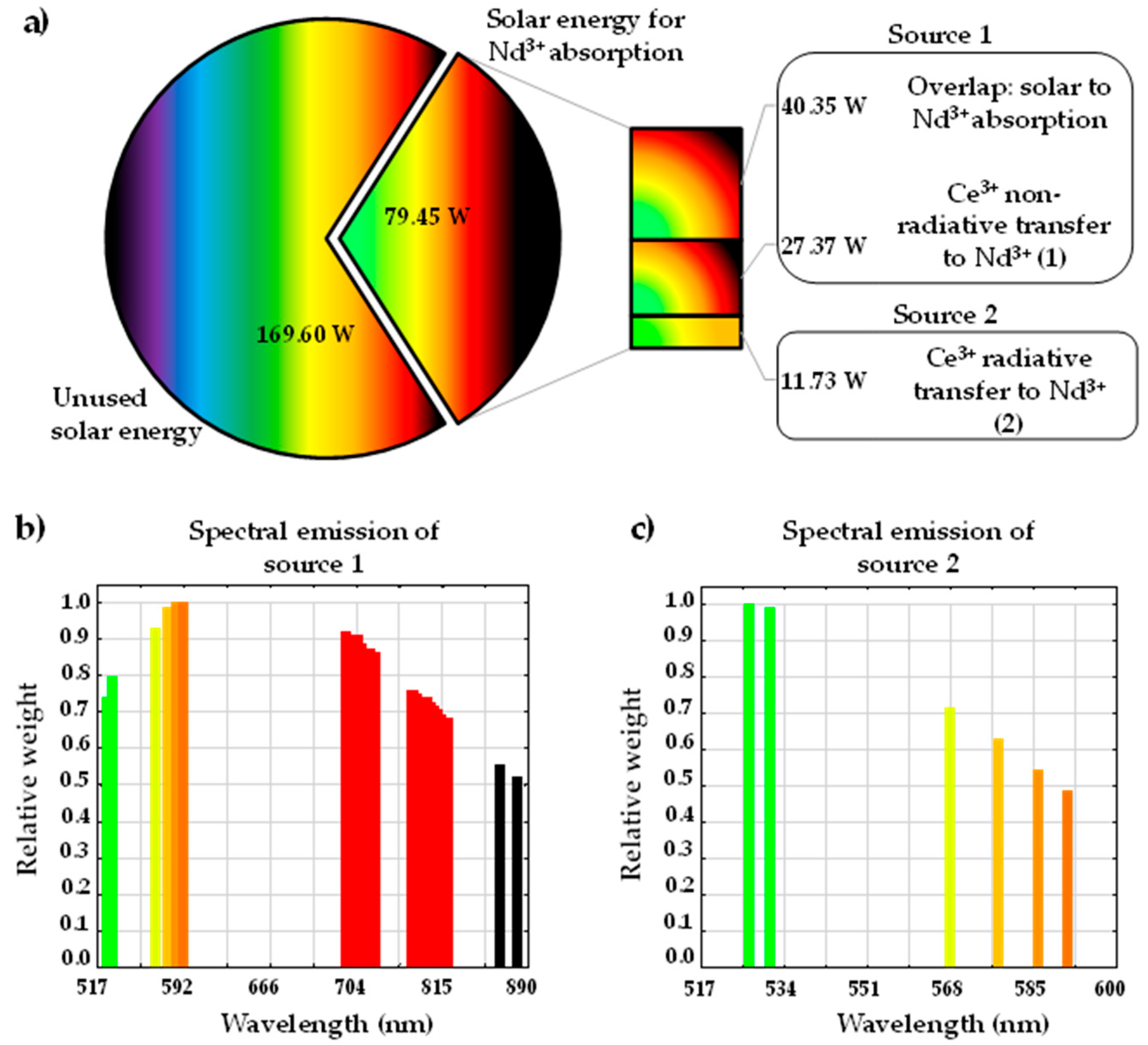
Figure 2 shows the image of the solar laser head and its optical components, as well as the laser resonator components. The laser head was composed of a large fused silica aspheric lens of 99.995% optical purity that focused the concentrated solar radiation onto the flat upper surface of the Ce (0.1 at%):Nd (1.1 at%):YAG rod of 2.5 mm diameter and 25 mm length, mounted within a single reflective conical pump cavity. The rod’s flat upper surface had a highly reflective (HR) coating for the laser emission wavelength at 1064 nm (99.9% @ 1064 nm), while the other end surface had an anti-reflection (AR) coating for the laser emission wavelength (reflectivity (R) < 0.2% @ 1064 nm), supplied by Chengdu, Dongjun Laser Co., Ltd. (Chengdu, China). Cooling water constantly flowed into the laser head from an inlet and the heated water was extracted through the outlet. Maximum lasing could only be achieved when the laser head was correctly aligned at the focus of solar concentrator through the X-Y-Z positioner and the correct alignment of the laser resonator mirrors.
The fused silica aspheric lens had an 82 mm diameter and a thickness of 37 mm, with a curved input surface and a flat output surface. The curved feature of the aspheric lens follows the sag (z) in Equation (1), with radial aperture (r) of 41 mm, the parabolic constant k = 0, the radius of curvature (c) of −43 mm, and the aspheric coefficient 𝛽1 = −0.004.
z = c × r 2 1 + 1 1 + k c 2 r 2 + β 1 r 2 ,
The flat output surface of the lens was 6 mm apart from the flat input surface of the crystal rod. This space was necessary for the laser rod to effectively absorb the concentrated solar radiation and to guarantee an abundant cooling for effective heat dissipation. The absorption efficiency was further enhanced by a silver-coated aluminum foil of 94% reflectivity that covered the conical pump cavity. The reflective conical surface allowed the reabsorption of the solar energy due to the crisscross of the solar rays into the laser rod, thus helping in the redistribution of the solar energy along the rod. This conical pump cavity was 19.5 mm in length with input and output aperture diameters of 18 mm and 9 mm, respectively.
Cooling water with 6 L/min flow rate was used as the heat extraction medium. The cooling system was designed to maximize the removal of the heat generated within the rod and the optical components, such as the fused silica aspheric lens and the conical pump cavity. Both the cooling water and the silica lens weaken the intensity of the UV solarization and IR heating arriving at the rod, which help to reduce the thermal lensing issue.

3. Theory

Energy Transfer Mechanism between Ce3+ and Nd3+ Ions in YAG

The study of Ce3+ ion doped in Nd:YAG under broadband pumping has been a topic of research for decades, starting in 1969 by Holloway et al. [26]. In 1987, Mares et al. studied the energy transfer mechanism between Ce3+ and Nd3+ in YAG at low temperatures [27]. Later in 2015, Tai et al. explored the mechanism of energy transfer of Ce3+ to Nd3+ in YAG with quantum cutting [28]. Its recent use in 2021 by Vistas et al., as a substitute of Nd:YAG in solar-pumped lasers, has shown promising results, achieving about 1.6 times more collection efficiency and solar-to-laser power conversion efficiency compared to that with Nd:YAG crystal rod under the same conditions [22].
The direct solar spectrum, the Ce:Nd:YAG absorption spectrum, the Ce3+ and Nd3+ ions’ emission bands in YAG are presented in Figure 3. The broad absorption bands of the Ce3+ ion is located at the most energetic region of the electromagnetic spectrum, between 315 nm and 510 nm, corresponding to the excited energy level of 5d2 (centered at 339 nm) and 5d1 (centered at 460 nm) [28]. While the Nd3+ absorption bands are in between 510 nm and 888 nm, with five prominent absorbing bands, 4G7/2 + 2G9/2 + 2K13/2 (centered at 530 nm), 2G7/2 + 4G5/2 (centered at 580 nm), 4S3/2 + 4F7/2 (centered at 770 nm), 2H9/2 + 4F5/2 (centered at 805 nm), and 4F3/2 (centered at 878 nm) [29].
The strong UV and blue photons excite the Ce3+ 4f level (the 2F5/2 ground state), toward the 5d sublevels of 5d1 and 5d2, as shown in Figure 4 [28,32]. The consequent energy relaxation from 5d1 to both ground states 2F7/2 and 2F5/2 forms a yellow/green broad emission spectrum, overlapping with the excitation peaks of the Nd3+ ion at the 4G7/2 + 2G9/2 + 2K13/2 energy levels between 510 nm and 540 nm and the 2G7/2 + 4G5/2 energies levels between 566 nm and 595 nm [28,33]. The radiative transfer mechanism by the transition 5d→4f of the Ce3+ ion and the transitions 4I9/24G7/2 + 2G9/2 + 2K13/2 and 4I9/22G7/2 + 4G5/2 through cross-relaxation process are indicated by pathway (1) in Figure 4 [28]. The pathway (2) represents the energy transfer from the Ce3+ excited state at 5d1 to the two Nd3+ ions at 4F3/2 level through quantum cutting down-conversion process [28].
The total absorbed solar power of an ion (Pabs,ion) of the active medium is calculated through Equation (2).
P a b s , i o n = λ i λ f I λ 1 e α i o n λ × L c d λ ,
I(λ) is the solar spectral irradiance (W/m2/nm) of each wavelength λ, Lc is the effective absorption length of the laser rod and αion(λ) is the absorption coefficient of the ion for each wavelength. To effectively calculate the total power available from the Sun to feed both ions, Lc must be considered infinite. In this case, the total absorbed power by Ce3+ (Pabs,Ce) and Nd3+ (Pabs,Nd) ions is approximately 157 W and 162 W, respectively. Given the total solar irradiance of 1000 W/m2, by integrating all the solar wavelength intensities, the overlap efficiency, i.e., the fraction of the available solar power that is absorbed by the Ce3+ (ηoverlap,Ce) and Nd3+ (ηoverlap,Nd) ions, is about 15.7% and 16.2%, respectively, as calculated through Equation (3).
η o v e r l a p , i o n = P a b s , i o n I λ d λ ,
The energy transfer efficiency of the non-radiative process (ηNR:Ce-Nd) is about 70% [28,34], whereas for the radiative process (ηR:Ce-Nd) is about 30% [28].

4. Calculation

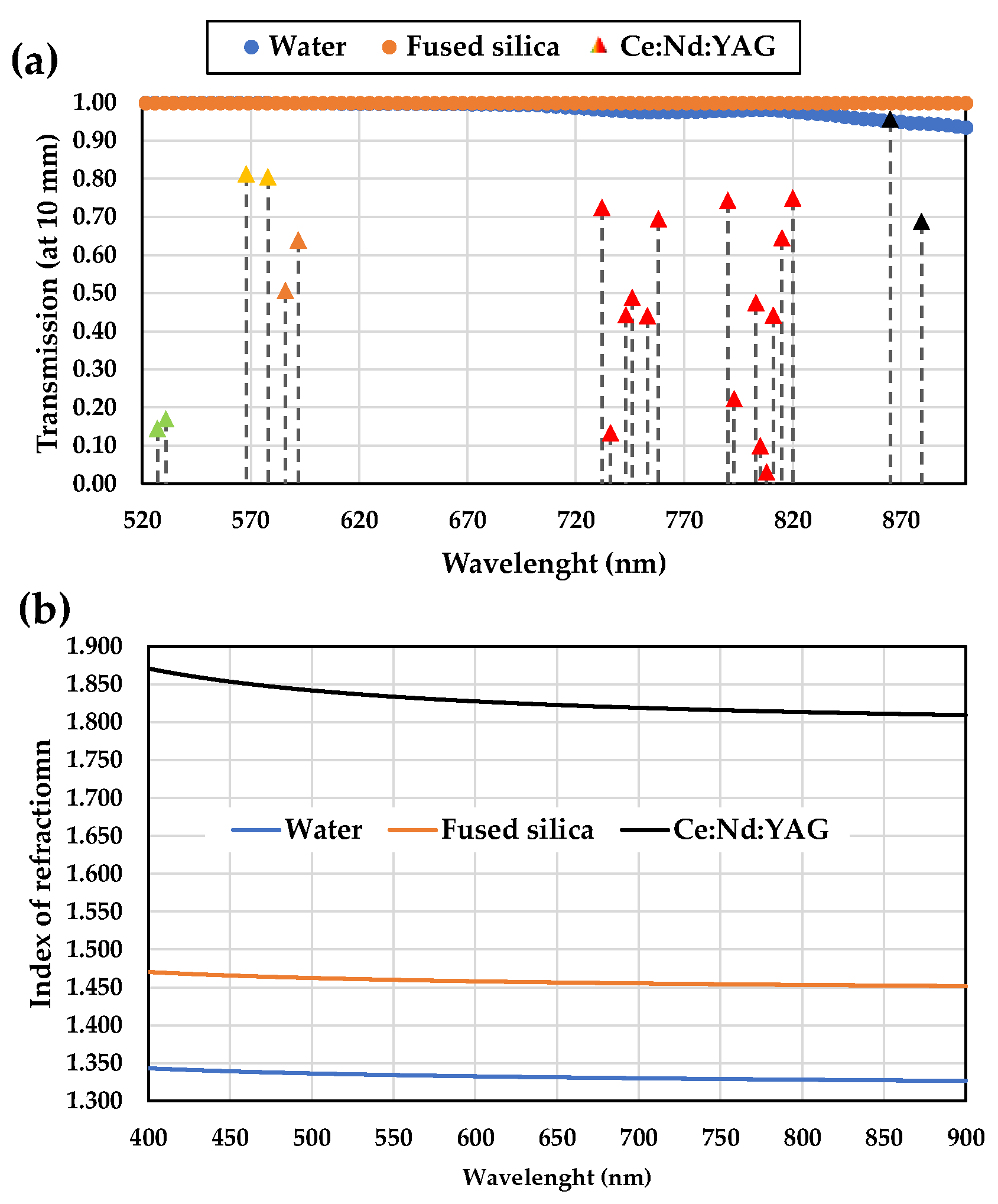
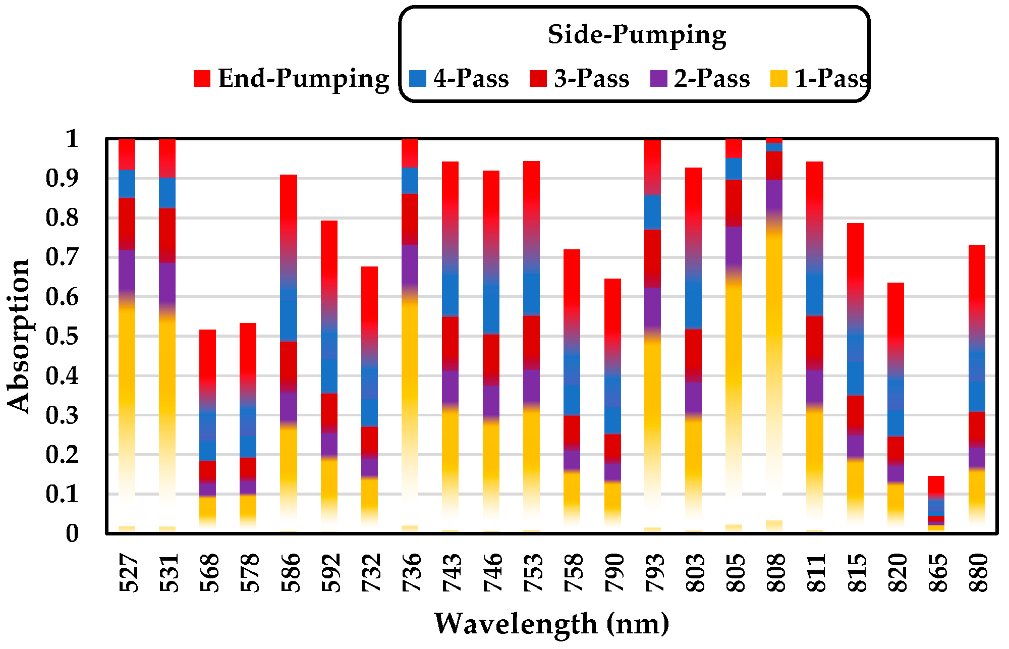
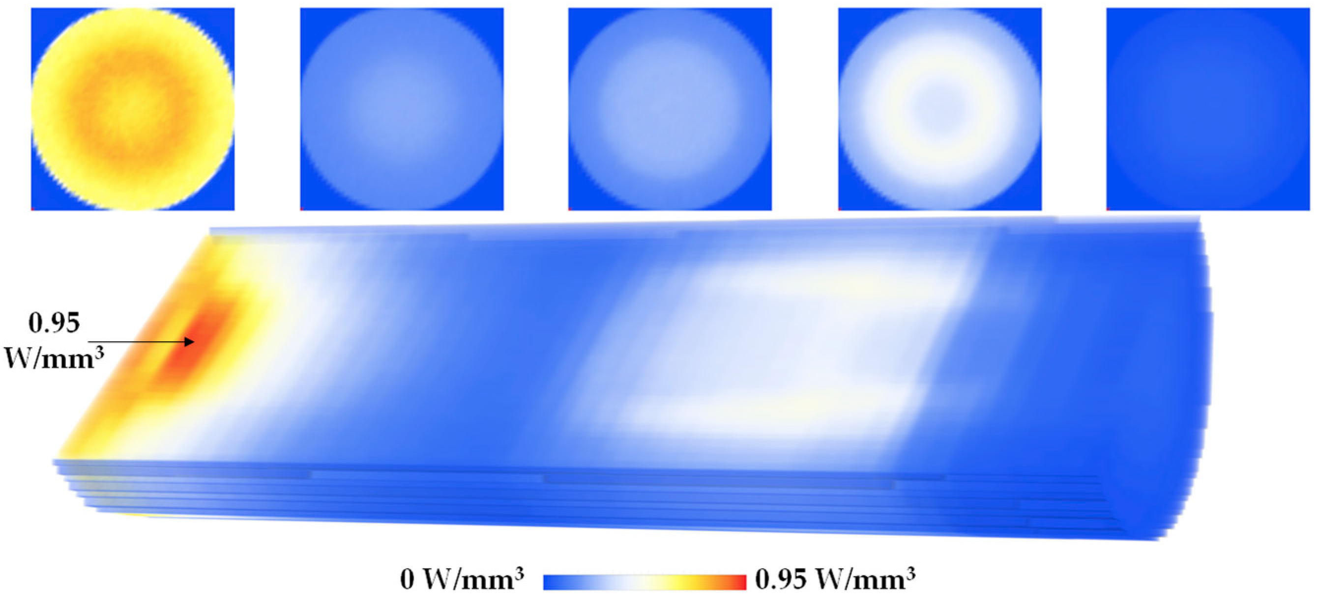
4.1. Zemax© Simulation

There are many possible and viable ways to calculate the absorbed power within the Ce:Nd:YAG with the prevalent wavelengths in the Zemax© software. A direct approach for calculation consists of using all the wavelengths of both the solar emission and the Ce:Nd:YAG absorption spectra. However, this method would require much more computing resources to achieve the same results as those by simulating with a few key solar wavelengths related to the absorption bands responsible for lasing [35].
A total available solar power of 249.05 W can be obtained by the NOVA parabolic mirror with an effective collection area (A) of 0.293 m2, at 850 W/m2 solar irradiance (I). However, only 16.2% and 15.7% of the total power calculated from Equation (3) are useful for calculating the absorbed power by the Ce:Nd:YAG rod with finite dimensions. Consequently, in Zemax©, two sources were defined for solar pumping. The energy division is shown in Figure 5a.
Source 1 emits all the relevant overlapped wavelengths of the solar spectrum with the Nd3+ ion absorption spectrum, as well as the wavelength data that includes the Ce3+ quantum cutting down conversion of non-radiative transfer to Nd3+, described by Pathway (1), as shown in Figure 5b. The simulated power of source 1 (Psource1) follows the Equation (4) and has a total power of 67.72 W.
P s o u r c e   1 = A   I   η o v e r l a p , N d 3 +   + η o v e r l a p , C e 3 +   × η N R : C e N d ,
Source 2 accounts for 30% of the absorbed energy by Ce3+ that was transferred radiatively to Nd3+, as shown in Figure 4 by Pathway (2). This source emits green and orange wavelengths useful for Nd3+ absorption, as shown in Figure 5c. The simulated power of source 2 (Psource2) follows the Equation (5) and has a total power of 11.73 W.
P s o u r c e   2 = A   I   η o v e r l a p , C e 3 +   × η R : C e N d ,
The amount of energy retained within the Ce (0.1 at%):Nd (1.1 at%):YAG depends on the transmission (T) data of the Nd3+ active ion, water and silica materials, shown in Equation (6).
T λ = e α λ × L c ,
Figure 6a shows the transmission data of water and fused silica materials from Zemax© glass catalog, as well as the 22 transmission wavelengths of Ce (0.1 at%):Nd (1.1 at%):YAG, at Lc = 10 mm. Figure 6b shows the index of refraction of Ce (0.1 at%):Nd (1.1 at%):YAG, water and fused silica as a function of the wavelength utilized in Zemax©.
The transmission and the refractive index of the optical materials, the shape of each optical apparatus, the solar wavelengths and the angle of the concentrated solar rays determine the optical path of the solar rays from the source to the crystal rod. Figure 7 shows the optical path of the concentrated solar rays arriving at the laser head, through the fused silica aspheric lens, then into the cooling water and finally to the Ce:Nd:YAG crystal rod. Most of the concentrated solar rays enter the laser rod through its upper HR1064 nm end face, and travel within the rod through total internal reflection (due to the refractive index differences between the water and the active medium), as shown in Figure 7 by the red ray. Side-pumping occurs when rays enter the rod through its lateral surface. Multiple passes can be achieved by a single ray zigzagging back into the crystal through the conical pump cavity, which increases the path length of the ray inside the rod, Lp, and hence the amount of energy absorbed.
Figure 8 shows the absorption of the laser rod as a function of the wavelength and the number of passes. The end-pump has a minimum Lp of 25 mm, the same as the length of the rod. The average Lp of 1-pass, 2-pass, 3-pass, 4-pass, and end-pumping is about 3.25 mm, 6.50 mm, 9.75 mm, 13 mm, and 35 mm, respectively. The absorption of a single ray increases gradually with each successive number of passes within the crystal. Some wavelengths, such as 527 nm, 531 nm, 736 nm, 793 nm, 805 nm, and 808 nm are totally absorbed by the rod if the ray is traveling within the rod by end-pumping regime.
In Zemax©, the Ce (0.1 at%):Nd (1.1 at%):YAG rod was divided into 125,000 voxels. The pump flux distribution along its longitudinal cross-section and five central transversal cross-sections are shown in Figure 9. Red color represents the maximum solar energy absorption, whereas blue represents little or no absorption. The most intensive absorbing region has a peak flux of 0.95 W/mm3, located slightly below the input surface of the rod. The lower part of the rod also absorbs some radiation due to multiple passages of the solar rays by side-pumping with the help of the reflective cone. A total absorbed solar energy of 30.96 W was stored along the thermally loaded crystal.

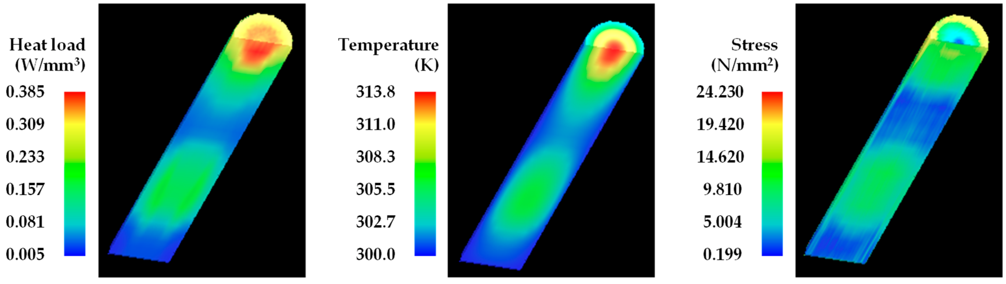
4.2. LASCAD™ Simulation

The absorbed power in cubic matrix form was imported into the laser cavity analysis and design (LASCAD™) software to analyze the solar laser output performance. The material data of Ce (0.1 at%):Nd (1.1 at%):YAG crystal with a stimulated emission cross-section of 2.8 × 10⁻¹⁹ cm2, a fluorescence lifetime of 230 µs and an absorption/scattering loss of 0.002 cm−1 was set in LASCAD™. The mean absorbed and intensity-weighted wavelength of 660 nm was considered in the analysis [11]. Figure 10 shows the laser resonator of the thermally loaded crystal rod and the associated dielectric lenses. The left end-face of the rod has a layer of HR 1064 mm coating, represented by the optical dielectric interface 0. The output end-face has an AR 1064 nm coating, represented by the optical dielectric interface 1. The partial reflection (PR) output mirror is positioned 17 mm apart from the AR coated end face (LAR-PR = 17 mm), represented by optical dielectric interface 2. Different reflectivities and radii of curvature (RoC) of the PR mirror were tested to find the best combination to achieve the highest laser output power for the most efficiently solar-pumped Ce:Nd:YAG rod. A total round-trip loss of 1.6% was accounted in the LASCAD™ calculation.
Figure 11 shows the heat load, the temperature, and the stress intensity of the 2.5 mm diameter, 25 mm length rod numerically calculated through LASCAD™ analysis, under ambient temperature and cooling boundary condition of 300 K. The maximum heat load of 0.385 W/mm3 was locally found. A maximum rod temperature of 313.8 K is attained at the tip of the input surface of the crystal. A moderate maximum thermal stress of 24.23 N/mm2 was found.
During the solar laser experiments, the thin Ce:Nd:YAG rod was cooled by water with a constant flow rate of 6 L/min at 300 K ambient temperature. This allowed the maximum temperature within the crystal to rise no more than just 14 K with the concentrated solar pumping, as shown in Figure 11. According to [36], this temperature variation leads to a decrease in the stimulated emission cross section of only 0.05 × 10⁻¹⁹ cm2 approximately. Hence, its effect on the Nd3+ ions absorption bands is minimal.
Considering all the mentioned physical characteristics of the stimulated active medium, the highest multimode laser power of 11.3 W was numerically calculated with a PR1064 nm of R = 96%, RoC of 0.5 m, as shown in Figure 12. The experimental results are also given.

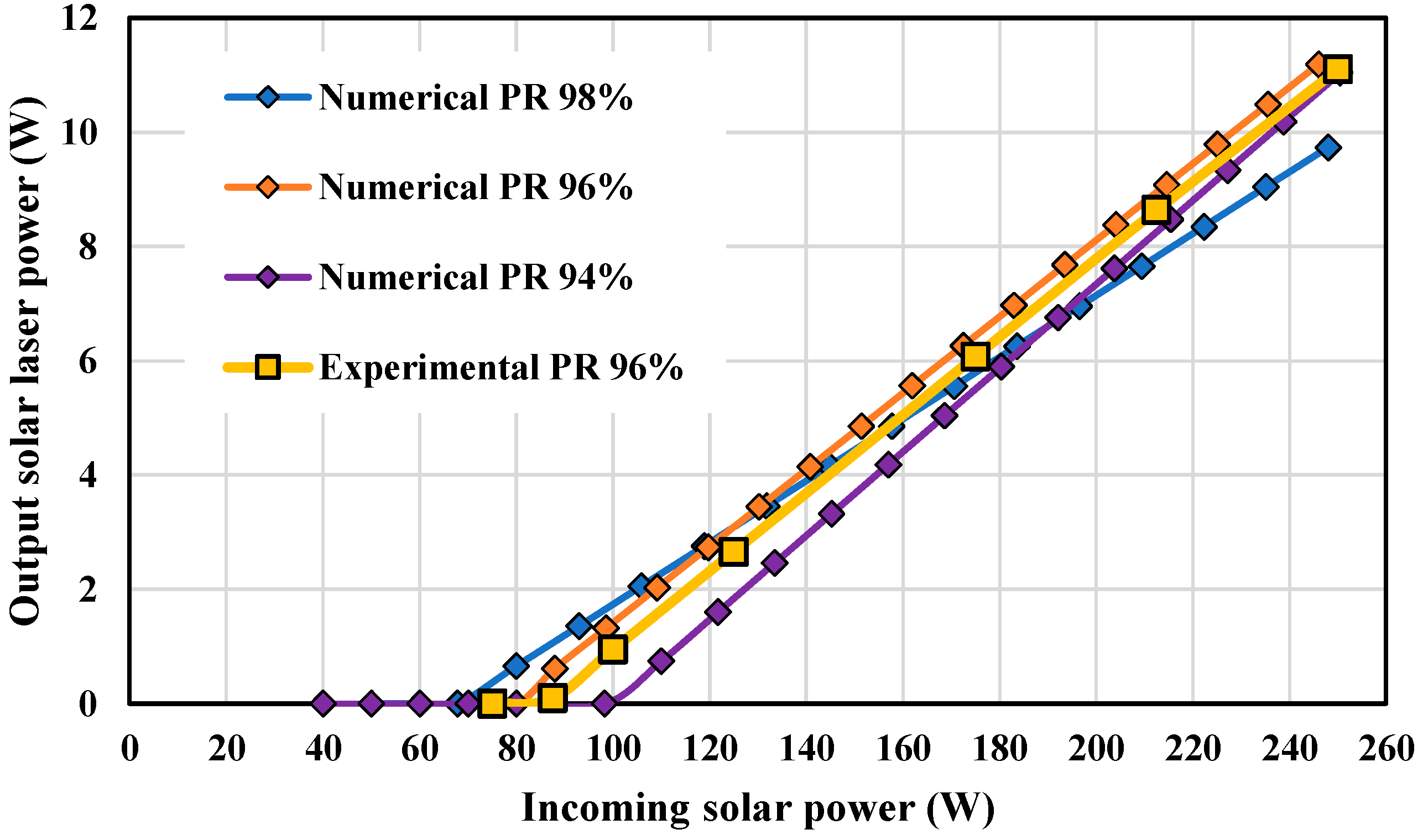
5. Results and Discussion

The solar laser head prototype was built according to the model designed in Zemax© that provided the highest laser power extraction through LASCAD™. The laser head was tested at the NOVA solar facility in April of 2022. The solar irradiance of 850 W/m2 was measured during that period, which is equivalent to a maximum incoming solar power of 249 W provided from the primary parabolic mirror with effective diameter of 0.68 m. A maximum multimode laser power of 11.2 W was successfully achieved using a PR (R ≥ 96% @ 1064 nm) mirror with RoC of 0.5 m, as shown in Figure 12, which matches well with the numerical prediction. The lasing emission started with an incoming solar power of 88 W and grew linearly to 11.2 W at 249 W incoming solar power, leading to a slope efficiency of 6.8%.
Table 1 summarizes the most recent progress in solar-pumped lasers, regarding to the minimum threshold power, maximum solar-to-laser power conversion, solar laser collection, and slope efficiencies.
In this work, only 88 W solar power was needed to start the lasing process, which is 0.44 times below the record minimum threshold power of 200 W [25]. The solar lasing system was able to produce 11.2 W multimode laser power, equivalent to the highest solar-to-laser power conversion efficiency of 4.50%, to the best of our knowledge, which is 1.22 times more than the record of 3.69% [19]. Furthermore, the solar laser collection and slope efficiencies were 38.22 W/m2 and 6.8%, respectively, being 1.18 and 1.02 times higher than the previous records of 32.5 W/m2 and 6.7% through an end-side-pumped Cr:Nd:YAG rod [19].
The laser beam M2 quality factors of the Ce:Nd:YAG were measured according to ISO 11164-1 standards, with a CINOGY UV-NIR beam profiler using a CinCam CMOS. Figure 13a shows the multimode laser beam profile. The measured solar laser beam widths along the beam caustic and the associated extrapolated hyperbolic plot are shown in Figure 13b. Mx2 = 32.16 ± 2.62 and My2 = 36.62 ± 4.22 factors were experimentally obtained.

6. Conclusions

The highly efficient Ce:Nd:YAG solar laser was composed of the first-stage heliostat-parabolic mirror solar energy collection and concentration system; the second-stage fused silica aspheric lens that further concentrated the solar energy onto the end-face of the active medium by end-pumping; and the third-stage conical-shaped reflective pump cavity to efficiently side-pump the 2.5 mm diameter, 25 mm length Ce:Nd:YAG rod. The solar energy transfer for the Nd3+ and Ce3+ ions as well as the energy transfer of Ce3+ to Nd3+ were introduced and considered in Zemax©. The design parameters of the laser head were optimized to find the highest solar energy absorption by the active medium to then determine the best lasing conditions in LASCAD™. The Ce:Nd:YAG solar laser prototype was then built according to the simulated model. 11.2 W multimode laser output power was successfully measured, matching well with the numerical result. This, to the best of our knowledge, resulted in a record solar-to-laser conversion efficiency of 4.50%. The highest solar laser collection and slope efficiencies of 38.22 W/m2 and 6.8%, respectively, were also obtained. Furthermore, low threshold power of 88 W was also reported. Since the NOVA solar energy collection and concentration facility has a limited transfer efficiency of 0.75, further research on small size Ce:Nd:YAG solar laser in direct solar tracking mode will, most hopefully, ensure further solar laser efficiency enhancement and enable promising space applications.

Author Contributions

Conceptualization, D.G.; methodology, D.G.; software, D.G., D.L., C.R.V., H.C. and M.C.; validation, D.G. and D.L.; formal analysis, D.G., D.L., C.R.V. and J.A.; investigation, D.G.; resources, D.L. and J.A.; data curation, D.G. and D.L.; writing—original draft preparation, D.G.; writing—review and editing, D.G., D.L., C.R.V., M.C., B.D.T., H.C. and J.A.; visualization, D.G.; supervision, D.L.; project administration, D.L.; funding acquisition, D.L. All authors have read and agreed to the published version of the manuscript.

Funding

This research was funded by Fundação para a Ciência e a Tecnologia—Ministério da Ciência, Tecnologia e Ensino Superior, grant number UIDB/00068/2020.

Institutional Review Board Statement

Not applicable.

Informed Consent Statement

Not applicable.

Data Availability Statement

Not applicable.

Acknowledgments

The contract CEECIND/03081/2017 and the fellowship grants SFRH/BD/145322/2019, PD/BD/142827/2018, PD/BD/128267/2016 and SFRH/BPD/125116/2016 of Joana Almeida, Miguel Catela, Dário Garcia, Bruno D. Tibúrcio, and Cláudia R. Vistas, respectively, are acknowledged.

Conflicts of Interest

The authors declare no conflict of interest. The funders had no role in the design of the study; in the collection, analyses, or interpretation of data; in the writing of the manuscript, or in the decision to publish the results.

Nomenclature

ACollection area (m2)
cRadius of curvature (mm)
ISolar irradiance (W/m2)
kParabolic constant
Pabs,ionAbsorbed solar power by ion (W)
LcLength rod (mm)
LAR-PRDistance between AR and PR (mm)
rRadial aperture (mm)
RReflectivity
zSag (mm)
Greek symbol
αionAbsorption coefficient (cm−1)
𝛽1Aspheric coefficient (mm−1)
ηoverlap,ionOverlap efficiency
ηNR:Ce-NdNon-radiative conversion efficiency of Ce3+ to Nd3+
λWavelength (nm)
Abbreviation
ARAnti-reflection
HRHigh reflection
LASCAD™Laser cavity analysis and design
MSSFMedium sized solar furnace
PRPartial reflection
RoCRadius of curvature
YAGYttrium aluminum garnet

References

  1. The Global Goals. Goal 7: Affordable and Clean Energy. Available online: https://www.globalgoals.org/goals/7-affordable-and-clean-energy/ (accessed on 1 April 2022).
  2. The Global Goals. Goal 9: Industry, Innovation and Infrastructure. Available online: https://www.globalgoals.org/goals/9-industry-innovation-and-infrastructure/ (accessed on 1 April 2022).
  3. Motohiro, T.; Takeda, Y.; Ito, H.; Hasegawa, K.; Ikesue, A.; Ichikawa, T.; Higuchi, K.; Ichiki, A.; Mizuno, S.; Ito, T.; et al. Concept of the solar-pumped laser-photovoltaics combined system and its application to laser beam power feeding to electric vehicles. Jpn. J. Appl. Phys. 2017, 56, 08MA07. [Google Scholar] [CrossRef]
  4. Yabe, T.; Bagheri, B.; Ohkubo, T.; Uchida, S.; Yoshida, K.; Funatsu, T.; Oishi, T.; Daito, K.; Ishioka, M.; Yasunaga, N.; et al. 100 W-class solar pumped laser for sustainable magnesium-hydrogen energy cycle. J. Appl. Phys. 2008, 104, 083104. [Google Scholar] [CrossRef]
  5. Abdel-Hadi, Y.A. Space-based solar laser system simulation to transfer power onto the earth. NRIAG J. Astron. Geophys. 2020, 9, 558–562. [Google Scholar] [CrossRef]
  6. Kiss, Z.J.; Lewis, H.R.; Duncan, R.C. Sun pumped continuous optical maser. Appl. Phys. Lett. 1963, 2, 93–94. [Google Scholar] [CrossRef]
  7. Insuik, R.J.; Christiansen, W.H. Blackbody-pumped CO2 laser experiment. AIAA J. 1984, 22, 1271–1274. [Google Scholar] [CrossRef]
  8. Terry, C.K.; Peterson, J.E.; Goswami, D.Y. Terrestrial solar-pumped iodine gas laser with minimum threshold concentration requirements. J. Thermophys. Heat Transf. 1996, 10, 54–59. [Google Scholar] [CrossRef]
  9. Lee, J.H.; Kim, K.C.; Kim, K.H. Threshold pump power of a solar-pumped dye laser. Appl. Phys. Lett. 1988, 53, 2021–2022. [Google Scholar] [CrossRef]
  10. Lando, M.; Kagan, J.; Linyekin, B.; Dobrusin, V. A solar-pumped Nd: YAG laser in the high collection efficiency regime. Opt. Commun. 2003, 222, 371–381. [Google Scholar] [CrossRef]
  11. Weksler, M.; Shwartz, J. Solar-Pumped Solid-State Lasers. IEEE J. Quantum Electron. 1988, 24, 1222–1228. [Google Scholar] [CrossRef]
  12. Yabe, T.; Ohkubo, T.; Uchida, S.; Yoshida, K.; Nakatsuka, M.; Funatsu, T.; Mabuti, A.; Oyama, A.; Nakagawa, K.; Oishi, T.; et al. High-efficiency and economical solar-energy-pumped laser with Fresnel lens and chromium codoped laser medium. Appl. Phys. Lett. 2007, 90, 261120. [Google Scholar] [CrossRef]
  13. Liang, D.; Almeida, J. Highly efficient solar-pumped Nd:YAG laser. Opt. Express 2011, 19, 26399–26405. [Google Scholar] [CrossRef] [PubMed]
  14. Dinh, T.H.; Ohkubo, T.; Yabe, T.; Kuboyama, H. 120 watt continuous wave solar-pumped laser with a liquid light-guide lens and an Nd:YAG rod. Opt. Lett. 2012, 37, 2670–2672. [Google Scholar] [CrossRef] [PubMed]
  15. Zhao, B.; Zhao, C.; He, J.; Yang, S. Study of active medium for solar-pumped solid-state lasers. Guangxue Xuebao Acta Opt. Sin. 2007, 27, 1797–1801. [Google Scholar]
  16. Yagi, H.; Yanagitani, T.; Yoshida, H.; Nakatsuka, M.; Ueda, K.-I. Highly Efficient Flashlamp-Pumped Cr3+ and Nd3+ Codoped Y3Al5O12 Ceramic Laser. Jpn. J. Appl. Phys. 2006, 45, 133. [Google Scholar] [CrossRef]
  17. Payziyev, S.; Makhmudov, K.; Abdel-Hadi, Y.A. Simulation of a new solar Ce:Nd:YAG laser system. Optik 2018, 156, 891–895. [Google Scholar] [CrossRef]
  18. Liang, D.; Almeida, J.; Guillot, E. Side-pumped continuous-wave Cr:Nd:YAG ceramic solar laser. Appl. Phys. B 2013, 111, 305–311. [Google Scholar] [CrossRef]
  19. Liang, D.; Vistas, C.R.; Tibúrcio, B.D.; Almeida, J. Solar-pumped Cr:Nd:YAG ceramic laser with 6.7% slope efficiency. Sol. Energy Mater. Sol. Cells 2018, 185, 75–79. [Google Scholar] [CrossRef]
  20. Vistas, C.R.; Liang, D.; Garcia, D.; Almeida, J.; Tibúrcio, B.D.; Guillot, E. Ce:Nd:YAG continuous-wave solar-pumped laser. Optik 2020, 207, 163795. [Google Scholar] [CrossRef]
  21. Li, Y.; Zhou, S.; Lin, H.; Hou, X.; Li, W. Intense 1064 nm emission by the efficient energy transfer from Ce3+ to Nd3+ in Ce/Nd co-doped YAG transparent ceramics. Opt. Mater. 2010, 32, 1223–1226. [Google Scholar] [CrossRef]
  22. Vistas, C.R.; Liang, D.; Almeida, J.; Tibúrcio, B.D.; Garcia, D.; Catela, M.; Costa, H.; Guillot, E. Ce:Nd:YAG side-pumped solar laser. J. Photonics Energy 2021, 11, 1–9. [Google Scholar] [CrossRef]
  23. Vistas, C.R.; Liang, D.; Garcia, D.; Catela, M.; Tibúrcio, B.D.; Costa, H.; Guillot, E.; Almeida, J. Uniform and Non-Uniform Pumping Effect on Ce:Nd:YAG Side-Pumped Solar Laser Output Performance. Energies 2022, 15, 3577. [Google Scholar] [CrossRef]
  24. Almeida, J.; Liang, D.; Garcia, D.; Tibúrcio, B.D.; Costa, H.; Catela, M.; Guillot, E.; Vistas, C.R. 40 W Continuous Wave Ce:Nd:YAG Solar Laser through a Fused Silica Light Guide. Energies 2022, 15, 3998. [Google Scholar] [CrossRef]
  25. Guan, Z.; Zhao, C.; Li, J.; He, D.; Zhang, H. 32.1 W/m2 continuous wave solar-pumped laser with a bonding Nd:YAG/YAG rod and a Fresnel lens. Opt. Laser Technol. 2018, 107, 158–161. [Google Scholar] [CrossRef]
  26. Holloway, W.W.; Kestigian, M. Optical Properties of Cerium-Activated Garnet Crystals. J. Opt. Soc. Am. 1969, 59, 60–63. [Google Scholar] [CrossRef]
  27. Mares, J.; Jacquier, B.; Pédrini, C.; Boulon, G. Energy transfer mechanisms between Ce3+ and Nd3+ in YAG: Nd, Ce at low temperature. Rev. Phys. Appl. 1987, 22, 145–152. [Google Scholar] [CrossRef]
  28. Tai, Y.; Zheng, G.; Wang, H.; Bai, J. Near-infrared quantum cutting of Ce3+–Nd3+ co-doped Y3Al5O12 crystal for crystalline silicon solar cells. J. Photochem. Photobiol. A Chem. 2015, 303–304, 80–85. [Google Scholar] [CrossRef]
  29. Powell, R.C. Physics of Solid-State Laser Materials; Springer: New York, NY, USA, 1998. [Google Scholar]
  30. ASTM G173-03(2012); Standard Tables for Reference Solar Spectral Irradiances: Direct Normal and Hemispherical on 37° Tilted Surface. ASTM International: West Conshohocken, PA, USA, 2012.
  31. Payziyev, S.; Sherniyozov, A.; Bakhramov, S.; Zikrillayev, K.; Khalikov, G.; Makhmudov, K.; Ismailov, M.; Payziyeva, D. Luminescence sensitization properties of Ce: Nd: YAG materials for solar pumped lasers. Opt. Commun. 2021, 499, 127283. [Google Scholar] [CrossRef]
  32. Ueda, J.; Tanabe, S. (INVITED) Review of luminescent properties of Ce3+-doped garnet phosphors: New insight into the effect of crystal and electronic structure. Opt. Mater. X 2019, 1, 100018. [Google Scholar] [CrossRef]
  33. Samuel, P.; Yanagitani, T.; Yagi, H.; Nakao, H.; Ueda, K.I.; Babu, S.M. Efficient energy transfer between Ce3+ and Nd3+ in cerium codoped Nd: YAG laser quality transparent ceramics. J. Alloys Compd. 2010, 507, 475–478. [Google Scholar] [CrossRef]
  34. Yamaga, M.; Oda, Y.; Uno, H.; Hasegawa, K.; Ito, H.; Mizuno, S. Energy transfer from Ce to Nd in Y3Al5O12 ceramics. Phys. Status Solidi C 2012, 9, 2300–2303. [Google Scholar] [CrossRef]
  35. LAS-CAD GmbH. LASCAD, 3.3.5 Manual; LAS-CAD GmbH: Munchen, Germany, 2007. [Google Scholar]
  36. Dong, J.; Rapaport, A.; Bass, M.; Szipocs, F.; Ueda, K.-I. Temperature-dependent stimulated emission cross section and concentration quenching in highly doped Nd3+: YAG crystals. Phys. Status Solidi A 2005, 202, 2565–2573. [Google Scholar] [CrossRef]
Figure 1. Schematic of the NOVA heliostat-parabolic mirror solar energy collection and concentration system.
Energies 15 05292 g001
Figure 2. Photograph of (a) the Ce (0.1 at%):Nd (1.1 at%):YAG solar laser head at the focus of the parabolic mirror, and (b) the front view of the laser head.
Energies 15 05292 g002
Figure 3. AM1.5 direct solar spectrum (black), adapted from [30]. Ce (0.1 at%):Nd (1.1 at%):YAG absorption spectrum (blue), Ce3+ (green) and Nd3+ (purple) emission spectra in YAG, adapted from [31].
Energies 15 05292 g003
Figure 4. Absorption and emission energy level of Ce3+ and Nd3+ ions. (1) The energy transfer by cross relaxation of Ce3+ to Nd3+ ion, and (2) the quantum cutting down conversion of Ce3+ ion from 5d1 energy level into two Nd3+ ions at 4F3/2 energy level. Adapted from [28,29].
Energies 15 05292 g004
Figure 5. (a) Solar energy division for Ce:Nd:YAG absorption from a total of 249.05 W. Spectral composition used in (b) source 1 and (c) source 2.
Energies 15 05292 g005
Figure 6. Materials in Zemax©: Ce (0.1 at%):Nd (0.1 at%):YAG, water and fused silica. (a) Transmission of the materials at 10 mm depth. (b) Index of refraction of the materials at 20 °C and 1 atm.
Energies 15 05292 g006
Figure 7. Solar rays at various angles and wavelengths passing through the Ce:Nd:YAG medium inside the laser head. End-pumping occurs through total internal reflection within the rod. Side-pumping may have 1 to 5 or more passes through the rod.
Energies 15 05292 g007
Figure 8. Wavelength-dependent absorption versus number of passes within the crystal. Each pass covers an average absorption length traveled within the crystal rod.
Energies 15 05292 g008
Figure 9. Absorbed solar pump-flux distribution along the longitudinal at a central cross-section, and five separate transversal cross-sections of the Ce:Nd:YAG rod.
Energies 15 05292 g009
Figure 10. Laser resonator configuration for multimode solar laser extraction from the Ce:Nd:YAG rod. The Lc is the laser rod length, and the LAR-PR is the length between AR1064 nm end face of the rod and the PR1064 nm mirror.
Energies 15 05292 g010
Figure 11. Heat load, temperature, and stress intensity of the 2.5 mm diameter, 25 mm length Ce:Nd:YAG rod, numerically acquired through LASCAD™ analysis.
Energies 15 05292 g011
Figure 12. Ce:Nd:YAG solar laser output power as a function of the incoming solar power, numerically obtained using partial reflection (PR) mirror of 94%, 96%, and 98% and experimentally achieved with PR 96%.
Energies 15 05292 g012
Figure 13. (a) Multimode beam profile. (b) Caustic fit measurements of the multimode solar laser beam along the X-axis (red color) and Y-axis (blue color).
Energies 15 05292 g013
Table 1. Comparison of progress in solar efficiencies.
ParametersGuan et al. 2018 [25]Liang et al. 2018 [19]Vistas et al. 2021 [22]This Work 2022Improvements Over Previous Record (Times)
Primary concentratorFresnel lensParabolic mirrorParabolic mirrorParabolic mirror-
Overall efficiency of the collection system~45%75%75%75%-
Effective collection area1.030 m21.000 m21.070 m20.293 m2-
Tracking methodDirect trackingVia heliostatVia heliostatVia heliostat-
Solar irradiance980 W/m2870 W/m2860 W/m2850 W/m2-
Active medium
Pumping method
Nd:YAG/YAG
End-side-pump
Cr:Nd:YAG
End-side-pump
Ce:Nd:YAG
Side-pump
Ce:Nd:YAG
End-side-pump
-
Laser power31.1 W32.5 W16.5 W11.2 W-
Minimum incoming threshold power200 W400 W220 W88 W0.44 [25]
Solar-to-laser conversion efficiency3.1%3.7%2.8%4.5%1.22 [19]
Solar laser collection efficiency32.1 W/m232.5 W/m223.6 W/m238.22 W/m21.18 [19]
Slope efficiency5.4%6.7%4.4%6.8%1.02 [19]
Publisher’s Note: MDPI stays neutral with regard to jurisdictional claims in published maps and institutional affiliations.

