Article

Control Strategy of Dual-Winding Motor for Vehicle Electro-Hydraulic Braking Systems

1
Department of Electrical Engineering, Hanyang University, 222, Wangsimni-ro, Seongdong-gu, Seoul 04763, Korea
2
SW2 Lab, Software Campus, Mando Corp, 21, Pangyo-ro 255beon-gil, Bundang-gu, Seongnam-si 13486, Korea
*
Author to whom correspondence should be addressed.
Energies 2022, 15(14), 5090; https://doi.org/10.3390/en15145090
Submission received: 24 June 2022 / Revised: 8 July 2022 / Accepted: 9 July 2022 / Published: 12 July 2022

Abstract

:
The electro-hydraulic brake (EHB) system of a vehicle should operate normally under all circumstances to ensure automotive safety. This redundant system guarantees the minimum required performance in the event of a critical failure of the brake system. In this study, we propose a redundant motor control strategy for the EHB to fully realize a functional safety design. The EHB system is composed of two identical electronic control units (ECUs), a dual three-phase dual-winding permanent magnet synchronous motor (DW-PMSM), and hydraulic components to generate brake pressure through the movement of an actuator. First, we propose a method to acquire the necessary motor current for generating brake pressure. Second, we present an initial driving method for the DW-PMSM for achieving stability before generating the braking pressure that involves setting the actuator’s origin position without a position sensor. Lastly, we describe a redundant motor control strategy for continuous brake operation depending on whether each ECU experiences system failure. The experimental results showed the effectiveness and feasibility of the control strategy of the dual-winding motor for a functional safety design.

1. Introduction

As the driving performance of vehicles is continuously improved using electronic control systems, their functional safety issues have gained importance, and it has become necessary to develop brake systems that are in strict compliance with safety requirements. Furthermore, throughout the lifespan of a safety-critical system, safety measures should be given the greatest priority. The ISO-26262 functional safety standard was designed to ensure the development of safety-oriented systems [1,2]. Given these circumstances, all brake systems must maintain the above-mentioned strict functional safety standards, especially during driving. Hence, various types of brake systems, as well as the electric vacuum pump (EVB), electro-mechanical brake booster (EMBB), and electro-hydraulic brake (EHB), have been produced. The EVB system consists of an extra electric vacuum pump that acts as the vacuum source to substitute for the combustion engine in electric vehicles (EVs), which results in a bulky and expensive brake system [3,4]. The EMBB system is a brake aid actuator that boosts the driver’s pedal power independently of the vacuum source, enabling active braking for highly automated driving (HAD). However, several calibrations are necessary to account for the EMBB system’s significant nonlinearities and load-dependent friction in position control [5]. The EHB is a hybrid electro-hydraulic system, in which electronic parts replace some of the mechanical components of the original brake system [6,7]. The brake pedal and wheel calipers are separated from the EHB system to generate pedal force feedback, providing a pedal feel that is independent of the operating environment of the brake system. In addition to operator comfort, the EHB enables the continuous control of each caliper pressure [8,9]. EHB systems, as opposed to typical braking systems using vacuum boosters, allow for faster response times and smaller sizes [10]. A faster response helps active safety systems, such as electronic stability control, work better [11]. However, EHB systems have no option but to stop the vehicle by pressing on the driver’s pedaling force in cases of a system failure, such as hydraulic leakage or electrical malfunction. In this situation, the braking power may be insufficient to cope with an accident, especially when the vehicle is driven at high speeds. To overcome this safety state, a redundant design is typically suggested as a solution. Dual three-phase motors are used in such redundant systems, and dual electrical control units (ECUs) are constructed as two electrically separated units. The redundant brake system requires elementary infrastructure for safe and reliable operation. Redundancy technology is a method for improving the reliability of a motor drive system by adding extra resources, such as hardware or software [12,13,14]. This brake system contains a dual-winding permanent magnet synchronous motor (DW-PMSM). The configuration and drive of the DW-PMSM have been explored extensively in previous studies. The advantages of the DW-PMSM include higher torque, lower torque ripple, lower eddy losses owing to the reduced stator magneto motive force (MMF) harmonic components, and better fault-tolerant capacity [15,16,17,18,19,20].
In this work, we propose a redundant motor control strategy for the EHB to generate and maintain brake pressure for normal or fault conditions, such as a fault in one of the windings. The main aim here was to propose a redundant motor control strategy and ensure continuous control of hydraulic performance for functional safety. As shown in Figure 1a, in the EHB system, when a driver presses the brake pedal, the ECUs measure the physical change in the pedal length through a pedal sensor. Accordingly, the ECUs calculate the required brake pressure and output the appropriate valve command to operate the hydraulic control unit (HCU) and pulse-width modulation (PWM) duty through an inverter to operate the DW-PMSM.
The rotational motion of the motor is converted to a forward motion in the actuator by an internal gear, which generates brake pressure at the wheel cylinder. The position sensor of the pump piston inside the actuator that moves forward and backward is not built-in because position sensors, such as potentiometers and linear variable displacement transducers (LVDTs), have nonlinear characteristics [21,22]. This nonlinearity leads to inaccuracies or errors in measurements. Instead of correcting the nonlinearities in the outputs of these position sensors, we propose a method to operate the actuator without a position sensor by calculating the position of the pump piston according to the internal gear ratio and motor rotation ratio. Failures of the sensors, valves, and inverters of each of the ECUs are detected by the diagnostic function periodically, and the ECU in which the failure occurs limits the control output. Thus, a normally operating ECU performs continuous control. In Figure 1b, each ECU receives power independently of the other, and each acquires separate sensor signals and vehicle information. The upper controller calculates the required brake pressure value and sends the valve commands accordingly. The sub-controller calculates the PWM output value according to the torque command output from the upper controller. For normal operation, each ECU transmits 100% of its output. This enables the creation of maximum pressure in the brake system; thus, if one ECU fails, the remaining ECU maintains 100% of its output so that it can output 50% of its maximum performance under normal conditions. When there is 50% of the required output of this brake system, the sudden braking function of the vehicle is possible.
However, if the brake pressure command required by each ECU is calculated differently under normal operation, the torque command values will be different. Accordingly, different current values are applied to each of the coils of the DW-PMSM, causing non-uniform operation of the motor. To solve this problem, in this work, ECU A is set as the master and ECU B is set as the slave, and the torque command output from the sub-controller is transmitted from the master to the slave through universal asynchronous receiver/transmitter (UART) communication to achieve motor control with the sub-controller commands. The diagnostic function determines whether the sensor status in each ECU is normal. If the diagnostic function detects a fault in the ECU, the PWM is output only from the normal ECU.
In the present study, we explain how to calculate the current command value required for the DW-PMSM to generate brake pressure. Further, we describe a method for setting the initial actuator position throughout the motor operation. In the redundant system, a brake control method for brake operation in the single fault state is presented.

2. Calculation of Required Current Reference of DW-PMSM for Brake Pressure Generation

2.1. Mathematical Model of DW-PMSM

To calculate the value of the motor current required to generate the brake pressure in the EHB system, it is necessary to first analyze the mathematical model of the DW-PMSM to investigate the ratio between current and torque. Brake pressure is created by pushing the incompressible hydraulic pressure inside the actuator according to the motor torque. The voltage equation in the dq frame of the DW-PMSM can be expressed as Equations (1) and (2).
V d k = R a i d k + d λ d k d t ω r λ q k
V q k = R a i q k + d λ q k d t + ω r λ d k
Here, R a is the stator winding resistance; ω r is the angular electrical speed; λ d k and λ q k are the magnetic flux linkages in the dq frame, as expressed in Equations (3) and (4); and the subscript k denotes motor coil-1 and coil-2.
λ d k = L q k i q k + ϕ f
λ q k = L q k i q k
L d k and L q k are the dq-axis self-inductances of each phase; ϕ f is the flux of the permanent magnet. The torque of the DW-PMSM can be obtained from the mechanical output of the motor. In the dq-axis coordinate system, the input power of the DW-PMSM is expressed as Equation (5).
P i n , k = 3 2 V d k i d k + V q k i q k
By substituting Equations (1) to (4) into Equation (5), the result is as follows.
P i n , k   =   3 2 R a i d k 2 + i q k 2 + i d k d λ d k d t + i q k d λ q k d t + ω r ϕ f i q k + ω r L d k L q k i d k i q k
In the above equation, the first two terms are the copper loss, and the next two terms are the variations in the magnetic field energy. The last two terms represent the mechanical output of the motor [23]. PMSMs with concentrated, symmetrically arranged windings of 8-pole and 12-slot combinations have low mutual inductance effects if the battery input voltages and rotor position sensing values of ECUs A and B are the same. Therefore, consideration of mutual electromagnetic coupling between motor coil-1 and coil-2 was excluded. The torque is divided by the angular electrical speed ω r in the last two terms representing mechanical output in Equation (6). Equations (7) and (8) show the electromagnetic torque equations generated by the first ( T 1 ) and second ( T 2 ) winding sets. Accordingly, the total torque is calculated by adding T 1 and T 2 , and P is the number of poles [24].
T 1 = P 2 3 2 ϕ f i q 1 + L d 1 L q 1 i d 1 i q 1
T 2 = P 2 3 2 ϕ f i q 2 + L d 2 L q 2 i d 2 i q 2

2.2. Calculation of Feedforward Current Reference According to Required Brake Pressure

When the d-axis is controlled with zero current ( i d 1 = 0 , i d 2 = 0 ), the total torque equation ( T s u m ) is calculated as follows:
T s u m = T 1 + T 2 = P 2 3 2 ϕ f ( i q 1 + i q 2 )
The torque applied to the DW-PMSM is determined by the current. Therefore, the torque command can be expressed as a current value. The brake pressure is generated according to the current value applied to motor coil-1 and coil-2. In Figure 2a,b, the same current is applied in incremental steps from 0 to 60 A in each ECU. As a result, the pressure generated in the EHB system is as shown in Figure 2c. Thus, the brake pressure that is related to the current applied to the DW-PMSM can be expressed as a linear line, as shown in Figure 2d. I_apply * represents the feedforward current required to increase the pressure. Moreover, I_release* represents the feedforward current required to drop the pressure. Due to the characteristics of the EHB brake system, the value of the current required when the pressure is rising and falling is different. Accordingly, if the brake pressure required by the upper controller is calculated in accordance with the state in which the driver applies the brake, the current value required for the DW-PMSM can be estimated. This current reference value is used as the feedforward term of the sub-controller. The feedforward map of the speed controller has a different feedforward current reference according to the rise and fall of pressure. The feedforward current reference is described in detail in Section 4.

3. Proposed Motor Operation Method for Position Alignment of Actuator

3.1. Actuator Control Mechanism for Brake Pressure Control

As shown in Figure 3a, in the EHB system, when the DW-PMSM rotates, the lead screw converts the rotational motion of the shaft into linear motion. Hence, the pump piston moves forward and backward in the actuator. Based on the mechanical design specifications, it is possible to calculate the pump piston position according to the motor rotation rate. Therefore, if the initial position of the pump piston is set, the position can be calculated continuously according to the angular velocity of the DW-PMSM without the position sensor of the actuator. Thus, the pump piston position can be identified in real time during brake operation. Since the position alignment of the pump piston cannot be performed while the driver is pressing the brake pedal to stop the vehicle, a method to align the initial position of the pump piston at a specific point in time is proposed herein. Once the initial position alignment is completed, when the brake pedal is pressed, the pump piston advances according to the motor rotation, as shown in Figure 3b, to increase the brake pressure. If the driver does not press the pedal, the motor rotates in the opposite direction, and the pump piston moves to its initial position, thereby reducing the brake pressure.

3.2. Proposed Pump Piston Alignment Method

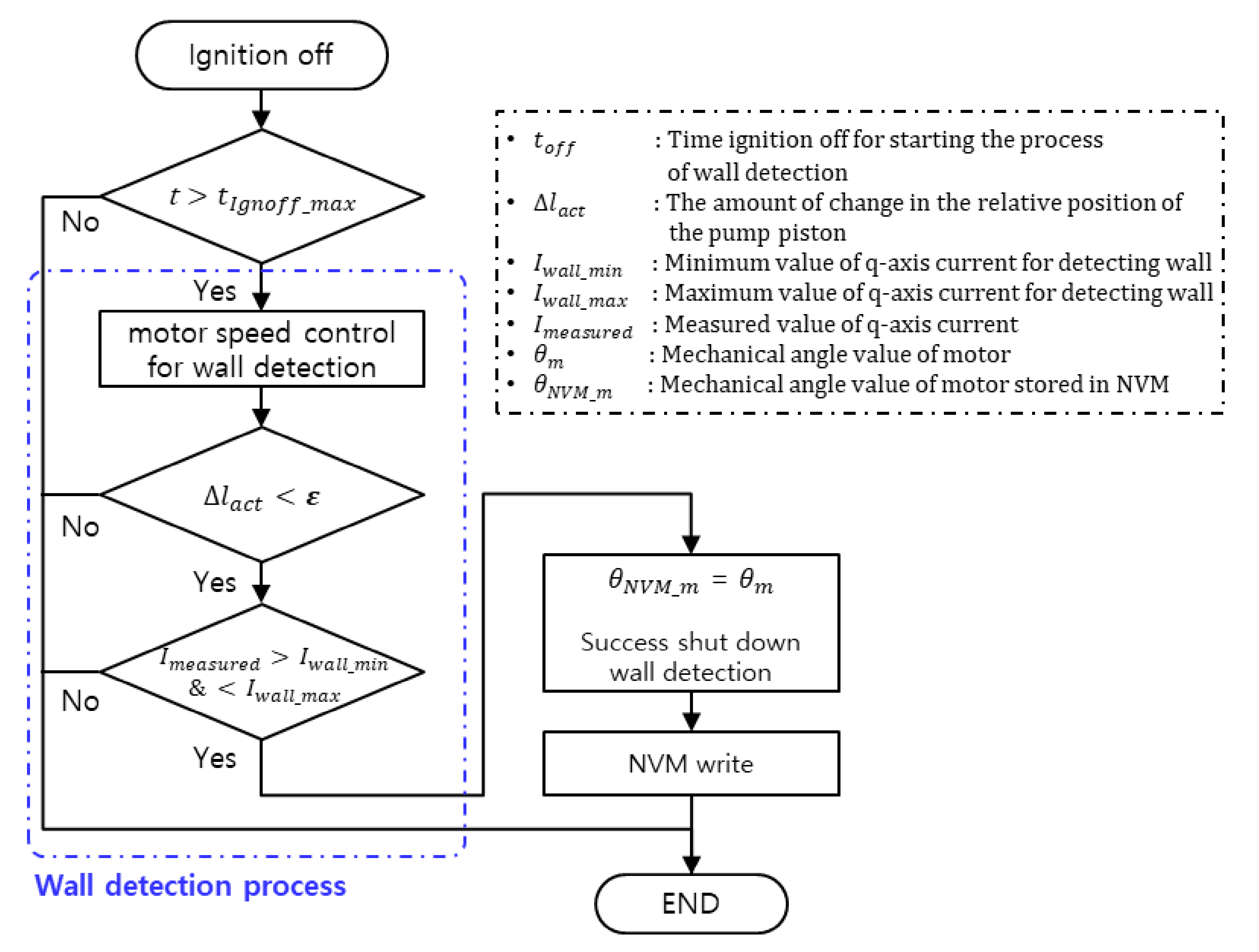
3.2.1. Wall Detection Process with the Ignition off

The proposed method aligns and calculates the pump piston position inside the EHB actuator in real time without a position sensor. As shown in Figure 3a, the process of aligning the pump piston with the back wall is called wall detection. This process should be performed primarily when the vehicle is in the ignition off state. When this ignition off state of the vehicle expires after a valid amount of time, the ECU of the EHB system turns off. Before the ECU is turned off, the wall detection process shown in Figure 4 is performed. The wall detection method proposed above is performed primarily when the vehicle is turned off. When the power of the ECU is turned on, the process shown in Figure 5 is performed.
A detailed description of the flowchart in Figure 4 is as follows:
  • After t o f f has elapsed after ignition off, only the master ECU performs motor speed control for wall detection. When the ignition is on or the driver presses the brake pedal, t is reset.
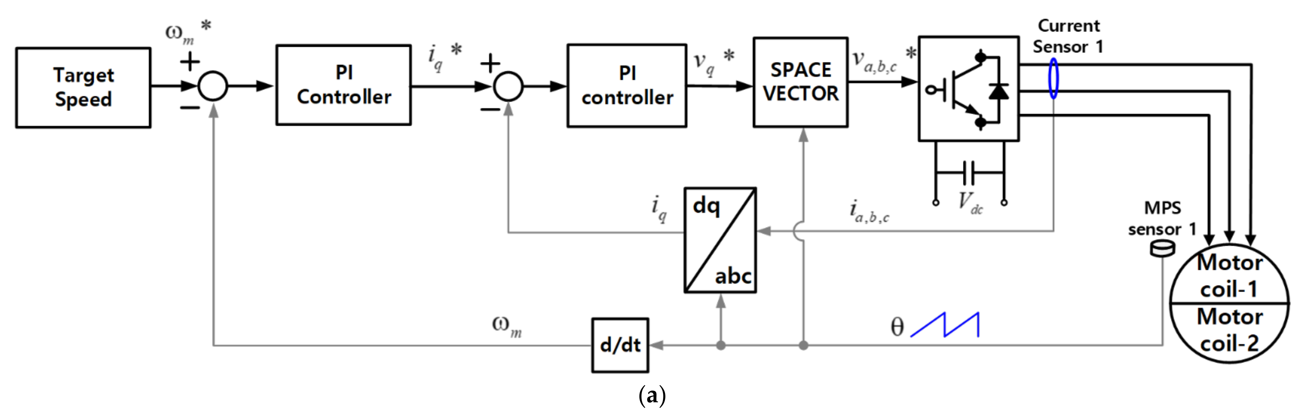
  • As shown in Figure 6a, the motor speed control for wall detection maintains a constant target speed reference. The master ECU executes PI control using the current value measured by the current sensor and speed value of the motor based on the motor position sensor (MPS).
  • While performing motor speed control for wall detection, if Δ l a c t is less than the value of ε when the pump piston touches the rear wall, it is judged that the pump piston inside the actuator is stably in contact with the rear wall.
  • When the pump piston is stably in contact with the rear wall, the value of I m e a s u r e d increases by the I gain of the motor speed control for wall detection. If I m e a s u r e d is between I w a l l _ m i n and I w a l l _ m a x , it is deemed that wall detection is successful.
  • When wall detection is deemed to have been successfully performed, the value of θ m is written as θ n v m _ m in the nonvolatile memory (NVM) circuit in the master ECU, and the corresponding value is maintained even when the ECU is reset.
  • Once Steps 1 to 5 are completed or wall detection remains incomplete, the ECU of the EHB system is turned off.

3.2.2. Motor Initial Operation with the ECU on

By attaching the pump piston position to the rear wall of the actuator through the previous wall detection process, when the ECU is turned on again, the wall detection process can be skipped, thereby reducing the overall time required for the motor initial operation. However, if the motor inside the EHB system rotates while the power is turned off, the processes in the previous wall detection become invalid. Therefore, we propose a method for an initial motor operation to align the pump piston positions. A detailed description of the flowchart for initial motor operation, as shown in Figure 5, is as follows:
  • When the ECU is on, the master ECU checks the success of shutdown of wall detection through the flag stored in the NVM.
  • If it is confirmed that wall detection was successful in the previous state, check whether θ N V M _ m is between θ m _ m i n and θ m _ m a x .
  • If the value of θ N V M _ m is valid, setting of the position reference is performed. The master ECU sets the pump piston position to the rear wall, which allows calculation of the movement distance of the pump piston depending on the angle of rotation of the motor.
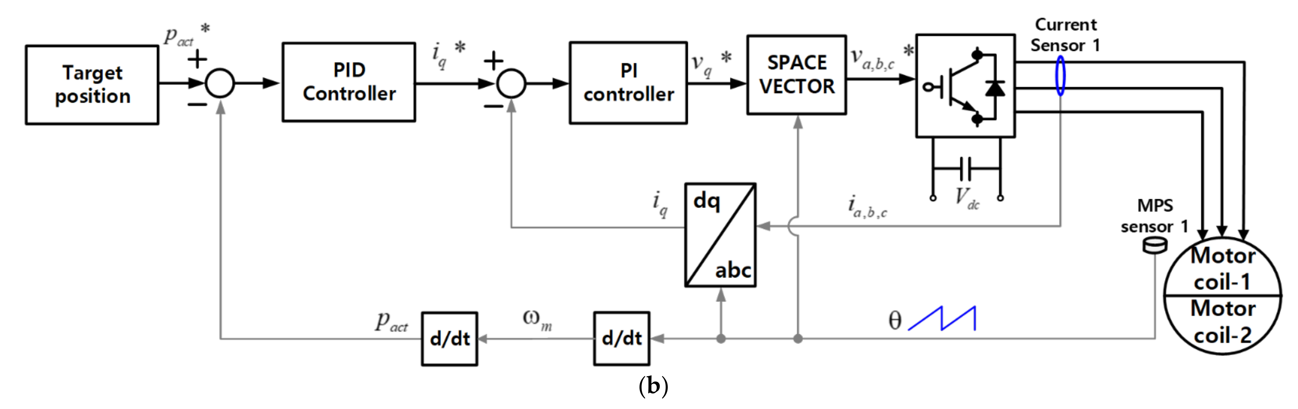
  • Execute motor position control for the set origin. As shown in Figure 6b, the motor position control moves the pump piston to a stable distance from the rear wall. This is to prevent any mechanical deformation caused by the collision of the pump piston with the front and rear walls of the actuator.
  • As the pump piston moves to the reference origin, check whether the value of p a c t is between p o r g _ m i n and p o r g _ m a x . The motor position control process is continued until the pump piston position reaches the target reference origin area.
  • Check whether the measured current value I m e a s u r e d of the DW-PMSM is between I o r g _ m i n and I o r g _ m a x . If the condition is satisfied, it is judged that the motor’s initial operation was performed successfully.
If it is confirmed that wall detection failed in the previous cycle, the wall detection process is performed again. Moreover, if wall detection was not successfully performed, the motor initial operation is judged to have failed. In addition, if it is determined that the value of θ N V M _ m is invalid even after wall detection was successful in the previous cycle, the wall detection process should be performed again. Similarly, if wall detection was not performed successfully in this process, the motor initial operation is judged to have failed. In Steps 4 to 6 above, if the values of the pump piston position p a c t and measured current I m e a s u r e d of the DW-PMSM do not meet the conditions, the motor initial operation is not deemed to be a failure. This is because the absolute position of the pump piston has already been set through the wall detection process. If the driver presses the pedal, the EHB system can control the motor, so Steps 4 to 6 can be skipped.

4. Proposed Control Strategy of DW-PMSM for Generating Target Brake Pressure

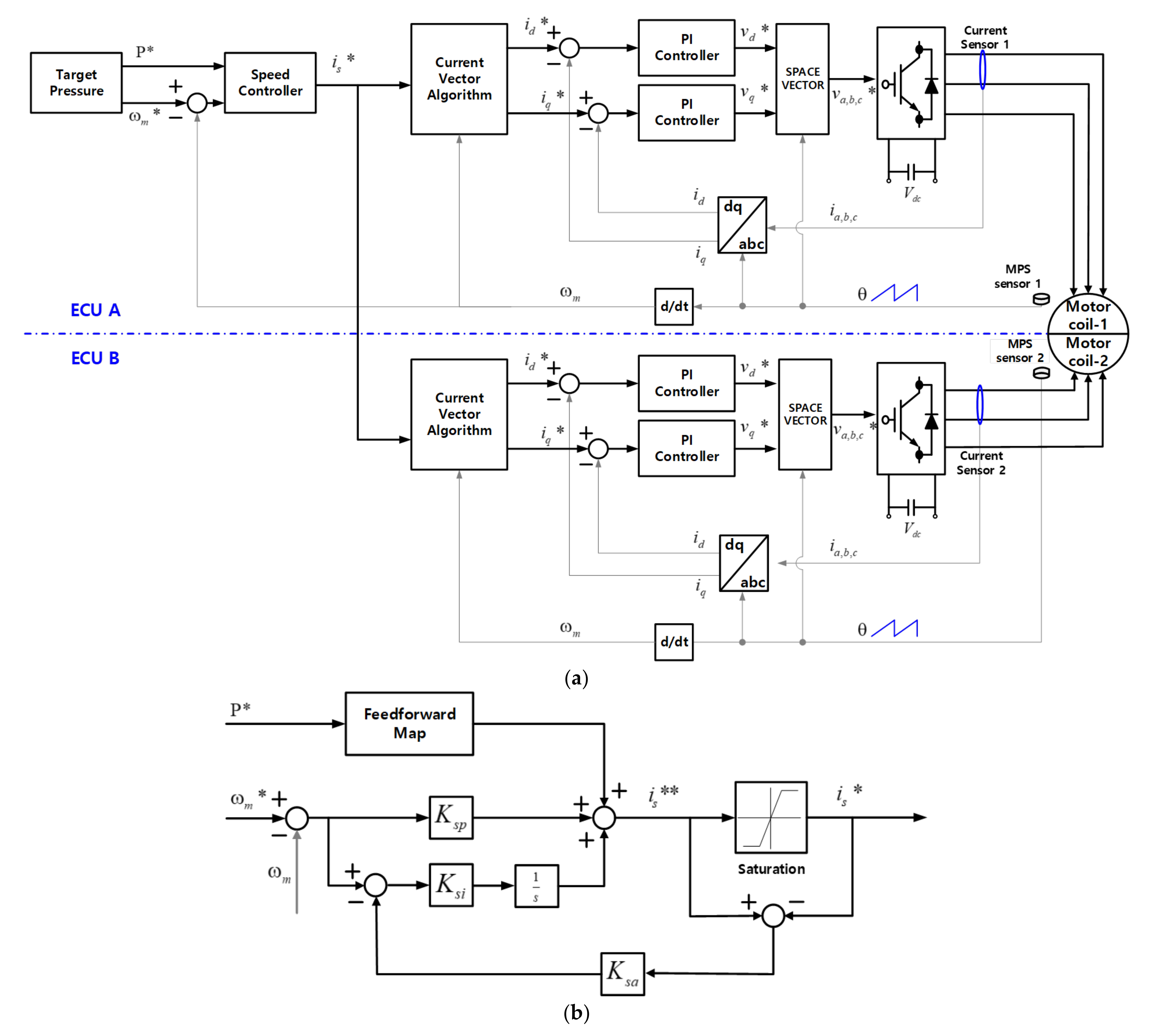
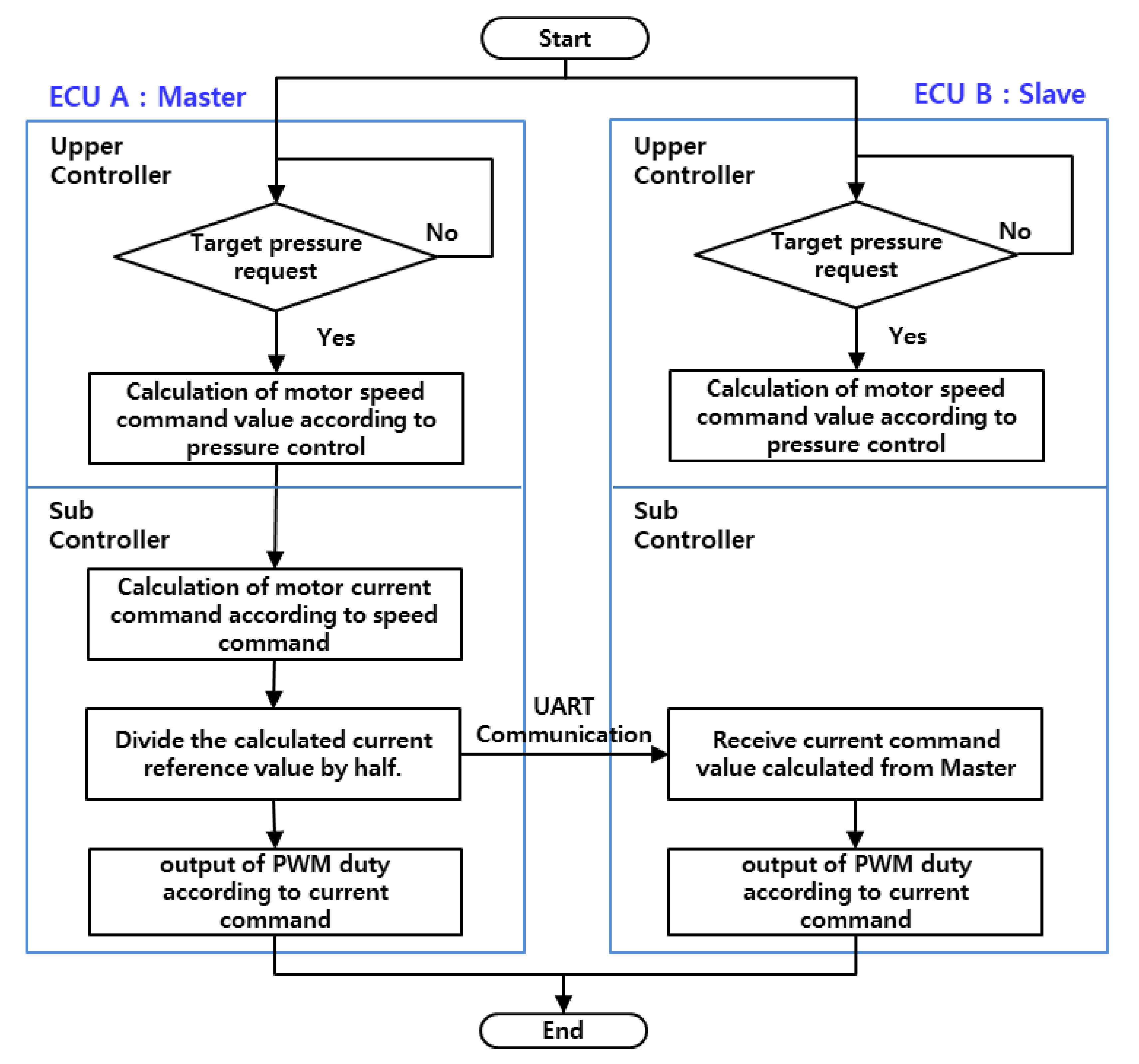
4.1. Current Motor Control Method When the EHB System Is in Normal State

The current control method for the DW-PMSM has been studied extensively for control stability [22,23,24,25,26,27,28]. This paper presents a current control method based on the two-individual-current control method to ensure balanced current in each winding of the DW-PMSM. The two-individual-current control is a useful method in industrial applications because vector control for a single three-phase machine can be used redundantly. Furthermore, it has the advantage of minimizing the instability of the current that can be caused by minute differences in the two sets of three-phase stator windings [25,26]. Figure 7a schematically shows the current motor control methods for the DW-PMSM of the EHB system. As shown in Figure 2a, each ECU is composed of current and MPS sensors.
Once the required brake pressure is calculated by the upper controller of each ECU, different brake command values may appear. To solve this problem, as shown in Figure 8, we propose a method to use the upper controller value in the master ECU in the normal state. When the driver presses the brake pedal, the upper controller outputs the speed command value of the DW-PMSM to output the target brake pressure. The sub-controller of the master ECU then calculates the motor current command value according to the speed command value. Figure 7b schematically shows the process for this part. In this work, the feedforward current reference value is already calculated, as previously described in Section 2. The extracted feedforward current reference in Figure 2d is used as the feedforward map of the master ECU speed controller. The sub-controller generates the current reference value by adding the extracted feedforward value and output of the PI controller through the measured motor speed ( ω m ) . The proposed speed controller generates a current command value ( i s * ) through the anti-windup process using the sum of the feedforward current reference and the feedback current reference ( i s * * ) . The master ECU divides the current reference value into two so that each ECU can generate 50% output. Therefore, the master ECU outputs half of the current command value as PWM duty through the current control. In addition, the slave ECU receives the current command value from the master through UART communication and generates 50% of the torque output from each ECU. Functions are performed in the functional block of ECU B in the lower part of Figure 7a. ECUs A and B are configured by the same current control method, so coil-1 and coil-2 of the DW-PMSM can acquire symmetrical current waveforms through the same pressure reference and control method.

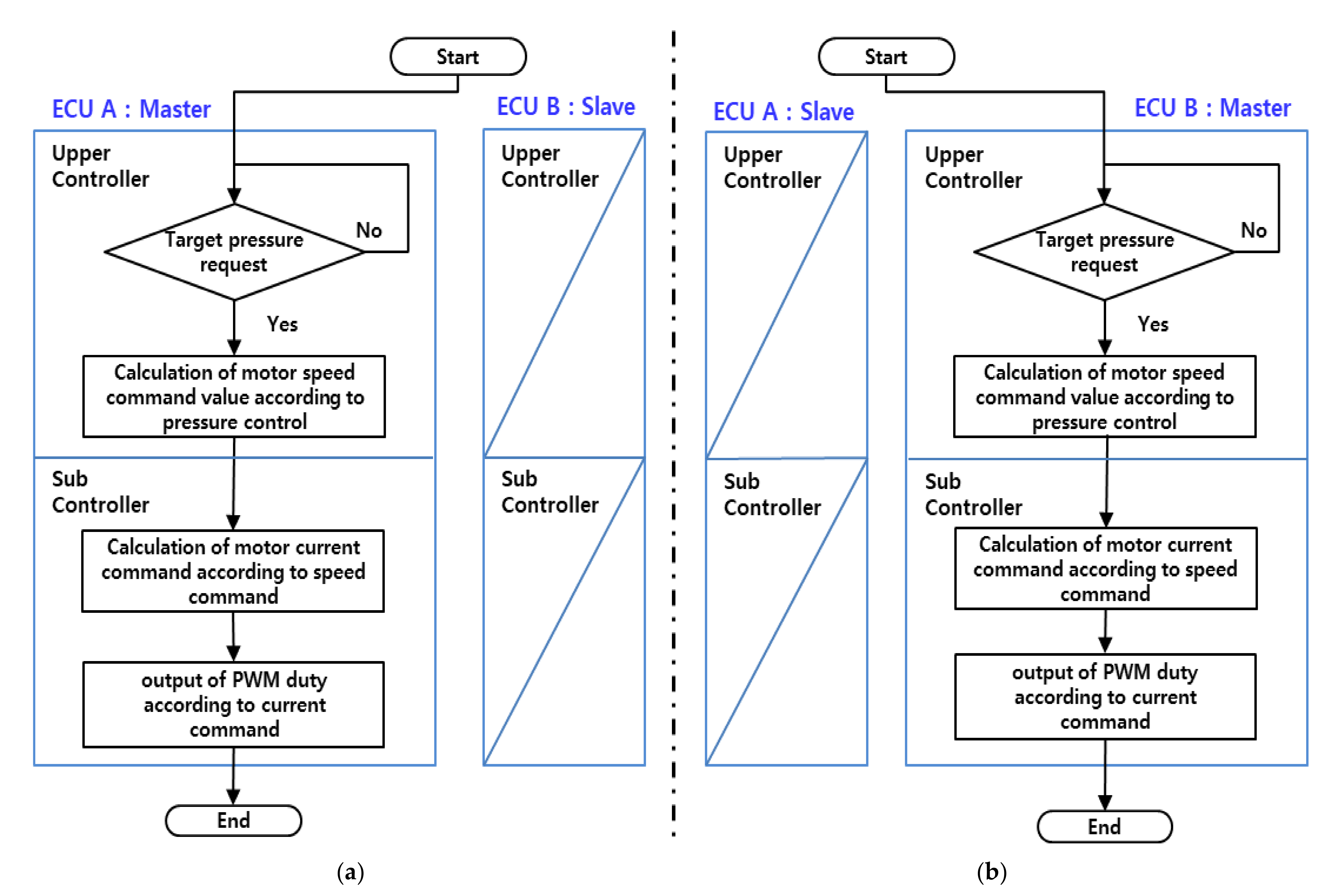
4.2. Current Motor Control Methods When the EHB System Is in A Single Fault State

The EHB system consists of two ECUs, and if one of them is in the fault state, the diagnostic function of the ECU in the normal state identifies this faulty ECU status. It is the same with DW-PMSM, where a fault changes the electrical characteristics of the faulty device. In cases like this, some of the signal changes are discrete and irregular during fault detection [27,28]. If one ECU fails, the remaining ECUs maintain the output so that 50% of the maximum pressure can be output in the normal state. The EHB system is capable of sudden vehicle braking at 50% of the required output. In Figure 9a, if ECU B in the slave state is out of control, the upper controller and sub-controller are executed in ECU A in the master state. Control is performed in the ECU in the master state without transmitting the current command value to the slave through UART communication. In Figure 9b, if ECU A, which is in the master state, is out of control, then ECU B, which is in the slave state, is converted to the master. The configuration is such that only the master ECU can use the output value of the upper controller, so ECU B can continuously control the target pressure and speed command values of the DW-PMSM that are normally controlled by ECU A.
Through this process, the EHB system composed of two ECUs can maintain safe braking performance under all conditions except for the double fault condition. In this study, when a failure occurs in the counterpart ECU when brake pressure is applied, it was experimentally proven that the brake pressure can be maintained constant before and after failure.

5. Experimental Verification

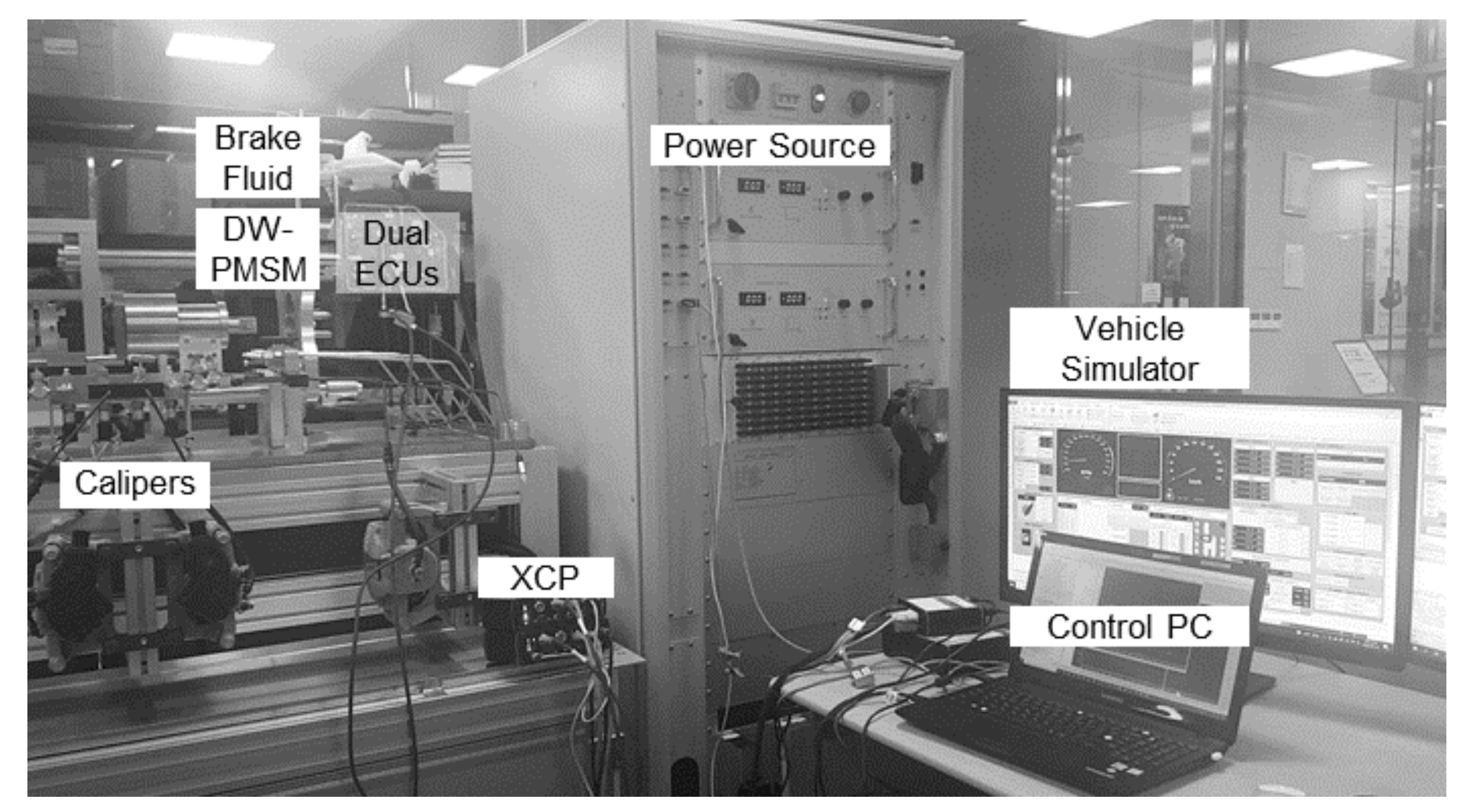
5.1. Test Equipment Setup and DW-PMSM Parameters

The DW-PMSM used in this work consists of 8 poles and 12 slots. The maximum value for the phase current of each motor coil is 60 A. The parameters of the DW-PMSM are shown in Table 1. The EHB system contains the dual ECUs, actuators, valves, and sensors (MPS, current sensing) described earlier. The two ECUs are electrically isolated and powered by one battery each. The EHB system and four-brake caliper are shown in Figure 10. When the motor rotates, brake pressure is created in the HCU, which increases the hydraulic pressures in the four calipers. The test bench consisted of two power supplies, the EHB system, a control PC, and a simulator, as shown in Figure 10. In addition, the universal measurement and calibration protocol (XCP) equipment was linked with the control PC to measure data in real time. The ignition on/off settings and driving states were set through the vehicle simulator.

5.2. Test Results of Proposed Motor Operation Method for Position Alignment of Actuator

In Section 3, we discussed how the proposed pump piston alignment method enables the calculation of the pump piston position inside the EHB actuator in real time without a position sensor. To prove the proposed method, a verification was carried out through a test bench. The wall detection process with the ignition off is presented in Figure 11. While performing motor speed control for wall detection, if Δ l a c t is less than the value of ε when the pump piston touches the rear wall, as shown in Figure 11, it is judged that the pump piston inside the actuator is stably in contact with the rear wall. Moreover, the value of ( I q 1 ) increases by the I gain of the motor speed control for wall detection. Hence, when the measured current value ( I q 1 ) is between the minimum current reference I w a l l _ m i n and maximum current reference I w a l l _ m a x , it is deemed that the wall detection process was successfully conducted. Hence, the absolute pump piston position is set at −1.5 mm. Lastly, the mechanical angle value of the motor ( θ m ) and related information is written in the NVM circuit in the master ECU to skip the wall detection process when the ECU power is applied again.
When the ECU is turned on again, the wall detection process can be skipped. First of all, the master ECU judges the success of the shutdown of wall detection through the flag stored in the NVM when the ECU is on. Moreover, if the value of the mechanical angle stored in the NVM ( θ N V M ) does not differ from the current mechanical angle within the 8deg, it is determined that the pump piston is already located on the rear wall. The measurement graphs of the current and position, as shown in Figure 11, show the process of motor position control for the origin set. from −1.5 mm to 0 mm of the pump piston position with the ECU on.
However, if the previous wall detection process failed or the ECU was abnormally initialized, the wall detection process and motor position control for the origin set. should be conducted together as shown Figure 12. The initial position of the pump piston is shown as 1.2 mm, which is an example of an error that appears when calculating the position by integrating the mechanical angle of the motor. After finishing the wall detection process, the absolute pump piston position is set to −1.5 mm. Then, the process of motor position control is conducted to move to the pump piston position from −1.5 mm to 0 mm. The target position command is created when performing motor position control for the origin set., and the current command, which is the output value of position control, moves the pump piston to the origin (0 mm). Hence, the target position command is not generated when wall detection and brake pressure control are performed.

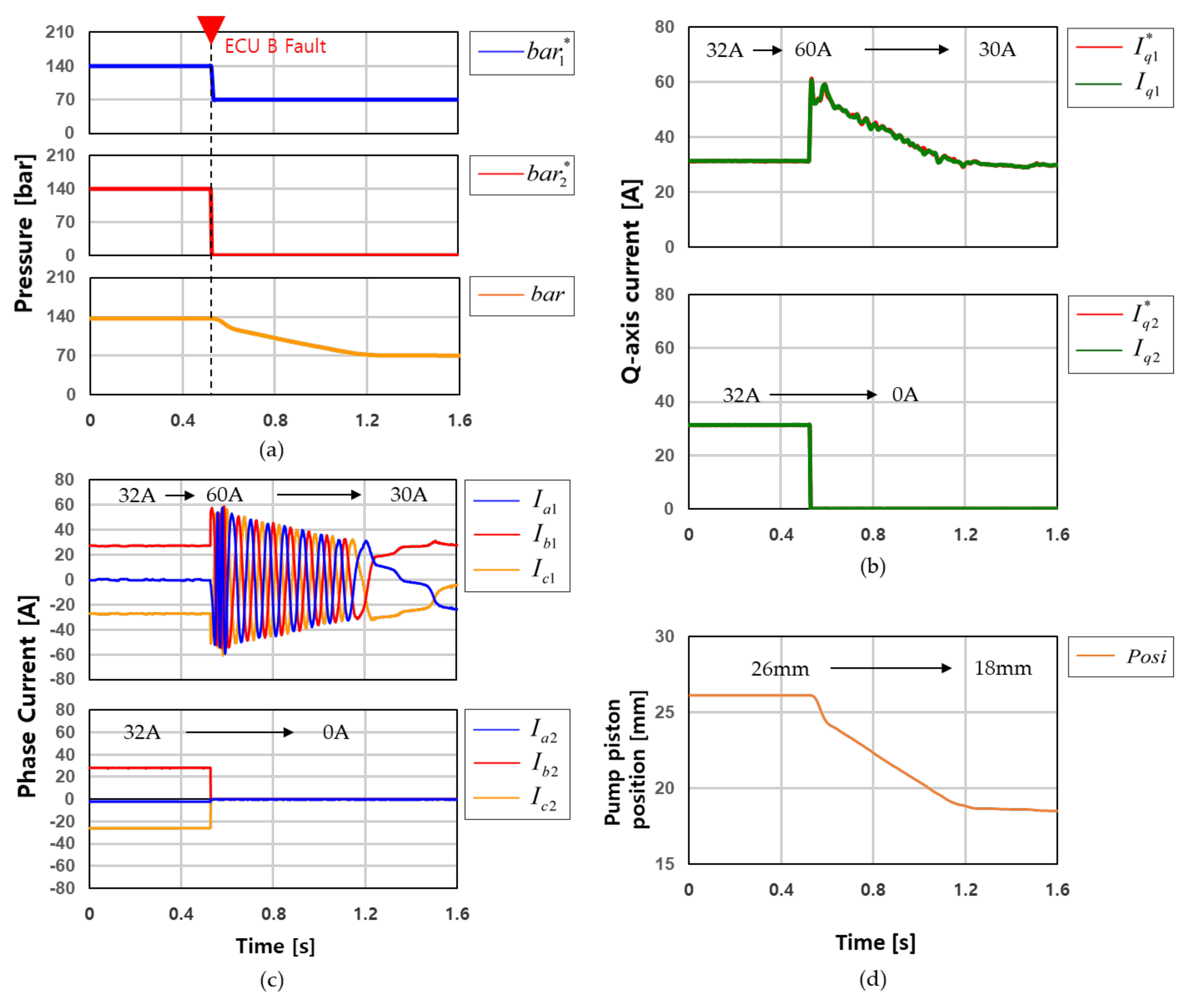
5.3. Test Results for Proposed Control Strategy of DW-PMSM for Generating Target Brake Pressure

In Section 4, we discussed how if one ECU fails, the remaining ECUs should maintain the output so that 50% of the maximum pressure can be output in the normal state. In order to prove the control strategy proposed in this work, a verification was carried out through the explained test bench. First of all, if ECU B fails while the EHB system maintains a brake pressure of 140 bar, depending on the vehicle condition, all functions of ECU B are stopped, as shown in Figure 13. The ECU B failed at about 0.5 s. All functions of ECU B were inhibited, and the target pressure ( b a r 2 * ) and output current command ( I q 2 * ) of ECU B were instantaneously switched to zero. ECU A detected the status of ECU B and performed control to stably reduce the brake pressure to 70 bar. Accordingly, the vehicle could continuously operate the brake function. Moreover, the maximum current that each ECU could output was 60 A. It is also possible to set the brake pressure higher than that shown in Figure 13 within the maximum allowable current in ECU A.
When ECU A fails while the EHB system maintains a brake pressure of 140 bar, depending on the vehicle condition, all functions of ECU A are stopped, as shown in Figure 14. ECU A failed at about 0.5 s. All functions of ECU A were inhibited, and the target pressure b a r 1 * and output current command I q 1 * of ECU A were instantaneously switched to zero. ECU B detected the status of ECU A and performed control to stably reduce the brake pressure to 70 bar.
When ECU A, which is in the master state, is out of control, then ECU B, which is in the slave state, is converted to the master. As presented in Section 4.2, only the master ECU can use the output value of the upper controller, and the output current command ( I q 2 * ) of ECU B is momentarily output to zero, as shown in Figure 14b. However, this did not affect pressure performance because it occurred within 1 ms.
As a result, we demonstrated that the proposed control method can be maintained at a constant brake pressure even if any ECU fails. The measurement graphs of the brake pressure, motor current, and pump piston position in Figure 13 and Figure 14 show the equal control with a time interval of 800 ms.

6. Conclusions

In this study, the redundancy motor control method for an EHB system composed of a DW-PMSM demonstrated continuous brake performance to stably stop the vehicle even if a failure occurs in one of the ECUs. It was also proven that the brake pressure performance can be maintained constant even when one ECU fails, and we verified the maintenance of high brake pressure in the normal state. Hence, the validity of the brake performance of the redundant EHB system was verified. A particular contribution of this study is that the method can meet the safety standards required by self-driving vehicles, including those for highly automated driving, which reflect the highest standard of automotive safety integrity levels (ASILs) during the entire lifecycle of a safety-critical system.
A proposed initial motor operation method for aligning the pump piston position for wall detection and the origin set. process was proposed and verified in order to not need to mount a position sensor. The test results showed that the position of the pump piston can be continuously identified and used to detect whether the EHB system is operating normally. Hence, the ECU can prevent the pump piston from colliding with the actuator’s wall during brake control. With the presented redundant motor control strategies, this study demonstrated the actual pressure performance when preventing control inhibition in the redundant EHB system.

Author Contributions

The first author is T.J. Other authors contributed as follows: conceptualization, T.J. and K.J.; methodology, T.J.; software, T.J.; validation, T.J., K.J. and J.L.; formal analysis, T.J.; investigation, T.J.; resources, K.J.; writing—original draft preparation, T.J.; writing—review and editing, K.J. and J.L; visualization, T.J.; supervision, J.L. All authors have read and agreed to the published version of the manuscript.

Funding

This research is supported by the Mando Corporation.

Institutional Review Board Statement

Not applicable.

Informed Consent Statement

Not applicable.

Data Availability Statement

The data presented in this study are available upon request from the corresponding author and Mando Corporation. The data are not publicly available as the data also form part of an ongoing study.

Acknowledgments

The authors thank the Mando Corporation for their support with the experimental equipment and advice on the technical design.

Conflicts of Interest

The authors declare no conflict of interest.

References

  1. ISO-26262; Road Vehicles—Functional Safety, 12-2018. ISO: Geneva, Switzerland, 2018.
  2. Leu, K.L.; Huang, H.; Chen, Y.Y.; Huang, L.R.; Ji, K.M. An intelligent brake-by-wire system design and analysis in accord-ance with ISO-26262 functional safety standard. In Proceedings of the 2015 International Conference on Connected Vehicles and Expo (ICCVE), Shenzen, China, 19–23 October 2015; pp. 150–156. [Google Scholar] [CrossRef]
  3. Wang, X.; Wu, X.; Cheng, S.; Shi, J.; Ping, X. Design and Experiment of Control Architecture and Adaptive Dual-Loop Controller for Brake-by-Wire System With an Electric Booster. IEEE Trans. Transp. Electrif. 2020, 6, 1236–1252. [Google Scholar] [CrossRef]
  4. Yong, J.; Gao, F.; Ding, N.; He, Y. Design and validation of an electro-hydraulic brake system using hardware-in-the-loop real-time simulation. Int. J. Autom. Technol. 2017, 18, 603–612. [Google Scholar] [CrossRef]
  5. Wu, J.; Zhang, H.; He, R.; Chen, P.; Chen, H. A mechatronic brake booster for electric vehicles: Design, control, and experi-ment. IEEE Trans. Veh. Technol. 2020, 69, 7040–7053. [Google Scholar] [CrossRef]
  6. Bogdevičius, M.; Prentkovskis, O. Engineering solutions of traffic safety problems of road transport. Transport 2004, 19, 43–50. [Google Scholar] [CrossRef] [Green Version]
  7. Zhao, J.; Song, D.; Zhu, B.; Chen, Z.; Sun, Y. Nonlinear backstepping control of electro-hydraulic brake system based on bond graph model. IEEE Access 2020, 8, 19100–19112. [Google Scholar] [CrossRef]
  8. Yang, Y.; Tang, Q.; Bolin, L.; Fu, C. Dynamic Coordinated Control for Regenerative Braking System and Anti-Lock Braking System for Electrified Vehicles Under Emergency Braking Conditions. IEEE Access 2020, 8, 172664–172677. [Google Scholar] [CrossRef]
  9. Tavernini, D.; Vacca, F.; Metzler, M.; Savitski, D.; Ivanov, V.; Gruber, P.; Hartavi, A.E.; Dhaens, M.; Sorniotti, A. An explicit nonlinear model predictive ABS controller for electro-hydraulic braking systems. IEEE Trans. Ind. Electron. 2020, 67, 3990–4001. [Google Scholar] [CrossRef]
  10. Savitski, D.; Ivanov, V.; Schleinin, D.; Augsburg, K.; Pütz, T.; Lee, C.F. Advanced control functions of decoupled elec-tro-hydraulic brake system. In Proceedings of the 2016 IEEE 14th International Workshop on Advanced Motion Control (AMC), Auckland, New Zealand, 22–24 April 2016; pp. 310–317. [Google Scholar] [CrossRef]
  11. D’alfio, N.; Morgando, A.; Sorniotti, A. Electro-hydraulic brake systems: Design and test through hardware-in-the-loop simulation. Veh. Syst. Dyn. 2006, 44 (Suppl. S1), 378–392. [Google Scholar] [CrossRef]
  12. Lin, F.; Hung, Y.; Tsai, M. Fault-tolerant control for six-phase PMSM drive system via intelligent complementary slid-ing-mode control using TSKFNN-AMF. IEEE Trans. Ind. Electron. 2013, 60, 5747–5762. [Google Scholar] [CrossRef]
  13. Cao, R.; Cheng, M.; Hua, W. Investigation and general design principle of a new series of complementary and modular linear FSPM motors. IEEE Trans. Ind. Electron. 2013, 60, 5436–5446. [Google Scholar] [CrossRef]
  14. Jiang, X.; Huang, W.; Cao, R.; Hao, Z.; Jiang, W. Electric drive system of dual-winding fault-tolerant permanent-magnet motor for aerospace applications. IEEE Trans. Ind. Electron. 2015, 62, 7322–7330. [Google Scholar] [CrossRef]
  15. Chen, X.; Wang, J.; Patel, V.I. A generic approach to reduction of magnetomotive force harmonics in permanent-magnet machines with concentrated multiple three-phase windings. IEEE Trans. Magn. 2014, 50, 1–4. [Google Scholar] [CrossRef]
  16. Wang, S.; Zhu, Z.; Pride, A.; Shi, J.; Deodhar, R.; Umemura, C. Comparison of different winding configurations for dual three-phase interior PM machines in electric vehicles. World Electr. Veh. J. 2022, 13, 51. [Google Scholar] [CrossRef]
  17. Barcaro, M.; Bianchi, N.; Magnussen, F. Faulty operations of a PM fractional-slot machine with a dual three-phase winding. IEEE Trans. Ind. Electron. 2011, 58, 3825–3832. [Google Scholar] [CrossRef]
  18. Abdel-Khalik, A.S.; Ahmed, S.; Massoud, A.M. Effect of multilayer windings with different stator winding connections on interior PM machines for EV applications. IEEE Trans. Magn. 2016, 52, 1–7. [Google Scholar] [CrossRef]
  19. Xu, P.; Feng, J.H.; Guo, S.Y.; Feng, S.; Chu, W.; Ren, Y.; Zhu, Z.Q. Analysis of dual three-phase permanent-magnet synchronous machines with different angle displacements. IEEE Trans. Ind. Electron. 2018, 65, 1941–1954. [Google Scholar] [CrossRef]
  20. Barcaro, M.; Bianchi, N.; Magnussen, F. Analysis and tests of a dual three-phase 12-slot 10-pole permanent-magnet motor. IEEE Trans. Ind. Appl. 2010, 46, 2355–2362. [Google Scholar] [CrossRef]
  21. Zhongxun, W.; Zhonghua, D. The research of LVDT nonlinearity data compensation based on RBF neural network. In Proceedings of the 2008 7th World Congress on Intelligent Control and Automation, Chongqing, China, 25–27 June 2008; pp. 4591–4594. [Google Scholar] [CrossRef]
  22. Gunasekaran, V.; George, B.; Aniruddhan, S.; Janardhanan, D.D.; Palur, R.V. Performance analysis of oscillator-based read-out circuit for LVDT. IEEE Trans. Instrum. Meas. 2019, 68, 1080–1088. [Google Scholar] [CrossRef]
  23. Krause, P.C.; Wasynczuk, O.; Sudhoff, S.D.; Pekarek, S.D. Pekarek Analysis of Electric Machinery and Drive Systems; John Wiley and Sons: Hoboken, NJ, USA, 2013; p. 680. [Google Scholar]
  24. Demir, Y.; Aydin, M. A novel dual three-phase permanent magnet synchronous motor with asymmetric stator winding. IEEE Trans. Magn. 2016, 52, 1–5. [Google Scholar] [CrossRef]
  25. Singh, G.K.; Nam, K.; Lim, S.K. A simple indirect field-oriented control scheme for multiphase induction machine. IEEE Trans. Ind. Electron. 2005, 52, 1177–1184. [Google Scholar] [CrossRef]
  26. Hu, Y.; Zhu, Z.Q.; Odavic, M. Comparison of two-individual current control and vector space decomposition control for dual three-phase PMSM. IEEE Trans. Ind. Appl. 2017, 53, 4483–4492. [Google Scholar] [CrossRef]
  27. Yin, S.; Xiao, B.; Ding, S.X.; Zhou, D. A review on recent development of spacecraft attitude fault tolerant control system. IEEE Trans. Ind. Electron. 2016, 63, 3311–3320. [Google Scholar] [CrossRef]
  28. Yang, C.; Peng, T.; Yang, X.; Gui, W. A fault-injection strategy for traction drive control systems. IEEE Trans. Ind. Electron. 2017, 64, 5719–5727. [Google Scholar] [CrossRef]
Figure 1. Configuration of the redundant electro-hydraulic brake system: (a) flowchart of the brake operation and (b) schematics of the dual ECUs and DW-PMSM.
Energies 15 05090 g001aEnergies 15 05090 g001b
Figure 2. According to the applied current reference: (a) changes in the current of motor coil-1; (b) changes in the current of motor coil-2; (c) generated pressure according to the current of motor coil-1 and coil-2; (d) extracted feedforward current reference of the DW-PMSM for generating pressure.
Energies 15 05090 g002
Figure 3. Pump piston movement in the actuator according to motor driving: (a) initial actuator configuration of the EHB system; (b) brake pressure application with pump piston advancement; (c) brake pressure release with retraction of the pump piston.
Energies 15 05090 g003
Figure 4. Flowchart of the proposed wall detection with the EHB system with the ignition off.
Energies 15 05090 g004
Figure 5. Flowchart of the proposed motor initial operation with the EHB system ECU on.
Energies 15 05090 g005
Figure 6. Proposed motor operation control method for aligning the pump piston: (a) functional block diagram for speed control of the wall detection process; (b) functional block diagram for position control of origin setting.
Energies 15 05090 g006aEnergies 15 05090 g006b
Figure 7. Proposed motor current control method for generating brake pressure: (a) functional block diagram for current control of the DW-PMSM; (b) functional block diagram for the proposed speed controller.
Energies 15 05090 g007
Figure 8. Flowchart of the proposed current control method in the normal state.
Energies 15 05090 g008
Figure 9. Flowchart of the proposed current control method in the normal state: (a) single fault in ECU B; (b) single fault in ECU A.
Energies 15 05090 g009
Figure 10. Photo of test bench.
Energies 15 05090 g010
Figure 11. Measurement results regarding wall detection process with the ignition off and wall detection skip and origin set. process through motor initial operation with the ECU on: (a) q−axis current command value ( I q 1 * ) and measured q−axis current value ( I q 1 ) ; (b) target pump piston position and calculated pump piston position.
Energies 15 05090 g011
Figure 12. Measurement results regarding wall detection and origin set. process with the ECU on: (a) q−axis current command value ( I q 1 * ) and measured q−axis current value ( I q 1 ) ; (b) target pump piston position and calculated pump piston position.
Energies 15 05090 g012
Figure 13. Measurement results when the malfunctioning of ECU B occurs: (a) target pressure ( b a r 1 * , b a r 2 * ) and measured pressure (bar); (b) q−axis current command value ( I q 1 * , I q 2 * ) and measured q−axis current value ( I q 1 ,   I q 2 ); (c) measured three-phase current ( I a 1 ,   I b 1 ,   I c 1 ) ,   I a 2 ,   I b 2 ,   I c 2 ; (d) calculated pump piston position.
Energies 15 05090 g013
Figure 14. Measurement results when the malfunctioning of ECU A occurs: (a) target pressure ( b a r 1 * , b a r 2 * ) and measured pressure (bar); (b) q−axis current command value ( I q 1 * , I q 2 * ) and measured q−axis current value ( I q 1 ,   I q 2 ); (c) measured three-phase current ( I a 1 ,   I b 1 ,   I c 1 ) ,   I a 2 ,   I b 2 ,   I c 2 ; (d) calculated pump piston position.
Energies 15 05090 g014
Table 1. The design parameters of the DW-PMSM.
Parameter NameValue
Resistance ( Ω )0.023
d-axis self-inductance (mH)0.078
q-axis self-inductance (mH)0.079
Flux linkage (Wb)0.0055
DC link voltage (V)13
Publisher’s Note: MDPI stays neutral with regard to jurisdictional claims in published maps and institutional affiliations.

