Review

Novel Trends in Proton Exchange Membrane Fuel Cells

by
Abdul Ghani Olabi
1,2,3,*,
Tabbi Wilberforce
3,*,
Abdulrahman Alanazi
4,
Parag Vichare
4,
Enas Taha Sayed
5,6,
Hussein M. Maghrabie
7,
Khaled Elsaid
8 and
Mohammad Ali Abdelkareem
1,2,5,6,*
1
Department of Sustainable and Renewable Energy Engineering, University of Sharjah, Sharjah P.O. Box 27272, United Arab Emirates
2
Sustainable Energy & Power Systems Research Centre, RISE, University of Sharjah, Sharjah P.O. Box 27272, United Arab Emirates
3
Mechanical Engineering and Design, School of Engineering and Applied Science, Aston University, Aston Triangle, Birmingham B4 7ET, UK
4
Institute of Engineering and Energy Technologies, The University of the West of Scotland, Paisley PA1 2BE, UK
5
Centre for Advanced Materials Research, University of Sharjah, Sharjah P.O. Box 27272, United Arab Emirates
6
Chemical Engineering Department, Faculty of Engineering, Minia University, Elminia 61519, Egypt
7
Department of Mechanical Engineering, Faculty of Engineering, South Valley University, Qena 83521, Egypt
8
Chemical Engineering Program, Texas A & M University at Qatar, Doha 23874, Qatar
*
Authors to whom correspondence should be addressed.
Energies 2022, 15(14), 4949; https://doi.org/10.3390/en15144949
Submission received: 11 May 2022 / Revised: 13 June 2022 / Accepted: 22 June 2022 / Published: 6 July 2022
(This article belongs to the Collection Renewable Energy and Energy Storage Systems)

Abstract

:
Fuel cells (FCs) have received huge attention for development from lab and pilot scales to full commercial scale. This is mainly due to their inherent advantage of direct conversion of chemical energy to electrical energy as a high-quality energy supply and, hence, higher conversion efficiency. Additionally, FCs have been produced at a wide range of capacities with high flexibility due to modularity characteristics. Using the right materials and efficient manufacturing processes is directly proportional to the total production cost. This work explored the different components of proton exchange membrane fuel cells (PEMFCs) and their manufacturing processes. The challenges associated with these manufacturing processes were critically analyzed, and possible mitigation strategies were proposed. The PEMFC is a relatively new and developing technology so there is a need for a thorough analysis to comprehend the current state of fuel cell operational characteristics and discover new areas for development. It is hoped that the view discussed in this paper will be a means for improved fuel cell development.

1. Introduction

Securing freshwater and sustainable energy resources while saving the environment are top priorities for human beings. Renewable energy sources are sustainable with low or no environmental impacts [1,2]. Developing eco-friendly, efficient energy conversion devices is a basic requirement for the efficient use of renewable energy sources. Fuel cells are electrochemical devices that have high energy conversion efficiency, are environmentally friendly, and have demonstrated promising results using different renewable energy resources such as biomass [3,4]. Furthermore, fuel cells can be used as biosensors [5,6,7] and can be applied for simultaneous wastewater treatment and electricity generation such as in the case of microbial fuel cells [8,9,10,11] and direct urea fuel cells [12,13]. The fuel cell (FC) is an electrochemical device that transforms chemical energy in fuel directly to electricity with water, in the case of hydrogen being the fuel, and heat as by-products. Hydrogen is considered as the future fuel as it has no environmental impacts (green hydrogen) and it could be produced from water by electrolysis and various other methods [14,15,16]. A low-temperature proton exchange membrane fuel cell (PEMFC) is the most common type of FC and is projected as the future of the energy generation industry; hence, it is a possible replacement for fossil-based technologies [17,18]. The conversion efficiencies for these types of FCs are much higher compared to conventional energy conversion devices [19]. Additionally, there is no noise, due to the absence of moving parts, and no harmful emissions as well. These merits project the futuristic prospects of these energy conversion devices.
FC performance is subject to ambient conditions such as cell operating current and temperature. Other factors such as the characteristics of the materials used, humidity, and pressure all affect the overall performance of the cell. Consequently, to achieve an optimized performance, this multi-variable-dependent behavior needs to be precisely chosen [20]. In addition, during operation, the cell voltage is subject to electric losses and, thus, varies with the electric load. The type of material used in making the membrane PEMFC can also increase or reduce the cell resistance, hence reducing the entire performance of the cell. Other losses such as mass transfer losses also reduce the FC performance. The different types of losses encountered in FCs are shown in Figure 1 and can be summarized as:
-
Activation losses: These indicate that PEMFC requires specific energy to cause excitation of the electrons via the external circuit, which depends mainly on the catalyst material, loading, and utilization, and are predominant at low currents [17].
-
Ohmic losses: These occur due to the flow of electrons or protons and depend on the material of the membrane electrode assembly (MEA), more specifically the membrane conductivity and thickness. This region is a desirable operating zone as the maximum output power of the PEMFC exists here.
-
Mass transfer losses: These are due to the rate of consumption of the reactant in the electrochemical reaction and are characterized by a high voltage drop at high currents [21]. These losses depend on the porosity of the gas diffusion layer (GDL) as well as the hydrophobicity characteristics of the membrane and GDL.
Despite the many advantages of PEMFCs, their commercialization is subject to their competition with conventional combustion engines. There has been accelerated progress in the development of FCs that are cheap but durable in the last few decades. Presently, PEMFCs face several issues before they can successfully substitute for conventional power systems, as reviewed extensively by Wee [22] and Chandan et al. [23]. The potential of introducing this technology mainly depends on the availability of hydrogen supplies and the cost per kW of the FC system. Several studies have presented new paths for hydrogen supply, and the cost is still substantial [24,25]. Additionally, the manufacturers have to reduce manufacturing costs and, hence, reduce the price per kW to make this market profitable and available to more consumers. This review, therefore, sought to explore and critically discuss the current and state-of-the-art materials used for PEMFCs as well as their properties along with the various fabrication techniques for manufacturing FC components.

2. Components of Fuel Cells/Stacks

An FC stack consists of many individual cells that are organized in a way such that there is an electrical contact between the anode and the cathode of one cell to the other. The configuration of these cells ensures that the same current is passed throughout the stack. The desired voltage of application is often determining the number of cells per stack. Different active areas ranging from 300 to 1000 cm2 have all been experimented with. The active area of the FC is also directly proportional to the power output required. Increasing areas affects the uniformity of flow distribution and makes it hard to achieve throughout the cells. Increasing the number of cells, on the other hand, is limited by the stack clamping force and structural rigidity [26]. Additionally, the weight as well as the volume of the stack also revolve around the active area and contribute to determining the power density of the stack [27]. 
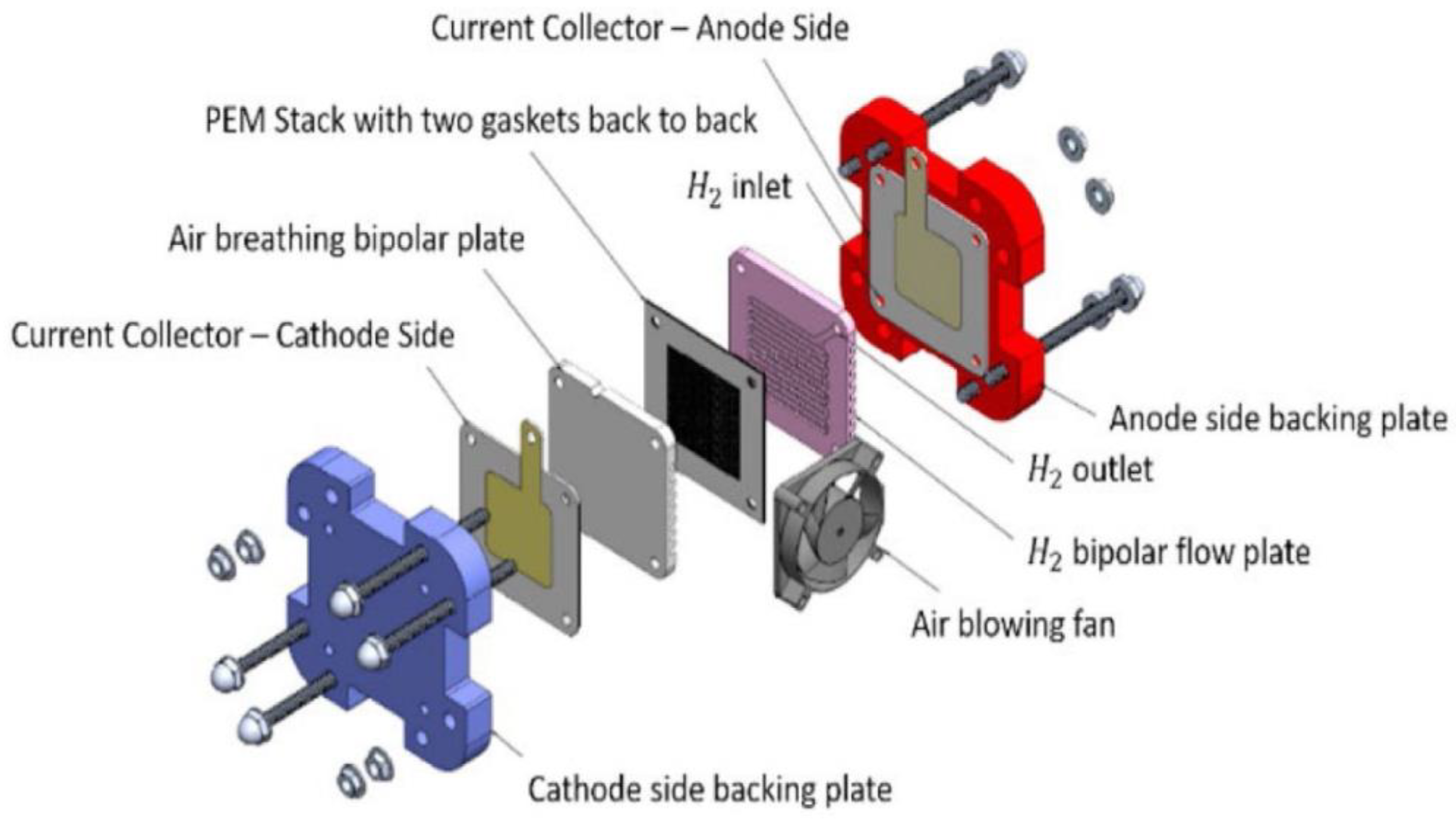
Figure 2 captures the key components of FCs, namely, the membrane electrode assembly (MEA), bipolar plates, gaskets, and end plates.
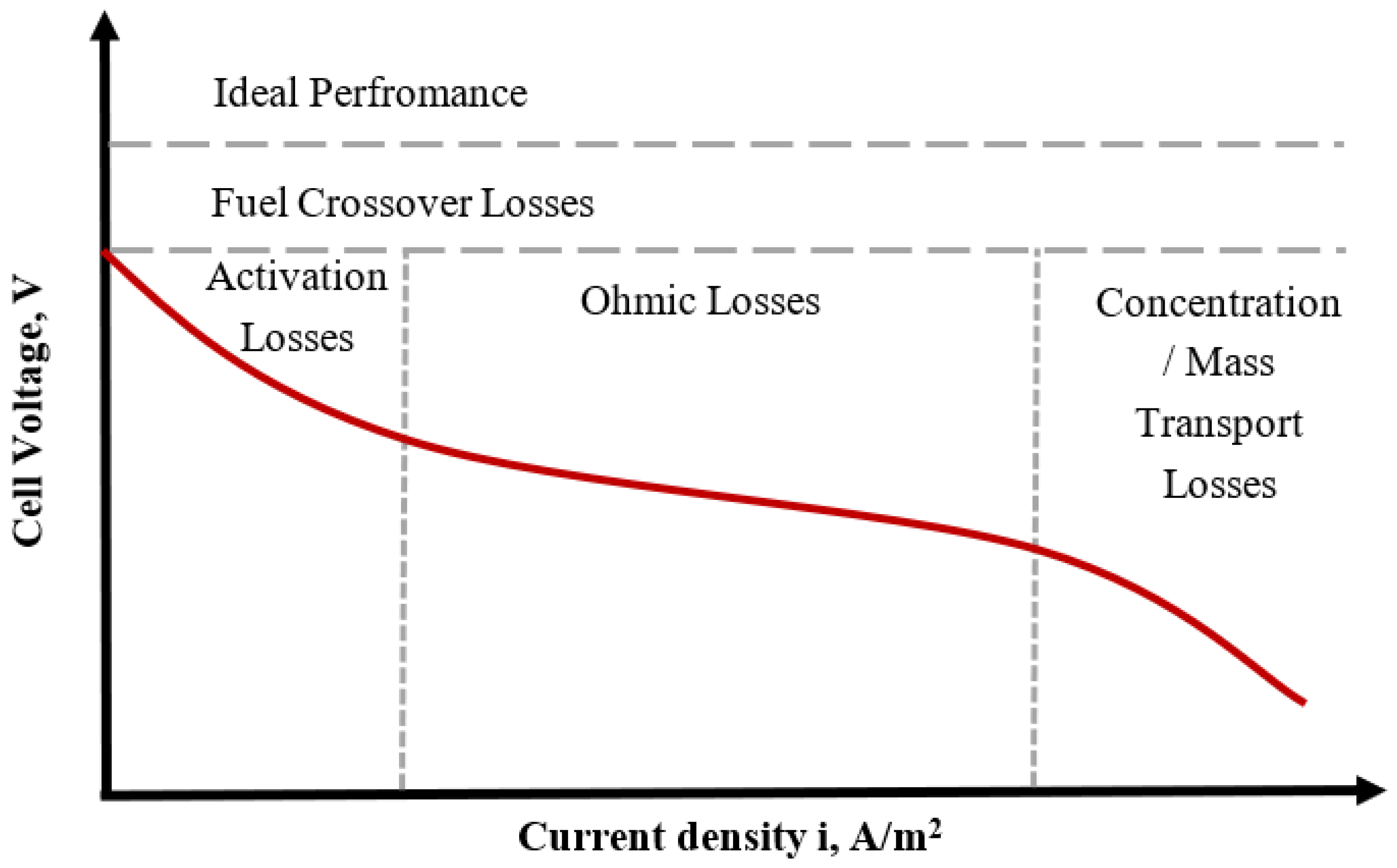
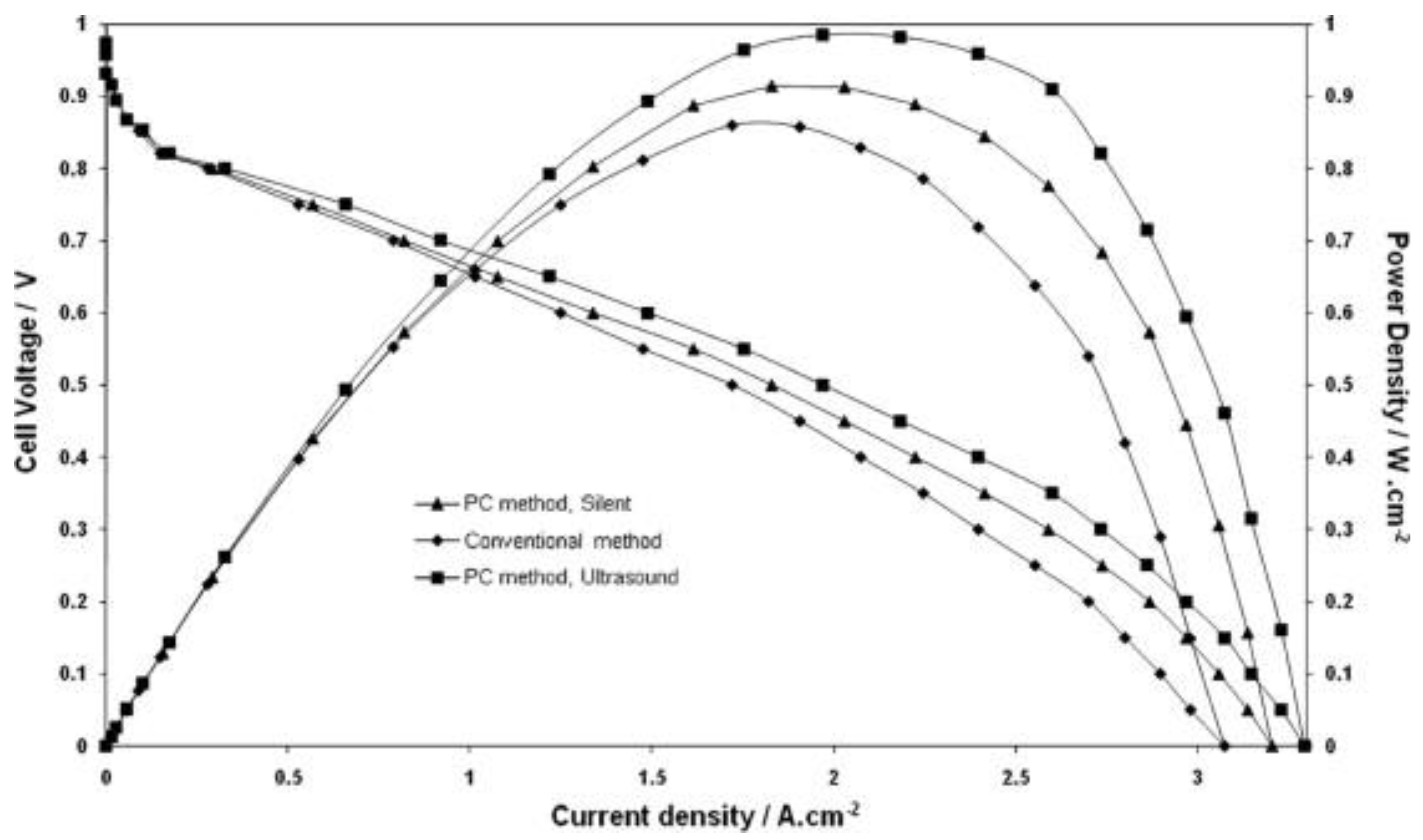
Figure 1. Polarization curve with the electric losses’ regions encountered with the operation of PEMFC (adapted from [28] (license no. 5172430728078)).
Energies 15 04949 g001
The commercialization of PEMFCs implies that the cost of the device coupled with the system operating characteristics must be in tandem with existing technologies such as conventional combustion engines. Hydrogen generation is also key in reducing the overall operating cost as well as the efficiency of the entire system. Another cost driver is the balance of plant (BOP) costs to support the stack. The common BOP of a PEMFC includes the inverter, humidification unit, hydrogen storage unit, heat exchanger, air compressors, cooling units, and batteries. Several researchers have conducted studies to estimate the cost of the PEMFC stacks and systems in recent years. The manufacturing costs’ assessment of 5 and 10 kW PEMFC stacks at different production volumes were reported to the United States Department of Energy US DOE [30]. The analysis used an active area of 200 cm2 and 400 cm2 for 6 kW and 12 kW stacks, respectively. The cost summary of individual components’ costs per stack is shown in Table 1 for production capacities of 1000 and 50,000 units. The table shows that MEA is the dominant cost item with about 67%, dropping to 45% upon increasing the production capacity from 1000 to 50,000, respectively, for both stack capacities, which is almost a 22% drop. The table also shows a drop of about 70% in total cost upon increasing the production capacity from 1000 to 50,000 unit.
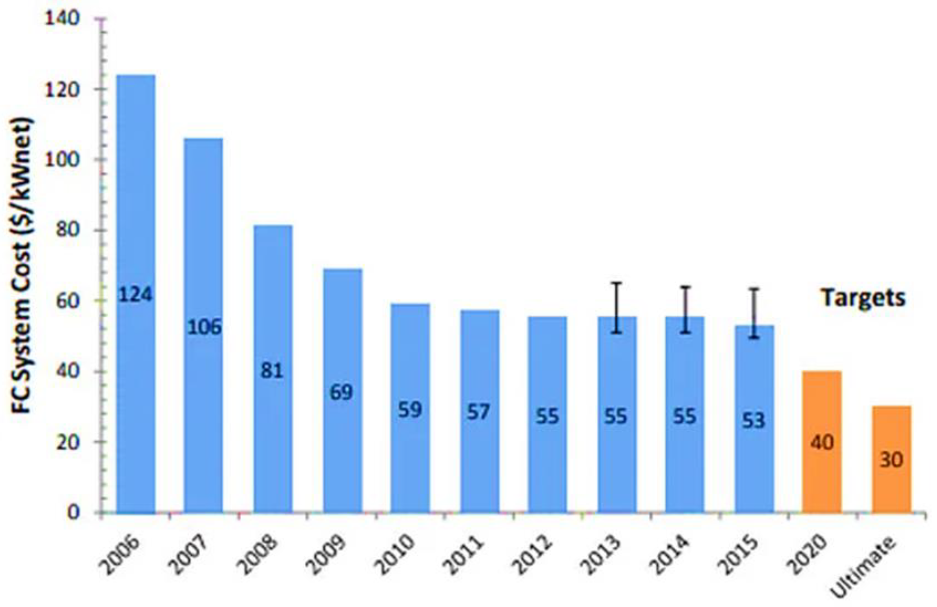
Strategic Analysis, Inc. has prepared an estimation in terms of cost for an 80 kW PEMFC (500,000 units per year) [31]. In its modeling, it projected the cost of the stack to be 53 USD/kWnet at the maximum manufactured volume and under the system, cost-optimized conditions of 0.659 V/Cell. Figure 3 illustrates the modeled cost based on a high production volume (500,000 units/year). The main drivers in the cost reduction throughout the last decade are reported to be technology advancement, reduced loading of a catalyst (platinum), and reduced materials’ costs [32]. Two components are observed to be insensitive to manufacturing volumes: bipolar plates and catalysts. The reason is that these are commodity materials, which are steel and platinum, and the price is expected to rise with demand. However, the other components are dominated by both specialty materials and processing costs and, thus, are more sensitive to volume. Hence, an increase in production causes the cost of the membrane, gasket, and GDL components to decrease, while the cost of the bipolar plate and catalyst components increase [33]. It is expected that the deployment of alternative and new materials will help further the reduction of PEMFC costs. The cost analysis considered the use of state-of-art technologies, which have been demonstrated largely in the laboratory but not yet proven in the large-scale environment [31].

2.1. Membrane Electrode Assembly (MEA)

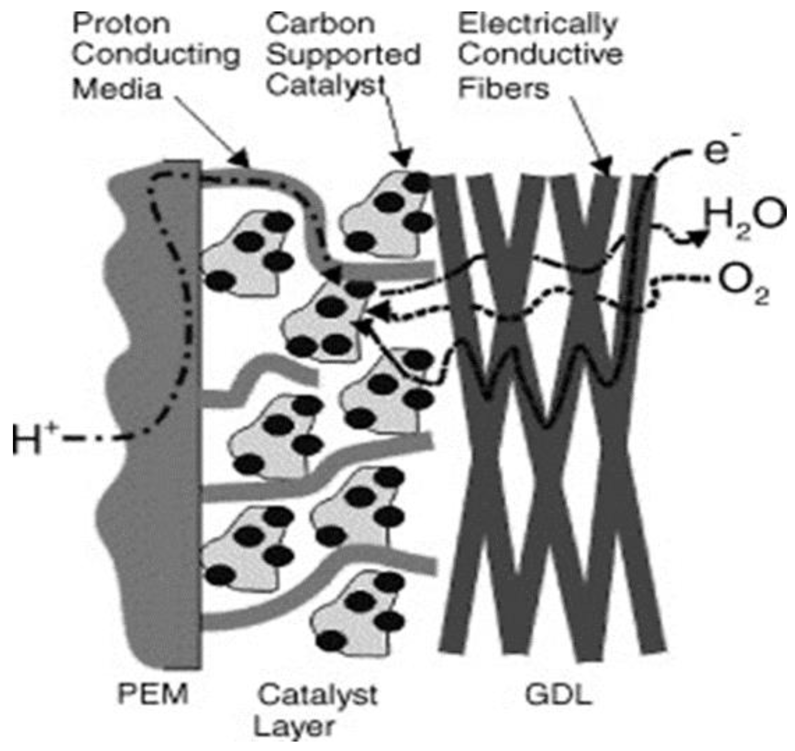
In an FC, the MEA is made up of a polymeric exchange membrane, catalyst layers, and GDL for both the cathode and anode sides, as shown in Figure 4. The material costs of the MEA rank first among other components in a PEMFC and account for around 70% of the total cost. The proton exchange membrane (PEM) is considered the center of the PEMFC. It serves as the platform for electrochemical reactions to occur. The key characteristics of the PEM include allowing the flow of protons but not electrons. They must also be designed to prevent the fuel and oxygen from mixing. Again, since most FCs are operated under varying conditions, they must be able to sustain these conditions even in unfavorable situations. The PEM must also retain a good amount of water to support the flow of protons as well as reduce membrane resistance. The size of the membrane increases whenever it takes up water; this could equally have a negative effect on the FC performance. FC water management is also key during the designing stage, as FC performance is directly proportional to membrane hydration [35]. This is usually subject to water uptake of the membrane and the water contents of the reactants, i.e., concentration, rate of formation of product water from the reaction, operating temperature, and electro-osmatic drag coefficient. A major development in the membrane field was achieved in recent years; generally, the novel polymeric membranes can be classified under five different categories, as follows [36]:
  • Perfluorinated membranes, such as perfluorosulfonic acid;
  • Partially fluorinated, such as styrene grafted and sulfonated poly(vinylidene fluoride);
  • Non-fluorinated, such as the incorporation of a sulfonic acid group into aromatic polymers, e.g., sulfonated polybenzimidazole, polyimides, and polyphenylene;
  • A non-fluorinated composite, such as acid-doped poly benzimidazoles;
  • A perfluorinated composite, such as compositing PTEE with Nafion material.
Figure 4. Schematic diagram of membrane electrode assembly [37] (open access).
Energies 15 04949 g004
Nafion is presently the predominantly used PEM. It is a perfluorosulfonic acid (PFSA) material. DuPont was the first manufacturer of this type of membrane, in the 1960s, while optimizing a Teflon-based material, which led to the discovery of Nafion [38]. The sulfonic acid group SO3H in Nafion allows the transport of protons when exposed to water as it changes to the hydrolyzed form SO3-H3O+, thus increasing the protonic conductivity across the material. The material is prepared through the copolymerization of a perfluoro (alkyl vinyl ether) with sulfonyl acid fluoride and tetrafluoroethylene (TFE). The product is a polymer that can be extruded into films that undergo treatment with hot aqueous NaOH. Upon treatment, it produces sulfonate groups (-SO3Na) being converted from sulfonyl fluoride groups (-SO2F). This is in salt form, which then converted to acid (sulfonic acid -SO3H). To cast Nafion to a thin film, this could be done by subjecting it to alcohol and heating up to 250 °C in an autoclave [39]. A major obstacle when considering the commercialization of Nafion is the high material and production costs [40]. The current cost of this material is 800 USD/m2 [41]. Commercial Nafion membranes are available at different thicknesses, such as 25, 50, and 183, μm as shown in Table 2 for some versions. The thinner versions of the materials are ideal for PEMFCs to decrease ohmic resistance, whereas the thicker ones are ideal for direct methanol FCs’ (DMFCs) applications to minimize methanol crossovers [42,43,44].
Due to the high demand for an enhanced stability and performance Nafion membrane, modifying the thickness and weight as well as processing approaches is a key area of continuing exploration [46,47,48]. Furthermore, improving the PFSA mechanical characteristics is carried out by reinforcing it with polytetrafluorethylene (e-PTFE). This approach supports the utilization of ionomers with weaker mechanical characteristics. The reinforced membranes have proven to have higher strength and durability compared to non-reinforced membranes. In a study, the preparation of a Nafion membrane was done using Nafion solutions and a support material such as porous PTFE membranes. The membranes were produced by inserting the porous PTFE membrane in the Nafion solution. The membranes produced on testing were discovered to be highly stable both thermally and mechanically at a lower cost [49,50].
Several researchers have made attempts to modify the surface of the Nafion membrane to improve its performance. Plasma etching of Nafion has been shown to increase the surface roughness and decrease permeation, hence enhancing the PEMFC performance. One study showed an increase in performance of 8% in the open-circuit voltage, and current voltage was achieved after the modification of Nafion-212 by plasma etching [51]. Compositing Nafion with different inorganic materials was also investigated [52,53]. The work concluded that the composite membrane turned to exhibit higher ionic conductivities than pure Nafion membranes. Nafion and silica sulfuric acid were used to prepare composite membrane and, on testing, were judged best in terms of conductivity compared to bare Nafion membranes [54]. In another study, by Zanchet et al. [55], composite membranes were made when zeolite fillers were embedded in Nafion. As a result of the zeolite presence, differences were noticed in conductivity, selectivity, and methanol permeability compared with pure Nafion.

2.2. Catalyst

The catalyst layer, as shown in Figure 5, is the small region between the membrane and the substrate that is conductive in nature (e.g., carbon paper) and serves as a platform for a chemical reaction to occur [56]. Platinum or platinum alloys are the most efficient and commonly used catalysts developed at both research and commercial scale. The porosity of the catalyst support material must be high to support the flow of the reactants to the reactive site [57,58].
The oxygen reduction reaction (ORR) that occurs at the cathode is usually slow and represents one of the major voltage losses because of high reduction over-potential [60,61]. Over-potential for hydrogen oxidation reaction (HOR) is lower at the anode. Electrochemical impedance spectroscopy (EIS) is used as an effective tool to determine the performance of a fuel cell [20]. For many practical applications, hydrogen feed may contain traces of carbon monoxide (CO), more specifically, when produced through reforming methods, which can adversely affect the performance of the PEMFC by blocking the catalytically active sites, which then decreases the reactivity and poisons the catalyst. One of the technical challenges, as reported by Wee et al., includes developing a catalyst capable of tolerating up to 50 ppm CO [62]. Table 3 shows a typical catalytic material for a PEMFC.
One of the effective ways of reducing the catalyst cost, and specifically for ORR, is to enhance the catalyst performance by deploying alloy catalysts such as PtCo, PtNi, etc. [77,78]. Results have shown that a Pt alloy with third transition metals improves the kinetic activity due to various factors such as the suppression of Pt oxide formation [79] and a reduced Pt-Pt neighboring distance [80]. Another approach is to use a hybrid cathode catalyst (HCC), which contains an electrochemically active nitrogen-doped carbon support with Pt catalyst. The HCC is considered to be a promising catalyst for ORR with high catalytic activity, as reported by Gong et al. [81]. The nitrogen-doped carbon is also an inexpensive alternative material and has been vastly investigated in recent years. Various types of nitrogen-doped carbon have been explored for their ORR activity [82,83,84]. Additionally, the nitrogen-doped carbon with PtRu showed higher catalytic activity and higher CO tolerance as compared to Pt-only catalysts [85]. Kim et al. described a direct synthesis process of a nitrogen-doped carbon aerogel (NCA) [86]. In their work, they showed that the proposed synthesis process offers better electrochemical performance with a higher catalytic active area and activity compared to Pt/C aerogel, which is synthesized by the conventional reduction method. The subject of research currently being conducted in the context of a catalyst layer for a PEMFC is mainly concentrated in the following two areas:
-
The reduction of catalyst cost per kW, e.g., the economic use of the catalyst content, increasing catalyst durability, finding alternative catalyst materials, etc.
-
A tolerance to carbon monoxide and sulfur species present in hydrogen feed as impurities [87].
Due to limitations with platinum resources, higher cost, and sensitivity to poison compounds, tremendous efforts were made for developing and enhancing the stability and activity of non-platinum catalysts due to their potential lower cost [88]. Non-Pt PEMFC catalysts include transition metal oxides such as Fe, Co, Ni, and Mn oxides [89], as well as Cr- and Ru-based catalysts [90]. Even though extensive work has been performed in this field, only a few catalysts have been shown to be a promising replacement for platinum in PEMFCs. Improving the performance of other inexpensive/abundant catalysts is dependent upon the loading. Increasing loading is more likely to upset the triple-phase boundaries that will cause active catalyst sites to reduce. An approach that is often used to develop non-Pt catalysts is the application of transition metal nitrides and carbides [91]. These materials were proven to have higher CO tolerance as compared to Pt catalysts. Additionally, tungsten-based materials exhibited similar catalytic properties as Pt-based metals. A non-platinum catalyst application in FCs was critically reviewed by Zhang et al. [92].

2.3. Gas Diffusion Layer

The gas diffusion layer (GDL) is a porous layer that provides an even distribution of the reactants on the surface of the MEA and is typically made of carbon cloth or paper, typically 0.17–0.4 mm in thickness [93,94]. Carbon paper (CP) is typically too rigid and fragile to be wound on typical rolls and, thus, is not suited for high production volumes, whereas carbon cloth (CC) is naturally more flexible and can endure high-pressure loads [95].
Moreira et al. investigated the effect of GDL media on cell efficiency using both CC and CP following a detailed methodology in the production of the GDL [96]. A conclusion was, therefore, deduced, citing CC as being properly positioned as a GDL compared to CP due to its characteristics. GDL mechanical characteristics have also been reported with more emphasis directed towards the effect of the clamping pressure on cell efficiency [97,98]. The research work concluded that the uniformity of the reactants revolves around the intrusion through GDL, which eventually reduces FC performance and durability. Increasing the clamping pressure limits the mass transport of reactants. The GDL plays an essential role in avoiding water flooding in the membrane layer from electrochemical reactions [99,100]. Enhancing these characteristics implies more optimization of the GDL; this was executed by coating the GDL with another layer that is porous in nature, i.e., a micro porous layer (MPL) (e.g., fluorinated ethylene propylene or PTFE) [101]. Several studies concluded that the employment of an MPL lowers water saturation and improves the transport of water molecules formed in the adjacent catalyst layer [102]. In addition to water removal, the MPL has proven to minimize electrical resistance of the catalyst layer and serve as a barrier to stop particles at the catalyst from penetrating through the GDL, thus leading to increased catalyst utilization [58]. Furthermore, some authors have investigated the materials, designs, and characterization methods for GDLs in PEMFCs [103]. The impact of varying carbon powders as an MPL on cell efficiency has been investigated, and acetylene black was proven to perform better, providing the highest cell performance. Wang et al. suggested a new MPL, developed using composite carbon powder that is placed on both sides of the GDL [104]. The results showed that this concept is capable of delivering good transport of reactants and liquid water.
It is noted that, in the literature, GDL reports in terms of numbers are lower in comparison to other PEMFC components. This indicates that the currently employed GDL is not perceived as a critical component responsible for losses in the cell. However, it is expected that the GDL will receive more attention as focus moves towards the cold start and stability of the GDL to withstand dealing with liquid water under various conditions. Cost considerations could also be another area of research, as this component is the cost driver in MEA manufacturing and represents a substantial cost item of the overall MEA cost at 50,000-unit production volume [105]. The main functions of the GDL, besides allowing reactants to reach active catalyst sites, can be summarized as follows [105]:
  • Product permeability: It serves as an exit point for the elimination of by-products from the cell.
  • Electronic conductivity: It allows the flow of electrons.
  • Heat conductivity: This allows heat dissipation to other components in the cell.
  • Mechanical strength: This supports the MEA mechanically, especially when a pressure drop of reactants fluctuates between the anode and cathode flow fields’ channels, hence maintaining sufficient contact force to avoid intrusion into the channels.

2.4. Bipolar Plates

Bipolar plates (BPs) only exist in multi-cell configurations, i.e., PEMFCs with more than two cells, and are located between successive MEAs. They, therefore, serve as a current collector in many other electrochemical applications. BPs also incorporate the flow field channels of the reactants in their surface on both sides. Furthermore, BPs represent a major part of the total weight of the PEMFC stack, with about 80%, and, hence, play a role in affecting the stack power density [106]. Most authors have reported that BPs should exhibit certain characteristics to improve the performance of the FC [107,108]. These include:
  • Allowing the easy flow of electrons.
  • Being impermeable to gases: to prevent leakage of reactants and, thus, increasing the utilization level.
  • Providing adequate strength: to prevent the cracking and crushing of plates at a high compressive force.
  • Being thermally conductive: by housing drilled internal cooling channels for the heat exchange fluid to flow and, thus, allowing the generated heat to be removed from the system.
  • Having corrosion resistance: due to the acidic condition of the MEA, the BPs are more likely to be corroded easily and, hence, must be able to sustain these conditions.
The US DOE has set specific targets for the properties of BPs for the wide commercialization of FCs; this includes flexural strength of <25 MPa, area-specific resistance of <30 mΩ/cm2 at 1.38 MPa, and permeability of <2 × 10⁻⁶ cm3/s.cm2 [109].
The last decades have seen several research activities conducted in FCs driven by the improvements of the flow plate design; this is often linked to the type of material used during the manufacturing process. The different materials suitable for BPs in FC applications are as follows.

2.4.1. Graphite Material

Pure graphite has traditionally been selected as a candidate material for BPs because it is stable even under varying chemical conditions. Additionally, the conductivity of this material is high (144 S/cm) compared to the others, hence making it suitable as BPs [108]. The limitation in the application of graphite as bipolar plate material has to do with the difficulty in working with it due to its crumbling microstructure and uneven geometry [110]. Moreover, graphite plates have to be coated to be impermeable to reactants as the material is porous and brittle in nature.

2.4.2. Metallic Bipolar Plates

Metals have better machining characteristics and improved electrical conductivity, unlike graphite. One of the most explored metallic materials for BPs is stainless steel [111,112]. It is relatively cheap and easy to shape. The ability to use this material in thin sheets (around 0.5 mm) makes it attractive for applications that require a low volume FC stack. Stainless steel under harsh chemical conditions is not stable, hence forming chromium oxides on its surface as a passive film. This film prevents electrical conductivity to and from the MEA, causing polarization losses and, hence, reducing PEMFC performance [113]. Corrosion issues in stainless steel also pose a threat for it to be used as a BP because corrosion causes the dissolution of stainless steel components, which leads to poisoning the catalyst and membrane. A convenient approach to prevent the corrosion of BPs is the application of the surface coating process. Deploying a thin surface metallic coating decreases resistance and reduces the contamination of the membrane; however, this process is often costly [114]. Some researchers have shown that contact resistance decreases as nickel or chromium content in stainless steel increases [115,116]. Therefore, an optimized version of stainless steel BPs can be achieved by changing the chemical composition of the alloy. From a production aspect, flow field geometries are influenced by the chosen process method as well as the operating requirements such as gas distribution and pressure drop. Because flow field channels require precise structures in the millimeter range and high aspect ratios (height/width), the existing forming methods such as stamping and hydroforming of coated steel possess a challenge to meet these requirements.
Another BP material choice is aluminum. This material has gained attention because it is lightweight and cheap in comparison to most metals. However, aluminum is more liable to corrosion attack than is stainless steel. The application of gold coating to aluminum can reduce the degree of corrosion. Nevertheless, due to the large gap between the thermal expansions, the coefficient of gold and aluminum micro-cracks in the coat is more likely to form with time [117]. Woodman et al. worked to lessen such micro-cracks and showed encouraging results [118]. They deposited a coating layer with an intermediate thermal expansion value between gold and aluminum, and the micro-cracks were remarkably reduced. Metals have higher corrosion rates, of about 250 and <100 μm/year for aluminum and stainless steel, respectively, while gold has a value of <15 μm/year, which is comparable to that of graphite [118].

2.4.3. Carbon Polymer Composite Material

Composite materials, such as graphite with polymer binders, are more suitable for matching the desired properties set by the DOE. Additionally, the fabrication of the flow and cooling channels using these materials is less complicated with current manufacturing technologies. These composite materials are made of polymers that serve as binders and a high loading of conductive filler carbon compounds that improves the conductivity and corrosion resistance. The polymers can either be thermoplastics, such as polyethylene and polyphenylene sulfide, or thermosets, such as phenolic resins and vinylester. The application of thermoplastic and thermoset resins is the future of composite BPs [119,120]. A major challenge in carbon composite BPs has to do with decreasing their resistance due to the resins. This is often achieved by treating the surface with plasma treatment, microwave carbon surface modification, and graphite coating. Lim showed how contact resistance of composite materials is improved via the use of different treatments [121].

2.4.4. Foam-Based Bipolar Plate

An encouraging alternative to channel-based BPs is the use of open-pore metal foam to distribute reactants and remove water. Investigations on foams made of stainless steel, nickel, and nickel-chromium were recently conducted [122]. The shape, size, and pore distribution of the foam have to be specifically tailored for each application depending on the dynamics of that system. The published performance data showed improved initial results of the PEMFC in comparison to conventional flow field channels’ design. However, with materials such as nickel, membrane contamination by metal ions was detected.
In an experiment by Tseng et al. [
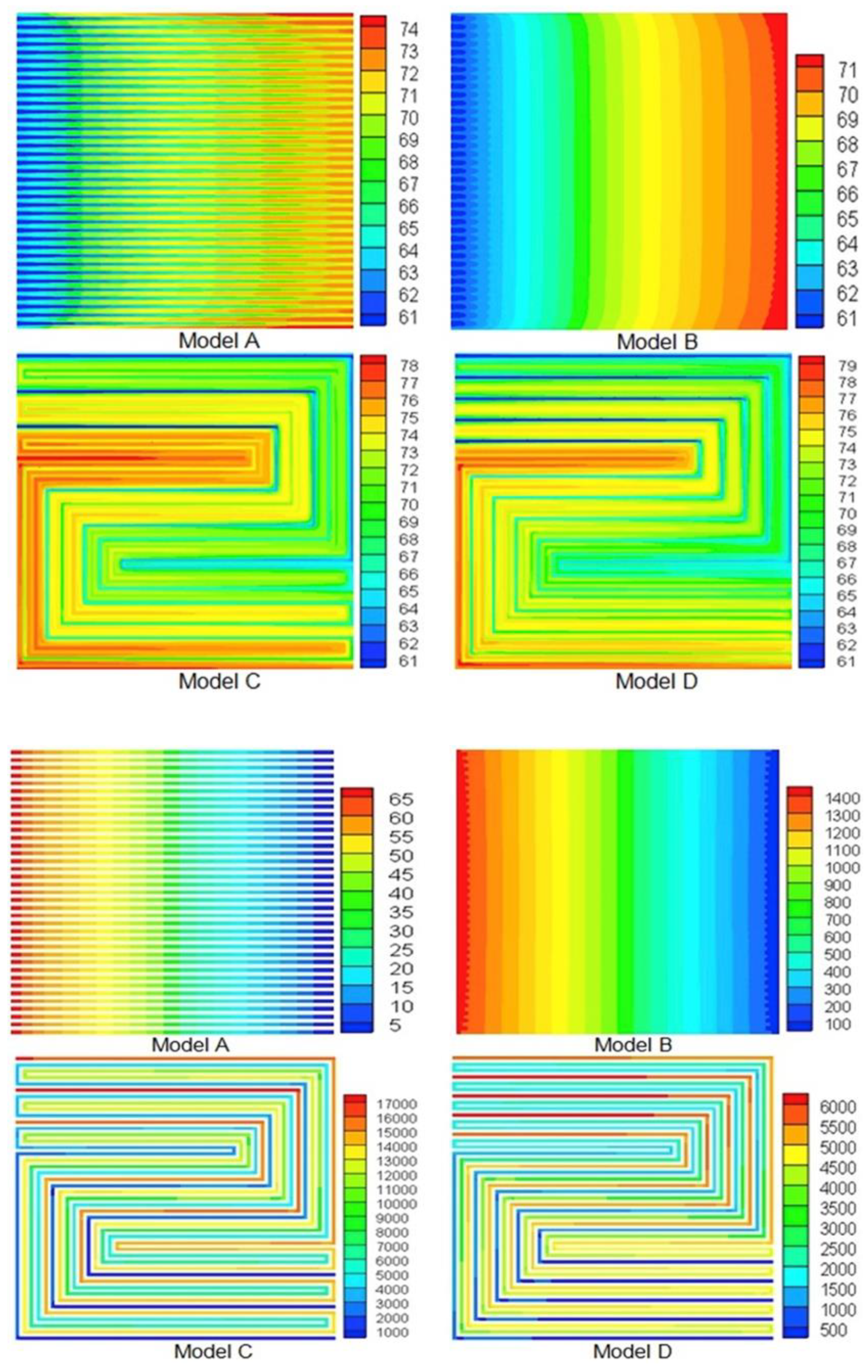
122], although it is clear that there are still several problems to be solved for flow channel plates to be displaced, important unique characteristics of foam BPs were shown, which made it a likely solution in the future. An analysis of how the effects of hydrophobic treatment, porosity, cell temperature, humidification, electrical conductivity, and air stoichiometry was performed. A comparative study between a hollow BP and metal foam BP was also carried out. It was shown that, because the porosity of the foam was high, it played down the challenges associated with mass transport, which is very common when a flow channel plate is used as a flow distributor. Metal foam is very useful to distribute a coolant fluid in the PEMFC. An investigation carried out by Afshari et al. utilized four flow field designs to ascertain their performance at varying conditions [123]. A 3D model was used for the simulation of the flow of fluid and heat transfer. Model B, which was the metal foam, was the overall best, based on the numerical figure and the computational fluid dynamics (CFD) result with regard to pressure drop and surface temperature distribution, as shown in Figure 6.
Another work by Afshari et al. compared metal foam with partially restricted cathode flow channels [80]. It was shown that the metal foam showed increased oxygen concentration, improved current density, and improved uniform distribution compared to the partially restricted cathode flow channels, which confirmed other results in the literature [122,123]. In another study, by Tseng et al. [124], metal foam was applied to high-temperature (HT) PEMFC. Comparing metal foam with a conventional graphite serpentine flow, the investigation into the effects of stoichiometry, operating temperature, and humidification was performed using AC impedance for analysis. Metal foam showed increased current density up to 20% more than the conventional graphite serpentine flow plate along with increased operating temperature and stoichiometry and overall improvement in the FC performance. Open-pore cellular foam proved to be better at reducing the possibility of flooding and distributing hydrogen through the catalyst layer than a serpentine flow plate for an air-breathing PEMFC (AB-PEMFC) [125]. Water management is a major challenge for various FCs, and this could be a breakthrough. Metal foam BPs is smaller and more attractive [78,83]. This assertion by these authors might be due to it having less weight and reduced complexity in design [125]. Being smaller will save space and improve its durability, making it easier to adopt the technology.
Foam BPs can be made using different types of materials. It was made initially using different types of metals [126,127,128]; however, the development of novel materials is causing a paradigm shift. Work on using porous carbon foam for flow distribution in PEMFCs was carried out by Kim and Cunningham [129]. Although metal foam has a lot of advantages when used, it also has a lot of challenges. Its problem associated with corrosion is huge due to its large metal surface [122]. Work by Baroutaji et al. [125] comparing uncoated open-pore cellular foam (OPCF) with PTFE-coated OPCF showed better performance from the coated BPs. This showed that coating can be used as a temporary solution while research continues to explore ways to solve the already identified problem [88]. Different materials are being used for coating, such as graphene in work by Ting et al. [130]. An investigation into the characteristic analysis of PEMFC with metal foam was reported by Afshari and Houreh [131]. A three-dimensional model comparison for varying flow plate geometry was also reported [132], and an analysis of a representative model and flow characteristics considering the application of foam in PEMFCs was carried out by Carton and Olabi [133].

2.5. End Plate

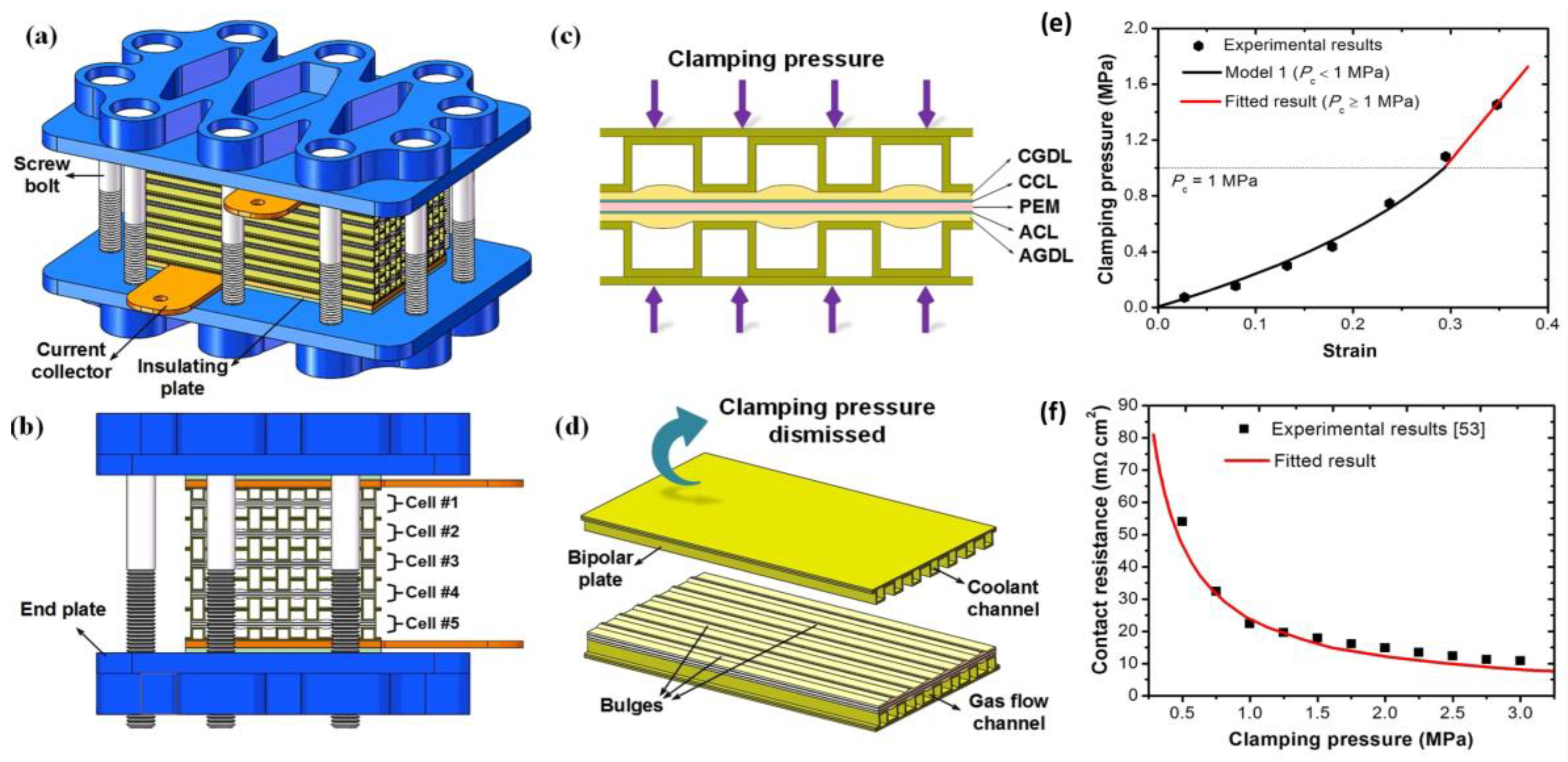
End plates are a key component of the FC and also determine the overall efficiency of the cell. Their key role is to support the FC via the supply of contact pressure evenly on the cell. Other roles include serving as the platform for the flow of reactant gases and also preventing the gases from escaping out of the cell. The bolts and nuts are also attached to the end plate. The inlet and outlet channels are also designed to be positioned on the end plate. When the end plates are assembled together in the stack, a specific torque on the bolts has to be applied. The torque needed depends on various elements such as the material characteristics of the components, the number of cells in the stack, and the number of bolts used. The aim of having a sufficient load of bolts, as shown in Figure 7, between end plates is to achieve constant pressure distribution throughout the assembled cells in the stack. The required torque for each bolt can be found by T o r q u e = F c l a m p K b D b / N b , where the clamping force is denoted as Fclamp, Kb is the friction coefficient, Db is the bolt nominal diameter, and Nb is the number of bolts [125].
Furthermore, it was found that uneven distribution of pressure over the MEA leads to uneven current density [135,136], whereas high clamping pressure results in an increase in the contact region, hence decreasing contact resistance. However, excessive clamping pressure will cause the GDL to become overly compressed, hence affecting the GDL’s porosity, which limits the mass transfer of reactants to reactive sites [137,138]. Several items of literature investigated the impact of the clamping force on FC operational conditions, such as ohmic resistance [139,140] as well as interfacial contact resistance [141,142]. Patermarakis and Papandreadis [143] reported that up to 59% of the power in PEMFCs could be lost because of contact resistance between GDLs and BPs. Lai et al. [144] simulated a 2D model of the GDL and BP. Their investigation concluded that contact resistance reduces rapidly as clamping pressure increases. Alizadeh et al. [
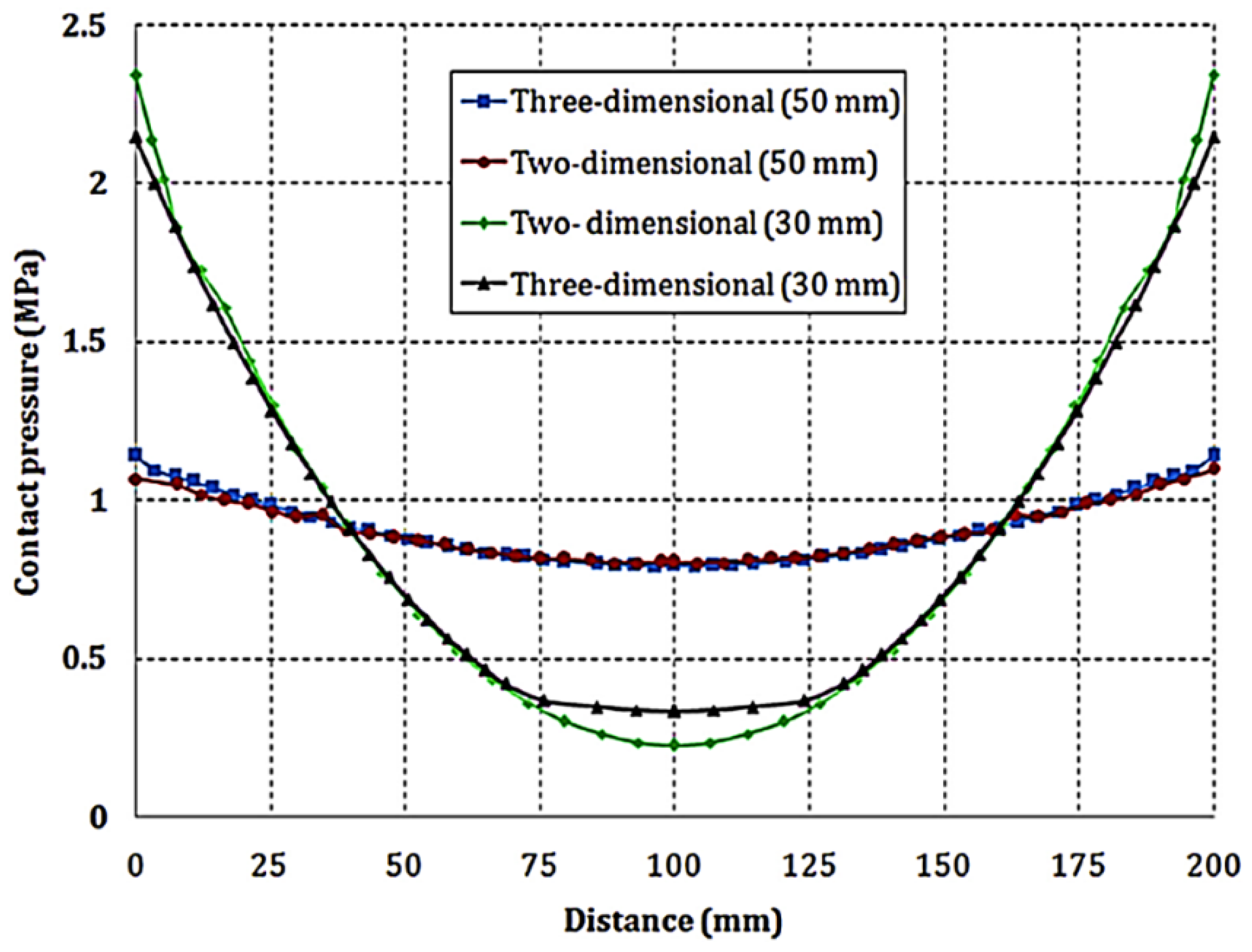
145] conducted a 2D finite element simulation based on an experimental study and compared the effect of using aluminum and stainless steel as end plate materials at two fixed thicknesses. In addition, they explored the effect of contact pressure distribution, as depicted in Figure 8.
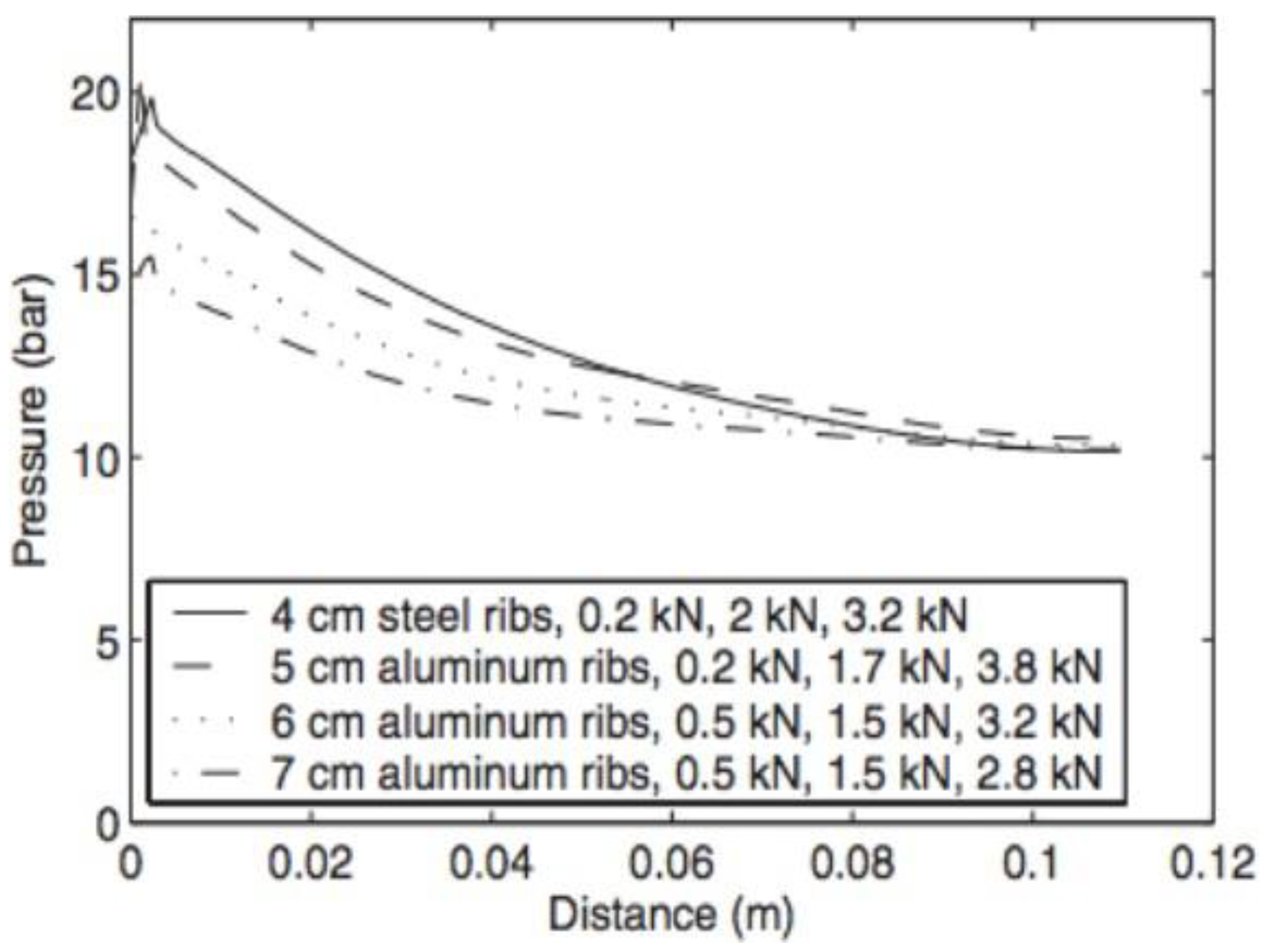
In addition, Karvonen [146] studied the effect of different end plates structures on the pressure distribution and found that more uniform pressure distribution is achieved if ribbed-plate structures were used instead of conventional flat plates. In their work, they ran a finite element analysis and verified the results experimentally using pressure-sensitive film. Their results showed that the 7 cm aluminum material ribs with optimized bolt loads were proven to give the best results in terms of the pressure distribution across the MEA to the GDL area with reduced weight. Figure 9 shows the diagonal pressure values of the different structures used in the study with the optimized load values of the bolts.
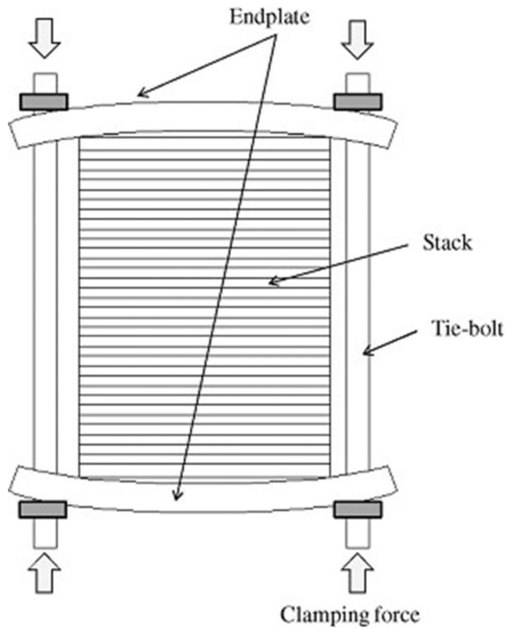
One of the major sources of uneven pressure distribution is a result of the end plates deflecting along the edges, which causes less clamping force in the middle region [146,147], as shown in Figure 10. Several researchers have proposed different designs to prevent this. Yu et al. [148] also suggested the use of a composite end plate, but with a pre-curved compliant pressure distributor material (PD). The PD that was used in their work was also made up of silicon. In their investigation, they concluded that the design method used is good to be used for advanced PEMFC end plates, not only for more uniform pressure distribution in the middle region but also for good thermal insulation performance.
The materials that are commonly used as end plates are steel alloys and aluminum. The rigidity and the strength of these metals coupled with their lower cost compared to alternative metals make them a great choice for end plate materials. From the literature, it is reported that the ideal end plate material should possess the following characteristics [146,148,149]:
  • Low-density material, to make the stack lighter and, hence, achieve high power density (W/Kg).
  • High rigidity to ensure the end plates do not bend when a high tightening force is applied.
  • Good chemical and electrochemical stability.
  • Electrically insulating to resist the flow of electrons to ensure safety and that the electrical power is not transmitted through the material, especially at high output power (50 cells or more).
  • Thermally insulating to keep the heat produced within the FC and also to prevent heat dissipation at the start.
The materials used for end plates can be classified into two types, non-metals and metals. Plastics tend to be used as end plates in miniature and small stacks as the thermal stability is not satisfactory. Metals exhibit higher mechanical strength and are more thermostable. However, the corrosion resistance and electrical insulation of metals are not adequate for PEMFC applications; the surface of metal end plates is often treated to achieve the desired properties. For instance, anodization technology is used as a treatment for aluminum end plates to provide better corrosion resistance and insulation [150]. Recently, there have been a few attempts to replace conventional metal end plates with carbon composite materials to reduce the weight as well as improve the thermal resistance, which is critical in enhancing the cold start characteristics of the PEMFC [151,152]. The merits of using carbon composite materials include high compression and tensile strength.

2.6. Gaskets

Gaskets are needed in the PEMFC system to ensure that all reactants are only flowing within their respective regions. A failure in selecting the appropriate gasket material for the application will result in the leakage or mixing of reactants. Furthermore, the durability of the gasket material is an important element to be considered, as gaskets are exposed to dynamic changes during operation such as temperature and the acidic environment of reactants. Gaskets are also subjected to compressive stress between BPs; thus, selecting the appropriate material and the right design is vital to avoid mechanical overload [153,154].
Gaskets in the PEMFC application are commonly made of cured elastomer polymers for sealing purposes as they offer distinctive advantages. These advantages include high chemical resistance, enhanced stress relaxation, and good flexibility, which make them more attractive. This class of polymer is also known to be viscoelastic, meaning that it will return to the original shape after deformation due to compression or stretching. Elastomer is an amorphous polymer made up of oxygen, carbon, and silicon with excellent properties such as large strain, permeability, and insulation [153,155]. Practically, elastomers are used as a base component with other materials to make a compound, such as a crosslinking system and filler. This improves the characteristics of the elastomers such as high tear energy, low compression set, and high tensile strength. Curing is often used to form the crosslinks between the polymer chains [156].
Different additives, e.g., fillers such as silica and carbon black, are also mixed with elastomers to obtain a suitable material strength and durability. Furthermore, anti-degradants are used to improve its aging resistance [157]. There have been some attempts to reduce manufacturing costs and assembly time by integrating gaskets to BPs or eliminating them. For instance, Lee et al. manufactured a carbon/silicone elastomer composite flow plate [158], while Lim et al. developed a gasketless BP [159].
The most commonly used materials for gaskets in the PEMFC applications include silicone rubber, ethylene-propylene-diene monomer (EPDM), fluorinated elastomers, poly-acrylate, butyl rubber, and hydrocarbon-based elastomers. Choosing a suitable material is subject to the temperature and media of the environment that the PEMFC will operate in. Yuan et al. [160] investigated the aging of silicon rubber under alternative and direct current voltages. Tan et al. [161] investigated the deterioration of different gasket materials in PEMFC, which was found to start with surface roughness and develop cracks with time. Additionally, Lin et al. [162] examined the life span of five elastomers in an aggressively accelerated PEMFC environment independent of physical durability and the cost of the materials used. They found that the fluorosilicone rubber (FSR) was the most stable material. Moreover, Frich [163] investigated the advantages of silicone elastomers as gaskets in PEMFC over other materials. Some of the common materials used as gaskets for PEMFC are summarized below.

2.6.1. Silicon Rubber

Silicon rubber is commonly employed in low-temperature PEMFCs. Its distinctive characteristics offer good thermal and weather stability, oxidation resistance, low gas permeability, and low-temperature flexibility [164]. Silicon rubber has different classes, depending upon the organic group that is connected to the silicone atom. This material has been widely used for PEMFC applications, mainly due to its softness, widespread availability, and simple processability rather than its material characteristics. However, this material is relatively expensive compared to alternative seal materials and also exhibits poor chemical resistance to acidic environments that typically exist in PEMFC. Thus, it is seen to be more applicable for short-term PEMFC applications, such as portable devices. Additionally, it has been noticed that silicone-containing species break down and chemically contaminate the membrane with time, causing mass loss and, thus, a possibility of reactants’ and coolant leakage [165,166].

2.6.2. Ethylene-Propylene-Diene Monomer (EPDM)

EPDM is by far the most used elastomer among synthetic rubbers and is becoming more popular to be used for various applications and especially for gaskets and seals. EPDM offers excellent heat and weather resistance due to the existing saturated polymer backbone. It is also available in various ranges of molecular weight, which also makes it attractive as a polymer for diverse markets. Additionally, EPDM polymers are non-polar and, hence, have good resistance to water and aqueous solutions along with low crystallinity and, hence, can accept high loading of fillers to obtain adequate mechanical properties [167]. EPDM generally has good durability in the long run in addition to being acid resistant [168,169]. An EPDM rubber polymer contains ethylene, propylene, and a diene monomer that gives a site of unsaturation for crosslinking. The composition of ethylene to propylene contributes significantly to the determination of the resultant characteristics of the rubber and is usually 2:3 ethylene to propylene.

2.6.3. Fluroelastomers

Fluoroelastomers (FKM) are special-purpose, fluorocarbon-based synthetic rubbers and are prepared from fluorinated monomers. Initially, these polymers were developed from vinylidene fluoride (VF2) and chlorotrifluoroethylene (CTFE), and, recently, tetrafluoroethylene (TFE), to enhance the fluorine level, for improving the overall chemical resistance [170]. FKM withstands most lubricants and fuels; its strength and chemical resistance are better than the other elastomers and can withstand elevated temperatures (<300 °C) [171]. In addition, FKM offers excellent resistance to ozone, oxidation, and weathering [172]. However, FKM is more costly as compared to other elastomers and is often used in applications where high performance is essential [173,174]. Under the characteristics of the PEMFC environment, this elastomer is expected to operate well even when conditions are unfavorable. However, from a manufacturing point of view, this material is not the primary choice; this is because of its poor melt processibility (e.g., injection molding) and also its low thermal resistance [169].
The durability of the sealing material needs to be predicted before large-scale production to make sure it will last for the desired lifetime. Accelerated methods of testing are, therefore, adopted to monitor the performance of such gaskets under dynamic conditions so that they can accurately be predicted. Materials’ properties can be obtained through standard test methods such as trouser tear and uniaxial tension. These tests typically follow the ASTM standards’ outlined procedure. For tensile and tear tests of the materials’ properties, ASTM D412 and ASTM D624 standards are followed, respectively. Moreover, when gasket elastomers are compressed between the BPs, they produce a restoring force, which depends on the compressive strain, aging with time, exposure to high temperature, and chemical environment. When this stress is then released, the seal will take some time to restore to its initial shape and may show permanent distortion [175]. This behavior of the seal is known as the ‘compression set’ and is of great importance in the PEMFC applications [176,177]. Thus, to study the long-term mechanical behavior, compression stress relaxation tests are often conducted to measure the restoring force. Several methods have been established to determine stress relaxation when a load is applied; the advantages and disadvantages of using continuous versus intermittent test approaches have been studied [178,179]. Furthermore, to predict the lifetime of the sealing material, accelerated aging methods (AEM) are also employed. Such methods involve increasing the reaction but not changing the deterioration mechanisms, which are likely to arise with the long-term use of the material [180].

3. The Manufacturing Method of PEMFC

Finding low-cost methods of manufacturing different PEMFC components is key to achieving the goal of PEMFC commercialization [181,182]. The manufacturing cost will be playing a significant role in realizing large-scale manufacturing of FCs, hence making them a feasible option as compared to conventional power supply devices.

3.1. Membrane Electrode Assembly MEA

There are mainly two approaches for fabricating MEA, which depend on the catalyst ink deposition method adopted. The first approach involves hot pressing the catalyst layer on the gas diffusion layer. This technique in some literature is referred to as a catalyst-coated substrate (CCS). The second approach, a catalyst-coated membrane (CCM), involves the deposition of the catalyst layer on the membrane directly. To eliminate the challenges associated with the swelling of the membrane, a new method was proposed, the decal transfer method (DTM). The catalyst is laminated on the membrane with the aid of a Teflon film via pressing. Research work was conducted using the methods discussed above to determine the technique that yielded the maximum cell efficiency, as shown in Figure 11. It was deduced from the investigation that the DTM produced the best cell efficiency [183].
With more than 170 years since the emergence of FCs, one of the main obstacles in the fabrication of PEMFCs’ MEAs is comprehending and optimizing the electrode structure with maximum utilization of a catalyst. The ink-based electrode deposition methods were developed to the extent that the industry is at the onset of setting up production plants to make MEAs. Mass production of MEAs will mostly be geared for planned stationary applications and, subsequently, automotive applications. The current research in this field is to further develop and understand conventional inked electrodes as well as to find alternative techniques to manufacture electrodes with an advanced level of microscopic structural control and to reduce platinum loading. Catalyst deposition methods with some of the used techniques are summarized in Table 4.

3.1.1. Hand Painting

Hand painting by far is the most commonly deployed method to deposit catalyst ink, especially in laboratory-scale practices. In hand painting, the procedure of massing several times, painting, and drying have to be repeatedly iterated before the final gas diffusion electrode is obtained. This results in increased labor costs and unsteady quality control, and, thus, is hard to be scaled to larger production volumes. Furthermore, a more uniform catalyst layer is hard to achieve using this technique [188].

3.1.2. Spray Painting

Spraying is another popular method for catalyst layer fabrication [189]. In this technique, the catalyst layer is sprayed with an airbrush using a pressurized feed of an inert gas such as nitrogen. To attain the required loading and thickness of a catalyst, the spraying process is conducted in multiple steps. The weaknesses of this method include non-uniformity and frequent clogging of catalyst particles. However, with the use of computer-aided controlled sprayers, more uniform layers can be obtained.

3.1.3. Sputtering

Sputtering is a physical vapor deposition (PVD) technique and is widely recommended for integrated circuit manufacturing. In this technique, catalyst ink is placed in the source material (target) inside a controlled-environment chamber and argon plasma is used to deposit the atoms into the substrate. This process is capable of depositing ultra-thin catalyst layers, up to 1 μm in thickness, and, thus, the ionomer in the ink mixture is removed. However, the literature shows that MEAs prepared by sputter depositing showed a reduced performance compared to other fabrication methods. It is mainly due to the variation in catalyst layer thickness and particle size [190]. Despite the ability of this method in directing the deposition of the catalyst layer, the main obstacle of this process is the inability of the platinum to stick to the substrate, which, in effect, leads to a high possibility of wastage. Moreover, for large-scale production, this process requires a huge investment due to costs associated with ultra-high vacuum equipment, platinum targets, and clean rooms. Fofana et al. [191] investigated the use of this technology for the reduction in platinum loading in the cell. It was concluded that using three layers gave the best cell performance.

3.1.4. Inkjet Printing

Towne et al. [192] explored the feasibility of producing gas diffusion electrodes for a PEMFC’s MEA via the inkjet printing technique. The approach yielded positive results with minor challenges observed. Some parameters were difficult to control manually such as drop size, print head speed, etc. The nozzles of the print heads were between 10–20 µm. Grounding the catalyst power with the aid of ball mills can significantly curb this challenge. It is recommended that the size of the power must be between 100–500 nm to prevent coagulation.

3.1.5. Electrospraying

Electrospraying is an innovative, electrically assisted catalyst deposition method for MEA fabrication. Catalyst ink is forced to flow from a capillary tube using electric fields onto the substrate. High voltage in the range of 3–4 kV is applied between the tube as well as the substrate, and the set value is dependent on ambient conditions. Droplets of the catalyst mixture reduce in size before touching the substrate as a result of Coulomb expansion (division in particles due to high charge density); hence, thin layers can be achieved. This process has demonstrated an enhanced catalyst utilization compared to conventional methods such as hand and spray painting, primarily due to morphological and structural improvements. Martin et al. [188] used this technique to prepare a catalyst layer to be used for PEMFC cathodes. They concluded that catalyst utilization (power density relative to platinum loading) was greater for electrodes made with electrospraying.

3.1.6. Electron Beam Reduction

This technique applies the concept of reducing catalyst species’ ions via direct electron-beam bombardment to achieve better electrode penetration depth and distribution. High-energy electron beams are used to discharge the ionic catalyst mixture from a transmission electron microscope (TEM). The electron impact causes catalyst ions to undergo a reduction process, which, as a result, creates nano-scaled catalyst particles. Pai et al. investigated the efficiency of a single cell MEA using this approach and compared it with the sputtering technique [193]. Both I–V and power density curves were obtained, as shown in Figure 12. As can be seen from the curves, electrodes made from electron beam reduction exhibited higher efficiency than the sputtering technique, corresponding to an optimal power density of 0.56 W/cm2 and 0.36 W/cm2 for the former and latter, respectively. This is mainly because the electron beam method offers larger active surface areas and less material loss during fabrication in comparison to sputtering [193].

3.1.7. Sonicated Spray

In this technique, ultrasonic and sonoelectrochemical technologies are utilized [194,195]. The catalyst inks in this process are first injected in a sonicated syringe before atomization in a nozzle and then sprayed. Implementing this technology has attracted many researchers in different industries as it was found it leads to an increase in the rate of reaction. The effect of ultrasound on the chemical reaction and the catalyst surface can be attributed to the ‘cavitation’ phenomenon. Additionally, with this method, the catalyst inks can be distributed more evenly and a better catalyst utilization with less loading as compared to other spray methods can be achieved [196]. They reported that the PEMFC exhibited a better performance compared with electrodes prepared by galvanostatic pulse and screen-printing methods, as shown in Figure 13.

3.2. Fabrication of Bipolar Plates

It is important when manufacturing BPs to consider the cost effectiveness and efficiency in production to make it feasible at a commercial scale. The manufacturing process of BPs usually involves metal plate fabrication such as welding of both anode and cathode plates, forming a tinny plate with the proper flow field channels [197]. The conventionally used material as BPs is graphite because it is corrosion resistant and light and has excellent thermal and electrical properties. However, its brittle nature, poor mechanical properties, and hard and costly machining have driven researchers to look for more efficient manufacturing methods, such as injection and compression molding. For instance, Messinar et al. showed a compression molding technique where the graphite blend was molded from 10 °C to 100 °C at variable compression forces [198]. Currently, several researchers are paying attention to graphite/polymer composites because they can easily be manufactured and are mechanically stable [199,200]. Lee et al. patented and demonstrated a method for manufacturing a composite separator using graphite foil that is bonded to a carbon fiber-reinforced composite material [201]. The different BPs’ fabrication techniques are summarized as follows.

3.2.1. Micro-Stamping Process

The flow field in BPs requires a high level of precision due to the small dimensions of channels, which are typically 1 mm [202]. The micro-stamping method is considered to be a convenient choice for metallic BPs’ manufacturing mainly due to its ability to form multiple flow channels, which increase the distribution of reactants. In the micro-stamping method, high accuracy dies with micro-machined channels are applied to deform metallic sheets. This fabrication method has the merit of being cheap with high productivity. Dundar et al. explored the impact of stamping process constraints, such as stamping force and punch speed, on the interfacial contact as well as corrosion resistance [203]. They concluded that the lower the stamping speed, the higher the scratches on the surface, which increase the rate of corrosion. It, therefore, implies that high-speed stamping is ideal for fabricating FC flow plates as well as improving the rate of production. Hu et al. investigated BPs’ imperfections by examining thickness variations with the use of finite element analysis [204]. The simulation took into account the variable process conditions such as the dimension of flow channels’ radius of punch, punch speed, and angles of die and draft. Furthermore, they compared the results of their work with experimental results for stainless steel metal sheets and found they showed good accordance. The results showed that an SS304 sheet cracks at a relatively high speed and wrinkles at a very low speed, with better formability at the speed of 0.1–1.1 m/s.
Khatir et al. explored the manufacturing process for an SS316L metallic flow plate using the stamping method with a thickness of 0.1 mm [205]. They compared two cases of a forming process, uniformity of the channels and filling flow channels’ depth with and without lubricants. Nylon polypropylene lubricant was chosen because of its high tensile strength and low thickness. Their results showed that the application of a lubricant increased the depth and amount of filling of flow channels as well as the amount of filling significantly. In contrast, with a lubricant, sheet metal forming was easy and of better thickness uniformity.

3.2.2. Hydroforming Process

This technique is a specialized type of die molding and it operates using a highly pressurized liquid media to form defined work-piece geometries. The advantages of this process include its cost efficiency, improved surface quality, higher drawing ratio, the capability of generating complicated shaped parts, and fast production cycle [206]. In this method, metal sheets are placed between two dies, which form the close cavity. This is then followed by a push of the pressurized liquid media into the cavity. Mahbunpachai compared stamping and hydroforming techniques and reported lower surface roughness and lower dimensions’ variation with the hydroforming process [207]. Additionally, Peng et al. developed a finite element model for demonstrating the risk of wrinkling and rupture of BPs’ metal sheets, stressing the role of optimizing BPs’ dimensions for improved cell efficiency and lower cost [208]. Additionally, Osia et al. suggested an additional step of stamping in the hydroforming fabrication of BPs with a finite element model to verify results [209]. Their results showed that a hydroformed metallic BP’s convex pattern has a better thickness distribution and filling percent than a concave pattern.

3.2.3. Rubber Pad Forming Process

It is an innovative stamping process for shim sheets and is mostly used in the aeronautic, energy, automotive, and electronic industries [210]. Recently, this process was employed for the fabrication of BPs. The differences between this process and the conventional stamping techniques are that it only involves the manufacturing of one rigid die per the part shape and the rubber pad replaced the other rigid die [211]. Liu et al. explored the rubber pad forming method for manufacturing SS304 BPs [212,213]. They concluded that the rubber pad forming technique is a practicable technique for BP fabrication. Jin et al. investigated the fabrication of thin Ti sheet BPs [214]. The sheets had a TiN film deposited on it using a plasma reactive magnetron sputtering process. They found different constraint parameters such as punch pressure, punch velocity, rubber hardness, and rubber thickness using a serpentine microchannel with an S-shape. Additionally, with an optimized condition, the impact of draft angle on the punch for Ti BP forming depth was evaluated. They noticed that there was an increment in the channel depth of the BPs and the channel draft angle inside the punch as a result of the blank that was filled easily.
Similarly, Elyasi et. al [215] reported the efficiency of concave and convex forming patterns for 0.1 mm SS316 BPs, using rubber pad forming techniques, and an appropriate pattern was established. They studied the effects of various forces’ manufacturing of the microchannel filling. Their results pointed out that the convex pattern would form a deeper channel than the concave pattern. Son et al. evaluated the fabrication of aluminum 1050 alloy BPs using rubber pad forming [216]. The aluminum plate was developed by using a 200-ton hydraulic press; process parameters for this technique such as punch speed, rubber thickness, plate pressure, and press pressure were examined. They concluded that the right thickness is necessary for this technique because the thickness does affect the forming depth of the material. Elyasi et. al studied a die clearance in the rubber pad forming process for SS316L [217]. Two die sets of various clearances were used to study the influence of die clearance on the depth filling. Their results showed that when the die clearance is introduced between the matrix and punch die it increases the depth filling uniformity.

3.2.4. Selective Laser Sintering (SLS)

This approach is a fast fabricating method that involves a computer-aided design (CAD) model that is 3D constructed by an additive manufacturing process. The SLS is advantageous over traditional techniques because it is easy to work with, even with a difficult geometry design. The SLS method is among the solid freeform fabrication techniques. When starting to use the SLS method, a 3D model is used to represent the part that will be disintegrated into a 2D model, known as sintering planes, and later transferred into the SLS machine [218]. SLS offers a way of fabricating graphite composite BPs, which helps considerably in reducing the time and cost of production and gives it an advantage over the conventional method (injection molding and compression molding). The SLS process is a mixture of binder particles and graphite, which is scanned through a laser. Guo and Leo studied various graphite materials and carbon fiber embedded together through SLS [219]. The results showed that the BP produced using the SLS process has a lower density than the conventional ones. Chen et. al fabricated a PEMFC current collector using SLS techniques. They observed that the computer simulation gave more information about the FC operation, which is not possibly obtained by experimentation. It was concluded that this technique allows flexibility in fabrication and eliminates the constraint that was imposed by conventional fabrication [220].

3.3. End Plate Fabrication

The fabrication of metal materials for end plates is commonly conducted through near net shape casting (NNS). The NNS is a collection of approaches that leads to a higher surface finish, thus reducing any requirement for machining and grinding, which lower production costs [221]. There are many casting techniques including sand, die, and continuous casting. All of these allow the melt of the material to be poured into a mold that contains a cavity. The shape is then either ejected or broken out from the mold and moved to the next stage of the process.
Sand and die castings are commonly used in the industry to make various metals including steel and aluminum. The difference between the two methods is that, in sand casting, the material is poured into the cavity of the desired pattern, whereas, in die casting, the material is forced into the mold under high pressure. The apparatus needed for die casting coupled with the mold costs leads to the higher capital required for this technique. Due to the higher associated cost of die casting compared to sand casting, this method is suitable for high-volume production. Additionally, because the molten metal is forced into the die at high pressure, the porosity of the final metal is eliminated, which is favorable for the PEMFC as it ensures reactant gases will not escape through the end plates [222].
Another NNS technique, which is more recent than casting, is metal injection molding (MIM). This method is suitable only for alloys’ materials where their melting point is higher than copper, such as steel. MIM allows for more complexity of the end plate’s geometry, such as thinner wall areas, sharper cutting edges, and tighter tolerances. This method is also suitable for the production of smaller parts with a small weight. Moreover, MIM is more preferred for large-scale production in comparison with casting, as this technique is considered to be economic at a large scale.
Metal matrix composite (MMC) materials, on the other hand, can be fabricated by different techniques. Different manufacturing methods lead to different characteristic profiles of the component, although the same composition of components is kept. The existing techniques of making MMCs can be classified, based on the starting form, into two types, liquid- and solid-state fabrication. To achieve a composite with good mechanical stability, an excellent interfacial connection is required. Figure 14 illustrates the gas pressure infiltration process. Solid-state fabrication, however, is a technique where the composite is formed as a result of a bonding matrix metal [220]. Table 5 shows a comparison between some of the fabrication methods used to produce MMCs.

3.4. Gasket Fabrication

Several constraints need to be identified before the fabrication of the gasket material, which include the thickness of the elastomer and the position and assembly of the gasket to the BP and the MEA. Using the right technique to produce accurate dimensions of the sealing is crucial, as this contributes to decreasing ohmic losses in the cell. Two methods of fabrications are typically used in the industry to make gasket elastomers, die cutting and injection molding. Moreover, different designs of elastomers have been implemented in the past.
A die cutter is usually deployed to make flat gaskets by cutting the bulk elastomer to a suitable thickness for the application. This method is fast and cheap; however, it only produces gaskets with a particular thickness. Another disadvantage is that a large amount of material is wasted [158]. Injection molding is normally used to make profiled seals or gaskets. These seals can be then placed on the BP or the MEA. This method is an automated process with negligible material waste (direct injection), hence yielding significant savings in costs of materials. Another advantage is the short cycle time of the process.
In a form-in-place gasket (FIPG), the elastomer is deposited as a liquid into either the BP or the MEA. A dispensing machine is usually employed that follows a predetermined computerized numerical control (CNC) path to keep the form accurate and repeatable. The FIPG process is automated and, hence, able to support high-volume production. Furthermore, the gasket material is cured inline for a faster production speed and reduced inventories. The liquid elastomer can take 15 s to cure, with up to 0.4 inches in thickness [225]. Gaskets that are independently produced are more suitable to be assembled for either single cell or prototype stacks as they can be changed per the sealing conditions’ requirement of the application. However, for cost-effective, large-scale production, it has to be integrated into the different MEAs/BPs in the stack.
Conventionally used processes for manufacturing gaskets include die cutting and injection molding. These techniques use expensive equipment, which adds up to the total cost of the product. A pragmatic approach for manufacturing gaskets is to use liquid elastomer molding (LEM), which was developed by Federal-Mogul Corp. [226]. The main goal for liquid elastomers is to augment mass production time and cost as well as size. They use small amounts of elastomeric droplets. The thickness of the formed gasket is in the range of 0.3–0.5 mm, which is half the thickness of gaskets made from conventional molding. Additionally, gaskets that are fabricated via LEM can be integrated directly into BP with very flat surfaces, hence making the assembly and operation less complicated.

4. Conclusions

In this work, a review was made into the materials and manufacturing of the different components of proton exchange membrane fuel cells (PEMFCs). A major emphasis was focused on the novel materials used for PEMFC and their properties, and fabrication methods used to manufacture PEMFC components were explored. Additionally, existing challenges facing the component from the materials’ perspective and how they were often tackled were discussed. The review covered components such as the membrane electrode assembly. Despite the advancement of PEMFCs, cost and durability are still challenges that are essential for them to be affordable and adopted. Problems facing the FC include low power density and mechanical durability. In terms of materials, for the membrane and catalyst layer, the Nafion membrane offers the best performance but is still expensive. Efforts made to reduce the Nafion and platinum content led to lower performance and, hence, more expense. Therefore, the efforts now are to discover new materials that can completely replace both Nafion and the platinum. For the BPs, corrosion has been a major problem and, presently, it is being tackled with coating. Attempts to develop new materials to replace the metals are not yet with comparable performance. Therefore, efforts are currently being made to develop new and more efficient coating techniques. For end plates, the major challenge is the deflection, especially for stacks with a high number of cells; this can be tackled by selecting a material with high tensile strength but with low weight. The PEMFC is a novel, energy-converting technology; hence, there is still more room for improvement despite all the successes recorded over the last few decades in terms of research and optimization.

Author Contributions

Conceptualization, A.G.O., M.A.A. and T.W.; methodology, K.E., E.T.S., A.A., P.V. and H.M.M.; formal analysis, A.G.O., M.A.A. and T.W.; investigation, K.E., E.T.S. and H.M.M.; resources, A.G.O., M.A.A. and T.W.; data curation, K.E., E.T.S., A.A., P.V. and H.M.M.; writing—original draft preparation, A.G.O., T.W., A.A., P.V., E.T.S., H.M.M., K.E. and M.A.A.; writing—review and editing, T.W., M.A.A., K.E. and A.G.O.; supervision, A.G.O. and M.A.A.; project administration, T.W. All authors have read and agreed to the published version of the manuscript.

Funding

This research received no external funding.

Conflicts of Interest

The authors declare no conflict of interest.

Abbreviations

PEMFC Proton exchange membrane fuel cells
MEAMembrane electrode assembly
GDL Gas diffusion layer
FC Fuel cell
kW Kilowatt
BOP Balance of plant
US   DOE United States Department of Energy
TFETetrafluoroethylene
Direct methanol FCs Direct methanol fuel cells
PFSAPerfuorosulfonic acid
e-PTFEPolytetrafluorethylene
EISElectrochemical impedance spectroscopy
HORHydrogen oxidation reaction
CO Carbon monoxide
ORR Oxygen reduction reaction
Pt Platinum
HCCHybrid cathode catalyst
NCANitrogen-doped carbon aerogel
CPCarbon paper
CCCarbon cloth
PTFEFluorinated ethylene propylene
MPL Micro porous layer
BPBipolar plate
CFD Computational fluid dynamics
HT High temperature
AB-PEMFCAir-breathing PEMFC
EPDMEthylene-propylene-diene monomer
VF2Vinylidene fluoride
CTFEChlorotrifluoroethylene
CCMCatalyst-coated membrane
DTM Decal transfer method
PVDPhysical vapor deposition
TEM Transmission electron microscope
NNS Near net shape casting
MMC Metal matrix composite
FIPGForm-in-place gasket
CNCComputerized numerical control

References

  1. Olabi, A.G. Developments in sustainable energy and environmental protection. Energy 2012, 39, 2–5. [Google Scholar] [CrossRef]
  2. Olabi, A.G.; Abdelkareem, M.A. Renewable energy and climate change. Renew. Sustain. Energy Rev. 2022, 158, 112111. [Google Scholar] [CrossRef]
  3. Sayed, E.T.; Abdelkareem, M.A.; Bahaa, A.; Eisa, T.; Alawadhi, H.; Al-Asheh, S.; Chae, K.-J.; Olabi, A.G. Synthesis and performance evaluation of various metal chalcogenides as active anodes for direct urea fuel cells. Renew. Sustain. Energy Rev. 2021, 150, 111470. [Google Scholar] [CrossRef]
  4. Tanveer, W.H.; Abdelkareem, M.A.; Kolosz, B.W.; Rezk, H.; Andresen, J.; Cha, S.W.; Sayed, E.T. The role of vacuum based technologies in solid oxide fuel cell development to utilize industrial waste carbon for power production. Renew. Sustain. Energy Rev. 2021, 142, 110803. [Google Scholar] [CrossRef]
  5. Ramanavicius, S.; Ramanavicius, A. Charge transfer and biocompatibility aspects in conducting polymer-based enzymatic biosensors and biofuel cells. Nanomaterials 2021, 11, 371. [Google Scholar] [CrossRef] [PubMed]
  6. Ramanavicius, S.; Ramanavicius, A. Progress and insights in the application of MXenes as new 2D nano-materials suitable for biosensors and biofuel cell design. Int. J. Mol. Sci. 2020, 21, 9224. [Google Scholar] [CrossRef] [PubMed]
  7. Andriukonis, E.; Celiesiute-Germaniene, R.; Ramanavicius, S.; Viter, R.; Ramanavicius, A. From microorganism-based amperometric biosensors towards microbial fuel cells. Sensors 2021, 21, 2442. [Google Scholar] [CrossRef]
  8. Ramanavicius, S.; Ramanavicius, A. Conducting polymers in the design of biosensors and biofuel cells. Polymers 2021, 13, 49. [Google Scholar] [CrossRef]
  9. Wilberforce, T.; Abdelkareem, M.A.; Elsaid, K.; Olabi, A.G.; Sayed, E.T. Role of carbon-based nanomaterials in improving the performance of microbial fuel cells. Energy 2022, 240, 122478. [Google Scholar] [CrossRef]
  10. Sayed, E.T.; Abdelkareem, M.A.; Alawadhi, H.; Elsaid, K.; Wilberforce, T.; Olabi, A.G. Graphitic carbon nitride/carbon brush composite as a novel anode for yeast-based microbial fuel cells. Energy 2021, 221, 119849. [Google Scholar] [CrossRef]
  11. Abdallah, M.; Feroz, S.; Alani, S.; Sayed, E.T.; Shanableh, A. Continuous and scalable applications of microbial fuel cells: A critical review. Rev. Environ. Sci. Bio./Technol. 2019, 18, 3543–3578. [Google Scholar] [CrossRef]
  12. Sayed, E.T.; Abdelkareem, M.A.; Alawadhi, H.; Olabi, A.G. Enhancing the performance of direct urea fuel cells using Co dendrites. Appl. Surf. Sci. 2021, 555, 149698. [Google Scholar] [CrossRef]
  13. Alawadhi, H.; Abdelkareem, M.A.; Hussain, N.; Wilberforce, T.; Sayed, E.T. A composite of graphitic carbon nitride and Vulcan carbon as an effective catalyst support for Ni in direct urea fuel cells. J. Taiwan Inst. Chem. Eng. 2020, 116, 160–168. [Google Scholar] [CrossRef]
  14. Cao, Q.; Hao, S.; Wu, Y.; Pei, K.; You, W.; Che, R. Interfacial charge redistribution in interconnected network of Ni2P–Co2P boosting electrocatalytic hydrogen evolution in both acidic and alkaline conditions. Chem. Eng. J. 2021, 424, 130444. [Google Scholar] [CrossRef]
  15. Park, J.-S. Hydrogen-based energy conversion: Polymer electrolyte fuel cells and electrolysis. Energies 2021, 14, 5068. [Google Scholar] [CrossRef]
  16. Hagen, A.; Caldogno, R.; Capotondo, F.; Sun, X. Metal supported electrolysis cells. Energies 2022, 15, 2045. [Google Scholar] [CrossRef]
  17. Nguyen, H.Q.; Shabani, B. Proton exchange membrane fuel cells heat recovery opportunities for combined heating/cooling and power applications. Energy Convers. Manag. 2020, 204, 112328. [Google Scholar] [CrossRef]
  18. Olabi, A.G.; Wilberforce, T.; Sayed, E.T.; Elsaid, K.; Abdelkareem, M.A. Prospects of fuel cell combined heat and power systems. Energies 2020, 13, 4104. [Google Scholar] [CrossRef]
  19. Jiao, K.; Xuan, J.; Du, Q.; Bao, Z.; Xie, B.; Wang, B.; Zhao, Y.; Fan, L.; Wang, H.; Hou, Z. Designing the next generation of proton-exchange membrane fuel cells. Nature 2021, 595, 361–369. [Google Scholar] [CrossRef]
  20. Tang, Z.; Huang, Q.-A.; Wang, Y.-J.; Zhang, F.; Li, W.; Li, A.; Zhang, L.; Zhang, J. Recent progress in the use of electrochemical impedance spectroscopy for the measurement, monitoring, diagnosis and optimization of proton exchange membrane fuel cell performance. J. Power Sources 2020, 468, 228361. [Google Scholar] [CrossRef]
  21. Guo, H.; Chen, H.; Ye, F.; Ma, C.F. Baffle shape effects on mass transfer and power loss of proton exchange membrane fuel cells with different baffled flow channels. Int. J. Energy Res. 2019, 43, 72737–72755. [Google Scholar] [CrossRef]
  22. Wee, J.-H. Applications of proton exchange membrane fuel cell systems. Renew. Sustain. Energy Rev. 2007, 11, 81720–81738. [Google Scholar] [CrossRef]
  23. Chandan, A.; Hattenberger, M.; El-Kharouf, A.; Du, S.; Dhir, A.; Self, V.; Pollet, B.G.; Ingram, A.; Bujalski, W. High temperature (HT) polymer electrolyte membrane fuel cells (PEMFC)–A review. J. Power Sources 2013, 231, 264–278. [Google Scholar] [CrossRef]
  24. Ijaodola, O.; El-Hassan, Z.; Ogungbemi, E.; Khatib, F.; Wilberforce, T.; Thompson, J.; Olabi, A. Energy efficiency improvements by investigating the water flooding management on proton exchange membrane fuel cell (PEMFC). Energy 2019, 179, 246–267. [Google Scholar] [CrossRef]
  25. Baroutaji, A.; Wilberforce, T.; Ramadan, M.; Olabi, A.G. Comprehensive investigation on hydrogen and fuel cell technology in the aviation and aerospace sectors. Renew. Sustain. Energy Rev. 2019, 106, 31–40. [Google Scholar] [CrossRef] [Green Version]
  26. Ogungbemi, E.; Ijaodola, O.; Khatib, F.; Wilberforce, T.; El Hassan, Z.; Thompson, J.; Ramadan, M.; Olabi, A. Fuel cell membranes–Pros and cons. Energy 2019, 172, 155–172. [Google Scholar] [CrossRef] [Green Version]
  27. Wilberforce, T.; El Hassan, Z.; Ogungbemi, E.; Ijaodola, O.; Khatib, F.; Durrant, A.; Thompson, J.; Baroutaji, A.; Olabi, A. A comprehensive study of the effect of bipolar plate (BP) geometry design on the performance of proton exchange membrane (PEM) fuel cells. Renew. Sustain. Energy Rev. 2019, 111, 236–260. [Google Scholar] [CrossRef]
  28. Jouin, M.; Gouriveau, R.; Hissel, D.; Péra, M.-C.; Zerhouni, N. Prognostics and health management of PEMFC—State of the art and remaining challenges. Int. J. Hydrogen Energy 2013, 38, 15307–15317. [Google Scholar] [CrossRef] [Green Version]
  29. Wilberforce, T.; El-Hassan, Z.; Khatib, F.N.; Al Makky, A.; Mooney, J.; Barouaji, A.; Carton, J.G.; Olabi, A.-G. Development of Bi-polar plate design of PEM fuel cell using CFD techniques. Int. J. Hydrogen Energy 2017, 42, 25663–25685. [Google Scholar] [CrossRef] [Green Version]
  30. Manufacturing Cost Analysis of PEM Fuel Cell Systems for 5- and 10-kW Backup Power Applications; Battelle Memorial Institute: Columbus, OH, USA, 2016.
  31. Wilson, A.; Marcinkoski, J.; Papageorgopoulos, D. Fuel Cell System Cost–2016, DOE Hydrogen and Fuel Cells Program Record# 16020; 2016.
  32. Asri, N.F.; Husaini, T.; Sulong, A.B.; Majlan, E.H.; Daud, W.R.W. Coating of stainless steel and titanium bipolar plates for anticorrosion in PEMFC: A review. Int. J. Hydrogen Energy 2017, 42, 9135–9148. [Google Scholar] [CrossRef]
  33. Gao, P.; Xie, Z.; Wu, X.; Ouyang, C.; Lei, T.; Yang, P.; Liu, C.; Wang, J.; Ouyang, T.; Huang, Q. Development of Ti bipolar plates with carbon/PTFE/TiN composites coating for PEMFCs. Int. J. Hydrogen Energy 2018, 43, 20947–20958. [Google Scholar] [CrossRef]
  34. Sun, X.; Simonsen, S.C.; Norby, T.; Chatzitakis, A. Composite membranes for high temperature PEM fuel cells and electrolysers: A critical review. Membranes 2019, 9, 83. [Google Scholar] [CrossRef] [PubMed] [Green Version]
  35. Khatib, F.N.; Wilberforce, T.; Ijaodola, O.; Ogungbemi, E.; El-Hassan, Z.; Durrant, A.; Thompson, J.; Olabi, A.G. Material degradation of components in polymer electrolyte membrane (PEM) electrolytic cell and mitigation mechanisms: A review. Renew. Sustain. Energy Rev. 2019, 111, 1–14. [Google Scholar] [CrossRef]
  36. Mehta, V.; Cooper, J.S. Review and analysis of PEM fuel cell design and manufacturing. J. Power Sources 2003, 114, 132–153. [Google Scholar] [CrossRef]
  37. Ahn, C.-Y.; Jang, S.; Cho, Y.-H.; Choi, J.; Kim, S.; Kim, S.M.; Sung, Y.-E.; Choi, M. Guided cracking of electrodes by stretching prism-patterned membrane electrode assemblies for high-performance fuel cells. Sci. Rep. 2018, 8, 1257. [Google Scholar] [CrossRef] [PubMed]
  38. Wilberforce, T.; Khatib, F.; Ijaodola, O.; Ogungbemi, E.; El-Hassan, Z.; Durrant, A.; Thompson, J.; Olabi, A. Numerical modelling and CFD simulation of a polymer electrolyte membrane (PEM) fuel cell flow channel using an open pore cellular foam material. Sci. Total Environ. 2019, 678, 728–740. [Google Scholar] [CrossRef] [PubMed]
  39. Teng, H. Overview of the development of the fluoropolymer industry. Appl. Sci. 2012, 2, 496–512. [Google Scholar] [CrossRef]
  40. Kreuer, K. On the development of proton conducting polymer membranes for hydrogen and methanol fuel cells. J. Membr. Sci. 2001, 185, 129–139. [Google Scholar] [CrossRef]
  41. Peinemann, K.-V.; Nunes, S.P. Membranes for Energy Conversion; John Wiley & Sons: Hoboken, NJ, USA, 2008. [Google Scholar]
  42. Tsujiguchi, T.; Abdelkareem, M.A.; Kudo, T.; Nakagawa, N.; Shimizu, T.; Matsuda, M. Development of a passive direct methanol fuel cell stack for high methanol concentration. J. Power Sources 2010, 195, 5975–5979. [Google Scholar] [CrossRef]
  43. Abdelkareem, M.A.; Allagui, A.; Sayed, E.T.; El Haj Assad, M.; Said, Z.; Elsaid, K. Comparative analysis of liquid versus vapor-feed passive direct methanol fuel cells. Renew. Energy 2019, 131, 563–584. [Google Scholar] [CrossRef]
  44. Abdelkareem, M.A.; Masdar, M.S.; Tsujiguchi, T.; Nakagawa, N.; Sayed, E.T.; Barakat, N.A.M. Elimination of toxic products formation in vapor-feed passive DMFC operated by absolute methanol using air cathode filter. Chem. Eng. J. 2014, 240, 38–44. [Google Scholar] [CrossRef]
  45. Peron, J.; Mani, A.; Zhao, X.; Edwards, D.; Adachi, M.; Soboleva, T.; Shi, Z.; Xie, Z.; Navessin, T.; Holdcroft, S. Properties of Nafion® NR-211 membranes for PEMFCs. J. Membr. Sci. 2010, 356, 44–51. [Google Scholar] [CrossRef]
  46. Alnaqbi, H.; Sayed, E.T.; Al-Asheh, S.; Bahaa, A.; Alawadhi, H.; Abdelkareem, M.A. Current progression in graphene-based membranes for low temperature fuel cells. Int. J. Hydrogen Energy 2022. [Google Scholar] [CrossRef]
  47. Ke, Y.; Yuan, W.; Zhou, F.; Guo, W.; Li, J.; Zhuang, Z.; Su, X.; Lu, B.; Zhao, Y.; Tang, Y.; et al. A critical review on surface-pattern engineering of nafion membrane for fuel cell applications. Renew. Sustain. Energy Rev. 2021, 145, 110860. [Google Scholar] [CrossRef]
  48. Prykhodko, Y.; Fatyeyeva, K.; Hespel, L.; Marais, S. Progress in hybrid composite Nafion®-based membranes for proton exchange fuel cell application. Chem. Eng. J. 2021, 409, 127329. [Google Scholar] [CrossRef]
  49. Huo, Y.; Li, Q.; Rui, Z.; Ding, R.; Liu, J.; Li, J.; Liu, J. A highly stable reinforced PEM assisted by resveratrol and polydopamine-treated PTFE. J. Membr. Sci. 2021, 635, 119453. [Google Scholar] [CrossRef]
  50. Lin, Q.; Liu, Z.; Wang, L.; Chen, X.; Shi, S. Fracture property of Nafion XL composite membrane determined by R-curve method. J. Power Sources 2018, 398, 34–41. [Google Scholar] [CrossRef]
  51. Cho, Y.-H.; Bae, J.W.; Cho, Y.-H.; Lim, J.W.; Ahn, M.; Yoon, W.-S.; Kwon, N.-H.; Jho, J.Y.; Sung, Y.-E. Performance enhancement of membrane electrode assemblies with plasma etched polymer electrolyte membrane in PEM fuel cell. Int. J. Hydrogen Energy 2010, 35, 10452–10456. [Google Scholar] [CrossRef]
  52. Zakil, F.A.; Kamarudin, S.K.; Basri, S. Modified Nafion membranes for direct alcohol fuel cells: An overview. Renew. Sustain. Energy Rev. 2016, 65, 841–852. [Google Scholar] [CrossRef]
  53. Mazzapioda, L.; Panero, S.; Navarra, M.A. Polymer electrolyte membranes based on nafion and a superacidic inorganic additive for fuel cell applications. Polymers 2019, 11, 914. [Google Scholar] [CrossRef] [PubMed] [Green Version]
  54. Kwon, O.; Oh, K.; Park, J.; Park, S.; Lee, T.G.; Son, B. Morphological structure of silica sulfuric acid and Nafion composite membrane using electrostatic force microscopy. Int. J. Energy Res. 2021, 45, 21195–21208. [Google Scholar] [CrossRef]
  55. Zanchet, L.; da Trindade, L.G.; Trombetta, F.; Martins, A.D.; Martini, E.M.A.; Becker, M.R.; de Souza, M.O. Improving Nafion/zeolite nanocomposite with a CF3SO3 based ionic liquid for PEMFC application. Ionics 2021, 27, 2027–2036. [Google Scholar] [CrossRef]
  56. Zhang, J. PEM Fuel Cell Electrocatalysts and Catalyst Layers: Fundamentals and Applications; Springer Science & Business Media: Berlin, Germany, 2008. [Google Scholar]
  57. Barbir, F. Main cell components, materials properties and processes. In PEM Fuel Cells: Theory and Practice; Elsevier Academic Press: New York, NY, USA, 2005; pp. 73–113. [Google Scholar]
  58. Malekian, A.; Salari, S.; Stumper, J.; Djilali, N.; Bahrami, M. Effect of compression on pore size distribution and porosity of PEM fuel cell catalyst layers. Int. J. Hydrogen Energy 2019, 44, 23396–23405. [Google Scholar] [CrossRef]
  59. Litster, S.; McLean, G. PEM fuel cell electrodes. J. Power Sources 2004, 130, 61–76. [Google Scholar] [CrossRef]
  60. Abdelkareem, M.A.; Wilberforce, T.; Elsaid, K.; Sayed, E.T.; Abdelghani, E.A.M.; Olabi, A.G. Transition metal carbides and nitrides as oxygen reduction reaction catalyst or catalyst support in proton exchange membrane fuel cells (PEMFCs). Int. J. Hydrogen Energy 2021, 46, 23529–23547. [Google Scholar] [CrossRef]
  61. Al-Dhaifallah, M.; Abdelkareem, M.A.; Rezk, H.; Alhumade, H.; Nassef, A.M.; Olabi, A.G. Co-decorated reduced graphene/titanium nitride composite as an active oxygen reduction reaction catalyst with superior stability. Int. J. Energy Res. 2021, 45, 1587–1598. [Google Scholar] [CrossRef]
  62. Wee, J.-H.; Lee, K.-Y.; Kim, S.H. Fabrication methods for low-Pt-loading electrocatalysts in proton exchange membrane fuel cell systems. J. Power Sources 2007, 165, 667–677. [Google Scholar] [CrossRef]
  63. Jayasayee, K.; Veen, J.A.R.V.; Manivasagam, T.G.; Celebi, S.; Hensen, E.J.M.; de Bruijn, F.A. Oxygen reduction reaction (ORR) activity and durability of carbon supported PtM (Co, Ni, Cu) alloys: Influence of particle size and non-noble metals. Appl. Catal. B Environ. 2012, 111, 515–526. [Google Scholar] [CrossRef]
  64. Obradović, M.D.; Gojković, S.L. CO tolerant Pt/Ru0.7Ti0.3O2 nanocatalyst for hydrogen oxidation reaction. Zaštita Mater. 2018, 59, 265–272. [Google Scholar] [CrossRef]
  65. Lin, R.; Che, L.; Shen, D.; Cai, X. High durability of Pt-Ni-Ir/C ternary catalyst of PEMFC by stepwise reduction synthesis. Electrochim. Acta 2020, 330, 135251. [Google Scholar] [CrossRef]
  66. Kurdin, K.A.; Kuznetsov, V.V.; Sinitsyn, V.V.; Galitskaya, E.A.; Filatova, E.A.; Belina, C.A.; Stevenson, K.J. Synthesis and characterization of Pt-HxMoO3 catalysts for CO-tolerant PEMFCs. Catal. Today 2020, 388–389, 147–157. [Google Scholar]
  67. Zhou, Z.-M.; Shao, Z.-G.; Qin, X.-P.; Chen, X.-G.; Wei, Z.-D.; Yi, B.-L. Durability study of Pt–Pd/C as PEMFC cathode catalyst. Int. J. Hydrogen Energy 2010, 35, 1719–1726. [Google Scholar] [CrossRef]
  68. Mani, P.; Srivastava, R.; Strasser, P. Dealloyed binary PtM3 (M = Cu, Co, Ni) and ternary PtNi3M (M = Cu, Co, Fe, Cr) electrocatalysts for the oxygen reduction reaction: Performance in polymer electrolyte membrane fuel cells. J. Power Sources 2011, 196, 666–673. [Google Scholar] [CrossRef]
  69. Madkikar, P.; Menga, D.; Harzer, G.S.; Mittermeier, T.; Siebel, A.; Wagner, F.E.; Merz, M.; Schuppler, S.; Nagel, P.; Muñoz-García, A.B.; et al. Nanometric Fe-Substituted ZrO2 on carbon black as PGM-Free ORR catalyst for PEMFCs. J. Electrochem. Soc. 2019, 166, F3032–F3043. [Google Scholar] [CrossRef] [Green Version]
  70. Roh, G.; Lee, H.; Jeong, Y.; Kim, J.H.; Kim, H. Preparation of carbon-supported Pt–Ru core-shell nanoparticles using carbonized polydopamine and ozone for a CO tolerant electrocatalyst. Int. J. Hydrogen Energy 2019, 44, 21588–21596. [Google Scholar] [CrossRef]
  71. Yang, D.; Yan, Z.; Li, B.; Higgins, D.C.; Wang, J.; Lv, H.; Chen, Z.; Zhang, C. Highly active and durable Pt–Co nanowire networks catalyst for the oxygen reduction reaction in PEMFCs. Int. J. Hydrogen Energy 2016, 41, 18592–18601. [Google Scholar] [CrossRef]
  72. Antoniassi, R.M.; Quiroz, J.; Barbosa, E.C.M.; Parreira, L.S.; Isidoro, R.A.; Spinacé, E.V.; Silva, J.C.M.; Camargo, P.H.C. Improving the electrocatalytic activities and CO tolerance of Pt NPs by incorporating TiO2 nanocubes onto carbon supports. ChemCatChem 2021, 13, 1931–1939. [Google Scholar] [CrossRef]
  73. Xu, F.; Wang, D.; Sa, B.; Yu, Y.; Mu, S. One-pot synthesis of Pt/CeO2/C catalyst for improving the ORR activity and durability of PEMFC. Int. J. Hydrogen Energy 2017, 42, 13011–13019. [Google Scholar] [CrossRef]
  74. Iezzi, R.C.; Santos, R.D.; Da Silva, G.; Paganin, V.A.; Ticianelli, E.A. CO tolerance and stability of proton exchange membrane fuel cells with Nafion® and Aquivion® membranes and Mo-based anode electrocatalysts. J. Braz. Chem. Soc. 2018, 29, 1094–1104. [Google Scholar] [CrossRef]
  75. Mittermeier, T.; Madkikar, P.; Wang, X.; Gasteiger, H.A.; Piana, M. ZrO2 Based oxygen reduction catalysts for PEMFCs: Towards a better understanding. J. Electrochem. Soc. 2016, 163, F1543–F1552. [Google Scholar] [CrossRef]
  76. Yazici, M.S.; Dursun, S.; Borbáth, I.; Tompos, A. Reformate gas composition and pressure effect on CO tolerant Pt/Ti0.8Mo0.2O2–C electrocatalyst for PEM fuel cells. Int. J. Hydrogen Energy 2021, 46, 13524–13533. [Google Scholar] [CrossRef]
  77. Pizzutilo, E.; Knossalla, J.; Geiger, S.; Grote, J.-P.; Polymeros, G.; Baldizzone, C.; Mezzavilla, S.; Ledendecker, M.; Mingers, A.; Cherevko, S.; et al. The Space Confinement Approach Using Hollow Graphitic Spheres to Unveil Activity and Stability of Pt-Co Nanocatalysts for PEMFC. Adv. Energy Mater. 2017, 7, 1700835. [Google Scholar] [CrossRef]
  78. Todoroki, N.; Kato, T.; Hayashi, T.; Takahashi, S.; Wadayama, T. Pt–Ni nanoparticle-stacking thin film: Highly active electrocatalysts for oxygen reduction reaction. Acs Catal. 2015, 5, 2209–2212. [Google Scholar] [CrossRef]
  79. Neergat, M.; Shukla, A.; Gandhi, K. Platinum-based alloys as oxygen–reduction catalysts for solid–polymer–electrolyte direct methanol fuel cells. J. Appl. Electrochem. 2001, 31, 373–378. [Google Scholar] [CrossRef]
  80. Min, M.-K.; Cho, J.; Cho, K.; Kim, H. Particle size and alloying effects of Pt-based alloy catalysts for fuel cell applications. Electrochim. Acta 2000, 45, 4211–4217. [Google Scholar] [CrossRef]
  81. Gong, K.; Du, F.; Xia, Z.; Durstock, M.; Dai, L. Nitrogen-doped carbon nanotube arrays with high electrocatalytic activity for oxygen reduction. Science 2009, 323, 760–764. [Google Scholar] [CrossRef] [PubMed] [Green Version]
  82. Singh, S.K.; Takeyasu, K.; Nakamura, J. Active sites and mechanism of oxygen reduction reaction electrocatalysis on nitrogen-doped carbon materials. Adv. Mater. 2019, 31, e1804297. [Google Scholar] [CrossRef] [PubMed]
  83. Jose, V.; Nsanzimana, J.M.V.; Hu, H.; Choi, J.; Wang, X.; Lee, J.-M. Highly efficient oxygen reduction reaction activity of N-Doped carbon–Cobalt boride heterointerfaces. Adv. Energy Mater. 2021, 11, 2100157. [Google Scholar] [CrossRef]
  84. Tan, H.; Tang, J.; Kim, J.; Kaneti, Y.V.; Kang, Y.-M.; Sugahara, Y.; Yamauchi, Y. Rational design and construction of nanoporous iron- and nitrogen-doped carbon electrocatalysts for oxygen reduction reaction. J. Mater. Chem. A 2019, 7, 1380–1393. [Google Scholar] [CrossRef]
  85. Liu, Z.; Su, F.; Zhang, X.; Tay, S.W. Preparation and characterization of PtRu nanoparticles supported on nitrogen-doped porous carbon for electrooxidation of methanol. ACS Appl. Mater. Interfaces 2011, 3, 3824–3830. [Google Scholar] [CrossRef] [PubMed]
  86. Kim, G.-P.; Lee, M.; Lee, Y.J.; Bae, S.; Song, H.D.; Song, I.K.; Yi, J. Polymer-mediated synthesis of a nitrogen-doped carbon aerogel with highly dispersed Pt nanoparticles for enhanced electrocatalytic activity. Electrochim. Acta 2016, 193, 137–144. [Google Scholar] [CrossRef]
  87. Cheng, X.; Shi, Z.; Glass, N.; Zhang, L.; Zhang, J.; Song, D.; Liu, Z.-S.; Wang, H.; Shen, J. A review of PEM hydrogen fuel cell contamination: Impacts, mechanisms, and mitigation. J. Power Sources 2007, 165, 2739–2756. [Google Scholar] [CrossRef]
  88. Yu, X.; Ye, S. Recent advances in activity and durability enhancement of Pt/C catalytic cathode in PEMFC: Part I. physico-chemical and electronic interaction between Pt and carbon support, and activity enhancement of Pt/C catalyst. J. Power Sources 2007, 172, 133–144. [Google Scholar] [CrossRef]
  89. Osgood, H.; Devaguptapu, S.V.; Xu, H.; Cho, J.; Wu, G. Transition metal (Fe, Co, Ni, and Mn) oxides for oxygen reduction and evolution bifunctional catalysts in alkaline media. Nano Today 2016, 11, 601–625. [Google Scholar] [CrossRef]
  90. Pérez, G.; Pastor, E.; Zinola, C. A novel Pt/Cr/Ru/C cathode catalyst for direct methanol fuel cells (DMFC) with simultaneous methanol tolerance and oxygen promotion. Int. J. Hydrogen Energy 2009, 34, 9523–9530. [Google Scholar] [CrossRef]
  91. Kiani, M.; Tian, X.Q.; Zhang, W. Non-precious metal electrocatalysts design for oxygen reduction reaction in polymer electrolyte membrane fuel cells: Recent advances, challenges and future perspectives. Coord. Chem. Rev. 2021, 441, 213954. [Google Scholar] [CrossRef]
  92. Zhang, J.; Shuihua, T.; Longyu, L.; Weifei, Y. Progress in non-platinum catalysts with applications in low temperature fuel cells. Chin. J. Catal. 2013, 34, 1051–1065. [Google Scholar] [CrossRef]
  93. Abdelkareem, M.A.; Sayed, E.T.; Mohamed, H.O.; Obaid, M.; Rezk, H.; Chae, K.-J. Nonprecious anodic catalysts for low-molecular-hydrocarbon fuel cells: Theoretical consideration and current progress. Prog. Energy Combust. Sci. 2020, 77, 100805. [Google Scholar] [CrossRef]
  94. Abdelkareem, M.A.; Sayed, E.T.; Nakagawa, N. Significance of diffusion layers on the performance of liquid and vapor feed passive direct methanol fuel cells. Energy 2020, 209, 118492. [Google Scholar] [CrossRef]
  95. Qiu, D.; Janßen, H.; Peng, L.; Irmscher, P.; Lai, X.; Lehnert, W. Electrical resistance and microstructure of typical gas diffusion layers for proton exchange membrane fuel cell under compression. Appl. Energy 2018, 231, 127–137. [Google Scholar] [CrossRef]
  96. Moreira, J.; Ocampo, A.; Sebastian, P.; Smit, M.A.; Salazar, M.; Del Angel, P.; Montoya, J.; Pérez, R.; Martınez, L. Influence of the hydrophobic material content in the gas diffusion electrodes on the performance of a PEM fuel cell. Int. J. Hydrogen Energy 2003, 28, 625–627. [Google Scholar] [CrossRef]
  97. Lee, W.-K.; Ho, C.-H.; Van Zee, J.; Murthy, M. The effects of compression and gas diffusion layers on the performance of a PEM fuel cell. J. Power Sources 1999, 84, 45–51. [Google Scholar] [CrossRef]
  98. Ge, J.; Higier, A.; Liu, H. Effect of gas diffusion layer compression on PEM fuel cell performance. J. Power Sources 2006, 159, 922–927. [Google Scholar] [CrossRef]
  99. Kandlikar, S.; Lu, Z.; Lin, T.; Cooke, D.; Daino, M. Uneven gas diffusion layer intrusion in gas channel arrays of proton exchange membrane fuel cell and its effects on flow distribution. J. Power Sources 2009, 194, 328–337. [Google Scholar] [CrossRef]
  100. Lai, Y.-H.; Rapaport, P.A.; Ji, C.; Kumar, V. Channel intrusion of gas diffusion media and the effect on fuel cell performance. J. Power Sources 2008, 184, 120–128. [Google Scholar] [CrossRef]
  101. Li, H.; Tang, Y.; Wang, Z.; Shi, Z.; Wu, S.; Song, D.; Zhang, J.; Fatih, K.; Zhang, J.; Wang, H. A review of water flooding issues in the proton exchange membrane fuel cell. J. Power Sources 2008, 178, 103–117. [Google Scholar] [CrossRef]
  102. Santoro, C.; Agrios, A.; Pasaogullari, U.; Li, B. Effects of gas diffusion layer (GDL) and micro porous layer (MPL) on cathode performance in microbial fuel cells (MFCs). Int. J. Hydrogen Energy 2011, 36, 13096–13104. [Google Scholar] [CrossRef]
  103. Park, S.; Lee, J.-W.; Popov, B.N. A review of gas diffusion layer in PEM fuel cells: Materials and designs. Int. J. Hydrogen Energy 2012, 37, 5850–5865. [Google Scholar] [CrossRef]
  104. Wang, X.; Zhang, H.; Zhang, J.; Xu, H.; Tian, Z.; Chen, J.; Zhong, H.; Liang, Y.; Yi, B. Micro-porous layer with composite carbon black for PEM fuel cells. Electrochim. Acta 2006, 51, 4909–4915. [Google Scholar] [CrossRef]
  105. Mustafa, M. Design and Manufacturing of a (PEMFC) Proton Exchange Membrane Fuel Cell. Ph.D. Thesis, Coventry University, Coventry, UK, 2009. [Google Scholar]
  106. Mathur, R.; Dhakate, S.; Gupta, D.; Dhami, T.; Aggarwal, R. Effect of different carbon fillers on the properties of graphite composite bipolar plate. J. Mater. Processing Technol. 2008, 203, 184–192. [Google Scholar] [CrossRef]
  107. Wilberforce, T.; El-Hassan, Z.; Khatib, F.; Al Makky, A.; Baroutaji, A.; Carton, J.G.; Olabi, A.G. Developments of electric cars and fuel cell hydrogen electric cars. Int. J. Hydrogen Energy 2017, 42, 25695–25734. [Google Scholar] [CrossRef] [Green Version]
  108. Wang, W.-L.; He, S.-M.; Lan, C.-H. Protective graphite coating on metallic bipolar plates for PEMFC applications. Electrochimica Acta 2012, 62, 30–35. [Google Scholar] [CrossRef]
  109. US Department of Energy (DOE). Technical Targets for Polymer Electrolyte Membrane Fuel Cell Components; US Department of Energy: Washington, DC, USA, 2019.
  110. Wilberforce, T.; Alaswad, A.; Palumbo, A.; Dassisti, M.; Olabi, A.-G. Advances in stationary and portable fuel cell applications. Int. J. Hydrogen Energy 2016, 41, 16509–16522. [Google Scholar] [CrossRef] [Green Version]
  111. Wang, H.; Turner, J.A. Ferritic stainless steels as bipolar plate material for polymer electrolyte membrane fuel cells. J. Power Sources 2004, 128, 193–200. [Google Scholar] [CrossRef]
  112. Zhang, C.; Ma, J.; Liang, X.; Luo, F.; Cheng, R.; Gong, F. Fabrication of metallic bipolar plate for proton exchange membrane fuel cells by using polymer powder medium based flexible forming. J. Mater. Processing Technol. 2018, 262, 32–40. [Google Scholar] [CrossRef]
  113. Lee, S.-J.; Huang, C.-H.; Lai, J.-J.; Chen, Y.-P. Corrosion-resistant component for PEM fuel cells. J. Power Sources 2004, 131, 162–168. [Google Scholar] [CrossRef]
  114. Li, M.; Luo, S.; Zeng, C.; Shen, J.; Lin, H. Corrosion behavior of TiN coated type 316 stainless steel in simulated PEMFC environments. Corros. Sci. 2004, 46, 1369–1380. [Google Scholar] [CrossRef]
  115. Mi, B.; Chen, Z.; Wang, Q.; Li, Y.; Qin, Z.; Wang, H. Properties of C-doped CrTiN films on the 316L stainless steel bipolar plate for PEMFC. Int. J. Hydrogen Energy 2021, 46, 32645–32654. [Google Scholar] [CrossRef]
  116. Chanda, U.K.; Behera, A.; Roy, S.; Pati, S. Evaluation of Ni-Cr-P coatings electrodeposited on low carbon steel bipolar plates for polymer electrolyte membrane fuel cell. Int. J. Hydrogen Energy 2018, 43, 223430–223440. [Google Scholar] [CrossRef]
  117. Maeda, K.; Childs, T. Laser sintering (SLS) of hard metal powders for abrasion resistant coatings. J. Mater. Processing Technol. 2004, 149, 609–615. [Google Scholar] [CrossRef]
  118. Woodman, A.; Jayne, K.; Anderson, E.; Kimble, M.C. Development of Corrosion-Resistant Coatings for Fuel Cell Bipolar Plates; American Electroplaters and Surface Finishers Society Inc.: Orlando, FL, USA, 1999; pp. 717–726. [Google Scholar]
  119. Li, Q.; Liu, Z.; Sun, Y.; Yang, S.; Deng, C. A review on temperature control of proton exchange membrane fuel cells. Processes 2021, 9, 235. [Google Scholar] [CrossRef]
  120. Thiruchitrambalam, M.; Kumar, D.B.; Shanmugam, D.; Jawaid, M. A review on PEEK composites—Manufacturing methods, properties and applications. Mater. Today Proc. 2020, 33, 1085–1092. [Google Scholar] [CrossRef]
  121. Lim, J.W. Carbon composite hybrid bipolar plates with bypass-connected gas diffusion layers for PEM fuel cells. Compos. Struct. 2013, 95, 557–563. [Google Scholar] [CrossRef]
  122. Tseng, C.-J.; Tsai, B.T.; Liu, Z.-S.; Cheng, T.-C.; Chang, W.-C.; Lo, S.-K. A PEM fuel cell with metal foam as flow distributor. Energy Convers. Manag. 2012, 62, 14–21. [Google Scholar] [CrossRef]
  123. Afshari, E.; Ziaei-Rad, M.; Shariati, Z. A study on using metal foam as coolant fluid distributor in the polymer electrolyte membrane fuel cell. Int. J. Hydrogen Energy 2016, 41, 1902–1912. [Google Scholar] [CrossRef]
  124. Tseng, C.-J.; Heush, Y.-J.; Chiang, C.-J.; Lee, Y.-H.; Lee, K.-R. Application of metal foams to high temperature PEM fuel cells. Int. J. Hydrogen Energy 2016, 41, 16196–16204. [Google Scholar] [CrossRef]
  125. Baroutaji, A.; Carton, J.; Stokes, J.; Olabi, A.-G. Application of open pore cellular foam for air breathing PEM fuel cell. Int. J. Hydrogen Energy 2017, 42, 25630–25638. [Google Scholar] [CrossRef]
  126. Wilberforce, T.; Ijaodola, O.; Ogungbemi, E.; Khatib, F.; Leslie, T.; El-Hassan, Z.; Thomposon, J.; Olabi, A. Technical evaluation of proton exchange membrane (PEM) fuel cell performance—A review of the effects of bipolar plates coating. Renew. Sustain. Energy Rev. 2019, 113, 109286. [Google Scholar] [CrossRef]
  127. Awin, Y.; Dukhan, N. Experimental performance assessment of metal-foam flow fields for proton exchange membrane fuel cells. Appl. Energy 2019, 252, 113458. [Google Scholar] [CrossRef]
  128. Awin, Y.A. Design and Evaluation of Bipolar Plates of a Proton Exchange Membrane Fuel Cell Using Metal Foam. Ph.D. Thesis, University of Detroit Mercy, Detroit, MI, USA, 2019. [Google Scholar]
  129. Zhang, Y.; Tao, Y.; Shao, J. Application of porous materials for the flow field in polymer electrolyte membrane fuel cells. J. Power Sources 2021, 492, 229664. [Google Scholar] [CrossRef]
  130. Ting, F.-P.; Hsieh, C.-W.; Weng, W.-H.; Lin, J.-C. Effect of operational parameters on the performance of PEMFC assembled with Au-coated Ni-foam. Int. J. Hydrogen Energy 2012, 37, 13696–13703. [Google Scholar] [CrossRef]
  131. Afshari, E.; Houreh, N.B. Performance analysis of a membrane humidifier containing porous metal foam as flow distributor in a PEM fuel cell system. Energy Convers. Manag. 2014, 88, 612–621. [Google Scholar] [CrossRef]
  132. Carton, J.; Olabi, A.-G. Three-dimensional proton exchange membrane fuel cell model: Comparison of double channel and open pore cellular foam flow plates. Energy 2017, 136, 185–195. [Google Scholar] [CrossRef] [Green Version]
  133. Carton, J.; Olabi, A.-G. Representative model and flow characteristics of open pore cellular foam and potential use in proton exchange membrane fuel cells. Int. J. Hydrogen Energy 2015, 40, 5726–5738. [Google Scholar] [CrossRef] [Green Version]
  134. Yan, X.; Lin, C.; Zheng, Z.; Chen, J.; Wei, G.; Zhang, J. Effect of clamping pressure on liquid-cooled PEMFC stack performance considering inhomogeneous gas diffusion layer compression. Appl. Energy 2020, 258, 114073. [Google Scholar] [CrossRef]
  135. Asghari, S.; Shahsamandi, M.; Khorasani, M.A. Design and manufacturing of end plates of a 5 kW PEM fuel cell. Int. J. Hydrogen Energy 2010, 35, 9291–9297. [Google Scholar] [CrossRef]
  136. Montanini, R.; Squadrito, G.; Giacoppo, G. Experimental evaluation of the clamping pressure distribution in a PEM fuel cell using matrix-based piezoresistive thin-film sensors. In Proceedings of the XIX IMEKO World Congress Fundamental and Applied Metrology, Lisbon, Portugal, 6–11 September 2009. [Google Scholar]
  137. Giacoppo, G.; Hovland, S.; Barbera, O. 2 kW Modular PEM fuel cell stack for space applications: Development and test for operation under relevant conditions. Appl. Energy 2019, 242, 1683–1696. [Google Scholar] [CrossRef]
  138. Jo, M.; Cho, H.-S.; Na, Y. Comparative analysis of circular and square end plates for a highly pressurized proton exchange membrane water electrolysis stack. Appl. Sci. 2020, 10, 6315. [Google Scholar] [CrossRef]
  139. Zhou, P.; Lin, P.; Wu, C.; Li, Z. Effect of nonuniformity of the contact pressure distribution on the electrical contact resistance in proton exchange membrane fuel cells. Int. J. Hydrogen Energy 2011, 36, 6039–6044. [Google Scholar] [CrossRef]
  140. Zhang, L.; Liu, Y.; Song, H.; Wang, S.; Zhou, Y.; Hu, S.J. Estimation of contact resistance in proton exchange membrane fuel cells. J. Power Sources 2006, 162, 1165–1171. [Google Scholar] [CrossRef]
  141. Bouziane, K.; Lachat, R.; Zamel, N.; Meyer, Y.; Candusso, D. Impact of cyclic mechanical compression on the electrical contact resistance between the gas diffusion layer and the bipolar plate of a polymer electrolyte membrane fuel cell. Renew. Energy 2020, 153, 349–361. [Google Scholar] [CrossRef]
  142. Liang, P.; Qiu, D.; Peng, L.; Yi, P.; Lai, X.; Ni, J. Contact resistance prediction of proton exchange membrane fuel cell considering fabrication characteristics of metallic bipolar plates. Energy Convers. Manag. 2018, 169, 334–344. [Google Scholar] [CrossRef]
  143. Thompson, G. Porous anodic alumina: Fabrication, characterization and applications. Thin Solid Film. 1997, 297, 192–201. [Google Scholar] [CrossRef]
  144. Lai, X.; Peng, L.; Ni, J. A mechanical–electrical finite element method model for predicting contact resistance between bipolar plate and gas diffusion layer in PEM fuel cells. J. Power Sources 2008, 182, 153–159. [Google Scholar] [CrossRef]
  145. Alizadeh, E.; Barzegari, M.; Momenifar, M.; Ghadimi, M.; Saadat, S. Investigation of contact pressure distribution over the active area of PEM fuel cell stack. Int. J. Hydrogen Energy 2016, 41, 3062–3071. [Google Scholar] [CrossRef]
  146. Karvonen, S.; Hottinen, T.; Ihonen, J.; Uusalo, H. Modeling of polymer electrolyte membrane fuel cell stack end plates. J. Fuel Cell Sci. Technol. 2008, 5, 041009. [Google Scholar] [CrossRef]
  147. Stein, T.; Ein-Eli, Y. Challenges and Perspectives of Metal-Based Proton Exchange Membrane’s Bipolar Plates: Exploring Durability and Longevity. Energy Technol. 2020, 8, 2000007. [Google Scholar] [CrossRef]
  148. Yu, Y.H.; Lim, J.W. Composite sandwich endplates with a compliant pressure distributor for a PEM fuel cell. Compos. Struct. 2015, 119, 505–512. [Google Scholar] [CrossRef]
  149. Yu, H.N.; Kim, S.S.; Suh, J.D.; Lee, D.G. Composite endplates with pre-curvature for PEMFC (polymer electrolyte membrane fuel cell). Compos. Struct. 2010, 92, 1498–1503. [Google Scholar] [CrossRef]
  150. Patermarakis, G.; Papandreadis, N. Effect of the structure of porous anodic Al2O3 films on the mechanism of their hydration and pore closure during hydrothermal treatment. Electrochim. Acta 1993, 38, 1413–1420. [Google Scholar] [CrossRef]
  151. Kurnia, J.C.; Chaedir, B.A.; Sasmito, A.P.; Shamim, T. Progress on open cathode proton exchange membrane fuel cell: Performance, designs, challenges and future directions. Appl. Energy 2020, 283, 116359. [Google Scholar] [CrossRef]
  152. Song, Y.; Zhang, C.; Ling, C.-Y.; Han, M.; Yong, R.-Y.; Sun, D.; Chen, J. Review on current research of materials, fabrication and application for bipolar plate in proton exchange membrane fuel cell. Int. J. Hydrogen Energy 2020, 45, 29832–29847. [Google Scholar] [CrossRef]
  153. Nguyen, H.L.; Han, J.; Nguyen, X.L.; Yu, S.; Goo, Y.-M.; Le, D.D. Review of the durability of polymer electrolyte membrane fuel cell in long-term operation: Main influencing parameters and testing protocols. Energies 2021, 14, 4048. [Google Scholar] [CrossRef]
  154. Ahmadi Sarbast, V. Modeling of Proton Exchange Membrane Fuel Cell Performance Degradation and Operation Life. Ph.D. Thesis, University of Victoria, Victoria, BC, Canada, 2021. [Google Scholar]
  155. Javed, S.; Noreen, R.; Kamal, S.; Rehman, S.; Yaqoob, N.; Abrar, S. Polymer blends as matrix materials for the preparation of the nanocomposites. In Bionanocomposites; Elsevier: Amsterdam, The Netherlands, 2020; pp. 21–54. [Google Scholar]
  156. Yang, S.; Jiang, K. Elastomer application in microsystem and microfluidics. In Advanced Elastomers-Technology, Properties and Applications; IntechOpen: London, UK, 2012. [Google Scholar]
  157. Bieringer, R.; Adler, M.; Geiss, S.; Viol, M. Gaskets: Important durability issues. In Polymer Electrolyte Fuel Cell Durability; Springer: Berlin/Heidelberg, Germany, 2009; pp. 271–281. [Google Scholar]
  158. Lee, D.; Lim, J.W.; Nam, S.; Choi, I. Gasket-integrated carbon/silicone elastomer composite bipolar plate for high-temperature PEMFC. Compos. Struct. 2015, 128, 284–290. [Google Scholar] [CrossRef]
  159. Lim, J.W.; Kim, M.; Kim, K.H. Innovative gasketless carbon composite bipolar plates for PEM fuel cells. Int. J. Hydrogen Energy 2012, 37, 19018–19026. [Google Scholar] [CrossRef]
  160. Yuan, X.-Z.; Nayoze-Coynel, C.; Shaigan, N.; Fisher, D.; Zhao, N.; Zamel, N.; Gazdzicki, P.; Ulsh, M.; Friedrich, K.A.; Girard, F. A review of functions, attributes, properties and measurements for the quality control of proton exchange membrane fuel cell components. J. Power Sources 2021, 491, 229540. [Google Scholar] [CrossRef]
  161. Tan, J.; Chao, Y.; Van Zee, J.; Lee, W. Degradation of elastomeric gasket materials in PEM fuel cells. Mater. Sci. Eng. A 2007, 445, 669–675. [Google Scholar] [CrossRef]
  162. Lin, C.-W.; Chien, C.-H.; Tan, J.; Chao, Y.J.; Van Zee, J. Chemical degradation of five elastomeric seal materials in a simulated and an accelerated PEM fuel cell environment. J. Power Sources 2011, 196, 1955–1966. [Google Scholar] [CrossRef]
  163. Frisch, L. PEM fuel cell stack sealing using silicone elastomers. Seal. Technol. 2001, 2001, 7–9. [Google Scholar] [CrossRef]
  164. Öztürk, A.; Özçelik, N.; Yurtcan, A.B. Platinum/graphene nanoplatelets/silicone rubber composites as polymer electrolyte membrane fuel cell catalysts. Mater. Chem. Phys. 2021, 260, 124110. [Google Scholar] [CrossRef]
  165. Bhargava, S.; O’Leary, K.; Jackson, T.; Lakshmanan, B. Durability testing of silicone materials for proton exchange membrane fuel cell use. Rubber Chem. Technol. 2013, 86, 128–137. [Google Scholar] [CrossRef]
  166. Choudhury, B.; Escobedo, G.; Curtin, D.E.; Banerjee, S. PEM hydrogen fuel cell durability: A perspective review and recent advances. Transw. Res. Netw. 2008, 37661, 695–723. [Google Scholar]
  167. Prasad, K.; Nikzad, M.; Sbarski, I. Permeability control in polymeric systems: A review. J. Polym. Res. 2018, 25, 11–20. [Google Scholar] [CrossRef]
  168. Wu, F.; Chen, B.; Yan, Y.; Chen, Y.; Pan, M. Degradation of silicone rubbers as sealing materials for proton exchange membrane fuel cells under temperature cycling. Polymers 2018, 10, 522. [Google Scholar] [CrossRef] [PubMed] [Green Version]
  169. Basuli, U.; Jose, J.; Lee, R.H.; Yoo, Y.H.; Jeong, K.-U.; Ahn, J.-H.; Nah, C. Properties and degradation of the gasket component of a proton exchange membrane fuel cell—A review. J. Nanosci. Nanotechnol. 2012, 12, 7641–7657. [Google Scholar] [CrossRef]
  170. Herring, A.M.; Motz, A.R.; Pandey, T.P.; Kuo, M.-C. Fuel Cell Membranes with Enhanced Durability and Performance Based on Fluoroelastomers Functionalized with Heteropoly Acids. In Proceedings of the 2017 AIChE Annual Meeting, Minneapolis, MN, USA, 3 November 2017. [Google Scholar]
  171. Motz, A.R.; Kuo, M.-C.; Horan, J.L.; Yadav, R.; Seifert, S.; Pandey, T.P.; Galioto, S.; Yang, Y.; Dale, N.V.; Hamrock, S.J. Heteropoly acid functionalized fluoroelastomer with outstanding chemical durability and performance for vehicular fuel cells. Energy Environ. Sci. 2018, 11, 1499–1509. [Google Scholar] [CrossRef]
  172. Tailor, R.B.; Ramachandran, M.; Raichurkar, P. Review on Non-Woven polymeric Gaskets their Characteristics and Applications. Int. J. Text. Eng. Process. 2017, 3, 14–21. [Google Scholar]
  173. Moore, A.L.; Drobny, J.G. Fluoroelastomers Handbook: The Definitive User’s Guide and Databook; Taylor & Francis: Oxfordshire, UK, 2006. [Google Scholar]
  174. Klingender, R.C. Handbook of Specialty Elastomers; CRC Press: Boca Raton, FL, USA, 2008. [Google Scholar]
  175. Yang, C.; Fischer, L.; Maranda, S.; Worlitschek, J. Rigid polyurethane foams incorporated with phase change materials: A state-of-the-art review and future research pathways. Energy Build. 2015, 87, 25–36. [Google Scholar] [CrossRef]
  176. Li, G.; Gong, J.-M.; Tan, J.-Z.; Zhu, D.-S.; Jia, W.-H. Stress relaxation behavior and life prediction of gasket materials used in proton exchange membrane fuel cells. J. Cent. South Univ. 2019, 26, 623–631. [Google Scholar] [CrossRef]
  177. Wang, Z.; Tan, J.; Wang, Y.; Liu, Z.; Feng, Q. Chemical and mechanical degradation of silicone rubber under two compression loads in simulated proton-exchange membrane fuel-cell environments. J. Appl. Polym. Sci. 2019, 136, 47855. [Google Scholar] [CrossRef]
  178. Guzmán-Sánchez, M.A. Comparative study of stress relaxation phenomenological constitutive modeling of carbon black-reinforced natural rubber-based compounds. Dyna 2021, 88, 55–61. [Google Scholar] [CrossRef]
  179. Qiu, D.; Liang, P.; Peng, L.; Yi, P.; Lai, X.; Ni, J. Material behavior of rubber sealing for proton exchange membrane fuel cells. Int. J. Hydrogen Energy 2020, 45, 5465–5473. [Google Scholar] [CrossRef]
  180. Williams, M.L.; Landel, R.F.; Ferry, J.D. The temperature dependence of relaxation mechanisms in amorphous polymers and other glass-forming liquids. J. Am. Chem. Soc. 1955, 77, 3701–3707. [Google Scholar] [CrossRef]
  181. Shahgaldi, S.; Alaefour, I.; Unsworth, G.; Li, X. Development of a low temperature decal transfer method for the fabrication of proton exchange membrane fuel cells. Int. J. Hydrogen Energy 2017, 42, 11813–11822. [Google Scholar] [CrossRef]
  182. Xu, Z.; Qiu, D.; Yi, P.; Peng, L.; Lai, X. Towards mass applications: A review on the challenges and developments in metallic bipolar plates for PEMFC. Prog. Nat. Sci. Mater. Int. 2020, 30, 815–824. [Google Scholar] [CrossRef]
  183. Shahgaldi, S.; Alaefour, I.; Li, X. Impact of manufacturing processes on proton exchange membrane fuel cell performance. Appl. Energy 2018, 225, 1022–1032. [Google Scholar] [CrossRef]
  184. Passalacqua, E.; Squadrito, G.; Lufrano, F.; Patti, A.; Giorgi, L. Effects of the diffusion layer characteristics on the performance of polymer electrolyte fuel cell electrodes. J. Appl. Electrochem. 2001, 31, 449–454. [Google Scholar] [CrossRef]
  185. Bonifácio, R.N.; Paschoal, J.O.A.; Linardi, M.; Cuenca, R. Catalyst layer optimization by surface tension control during ink formulation of membrane electrode assemblies in proton exchange membrane fuel cell. J. Power Sources 2011, 196, 4680–4685. [Google Scholar] [CrossRef] [Green Version]
  186. Holdcroft, S. Fuel cell catalyst layers: A polymer science perspective. Chem. Mater. 2014, 26, 381–393. [Google Scholar] [CrossRef]
  187. Cavarroc, M.; Ennadjaoui, A.; Mougenot, M.; Brault, P.; Escalier, R.; Tessier, Y.; Durand, J.; Roualdès, S.; Sauvage, T.; Coutanceau, C. Performance of plasma sputtered fuel cell electrodes with ultra-low Pt loadings. Electrochem. Commun. 2009, 11, 859–861. [Google Scholar] [CrossRef] [Green Version]
  188. Martin, S.; Garcia-Ybarra, P.; Castillo, J. Electrospray deposition of catalyst layers with ultra-low Pt loadings for PEM fuel cells cathodes. J. Power Sources 2010, 195, 2443–2449. [Google Scholar] [CrossRef]
  189. Benitez, R.; Soler, J.; Daza, L. Novel method for preparation of PEMFC electrodes by the electrospray technique. J. Power Sources 2005, 151, 108–113. [Google Scholar] [CrossRef]
  190. Bladergroen, B.; Su, H.; Pasupathi, S.; Linkov, V. Overview of Membrane Electrode Assembly Preparation Methods for Solid Polymer Electrolyte Electrolyzer; InTech: Houston, TX, USA, 2012. [Google Scholar]
  191. Fofana, D.; Natarajan, S.K.; Bénard, P.; Hamelin, J. High performance PEM fuel cell with low platinum loading at the cathode using magnetron sputter deposition. Int. Sch. Res. Not. 2013, 2013, 174834. [Google Scholar] [CrossRef]
  192. Towne, S.; Viswanathan, V.; Holbery, J.; Rieke, P. Fabrication of polymer electrolyte membrane fuel cell MEAs utilizing inkjet print technology. J. Power Sources 2007, 171, 575–584. [Google Scholar] [CrossRef]
  193. Pai, Y.-H.; Huang, H.-F.; Chang, Y.-C.; Chou, C.-C.; Shieu, F.-S. Electron-beam reduction method for preparing electrocatalytic particles for membrane electrode assemblies (MEA). J. Power Sources 2006, 159, 878–884. [Google Scholar] [CrossRef]
  194. Pollet, B.G. The use of power ultrasound for the production of PEMFC and PEMWE catalysts and low-Pt loading and high-performing electrodes. Catalysts 2019, 9, 246. [Google Scholar] [CrossRef] [Green Version]
  195. Foroughi, F.; Lamb, J.J.; Burheim, O.S.; Pollet, B.G. Sonochemical and sonoelectrochemical production of energy materials. Catalysts 2021, 11, 284. [Google Scholar] [CrossRef]
  196. Pollet, B.G. A novel method for preparing PEMFC electrodes by the ultrasonic and sonoelectrochemical techniques. Electrochem. Commun. 2009, 11, 1445–1448. [Google Scholar] [CrossRef]
  197. Wu, S.; Yang, W.; Yan, H.; Zuo, X.; Cao, Z.; Li, H.; Shi, M.; Chen, H. A review of modified metal bipolar plates for proton exchange membrane fuel cells. Int. J. Hydrogen Energy 2021, 46, 8672–8701. [Google Scholar] [CrossRef]
  198. Meissner, R.; Irgang, M.; Eger, K.; Weidlich, P.; Dreyer, H. Graphite Moldings. U.S. Patent 5,736,076, 7 April 1998. [Google Scholar]
  199. San, F.G.B.; Okur, O. The effect of compression molding parameters on the electrical and physical properties of polymer composite bipolar plates. Int. J. Hydrogen Energy 2017, 42, 23054–23069. [Google Scholar]
  200. Kuan, Y.-D.; Ciou, C.-W.; Shen, M.-Y.; Wang, C.-K.; Fitriani, R.Z.; Lee, C.-Y. Bipolar plate design and fabrication using graphite reinforced composite laminate for proton exchange membrane fuel cells. Int. J. Hydrogen Energy 2021, 46, 16801–16814. [Google Scholar] [CrossRef]
  201. Yu, H.N.; Lim, J.W.; Kim, S.H.; Do Suh, J.; Ahn, B.K. Composite Separator for Polymer Electrolyte Membrane Fuel Cell and Method for Manufacturing the Same. U.S. Patent US9147889B2, 29 September 2015. [Google Scholar]
  202. Tran, T.D.; Huang, S.; Vu, D.H.; Duy, V.N. Effects of gas channel design on water management and on the performance of polymer electrolyte membrane fuel cells: A review. Int. J. Electrochem. Sci 2018, 13, 10480–10495. [Google Scholar] [CrossRef]
  203. Dundar, F.; Dur, E.; Mahabunphachai, S.; Koc, M. Corrosion resistance characteristics of stamped and hydroformed proton exchange membrane fuel cell metallic bipolar plates. J. Power Sources 2010, 195, 3546–3552. [Google Scholar] [CrossRef]
  204. Hu, Q.; Zhang, D.; Fu, H.; Huang, K. Investigation of stamping process of metallic bipolar plates in PEM fuel cell—Numerical simulation and experiments. Int. J. Hydrogen Energy 2014, 39, 13770–13776. [Google Scholar] [CrossRef]
  205. Khatir, F.A.; Elyasi, M.; Ghadikolaee, H.T.; Hosseinzadeh, M. Evaluation of effective parameters on stamping of metallic bipolar plates. Procedia Eng. 2017, 183, 322–329. [Google Scholar] [CrossRef]
  206. Bell, C.; Corney, J.; Zuelli, N. A state of the art review of hydroforming technology. Int. J. Mater. Form. 2020, 13, 789–828. [Google Scholar] [CrossRef] [Green Version]
  207. Mahabunphachai, S.; Cora, Ö.N.; Koç, M. Effect of manufacturing processes on formability and surface topography of proton exchange membrane fuel cell metallic bipolar plates. J. Power Sources 2010, 195, 5269–5277. [Google Scholar] [CrossRef]
  208. Peng, L.; Lai, X.; Hu, P.; Ni, J. Flow channel shape optimum design for hydroformed metal bipolar plate in PEM fuel cell. J. Power Sources 2008, 178, 223–230. [Google Scholar] [CrossRef]
  209. Osia, M.B.; Hosseinipour, S.J.; Bakhshi-Jooybari, M.; Gorgi, A. Forming metallic micro-feature bipolar plates for fuel cell using combined hydroforming and stamping processes. Iran. J. Energy Environ. 2013, 4, 91–98. [Google Scholar]
  210. Lee, J.; Kwon, H.; Rhee, M.; Im, Y.-T. Determination of forming limit of a structural aluminum tube in rubber pad bending. J. Mater. Processing Technol. 2003, 140, 487–493. [Google Scholar] [CrossRef]
  211. Kumar, A.; Kumar, S.; Yadav, D.; Bhu, I. Review of rubber based sheet hydro-forming processes. In Proceedings of the 5th International and 26th All India Manufacturing Technology, Design and Research Conference, Assam, India, 12–14 December 2014; pp. 1–5. [Google Scholar]
  212. Liu, Y.; Hua, L.; Lan, J.; Wei, X. Studies of the deformation styles of the rubber-pad forming process used for manufacturing metallic bipolar plates. J. Power Sources 2010, 195, 8177–8184. [Google Scholar] [CrossRef]
  213. Liu, Y.; Hua, L. Fabrication of metallic bipolar plate for proton exchange membrane fuel cells by rubber pad forming. J. Power Sources 2010, 195, 3529–3535. [Google Scholar] [CrossRef]
  214. Jin, C.K.; Jeong, M.G.; Kang, C.G. Fabrication of titanium bipolar plates by rubber forming and performance of single cell using TiN-coated titanium bipolar plates. Int. J. Hydrogen Energy 2014, 39, 21480–21488. [Google Scholar] [CrossRef]
  215. Elyasi, M.; Khatir, F.A.; Hosseinzadeh, M. Manufacturing metallic bipolar plate fuel cells through rubber pad forming process. Int. J. Adv. Manuf. Technol. 2017, 89, 3257–3269. [Google Scholar] [CrossRef]
  216. Son, C.-Y.; Jeon, Y.-P.; Kim, Y.-T.; Kang, C.-G. Evaluation of the formability of a bipolar plate manufactured from aluminum alloy Al 1050 using the rubber pad forming process. Proc. Inst. Mech. Eng. Part B J. Eng. Manuf. 2012, 226, 909–918. [Google Scholar] [CrossRef]
  217. Elyasi, M.; Ahmadi Khatir, F.; Hosseinzadeh, M. Investigation of die clearance in rubber pad forming of metallic bipolar plates. Mech. Eng. 2017, 1, 89–98. [Google Scholar]
  218. Chen, S.; Bourell, D.L.; Wood, K.L. Improvement of electrical conductivity of SLS PEM fuel cell bipolar plates. In Proceedings of the 2005 International Solid Freeform Fabrication Symposium, Austin, TX, USA, 1–3 August 2005. [Google Scholar]
  219. Guo, N.; Leu, M.C. Effect of different graphite materials on the electrical conductivity and flexural strength of bipolar plates fabricated using selective laser sintering. Int. J. Hydrogen Energy 2012, 37, 3558–3566. [Google Scholar] [CrossRef]
  220. Chen, S.; Murphy, J.; Herlehy, J.; Bourell, D.L.; Wood, K.L. Development of SLS fuel cell current collectors. Rapid Prototyp. J. 2006, 12, 275–282. [Google Scholar] [CrossRef]
  221. Altan, T.; Miller, R.A. Design for forming and other near net shape manufacturing processes. CIRP Ann. 1990, 39, 609–620. [Google Scholar] [CrossRef]
  222. Beroual, S.; Boumerzoug, Z.; Paillard, P.; Borjon-Piron, Y. Comparative study on the microstructures and hardness of the AlSi10. 6CuMg alloy produced by sand casting and high pressure die casting. Int. J. Cast Met. Res. 2019, 32, 191–212. [Google Scholar] [CrossRef]
  223. Garg, P.; Jamwal, A.; Kumar, D.; Sadasivuni, K.K.; Hussain, C.M.; Gupta, P. Advance research progresses in aluminium matrix composites: Manufacturing & applications. J. Mater. Res. Technol. 2019, 8, 4924–4939. [Google Scholar]
  224. Sahu, P.S.; Banchhor, R. Fabrication methods used to prepare Al metal matrix composites-A. Int. Res. J. Eng. Technol. 2016, 3, 123–132. [Google Scholar]
  225. Lim, J.W. Surface modifications of gasketless carbon composite bipolar plates for gas tightness of PEM fuel cells. Int. J. Hydrogen Energy 2013, 38, 12343–12352. [Google Scholar] [CrossRef]
  226. Available online: https://www.dbusiness.com/people/liquid-elastomer-molding-lemtm-technology-offers-innovative-solution-in-fuel-cell-development (accessed on 10 May 2022).
Figure 2. Components in proton exchange membrane fuel cell [29] (license no. 5172441445841).
Energies 15 04949 g002
Figure 3. PEMFC system cost at 500,000 units per year [34] (open access).
Energies 15 04949 g003
Figure 5. Cross section of PEMFC showing flow-through catalyst layer [59] (license no. 5172460708856).
Energies 15 04949 g005
Figure 6. (Top) Pressure drop (Pa), (Bottom) temperature distribution (°C) in (model A) straight field with 37 parallel paths, (model B) metal foam structure flow field with 37 coolant inlets, (model C) a multi-pass serpentine flow field (MPSFF) with three parallel paths, and (model D) MPSFF with five parallel paths [123] (license no. 5172500594532).
Energies 15 04949 g006
Figure 7. (a,b) Schematic of PEMFC showing the bolts and nuts; (c) diagram for what happens to the MEA when subjected to clamping pressure; (d) diagram for a unit cell; (e) clamping pressure and strain; (f) relationship between clamping pressure and contact resistance [134] (license no. 5175230250109).
Energies 15 04949 g007
Figure 8. Contact pressure distribution on varying cell stacks [145] (license no. 5172510428591).
Energies 15 04949 g008
Figure 9. Diagonal pressure values of different structures with optimized load values (first value corresponds to bolts in a corner position; second, for bolts next to the corner position; and the third value corresponds to bolt in the middle position) [146] (open access).
Energies 15 04949 g009
Figure 10. Deflection of end plates along the edges [149] (license no. 5172551168359).
Energies 15 04949 g010
Figure 11. Methods of MEA fabrication: CCS (catalyst-coated substrate), CCM (catalyst-coated membrane), and DTM (decal transfer method) [183] (license no. 5172570377598).
Energies 15 04949 g011
Figure 12. Polarization curves (left) and power density curves (right) with different platinum deposition techniques [193] (license no. 5172580086376).
Energies 15 04949 g012
Figure 13. Comparison of MEA performance of anode electrodes prepared by galvanostatic pulse method without ultrasound (silent), sonogalvanostatic pulse method (ultrasound); and screen printing (conventional) method [196] (license no. 5172580641290).
Energies 15 04949 g013
Figure 14. Gas pressure infiltration fabrication method to produce metal matrix composites (MMCs) [223] (license no. 5174930463985).
Energies 15 04949 g014
Table 1. PEMFC stack component cost summary (at 0.15 mg Pt/cm2 catalyst loading) [30].
Category6 kW Stack/5 kW System, $12 kW Stack/10 kW System, $
No. of units100050,000100050,000
MEA (PFSA 50 micrometer and PTFE reinforced) 1473.32811942.6474
Anode/cooling gasket (silicon rubber)37.924.047.930.4
Cathode gasket (silicon rubber)22.711.628.614.6
Anode bipolar plate (graphite composite)129.466.2217.3125.9
Cathode bipolar plate (graphite composite)105.954.3186.7103.1
End plates (A356 aluminum)39.217.548.021.6
Assembly hardware45.040.245.040.2
Assembly labor28.227.428.427.7
Test and conditioning316.5126.1324.3128.4
Total21986482869966
Table 2. Commercial Nafion membranes.
Nafion Commercial NameCasting ProcedureThickness (μm)Ref.
Nafion® N1110Extrusion254[42]
Nafion® N117183[39]
Nafion® N115127[40]
Nafion® NR-212Dispersion cast50[41]
Nafion® NR-21125[45]
Table 3. Anode and cathode catalyst material in PEMFC.
ORR Catalysts (Cathode)ReferenceHOR Catalysts (Anode)Reference
PtCo, PtNi, and PtCu[63]Pt/Ru0.7Ti0.3O2[64]
Pt-Ni-Ir/C[65]Pt-HxMoO3[66]
Pt–Pd/C[67]Pt-Fe/C[68]
FexZr1−xO2−δ[69]Pt–Ru core-shell[70]
Pt–Co nanowire[71]Pt/TiO2NCs-C[72]
Pt/CeO2/C[73]PtMo/C[74]
ZrO2[75]Pt/Ti0.8Mo0.2O2–C[76]
Table 4. Categories of catalyst deposition methods and techniques.
Category of Deposition MethodTechniquesRef.
Applying the catalyst in solid stateSpraying[184]
Decal method
Applying the catalyst as emulsionPainting of ink[184]
Screen painting
Vapor phase deposition of catalystChemical vapor deposition[185]
Magnetron sputtering
Electrode-assisted deposition of catalystElectro deposition[186,187]
Electro-spraying
Applying the catalyst in a precursor stateElectron beam reduction[187]
Impregnation reduction
Table 5. Different fabrication methods to make metal matrix composites (MMCs), adapted from [224], open access.
Fabrication MethodCostApplicationsRemarks
Liquid infiltrationLow/MediumUsed for the production of structural shapes, such as tubes and rods.Uses filaments as reinforcement.
Squeeze castingMediumUsed widely in the automotive industry to produce different components, such as pistons.Generally suitable for any type of reinforcement and used for large-scale production.
Diffusion bondingHighUsed in the production of sheets, vane shafts, and blades’ structural parts.Handles foils and sheets of matrix and filaments of reinforcing element.
Powder metallurgyMediumMainly used for the production of small objects and especially round objects such as bolts.Both matrix and reinforcement are used in powder form.
Publisher’s Note: MDPI stays neutral with regard to jurisdictional claims in published maps and institutional affiliations.

