Article

Design and Research on Electro-Hydraulic Drive and Energy Recovery System of the Electric Excavator Boom

1
School of Transportation and Vehicle Engineering, Shandong University of Technology, Zibo 255000, China
2
Shandong Shifeng (Group) Co., Ltd., Liaocheng 252800, China
*
Author to whom correspondence should be addressed.
Energies 2022, 15(13), 4757; https://doi.org/10.3390/en15134757
Submission received: 17 May 2022 / Revised: 21 June 2022 / Accepted: 27 June 2022 / Published: 28 June 2022
(This article belongs to the Topic Designs and Drive Control of Electromechanical Machines)

Abstract

:
The hydraulic accumulator has the advantages of high power density, fast response, stable operation and high cost performance. However, compared with the electric energy storage method, the hydraulic accumulator has low energy density and large pressure fluctuation while absorbing and discharging energy, which severely limits its application in hydraulic excavators. To improve the potential energy loss of the boom during the lowering process, an electro-hydraulic drive and energy recovery system for excavator booms (EHDR-EEB) based on a battery and accumulator is proposed. As a result, a simulation model of the electro-hydraulic drive and energy management strategy of a 1.6 t pure electric hydraulic excavator is built to investigate the energy regeneration and utilization. The simulation outcomes show that the potential energy recovery rate is as high as 92%. This research on EHDR-EEB makes a significant contribution to the economic improvement of electric hydraulic excavators.

1. Introduction

Currently, the energy crisis and environmental pollution have become increasingly urgent global problems [1]. Construction machinery accounts for about 60% of the carbon dioxide emissions produced by all vehicles [2]. Excavators account for about 80% of the total construction machinery. Moreover, the energy utilization rate of traditional hydraulic excavators is low, and only 20% of the energy of the engine is used by the load [3]. Thus, it is imperative to save energy and develop new energy systems for excavators. Driven by the energy demand, pure electric hydraulic excavators with batteries as energy carriers are a promising solution for energy saving [4].
In terms of the energy potential of excavators, it is more straightforward to recover more energy, realize higher efficiency and lower loss when considering the larger load energy of the boom. Therefore, the recovery and utilization of the electro-hydraulic excavator boom’s potential energy can be taken as the research starting point, with the aim of achieving significant energy savings and high efficiency.

1.1. Literature Review

The hydraulic excavator’s boom can recover high energy during the falling process. Nevertheless, the existing pure electric excavator lacks the energy recovery link, and a low energy utilization rate still exists during the working process. Research data indicates that the recovery methods can be divided into electric energy storage and accumulator energy storage [5].
The accumulator is an important energy storage element, which has the characteristics of high power-density, low installation cost, and can store and release braking energy in a short time. Caterpillar [6] developed an accumulator-based energy recovery system that has been successfully used on a 50 t hydraulic excavator. The energy consumption is reduced by 37% when the boom rises through the variable pump. Fu et al. [7] proposed a boom hydraulic potential energy recovery system with an accumulator as the energy storage element. The results showed that the potential energy recovery rate of the boom was 22.6%. Lin et al. [8,9] constructed a two-stage idling speed control system based on a hydraulic accumulator, which reduced the energy consumption when the idling speed control was turned off, and further improved the control performance of the brake. Casoli [10] used a hydraulic accumulator as a storage device to recover the potential energy of the boom. The recovered energy was utilized as the mechanical force to operate the motor, thereby reducing the torque required by the internal combustion engine. Tan et al. [11] proposed an energy recovery system with an accumulator to reduce overflow loss in excavator rotary braking. The results showed that the energy recovery of the system reached 53.1% when the excavator completed a working cycle of rotation.
Additionally, the battery is a significant energy storage unit, and scholars have carried out much research utilizing the high energy storage density of batteries. Hitachi Construction machinery launched the first prototype using an electric method to recover the boom potential energy. Yi et al. [12] presented a dynamic programming-based energy management strategy for environmentally friendly electric excavators using supercapacitors. Wang et al. [13] adopted a main valve differential pressure control strategy to improve the operation characteristics of the electric energy recovery system, and the recovery efficiency was increased to 40%. Xia et al. [14] designed an integrated drive and energy recuperation system based on a three-chamber hydraulic cylinder. It reduced the boom energy consumption by 50.1% and power supply peak power by 64.9%. The boom potential energy recovery system designed by Pei [15] combined the energy recovery motor with the generator to ensure that the generator was always in the working state of efficient power generation.
Based on the above research and considering the potential for multi-source hybrid excavator and energy recovery, in this study, a proposed electro-hydraulic drive and energy recovery system of the electric excavator boom is investigated.

1.2. Prevalent Problems

Scholars have conducted much research into energy saving through hydraulic excavator boom energy recovery systems, but these research results are limited to only one kind of excavator power source. However, the following problems generally exist in hydraulic excavators using electric energy storage to recover energy [16,17,18]: high energy density but low power density; low power density; large weight and volume; and the inability to charge and discharge in a short time. All these problems greatly limit the recovery and utilization of batteries. Furthermore, improper matching of power between the source and load will lead to energy loss. Additionally, the power source cannot quickly adapt to real fluctuations in the load, which results in a low energy utilization rate.
A boom system with accumulator energy storage has the following advantages: relatively few energy-conversion links, high recovery efficiency, and fast charging and discharging speed. Therefore, the accumulator can also be used as an auxiliary power source to reduce installed capacity [19]. However, energy loss is caused by throttling and overflow of the hydraulic system, and it has a low energy density and large pressure fluctuation while absorbing and discharging energy.
Facing severe energy competition, it is urgent to find a suitable energy recovery system for electro-hydraulic excavators to improve energy recovery and efficiency, relieve battery pressure and prolong the life of power system.

1.3. Challenges and the Future

Recently, there are increasing numbers of studies into the energy recovery of the boom in electro-hydraulic excavators, but excavators equipped with both electric storage and accumulator energy storage still face some challenges that cannot be ignored. As an energy storage component, the accumulator plays an important role in low processing cost and high power density, while the battery has the advantages of low power density and high energy storage density. However, the above research is based only on the electrical or hydraulic energy storage mode in unilateral terms. Realizing the effective combination of the two energy storage methods will be the future research direction.
Some researchers have carried out research on the potential energy recovery of electro-hydraulic boom. Gong et al. [20] proposed an electro-hydraulic energy saving system, which can store hydraulic energy and electrical energy. The experimental verification showed that the new system reduced the energy consumption by 17.6% compared with the original system. Chen et al. [21] proposed an electro-hydraulic recovery and utilization system for braking energy of a large inertia slewing mechanism. It combined a hydraulic accumulator and a super capacitor to store energy, and controlled the generator torque to match the pressure of the accumulator, so as to maximize the braking energy recovery efficiency and ensure the slewing stability. Yao et al. [22] used an electro-hydraulic coordinated energy recovery system of a hydraulic excavator to realize the energy reuse when the boom and the slewing mechanism act together, which allowed the boom to lower with an energy recovery rate of 27.23%. Lin et al. [23] proposed two methods for regenerating potential energy of hybrid hydraulic excavators. When the boom was lowered, 41% of the total potential energy could be regenerated, while the recovery efficiency in the motor-generator system was only about 17%.
In the above studies on electro-hydraulic energy recovery and storage, although the research on electro-hydraulic recovery and utilization has improved the economy of excavators, the effects are not significant. In current pure electric-hydraulic excavators, the main power source is the battery, and the working device of the load is the hydraulic system. How to make full use of the advantages of electric energy storage and hydraulic energy storage, and give full play to battery and accumulator in combination still needs to be considered. Therefore, this paper proposes an electro-hydraulic drive and energy recovery system of the electric excavator boom (EHDR-EEB) combining electric energy storage and accumulator energy storage.

1.4. Contribution of This Work

To address the current problems, this article attempts to make the following three significant contributions and improvements to the recent research:
  • This paper proposes a new electro-hydraulic drive and energy recovery system for the electric excavator boom, which realizes the mutual conversion of mechanical, electric and hydraulic energy.
  • The energy flow of the system, the relationship between the required power flow, and torque is analyzed in order to realize real-time control when the boom is lifting and falling.
  • A regular energy management strategy under typical working conditions is proposed, which greatly improves energy utilization and potential energy recovery.

1.5. Organization of This Paper

This paper is organized as follows: Section 2 describes the structure and principle of the EHDR-EEB. Section 3 builds the theoretical calculation and analysis of the system and designs a rule-based energy management strategy. Section 4 performs a simulation analysis to verify the reasonableness of the management strategy. Section 5 summarizes the research of this paper.

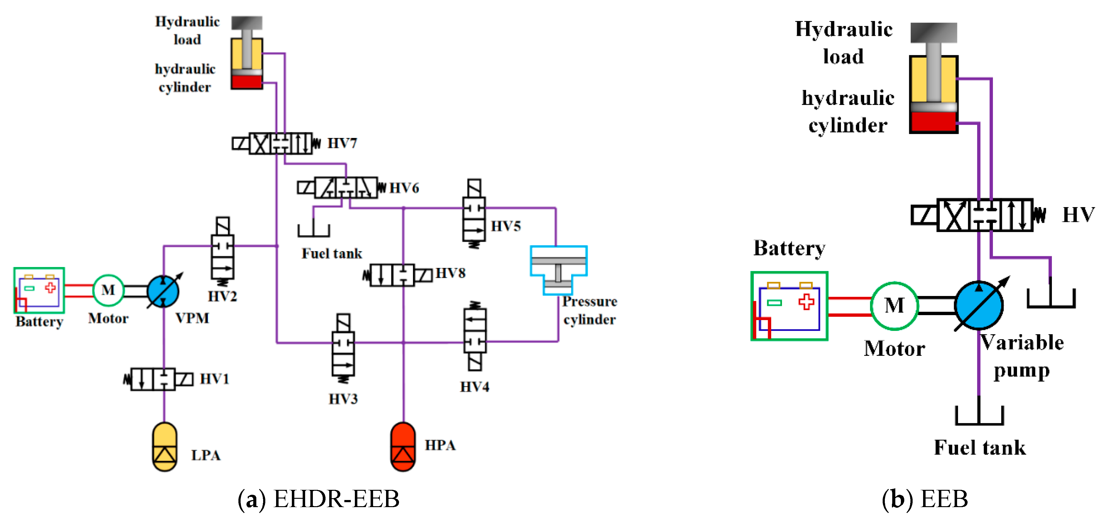
2. Design of the EHDR-EEB

2.1. Structure of the EHDR-EEB

A specific electro-hydraulic drive and energy recovery system of an electric excavator boom is shown in Figure 1. The system includes the battery, motor, variable hydraulic pump/motor (VPM), high-pressure accumulator (HPA), low-pressure accumulator (LPA), hydraulic cylinder, pressure cylinder, hydraulic valves(HV) and other components. The VPM is installed between the motor and the LPA to complete the conversion between hydraulic and mechanical energy. The HPA is connected with the VPM, pressure cylinder and hydraulic cylinder through multiple hydraulic valves. The HPA can supply energy to the hydraulic cylinder to realize its lifting function.
When the boom is lifting, the battery can be used as the power source alone. The electrical energy is converted into mechanical energy by the motor to drive the VPM. Then, the VPM is used as a pump, and the oil is sucked from the LPA and sent to the rodless cavity of the hydraulic cylinder by pressurization, so as to overcome the load and complete lifting. Simultaneously, HPA can be connected directly to the rodless cavity of the hydraulic cylinder, which greatly saves battery power consumption. The gravitational potential energy of the load can be converted into electrical energy and stored in the battery when falling is in progress. It can also recover the hydraulic potential energy without conversion by the HPA. The main function of the LPA is to replenish oil for the HPA. If the LPA pressure is low and the HPA pressure is sufficient, the HPA recharges the LPA. When the HPA pressure is insufficient, the battery can use the motor and VPM to directly charge the HPA to meet the subsequent power requirements of the vehicle.

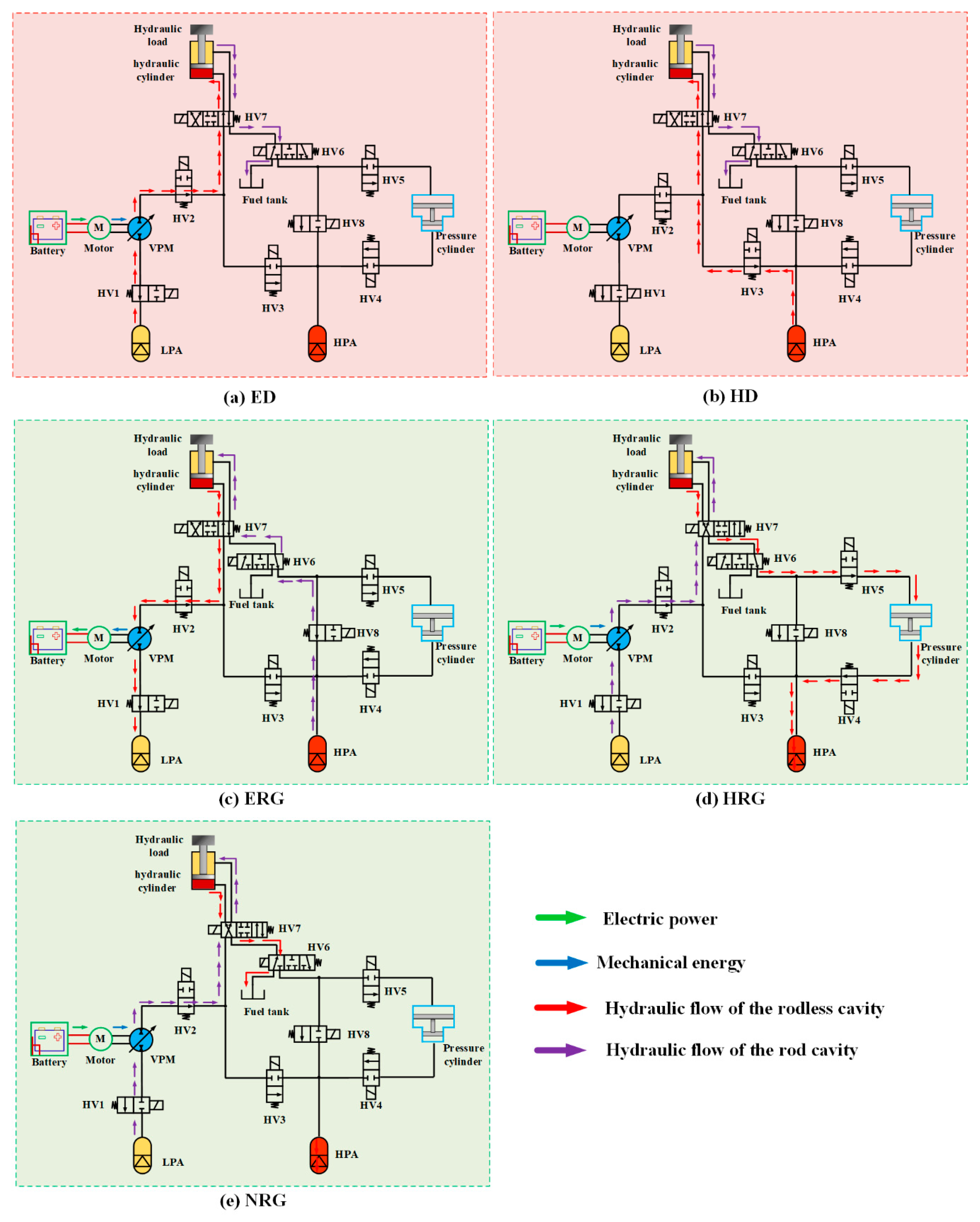
2.2. Principle and Modes of the EHDR-EEB

According to the system structure and the working characteristics of the hydraulic excavator, the system working mode is divided into five modes (Figure 2):
(1)
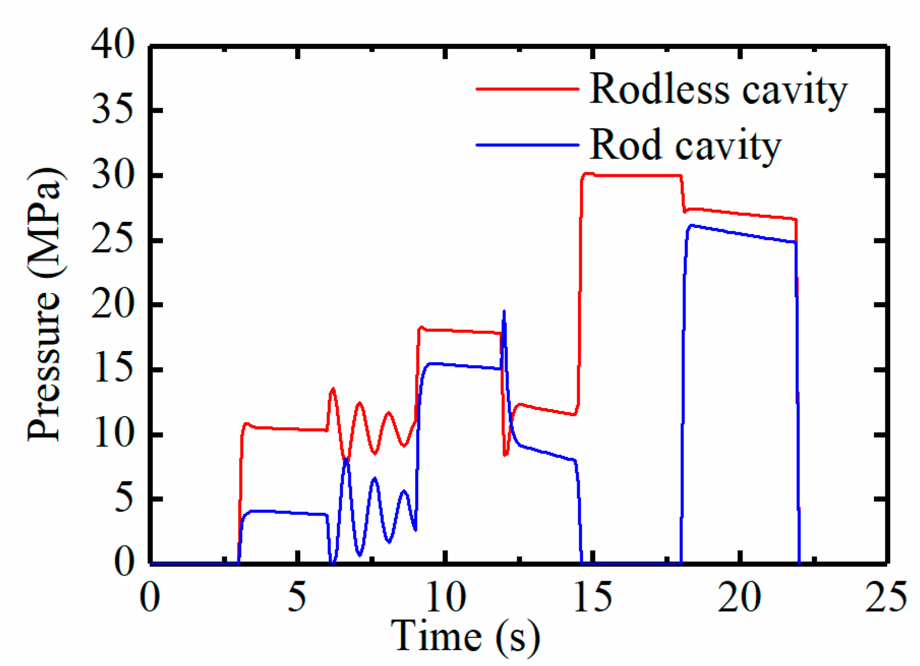
Electrodynamic drive (ED). In this mode, HV1 and HV2 are open, HV7 is in the right position, and HV6 is in the left position. When the motor works, electrical energy is transformed into hydraulic energy through the battery, motor, and VPM. In this case, the VPM is used as a pump, and the low-pressure oil is sucked from the LPA, then transported to the rodless cavity of the hydraulic cylinder through HV2 and HV7. Finally, the hydraulic cylinder piston overcomes the load gravity under the action of pressure and lifts upward. The oil in the rod cavity of the hydraulic cylinder flows back to the fuel tank through HV7 and HV6.
(2)
Hydrodynamic drive (HD). At this time, HV3 is open, HV7 is in the right state, and HV6 is in the left state. The hydraulic oil is delivered from HPA to the rodless cavity of the hydraulic cylinder through HV3 and HV7. The hydraulic cylinder piston lifts upward as described above. The oil in the rod cavity of the hydraulic cylinder flows back to the tank through HV7 and HV6.
(3)
Electric regeneration (ERG). During the load falling process, the battery can recover electrical energy relying on the potential energy of the boom. HV1, HV2, HV8 are in the open state, HV7 is in the right position, and HV6 is in the right position. The piston in the hydraulic cylinder descends under the action of boom gravity and the HPA, and pushes the oil in the rodless cavity into the LPA through HV7 and HV2. Meanwhile, the VPM is used as a motor, which converts hydraulic energy into mechanical energy and drives the motor to work. Afterwards, the motor is used as a generator to output negative torque, convert mechanical energy into electrical energy and store it in the battery.
(4)
Hydraulic regeneration (HRG). When the boom falls, the HPA can recover potential hydraulic energy under the gravity of the boom. Now, HV1, HV2, HV4, and HV5 are open, HV7 is in the left state, and HV6 is in the right state. The piston in the hydraulic cylinder descends with the help of the boom gravity and the VPM, and pushes the oil in the rodless cavity into the HPA through HV7, HV6, HV5, the pressure cylinder and HV4. In this case, the hydraulic energy directly charges the HPA without conversion.
(5)
No regeneration (NRG). If the battery SOC and the HPA pressure are greater than the set threshold in the falling process, HV2 is turned on, and HV7 and HV6 are in the left position. The piston of the hydraulic cylinder descends. The hydraulic oil enters the rod cavity of the hydraulic cylinder through the LPA, VPM and HV2, while the oil in the rodless cavity enters the fuel tank through HV7 and HV6.

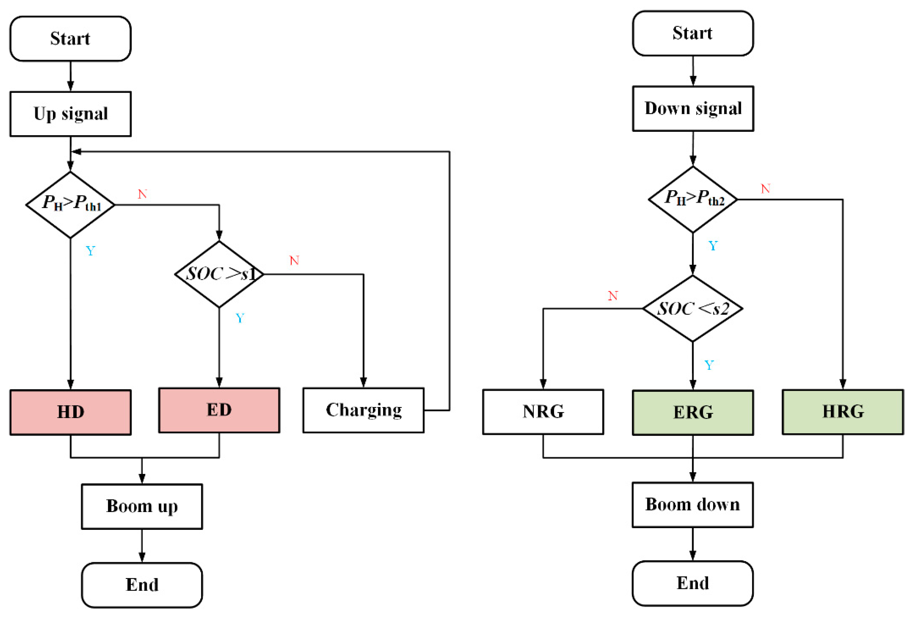
3. Energy Management Strategy Design

This section establishes mathematical modeling of working components: the battery, motor, accumulator and VPM. Subsequently, for excavators equipped with EHDR-EEB, the precise division of the modes and rational design of energy management strategy play an important role in this paper. On this basis, a rule-based energy management strategy is designed, and each operating mode is analyzed.

3.1. Mathematical Modeling

3.1.1. Battery Model

For electric excavators, the battery is the main energy source for the vehicle. The maximum power of the designed battery must meet the maximum power demand of the motor [24]. Meanwhile, the capacity of the battery must meet the needs of the excavator’s work equipment and driving needs. Lithium-ion batteries have high specific energy, high specific power density, a long cycle life and superior comprehensive performance [25]. Therefore, this paper adopts lithium-ion battery as the battery.
(1)
Battery energy
The battery energy is a measure of the battery’s external working ability (kWh), and its stored energy can be expressed as:
E p = V bar C r / 1000
where Vbar is the battery rated terminal voltage, (V), and Cr is the battery rated capacity, (Ah).
(2)
Battery power
In order to meet the power demand of the excavator, the peak power of the battery needs to meet the peak power of the motor.
U t = E o R i
Ut is the battery terminal voltage (V), Eo is the battery electromotive force (V), R is the battery internal resistance (Ω), and i is the discharge current (A).
Then the battery discharge power Pt is:
P t = E o i R i 2
Then the battery theoretical maximum value of the instantaneous power Pmax can be expressed as:
P max = E o 2 4 R
Under actual discharge conditions, the following formula is generally used as the power constraint condition of the battery in engineering applications:
P max P mp η
where Pmp is the motor peak power (kW), and η is the motor efficiency.
SOC represents the charge state of the battery and is an indicator to measure the degree of battery discharge. The SOC state equation is as follows:
S O C ( t ) = S O C 0 0 t i ( t ) d t Q 0
where SOC0 is the initial SOC of the battery (%), and Q0 is the total battery capacity of the battery (mAh).

3.1.2. Motor Model

A permanent magnet synchronous motor is selected for the system. The motor can provide additional peak drive torque or absorb excess boom potential energy. The output mechanical energy of the motor provides rotational kinetic energy for the hydraulic pump/motor. Therefore, the rated power of the motor is the same as that of the hydraulic pump/motor. The motor is coaxially connected to the hydraulic pump/motor, so the speed is consistent. The external load of the boom acts on the rod cavity of the hydraulic cylinder. In the working process of the boom, the rated torque of the motor can be approximated to the average torque of the external load:
P m = 2 π n m 60 t 1 t 2 T load - max d t t 2 t 1
where Pm is the motor rated power, nm is the motor rated speed, and Tload-max is the maximum value of external load demand torque.

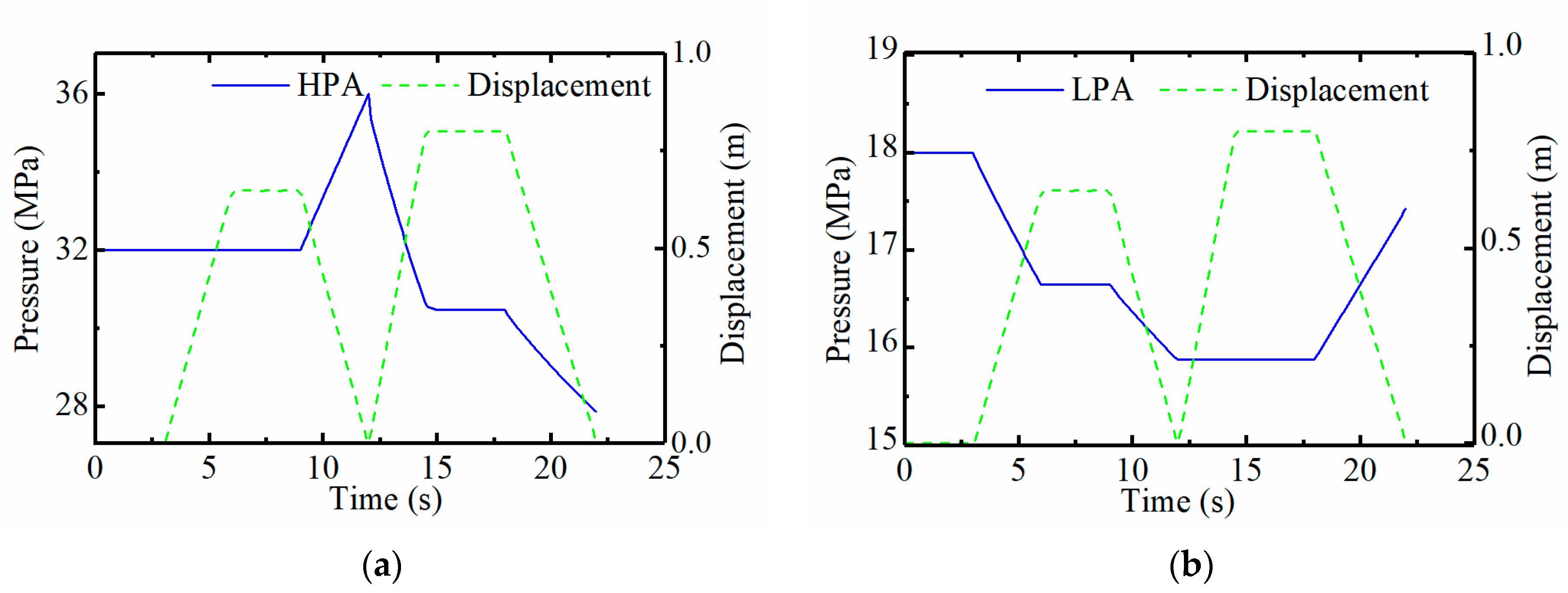
3.1.3. Accumulator Model

The accumulator is a critical component of the hybrid power system. Its parameters include the working pressure, inflation pressure, and accumulator volume, which determine the amount of energy recovery and auxiliary driving energy of the hydraulic regeneration system.
(1)
Working pressure of accumulator
The pressure release and energy storage process of the accumulator can be regarded as an adiabatic process. The gas state equation must be satisfied during the storage and release of energy:
p 0 V 0 n = p 1 V 1 n = p 2 V 2 n
where p0 is the initial working pressure of the accumulator (Pa), V0 is the initial volume of the accumulator (L), V1 is the gas volume when the accumulator pressure is p1 (L), V2 is the gas volume when the accumulator pressure is p2 (L), and n is the gas variability index, assumed to be 1 during the isothermal process, and 1.4 during the adiabatic process.
The higher the maximum working pressure of the accumulator, the more energy can be recovered by the regenerative energy. To ensure as much energy recovery as possible with the accumulator, the minimum working pressure of the accumulator should not be too low. According to the empirical formula [26]:
p min = ( 0.6 0.85 ) p max
the relationship between the accumulator’s lowest pressure pmin and highest pressure pmax can be obtained.
(2)
Inflation pressure
Theoretically, the inflation pressure p0 of the accumulator should be equal to the minimum working pressure. Still, due to the leakage and charging temperature in the process of energy absorption by the accumulator, the inflation pressure should be less than the minimum working pressure. According to the empirical formula [27], the inflation pressure can be calculated as:
p 0 = ( 0.8 0.85 ) p min
(3)
The maximum recovery energy and volume of the accumulator
During the HRG process, the volume of the hydraulic accumulator should be able to recover at least the potential energy under medium load, and the upper limit should be set according to the maximum load energy recovered [28]. The maximum energy that the accumulator can recover is expressed as follows:
E reg = V 0 V 1 p d V = V 0 V 1 p 0 ( V 0 V 1 ) d V = p 0 V 0 n 1 [ ( p 1 p 0 ) n 1 n 1 ]
From the above formula, the initial volume of the accumulator is:
V 0 = ( n 1 ) E reg p 0 [ ( p 1 p 0 ) n 1 n 1 ]
In this formula, Ereg is the maximum energy recovered by the accumulator, and V0 is the initial accumulator volume under the inflation pressure, which can be approximately equal to the volume of the accumulator.

3.1.4. Variable Hydraulic Pump/Motor (VPM)

For the bidirectional variable displacement piston pump, the closed volume at the bottom of the plunger will complete the oil suction and discharge for each rotation when the cylinder swings. The instantaneous flow rate of the pump/motor is expressed as follows:
Q i = π d 2 4 w R tan α sin φ
where d is the plunger diameter, R is the distribution circle radius of the plunger axis in the cylinder, w is the rotational angular velocity of cylinder, α is the swashplate inclination, and φ is the plunger angle.
The VPM is mainly selected in terms of the displacement parameters. During the lifting process, it is used as a motor to output mechanical torque or as a pump in the hydraulic recovery process. The input torque is expressed as follows:
T p = β V Δ p 20 π
where Tp is the input torque of the secondary component (Nm), β is the opening of the secondary element swash plate (−1, 1), V is the secondary component displacement (mL/r), and Δ p is the working pressure of the secondary element (MPa). The efficiency of the secondary element is regarded as 1.

3.2. Rule-Based Energy Management Strategy

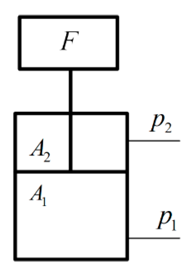
3.2.1. Mechanical Model of the Hydraulic Cylinder in Boom

Aiming at the recovery process of gravitational potential energy when the boom is descending, the mechanical model (Figure 3) of the boom hydraulic cylinder is analyzed [29] according to Equation (15):
p 2 A 2 + F = p 1 A 1 + b x + M x + F f
where p2 is the cylinder pressure of rod cavity, A2 is the effective area of the rod cavity, p1 is the cylinder pressure of the rodless cavity, A1 is the effective area of the rodless cavity, b is the viscous damping on the piston and load, x′ is the piston movement speed, x″ is the piston acceleration, M is the equivalent mass of the piston and load, and Ff is the friction between the hydraulic cylinder and piston.

3.2.2. Demand Flow

The driver operates the joystick to give control commands to the boom [30]. In this paper, the boom is selected to run at a constant speed when it rises and falls.
v req = α v max
vmax is the maximum speed of the boom cylinder, α is the joystick signal, [0, 1], and vreq is the required speed of the boom cylinder.
q req = v req A c
qreq is the required flow of the boom cylinder, and Ac is the piston area of the boom cylinder.
P req = p c q req
Preq is the demand power of the boom cylinder, and pc is the cylinder pressure of rodless cavity.

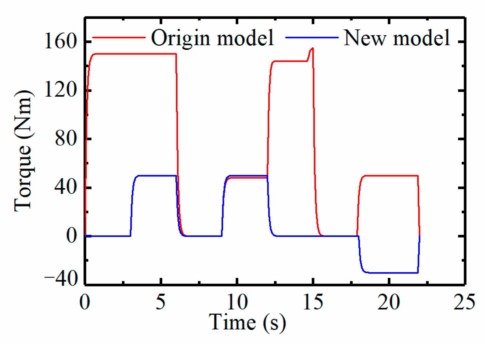
3.2.3. Demand Power and Torque of the Motor

(1)
ED
In this mode, all required power is provided by the motor when cylinder is lifting. The power and torque of the motor are expressed as follows:
P mq = P req η P
T mq = 9550 P mq n m
where Pmq is the motor’s required power, ηP is the motor’s efficiency, Tmq is the motor’s required torque, and nm is the motor’s speed.
(2)
HD
In this mode, the motor does not participate in driving, so the motor power and torque are both 0.
(3)
ERG
When the boom descends, the gravitational potential energy is converted to electrical energy and stored in the battery, rather than to hydraulic energy stored in the HPA. Meanwhile, the motor is used as a generator.
T mq = V P Δ p β 20 π
β is the opening of the secondary element swash plate (−1, 1), VP is the secondary component displacement (mL/r), and Δ p is the working pressure of the secondary element (MPa).
(4)
HRG
In this mode, the gravitational potential energy is converted into hydraulic energy and stored in the HPA rather than in the battery when the boom descends. The motor still provides a certain amount of power for the hydraulic cylinder, setting to be 1/5 of the weight of the hydraulic cylinder, where G is the weight of the cylinder.
P req = G Δ x 5 Δ t
T mq = 9550 P req n m η p
(5)
NRG
This working condition generally occurs when the SOC and the pressure of the HPA reach the maximum setting threshold, and there is no energy recovery when the hydraulic cylinder falls. The motor still provides a certain amount of power with the help of the hydraulic cylinder’s own weight to lower the boom. Similarly, the power provided is still 1/5 of the self-weight of the hydraulic cylinder. The power and torque required by the motor are the same as the HRG working conditions.

3.2.4. Energy Management Flowchart

Figure 4 shows the control strategy for the lifting and lowering conditions of the boom system, and the strategy can be explained as follows:
Boom lifting process: the boom cylinder sensor receives a driver-operated up signal. First, the HPA determines whether PH is greater than Pth1. If PH > Pth1, the system enters HD mode and completes the boom lifting condition. If PHPth1, it is judged to be the SOC threshold. If SOC > s1, the system enters the ED mode to complete the boom lifting condition. If SOC ≤ s1, the system enters the battery charging mode.
Boom lowering process: the boom cylinder sensor receives a driver-operated descent signal. The HPA judges whether PH is greater than Pth2. If PH > Pth2 and SOC < s2, the system enters the ERG mode to initiate regenerative braking, and converts the gravitational potential energy of the boom into electrical energy, then recycles it into the battery to complete the lowering condition. If PHPth2, the system enters the HRG mode, converts the gravitational potential energy of the boom into hydraulic energy and stores it in the HPA. If PH > Pth2, and SOC ≥ s2, there is no potential energy recovery when boom is lowering.

4. Simulation Analysis

4.1. Component Selection

The paper examines the recovery of the boom potential energy of an electro-hydraulic excavator during the movement process of the traditional excavator boom, and carries out the recovery and utilization of the boom potential energy. Based on the basic problems existing in the potential energy regeneration system of small hydraulic excavator booms, the design scheme adopted in this paper is as follows. Firstly, the original battery of the electric excavator is used to recover the gravity potential energy of the boom. Secondly, accumulators with high power density are used as auxiliary energy storage elements. The excavator boom system not only has the function of the original excavator boom, but also recycles the potential energy of the boom as much as possible to improve the economy without affecting the operability. Table 1 shows the parameter settings of the small electro-hydraulic excavator. The parameters of the accumulator and hydraulic pump/motor need to be redesigned, while the remaining components remain the same as the original excavator.

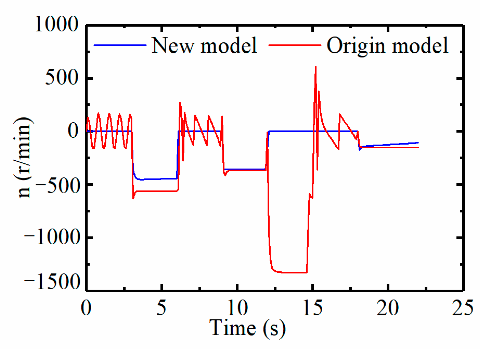
4.2. Analysis of Boom Motion Characteristics
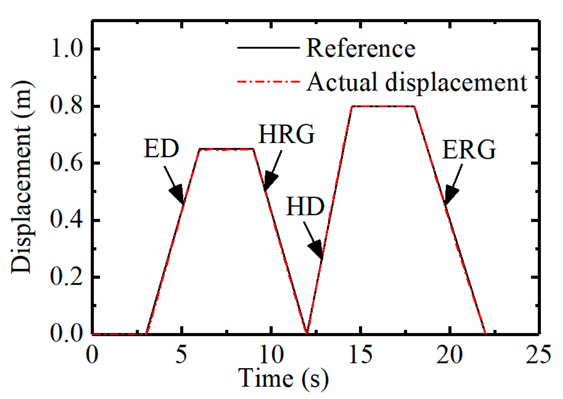
Figure 5 shows the single-cycle trajectory of the piston in the hydraulic cylinder. The boom full load test is the research object, and the test period is 22 s. To ensure the standardization of the research, the assumptions are as follows:
(1)
The reference curve is the motion characteristics of the original boom system, and the actual displacement curve is the EHDR-EEB motion characteristics. The purpose is to compare the EHDR-EEB with the original system and make the new system as close as possible to the kinematic characteristics of the original boom system.
(2)
Test cycle time setting: the boom piston starts to move from 3 s; it takes about 3 s to rise to 0.65 m, stays for 3 s, and then descends to the lowest position. After that, it rises to the highest position 0.8 m for 3 s, and stays at the highest position for 3 s. Finally, it takes about 4 s to drop to the lowest position. The test cycle and the movement trajectory of the boom piston are shown in Figure 5.
(3)
The position setting of the boom cylinder piston: the piston stops at the maximum position 0.8 m. and the middle position is at about 0.65 M.
(4)
During lifting process, it is assumed that the external load remains unchanged. In the falling process, the unloading work has been completed, and the load is zero.

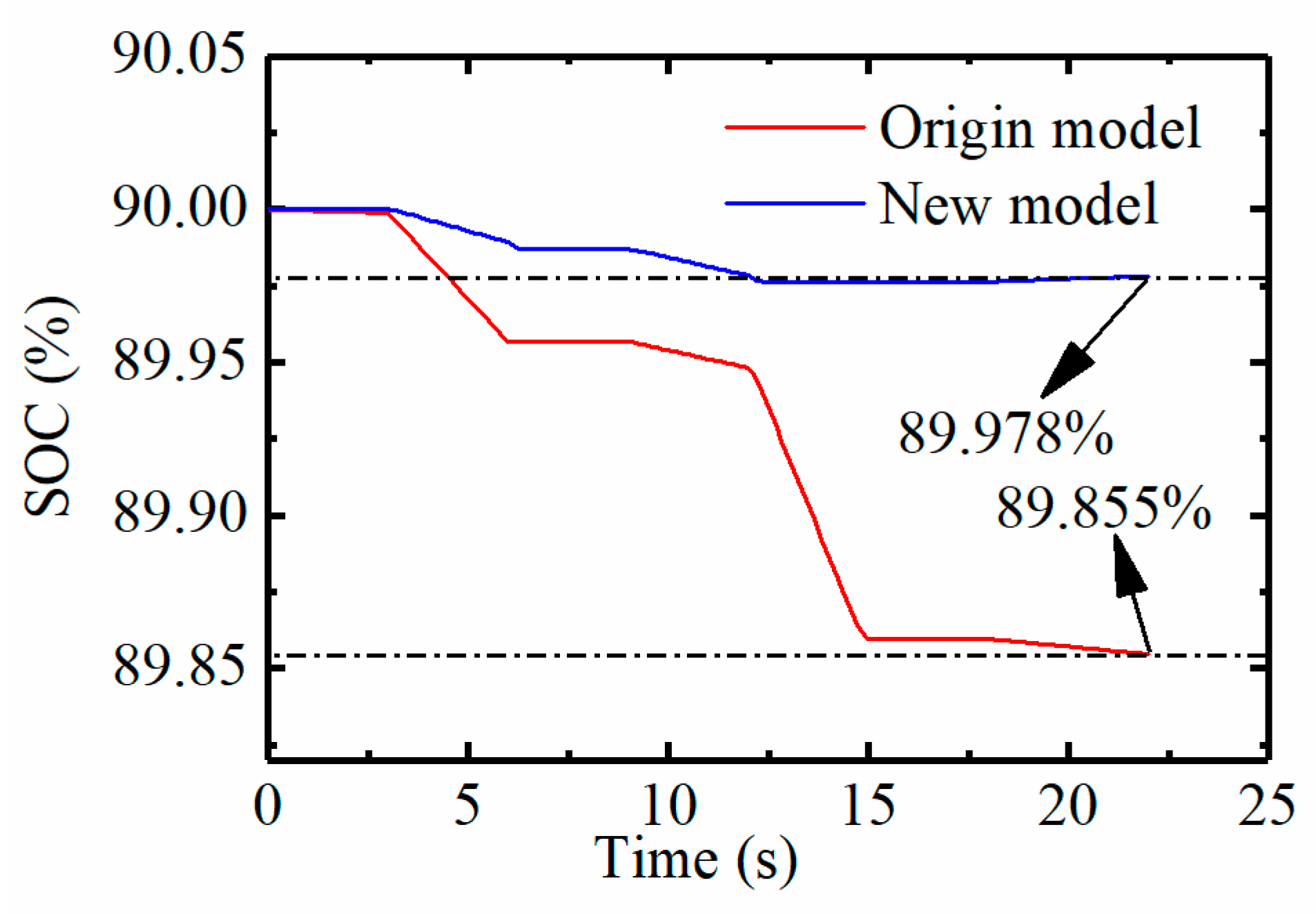
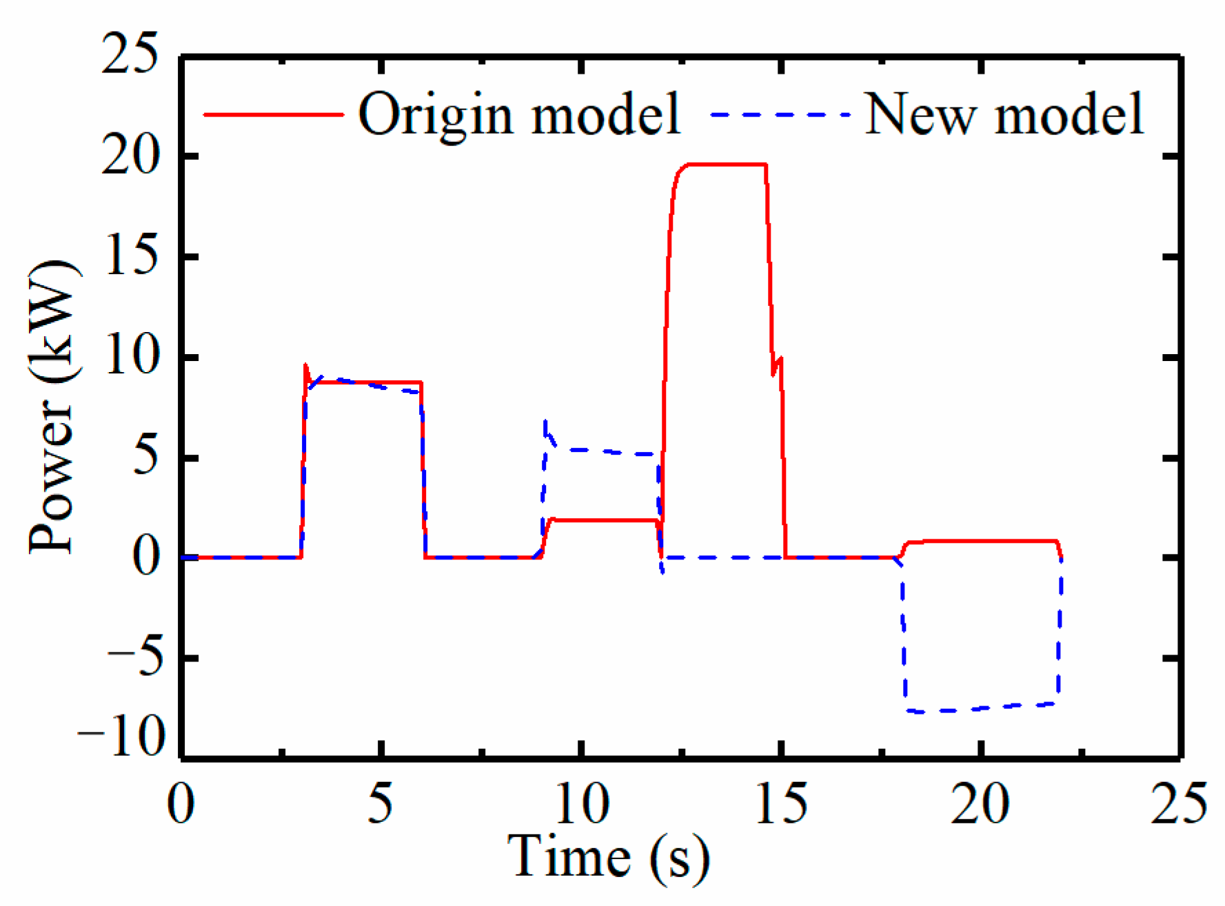
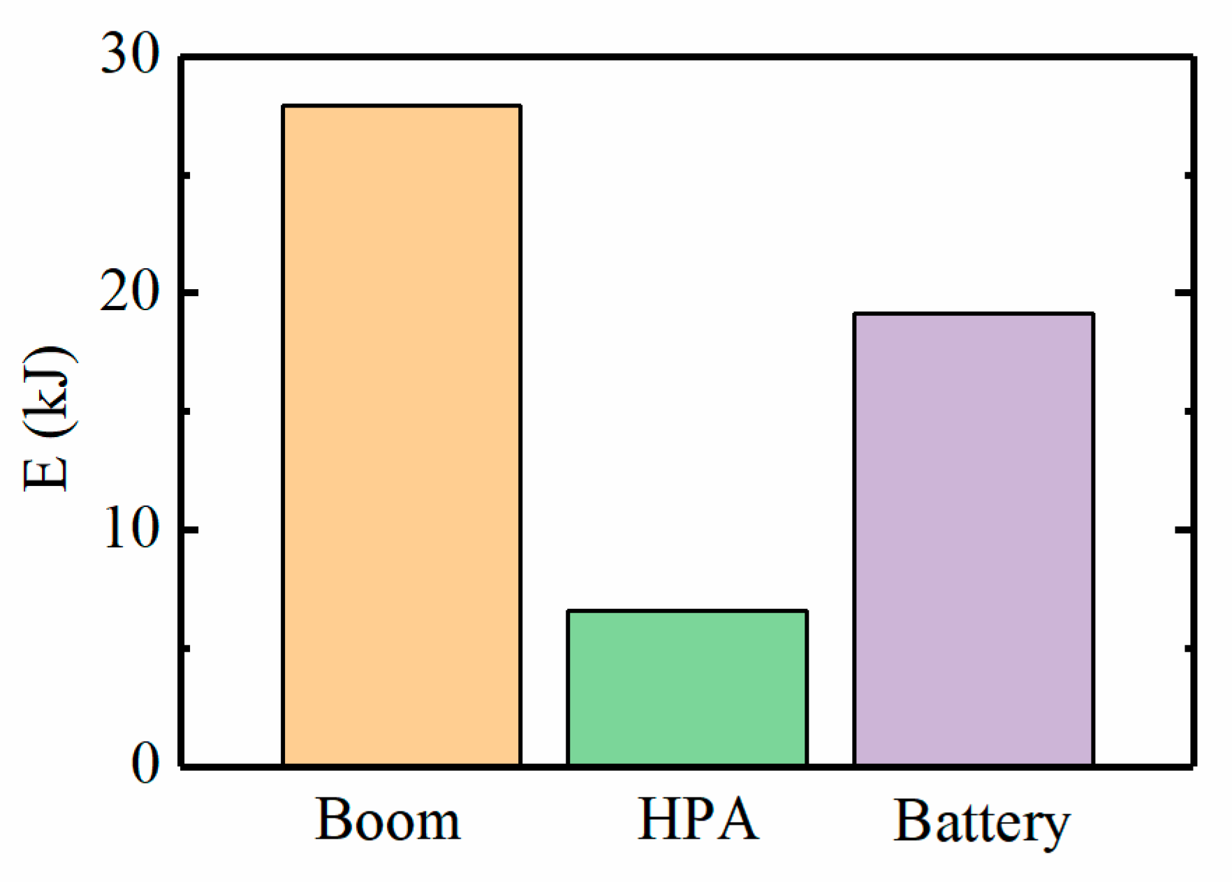
4.3. Operating Energy Consumption Analysis

In this paper, the pressure changes in the rod cavity and the rodless cavity are analyzed in Figure 6. The results illustrate that in the ED stage, the oil pressure in the rodless cavity is about 10 MPa, and the oil pressure in the rod cavity is 4.7 MPa. At this time, the motor drives the VPM to work, and pressurizes the hydraulic oil in the LPA into the rodless cavity of the cylinder to push the piston to move upward and lift the goods against the load gravity. When in balance, the oil in the two chambers remains stationary, but fluctuates slightly. In the HRG stage, the VPM assists in supplying hydraulic oil under the force of the piston and boom. Then the oil in the rodless cavity flows back to the HPA to charge the HPA, which is pressurized by the pressure cylinder. In the HD stage, the HPA supplies oil to the rodless cavity of the hydraulic cylinder. When the piston is in the highest position, the load is unloaded, and the load force suddenly decreases. Therefore, the pressure in the rod cavity drops to 0 in the balance stage of the highest position, and the pressure in the rodless cavity increases to 30 MPa. In the ERG stage, under the action of the HPA, the oil in rod cavity pushes the piston down together with the help of the boom. Accordingly, the pressure in the rodless cavity increases, and the oil enters the LPA under the action of the VPM. In this process, the hydraulic energy is converted into mechanical energy to drive the motor. The motor is used as a generator, and the potential energy of the boom is converted into electrical energy and stored in the battery.
The pressure curves of the accumulators are shown in Figure 7. The initial pressure of the LPA is 18 MPa, and the initial pressure of the HPA is 32 MPa. In the ED stage, the HPA does not participate in the job, the pressure remains unchanged, and the LPA pumps the oil into the rodless cavity of the hydraulic cylinder by the VPM so the LPA pressure drops. In the HRG stage, the boom potential energy is converted into hydraulic energy stored in the HPA, and the HPA pressure rises to 36 MPa. The LPA participates in this stage, so the LPA pressure drops to 15.8 MPa. In the HD stage, the HPA releases energy to move the piston up, which leads to a pressure drop to 30.2 MPa. The LPA does not work so the pressure remains unchanged. In the ERG stage, the gravitational potential energy of the boom is converted into electrical energy. During this process, the oil in the rodless cavity flows into the LPA through the VPM, and the pressure in the LPA rises to 17.5 MPa. Simultaneously, the HPA assists the boom to move down, and the output hydraulic oil enters the rod cavity. After that, the pressure in the HPA drops to 28 MPa.
From the torque curves of the motor in Figure 8, the following conclusions can be drawn: In the original model (EEB), the motor is only used as a motor which cannot recover energy, and the maximum torque is 150 Nm. In the new model (EHDR-EEB), the motor acts as a motor in the ED, HRG and ERG stages, and outputs positive torque with a maximum torque of 50 Nm. Moreover, in the ERG stage, it is used as a generator to output a negative torque of −30 Nm, convert the kinetic energy transmitted by the motor into electrical energy and store this energy in the battery.
As can be seen in Figure 9, the motor in the original model has jitter problems, and the maximum speed is 1300 r/min, far exceeding the maximum speed of the motor in the new model. Fluctuation occurs when the motor torque suddenly increases from zero to a peak value or drops rapidly to zero in the origin model. The process of changing the speed of the motor from one point to another takes time, and there is a time delay. However, the working time of the boom is short, which results in the phenomenon of rotational speed fluctuation. In the EHDR-EEB, the motor does not work and the speed is zero from 0 to 3 s. The system enters the HRG stage at 9 s. Although the motor participates in work, the variation range of peak torque is very small, and its peak torque is one third that of the original model motor, so it cannot cause fluctuation in speed. Therefore, the new system can compensate the motor speed and torque through the accumulator, eliminate the jitter phenomenon, and reduce the large peak torque during the frequent operation of the motor.
According to the battery SOC curve, it can be seen that the new system has a more obvious energy-saving effect than the original system, and the SOC has increased in Figure 10. As seen in in Figure 11, the maximum power of the VPM in the original model is 19.8 kW, whereas that in the new model is 9 kW. In the ERG stage, the VPM in the new model is used as a motor, producing −8.6 kW to convert the hydraulic energy into electrical energy stored in the battery.
Figure 12 represents the distribution of the recovered energy diagram. The boom descends twice during a 22 s period, and its gravitational potential energy is 27,925 J. The hydraulic energy recovered by the HPA is 6579 J in the HRG stage. The energy recovered by the battery is 19,125 J and is converted from hydraulic energy by the VPM and motor in the ERG stage. According to calculations, 92% of the potential energy of the boom can be recovered during the lowering process.

5. Conclusions

In this paper, a novel electro-hydraulic drive and energy recovery system for the electric excavator boom is proposed. Based on the simulation, the displacement curve of the boom cylinder piston, the pressure curve of the hydraulic cylinder and the accumulator, the motor speed and torque curve, the SOC curve, the VPM power curve, and the recovered energy distribution curve are analyzed in detail during the lowering process. Compared with the original electric excavator, the new system has achieved significant energy savings in the four working modes ED, HD, HRG and EGR. The results show that the potential energy recovery rate is 92%. Most potential energy is stored in the battery by means of electrical energy. In addition, the maximum torque of the motor in the new system is reduced by 66.7% compared with the original system, which greatly reduces the large peak torque when the motor starts and stops frequently, stabilizes the motor speed, and eliminates the motor’s chattering problem. This technology provides ideas for the direction of future research and development of energy recovery in electric excavators and a fundamental reference for improvements in the recovery and utilization of boom potential energy.

Author Contributions

Conceptualization, L.L. (Lin Li); methodology, T.Z. and L.L. (Lin Li); validation, T.Z., K.W. and L.L. (Liqun Lu); data curation, L.L. (Lianhua Lin) and H.X.; writing—original draft preparation, L.L. (Lin Li); writing—review and editing, L.L. (Lin Li) and T.Z.; funding acquisition, T.Z. All authors have read and agreed to the published version of the manuscript.

Funding

This research was funded by the International Technology Cooperation projects (No. 2019GHZ016), Innovation Team Project of “Youth Innovation Technology Program” of Shandong Higher Education Institution (No. 2021KJ083), Major science and technology innovation project of Shandong Province of China (No. 20020CXGC010405).

Institutional Review Board Statement

Not applicable.

Informed Consent Statement

Not applicable.

Data Availability Statement

Not applicable.

Conflicts of Interest

The authors declare that they have no known competing financial interest or personal relationships that could have influenced the work reported in this paper.

Nomenclature

EHDR-EEBElectro-hydraulic drive and energy recovery system of the electric Excavator Boom
EEBElectric excavator boom
VPMVariable hydraulic pump/motor
HPAHigh pressure accumulator
LPALow pressure accumulator
EDElectrodynamic drive
HDHydrodynamic drive
ERGElectric regeneration
HRGHydraulic regeneration
NRGNo regeneration
SOCState of charge

References

  1. Vacca, A. Energy efficiency and controllability of fluid power systems. Energies 2018, 11, 1169. [Google Scholar] [CrossRef] [Green Version]
  2. Ding, R.; Zhang, J.; Xu, B.; Cheng, M.; Pan, M. Energy efficiency improvement of heavy-load mobile hydraulic manipulator with electronically tunable operating modes. Energy Convers Manag. 2019, 188, 447–461. [Google Scholar] [CrossRef]
  3. Wu, W. Study on Energy-Saving and Power Matching of Parallel-Hybrid Hydraulic Excavator. Ph.D. Thesis, Southwest Jiaotong University, Chengdu, China, 2015. [Google Scholar]
  4. Chen, M.; Zhao, D. The gravitational potential energy regeneration system with closed-circuit of boom of hydraulic excavator. Mech. Syst. Signal Process. 2017, 82, 178–192. [Google Scholar] [CrossRef]
  5. Yu, Y.-X.; Ahn, K.K. Energy regeneration and reuse of excavator swing system with hydraulic accumulator. Int. J. Precis. Eng. Manuf. Green Technol. 2020, 7, 859–873. [Google Scholar] [CrossRef]
  6. Li, J.; Ding, H.; Zhao, J.; Qin, J.; Shi, J.; Wang, Z. Design and simulation analysis of hybrid boom potential energy recovery system for super large hydraulic excavator. Chin. Hydraul. Pneum. 2019, 7, 33–38. [Google Scholar]
  7. Fu, C.; Zou, G. Boom Potential Energy Recovery of Hydraulic Excavator Working Mechanism. J. Univ. Jinan (Sci. Technol.) 2018, 32, 4. [Google Scholar]
  8. Ye, Y.; Lin, T.; Ren, H. Research on the potential energy regeneration and utilization in hydraulic based on balance cylinder. Chin. Hydraul. Pneum. 2018, 1, 71–77. [Google Scholar]
  9. Lin, Y.; Lin, T.; Chen, Q.; Li, Z.; Fu, S.; Ren, H.; Guo, T. Research progress on key technologies of electric construction machinery. Chin. Hydraul. Pneum. 2021, 45, 1. [Google Scholar]
  10. Casoli, P.; Ricco, L.; Campanini, F.; Bedotti, A. Hydraulic hybrid excavator—Mathematical model validation and energy analysis. Energies 2016, 9, 1002. [Google Scholar] [CrossRef] [Green Version]
  11. Hao, L.; Fu, K.; Yu, B.; Lou, W.; Ma, G.; Qin, H. Reliability analysis of an incremental digital valve. Chin. Hydraul. Pneum. 2020, 48, 168–171. [Google Scholar]
  12. Yi, H.; Cha, S. Optimal energy management of the electric excavator using super capacitor. Int. J. Precis. Eng. Manuf. Green Technol. 2019, 8, 151–164. [Google Scholar] [CrossRef]
  13. Wang, T.; Wang, Q. Efficiency analysis and evaluation of energy-saving pressure compensated circuit for hybrid hydraulic excavator. Autom. Constr. 2014, 47, 62–68. [Google Scholar] [CrossRef]
  14. Xia, L.; Quan, L.; Ge, L.; Hao, Y. Energy efficiency analysis of integrated drive and energy recuperation system for hydraulic excavator boom. Energy Convers. Manag. 2018, 156, 680–687. [Google Scholar] [CrossRef]
  15. Zhang, Y. Research on Energy Saving for Hydraulic Excavators Based on Hybrid and Regeneration. Ph.D. Thesis, Zhejiang University, Hangzhou, China, 2006; pp. 27–32. [Google Scholar]
  16. Yuan, X.; Wu, J. Research on the development of pure electric vehicle power battery technology based on patent analysis. In Proceedings of the IOP Conference Series: Earth and Environmental Science, Changsha, China, 18–20 September 2020; Volume 615, p. 012081. [Google Scholar]
  17. Yang, Z.; Ravey, A.; Marion-P’era, M.C. Multi-objective energy management for fuel cell electric vehicles using online-learning enhanced Markov speed predictor. Energy Convers Manag. 2020, 213, 112821. [Google Scholar]
  18. Parikh, D.; Christensen, T.; Li, J. Correlating the influence of porosity, tortuosity, and mass loading on the energy density of LiNi0.6Mn0.2Co0.2O2 cathodes under extreme fast charging (XFC) conditions. J. Power Sources 2020, 474, 228601. [Google Scholar] [CrossRef]
  19. Chen, M.; Zhao, D. Research on recoverable potential of hydraulic excavator. Mach. Tool Hydraul. 2016, 44, 65–68. [Google Scholar]
  20. Gong, J.; Zhang, D.; Liu, C.; Zhao, Y.; Hu, P. Power control strategy and performance evaluation of a novel electro-hydraulic energy-saving system. Appl. Energy 2019, 233, 724–734. [Google Scholar] [CrossRef]
  21. Chen, Z.; Fu, J.; Zhang, X.; Cheng, H.; Quan, L. Electro-hydraulic recovery system of swing braking energy in hydraulic excavator. Mach. Tool Hydraul. 2018, 46, 1–8. [Google Scholar]
  22. Yao, M.; Wu, W.; Qin, J.; Sun, L. Study on energy recovery system for electro-hydraulic coordinated hydraulic excavator Compound action. Mach. Tool Hydraul. 2018, 46, 54–59. [Google Scholar]
  23. Lin, T.; Wang, Q.; Hu, B.; Gong, W. Research on the energy regeneration systems for hybrid hydraulic excavators. Autom. Constr. 2010, 19, 1016–1026. [Google Scholar] [CrossRef]
  24. Hong, J.; Wang, Z.; Ma, F.; Yang, J.; Xu, X.; Qu, C.; Zhang, J.; Shan, T.; Hou, Y.; Zhou, Y. Thermal runaway prognosis of battery systems using the modified multi-scale entropy in real-world electric vehicles. IEEE Trans. Transp. Electrif. 2021, 7, 2269–2278. [Google Scholar] [CrossRef]
  25. Yang, J.; Zhang, T.; Zhang, H.; Meng, Z. Research on the starting acceleration characteristics of a new mechanical–electric–hydraulic power coupling electric vehicle. Energies 2020, 13, 6279. [Google Scholar] [CrossRef]
  26. Yang, J.; Zhang, T.; Hong, J.; Zhang, H.; Zhao, Q.; Meng, Z. Research on driving control strategy and fuzzy logic optimization of a novel mechatronics-electro-hydraulic power coupling electric vehicle. Energy 2021, 233, 121221. [Google Scholar] [CrossRef]
  27. Hong, J.; Wang, Z.; Chen, W.; Wang, L.; Lin, P.; Qu, C. Online accurate state of health estimation for battery systems on real-world electric vehicles with variable driving conditions considered. J. Clean. Prod. 2021, 294, 125814. [Google Scholar] [CrossRef]
  28. Geng, Y.; Yang, J.; Quan, L. Power matching of hybrid excavator based on load balance. Chin. Hydraul. Pneum. 2017, 2, 63–69. [Google Scholar]
  29. Altare, G.; Vacca, A. A design solution for efficient and compact electrohydraulic actuators. Procedia Eng. 2015, 106, 8–16. [Google Scholar] [CrossRef] [Green Version]
  30. Shi, J.; Quan, L.; Zhang, X.; Xiong, X. Electro-hydraulic velocity and position control based on independent metering valve control in mobile construction equipment. Autom. Con. Struct. 2018, 94, 73–84. [Google Scholar] [CrossRef]
Figure 1. Structure diagram of the EHDR-EEB and EEB: (a) EHDR-EEB; (b) EEB.
Energies 15 04757 g001
Figure 2. Working principle of the EHDR-EEB: (a) ED; (b) HD; (c) ERG; (d) HRG; (e) NRG.
Energies 15 04757 g002
Figure 3. Mechanical model diagram of the hydraulic cylinder.
Energies 15 04757 g003
Figure 4. Control strategy of the EHDR-EEB. PH: the pressure of HPA, Pth1: the pressure setting threshold when lifting, Pth2: the pressure setting threshold when lowering, s1: the SOC threshold when lifting, s2: the SOC threshold when lowering.
Energies 15 04757 g004
Figure 5. Piston Displacement Curve.
Energies 15 04757 g005
Figure 6. Pressure of the cylinder for the EHDR-EEB.
Energies 15 04757 g006
Figure 7. Pressure of accumulators: (a) HPA; (b) LPA.
Energies 15 04757 g007
Figure 8. The motor torque comparison chart.
Energies 15 04757 g008
Figure 9. The motor speed comparison chart.
Energies 15 04757 g009
Figure 10. Economic verification results: SOC change.
Energies 15 04757 g010
Figure 11. Power curve of the VPM.
Energies 15 04757 g011
Figure 12. Distribution of the recovered energy during boom lowering.
Energies 15 04757 g012
Table 1. Hydraulic components and parameters.
ComponentValueRemark and Unit
Hydraulic cylinder0.055 × 0.03 × 0.8Piston dia. × rod dia. × stroke length (m)
Hydraulic pump/motor20Displacement (mL/r)
Low pressure accumulator12–18Working pressure (MPa)
High pressure accumulator26–38Working pressure (MPa)
Motor10Rated power (kW)
Battery35Maximum power (kW)
Load force50kN
Publisher’s Note: MDPI stays neutral with regard to jurisdictional claims in published maps and institutional affiliations.

