1. Introduction
In Italy, Legislative Decree 22 January 2004, n. 42 governs the ‘
Code of cultural heritage and landscape, according to article 10 of the law of 6 July 2002, no. 137’ [
1]. The Republic protects and enhances cultural heritage under powers referred to in Article 117 of the Constitution and provisions of this Code. Articles 1, 2 and 3 define the principles, cultural heritage and preservation. Preservation and enhancement of cultural heritage preserve the national community’s memory and territory and promote cultural development. The state, regions, metropolitan cities, provinces and municipalities must ensure and support the conservation of cultural heritage and favour public use and enhancement of the built heritage. The activities concerning conservation, use and enhancement of cultural heritage indicated in paragraphs 3, 4 and 5 must comply with legislation. Enhancement is defined as the exercise of functions and in the discipline of activities to promote knowledge of cultural heritage and ensure the best conditions for public use and enjoyment of heritage itself, even by people with disabilities, to promote the development of culture. It also includes the promotion and support of cultural heritage conservation interventions. Concerning the landscape, enhancement also includes the redevelopment of buildings and areas subject to compromised or degraded preservation or creating new coherent and integrated landscape values. Furthermore, Art. 29 identifies the principles and activities relating to conservation. The latter is ensured through coherent, coordinated, planned study and prevention, maintenance and restoration activities. With the regions’ help and the collaboration of competent universities and research institutes, the Ministry defines guidelines, technical standards, criteria, and intervention models in conserving the cultural heritage (CH) field. At a European Level, CH is of exceptional economic importance for the AEC and tourism industries, generating an estimated annual revenue of EUR 335 billion. Many of the 9 million jobs in the tourism sector are linked directly or indirectly. The EU-funded project Cultural Heritage Counts for Europe aims to raise greater awareness of cultural heritage’s social, economic, cultural and environmental impact and the multiple benefits of investing in it [
2]. Communication recognises that the contribution of CH to economic growth and social cohesion is undervalued and examines how the societal value of the section is addressed in current actions and funding programmes. It highlights the opportunities for Member States and stakeholders to work more closely across borders to address the many challenges facing the heritage sector and ensures that CH makes an even more vital contribution to a sustainable Europe. Despite this contribution, policy and strategy documents give little attention to the existing urban areas. Even if the applied research in the digital cultural heritage (DCH) domain is growing [
3,
4,
5], the knowledge available on its challenges and solutions remains limited. In this context, the Appia Antica Archaeological Park and the Politecnico di Milano collaborated to define a process that can support the restoration of the Roman aqueducts in the Tor Fiscale Park. The Appia Antica Archaeological Park was born as an institution with special autonomy (scientific, financial, accounting and administrative) as part of the Franceschini reform of the MIC reorganisation (DM 44/2016, DM 198/2016 and DPCM 169/2019) in which institutes and museums of significant national interest have been identified [
6]. The study described below aims to integrate architectural knowledge of the monument with studies conducted and create multi-temporal digital outputs capable of supporting the decision-making process for conservation and management of the historical asset. The park is one of the articulations of Appia Antica Regional Park and is nestled between Via Appia Nuova and Via Tuscolana, at the level of the Quadraro. Established in 1988 to protect the archaeological complexes and the landscape heritage of a unique territory, the Appia Antica Park now covers an area of 4500 hectares. Its borders have widened over time to include—in addition to the first stretch of the Via Appia Antica—also the Caffarella Park, the Tombs of the Via Latina, the Parco degli Acquedotti, the Tenuta di Tormarancia, the Farnesiana, the areas of Divino Amore, Falcognana, Mugilla and, of course, the Tor Fiscale Park. Today, the tower dominates the landscape characterised by vineyards, vegetable gardens, and large meadows. At the entrance to the park, visitors are immediately transported to a timeless dimension, where the remains of the ancient aqueducts chase each other in the Roman countryside, a few steps from the town. Walking along the archaeological ruins of this Roman infrastructure means getting in touch with the history, culture and ways of life of the past, learning the foundations of the engineering of the time and delighting in the state of conservation of some traits which are truly unique and surprising (
Figure 1). On the other hand, the urgent need to protect, preserve and restore the main sections of the aqueducts has required a massive deployment of methodological tools and innovative research approaches aimed at the multi-scale and multi-temporal digitisation process of the entire park area from the territorial–urban scale to the architectural and archaeological scale of every single section of the aqueduct trying to guarantee the reliability of the data produced in morphological, geometric and informative terms.
As is well known, professionals involved in the preservation process should clearly understand structural behaviour and building construction [
7,
8,
9]. This objective can be achieved through a methodological approach that provides the case study’s geometric, decay, damage, physical and material characteristics [
10,
11,
12]. Structure analysis consists of verifying the degree of safety of a structure against external actions by applying specific theories [
13,
14]. Therefore, it requires HBIM models capable of developing calculations by positioning its constituent elements, specifying the relationships that allow them to behave as a unitary whole. It also implies the knowledge of the basic principles governing solid bodies’ behaviour of different shapes and finite element method (FEM) models subject to the action of systems of forces [
15,
16]. Starting with Galileo and through the contribution of many scholars, researchers and restorers, mathematics and mechanics have gradually become part of the design practice [
17]. The Art of Building and architectural restoration have gradually become a scientific discipline, gradually transforming itself into the Science of Building and a complete fusion of historical and technical-scientific expertise [
18,
19]. Science of Building allows the formulation of mathematical models that support the designer in his choices. Accordingly, by model, we mean a conceptual representation, inevitably simplified, of a physical phenomenon capable of explaining its functioning by resorting to a mathematical formulation. The designer uses experimental or abstract models to predict and control the behaviour of a structural system before the construction process is started, as (i) a model for the geometric scheme of the structure and its constituent elements, (ii) a model for the schematisation of the constraints, (iii) a model of the mechanical behaviour of materials (constitutive bonds), (iv) a model for the definition of the acting actions, and finally (v) the model for the evaluation of stresses which together constitute the so-called calculation [
9,
20]. The modern structural design approach verifies a structural system through numerical calculations. Calculations are based on a mathematical model describing the system’s physical behaviour. The calculation can be developed starting from assigned dimension values of structural elements, shapes, loads, and materials’ mechanical properties. The numerical result indicates whether the structural system will perform satisfactorily or not. However, the reality is always much more complex than the computation model. Therefore, a judgment on its level of reliability (LOR) is necessary [
21]. The concept of safety fits into this context, which tends to compensate for the uncertainties of the calculation model with adequate margins. On the other hand, preservation, and in particular restoration and architectural representation, turns out to be a problematic issue both for the extension of the case study examined by this applied research and for the static implications and the delicacy of the conservative aspects of an infrastructure characterised by—altered by morphological and constructive complexities stratified over the centuries. Furthermore, available studies consider digital models to support the preservation of CH as a product rather than a process, without focusing on, e.g., specific phases and aspects of the LLC.
Several studies have investigated challenges in the scan-to-BIM process field, referring to the adaptive re-use of specific object libraries developed for new buildings and values not strictly connected to complex scenarios’ morphological and constructive characteristics such as heritage buildings and archaeological sites. In addition, the main outputs of the 3D survey do not allow for expanding the LOI of digital models produced. In particular, the main applications in digital photogrammetry, such as Agisoft Metahspe and Bentley Context Capture, do not allow the generation of digital semantic models capable of adequately representing the constructive logic of the artefact. Meshes are the typical result. They are still used in a separate and non-inclusive way concerning a process aimed at informative models such as BIM, HBIM and Digital Twins. For those reasons, the study of the shape and structure of building organisms is the fil rouge of this study that holistically connects different disciplines aimed at preserving the Roman infrastructure, from architectural representation to geomatics up to archaeology and analysis and construction techniques. The digitisation process consequently made use (i) of the latest generation survey and digital representation techniques, from the 3D digital survey process based on static and mobile laser scanning (TLS–MMS), digital photogrammetry (terrestrial and aerial), topographic survey, (ii) scan-to-BIM process based on advanced modelling techniques (AMT), grades of generation (GOGs) and Non-Uniform Rational Basis-Splines (NURBS) algorithms capable of returning morphological complexities of each identified architectural and structural element, (iii) building archaeology based on on-site analysis, archives of the main construction techniques, historical phases, material analysis, (iv) process of the virtual reconstruction for construction investigations and communication strategies aimed at defining a digital platform capable of merging the fields of application of Historic Building Information Modeling (HBIM), IT development and extended reality (XR).
3. State-of-the-Art
The integration between 3D survey and BIM has allowed the opening of a research field which is known today as the scan-to-BIM process, where HBIM models are more and more accurate and oriented to the built heritage (HBIM), have led to semantic digital representation forms with high levels of detail (LOD) and information (LOI) [
22,
23,
24,
25]. In recent years, we have increasingly seen how technological developments and applied research are increasingly directing professionals to update themselves in their daily practices, exponentially changing the way of designing and managing heritage buildings, infrastructure or archaeological sites from their first design phase to their construction and management over time [
26]. We have seen how architectural design and representation have evolved from manual drawing, passing to the advent of CAD vector drawing, which replaced the drafting machine in the blink of an eye, up to the more complex forms of BIM projects capable of managing buildings in different time phases and erecting dimensional calculations with a single click of the mouse. The advantages that BIM bring throughout the long-life cycle of building (LLCB) have now been found and confirmed [
27,
28,
29,
30,
31,
32,
33,
34,
35,
36]. The software manufacturers have progressively changed and improved their software interface to propose and define the market in support of existing buildings and not just new ones [
29]. Just think how the leading architectural representation software such as Autodesk Autocad, MC Neel Rhinoceros and Autodesk Revit have gradually integrated their interface with functions capable of managing large laser scans and automatically extracting geometric primitives, the slicing technique and other forms of automatism related to the digital representation of existing buildings and structures. BIM and the scan-to-BIM process, in particular, today represent indispensable digital tools for appropriately managing the LLCB since it facilitates information sharing and, at the same time, guarantees high metric and geometric control of every single component [
37,
38,
39,
40,
41,
42,
43]. Above all, we see how HBIM, BIMcloud and InfraBIM evolve into increasingly interactive and immersive forms such as Digital Twins, where integration between models and sensors allows users to manage and monitor the building behaviour [
44,
45,
46,
47,
48,
49,
50,
51,
52,
53,
54,
55,
56,
57,
58]. Thanks to BIM, we can also project and synchronise in real-time in highly immersive environments such as eXtended Reality (XR0), where we can give life to objects modelled with the visual programming language (VPL) and artificial intelligence (AI) and investigate new forms of “digital proxemics”. Furthermore, scan-to-BIM models and HBIM, in addition to being useful for the conservation and restoration process, can also be used as a basis for virtual museums, where end-users can explore new levels of knowledge and interactivity and experience historical reconstructions, and discover information not readily available on site. It is now appropriate to consider BIM, especially concerning design and restoration, a “base” of one’s training background from which to start and not a “goal” to be achieved. Architects, engineers and restorers of ‘
tomorrow’ inevitably have to deal with digital modelling and BIM “
today,
now”, knowing that the real opportunity lies in acquiring tools that can holistically range in different disciplinary fields, increasing awareness, management and quality of their projects projected toward a future of constant change. Accordingly, the last few years have been characterised by many HBIM projects and methods capable of managing the paradigm of the complexity of historical buildings and archaeological sites in heterogeneous ways, extending the concept of BIM to that of heritage [
44,
45,
46,
47,
48,
49,
50,
51,
52,
53,
54,
55,
56,
57]. HBIM projects have been improved by integrating various technologies such as 3D survey, laser scanning, digital photogrammetry (terrestrial and UAV) and AMT [
58,
59,
60,
61,
62]. In this context, it was found that the understanding and interpretation of each artefact surveyed from a typological point of view is fundamental in the model generation phase. Identifying the stratigraphic units (SU), the materials used, and the historical vicissitudes that have alternated over the centuries, such as earthquakes, restorations, structural consolidations and other types of analysis, are crucial for a correct three-dimensional information representation. The need to increase the LOD and LOI of HBIM models was consequently directly proportional to its breakdown into sub-elements capable of representing semantic structures, not necessarily dictated exclusively by geometry or the constructive logic of the building. Parametric objects and their bidirectional relationships (information–model) are fundamental for the subsequent phases of mapping information and sharing complex scenarios such as archaeological sites, earthquake-damaged buildings and historical infrastructures [
63,
64,
65,
66,
67,
68,
69,
70,
71,
72,
73,
74,
75]. It is therefore essential, in a more general and holistic context, to constantly update one’s knowledge and skills not only at a digital level, trying to reach a level of autonomous management of these technologies, tools and methods in order to have a knowledge base capable of dealing with the challenges that the built heritage, restoration and digital design poses today [
76,
77,
78,
79,
80,
81,
82,
83,
84,
85,
86,
87,
88,
89]. Unfortunately, today at a global level, it is also considered a barrier most of the time. Architectural studios that have already been in operation for many years require time and high costs to reconvert their work processes, purchase and amortise advanced digital tools and train highly qualified personnel. For those reasons, this study faces and propones the osmosis between 3D survey, HBIM, Building Archaeology and XR, where disciplinary fields such as restoration, architecture representation and geomatics can promote an increase in cultural and social awareness of built heritage not entirely considered by the various administrative bodies and national–international standards.
4. The Research Case Study: Claudio and Anio Novus Aqueducts in Tor Fiscale Park
4.1. Some Notes on the Claudio and Anio Novus Aqueducts
The Aqua Claudia [
90,
91] was begun by Caligula in 38 AD and completed by Claudio in 52 AD. The water was collected in the Aniene Valley upstream of Subiaco. The water supply infrastructure travelled 53 km in an underground channel before re-emerging from the ground at Capannelle and reaching the centre of Rome on an arch structure of about 10 km. The arches were made of rustic ashlars of tuff and peperino in opus quadratum, three-dimensionally homogeneous, with the ashlars passing from side to side. The Claudio
speco is surmounted by the one of Anio Novus [
91], started by Caligula and concluded by Claudio in 52 AD. The Anio Novus is built with an opus caementicium core, and bricks are placed. It drew water directly from the Aniene and reached Rome through an 86 km route with the canal superimposed on that of the Claudio.
The doubling of the flow rate of the water infrastructure is linked to the great demand for water in the city of Rome, which at the time was even higher than today. Moreover, surmounting the arched infrastructures with additional water channels helped avoid extra costs since the most expensive construction was the arch structures. Indeed, at Tor Fiscale Park, the ancient Acqua Marcia aqueduct (144 BC) was surmounted by two water pipes, the Aqua Tepula (125 BC) and the Aqua Iulia (33 BC) [
92].
In 71 AD, under the Vespasiano emperor, both the Claudio and Anio Novus aqueducts underwent the first restoration work. However, essential operations occurred in the Hadrianic period (117–138 AD), when brick double arch structures were implemented. The supporting structures were not built along the whole aqueduct. Thus, they were probably realised in the portions of subsidence of the underlying ground. The need for reinforcement interventions must not have been linked exclusively to design and structural deficits but to specific problems encountered from time to time along the route.
However, this is a topic that has not yet been thoroughly investigated. The last massive structural interventions were carried out by Honorius (395–423 AD) [
93]. However, historical sources refer to limited interventions to reassure the aqueducts’ functionality in the area, such as the Claudio, after the siege of the Gothic king Vitige, who in 537 damaged the city’s water supply. In medieval times the aqueducts, lacking the necessary and in-depth maintenance, progressively and in different ways lost their functions.
4.2. Historical Background and the Morphology of the Aqueduct
The Claudio aqueduct in Tor Fiscale Park is the section where, in a more continuous and evident way, it has been necessary to develop structural supporting structures, such as the double brick arches. The subsidence phenomena of the foundations must have been relevant in this context. Indeed, the underground quarrying activities of pozzolana in this area began in the Republican era. They were massively widespread and included a tangled network of underground tunnels. Even if precise geoarchaeological evidence is lacking, it seems probable that these underground excavations caused structural problems and the need for quick interventions.
The most well-preserved section of the aqueduct is towards the city, to the north, two big arches with stone-ashlars opus quadratum and brick supporting structures (Section D). It was the subject of a safety and consolidation intervention in 2012. Of the nearby arches (section C), only part of the opus caementicium is still standing. It was restored in 2007–2008 [
94]. The most extended linear section of the monument includes 10 arches, defined alternatively by the double-arch supporting structures or by what remains of the opus caementicium core (section G) (
Figure 3).
The Hadrianic brick walls are here well preserved for about three double-arches. This section of the aqueduct clearly shows how the peperino and tuff ashlars were removed from the piers and re-used for other purposes. Their shapes are still imprinted on the opus caementicium. Spolio practice has led to prolonged exposure of the structures over the centuries, which appear considerably altered and weakened. Moreover, from a static point of view, only what was once the supporting structures of the monument are still working. The last restoration of this section dates back to 1964.
In addition to the 10 arches mentioned above, there are other minor monumental sections, such as the 2 peperino arches to the north (but not restored in the 2000s), now included in a private property (section B). Finally, three opus caementicium piers (sections E, F, H) currently appear isolated from the other sections of the monument. These structures have been the subject of only limited interventions for two out of three cases (section F,H), while section E has never been restored. As noted, this case study is particularly significant for the interactions between the result of human labour and the geomorphological characteristics of the environment, which led to the need for quick structural interventions. The thickening of the piers or the brick–stone masonry built around the aqueduct (Section D) in late antiquity shows that the structural problem was not solved with the first Hadrian interventions.
On the other hand, the minimal abutment on the long section of the Claudio Aqueduct in Aqueducts Park demonstrates how a design deficit did not cause restoration interventions but other problems referred to the location. Roman architects were usually very able to identify the best foundation ground. However, in this case, it must be considered that they had a path conditioned mainly by the hydraulic need to choose the best route to ensure a constant and controlled water flow. It is possible to distinguish the original opus quadratum masonry [
91,
95,
96] of the Claudius Aqueduct in section B, with a pier and part of an arch, and in section D, especially on the west side, with the high piers and the arches. A further section of the original monument can be found under the Fiscale Tower (13th century), which used the ancient structure as a base. The Hadrian’s brickwork abutments are practically everywhere. In most cases, they represent the only surviving walls since the peperino blocks have been gradually removed over the centuries, starting from an unspecified period.
This spolio practice must have been established with a complex and organised construction site activity. It could hypothetically be placed in the Renaissance and Baroque eras when Roman building activity was resumed with enthusiasm and vigour, and the many urban construction sites needed building material. Especially in section G, the spolio practice is visible since the ‘imprint’ of the removed stone blocks can be distinguished on the opus caementicium walls. In some cases, the Hadrian brick walls are almost entirely preserved, placed around the four sides of piers, except for the part necessary to remove the stone ashlars. Traditionally ascribed to the Honorian period and probably located in the late antiquity era, the last construction phases consisted of masonry that re-used Roman bricks with some courses of stone blocks, probably limestone or marble.
In this phase, especially in section D, the original piers’ disassembly and reassembly actions are identified. In addition, we note the presence of the so-called
spolia opus quadratum [
97]. The peperino blocks have been repositioned, sometimes even reshaped to obtain more minor elements, and placed using stone wedges and large mortar beds. It means that the re-profiling of the piers was no longer carried out with the ancient stone-craftsmen skills who were able to obtain perfectly isodomic ashlars. In particular, on the east side of section D, the
spolio practice that re-uses the ancient blocks appears to develop out of axis concerning the original morphology of the pier, as it was necessary to strengthen and widen the basis (
Figure 4).
The literature does not pay much attention to the Claudio Aqueduct in Tor Fiscale Park since the ’stone blocks’ intense spolio practice has ca’sed the original system’s almost total disappearance. Indeed, at first sight, it is not easy to trace the appearance of the preserved elements of the aqueduct compared to the majestic arches of Claudio Aqueduct in the Aqueducts Park.
On the other hand, an in-depth Building Archaeology analysis highlights a rich maintenance activity. It demonstrates the continuous attention of Roman institutions, at least until late antiquity, towards an infrastructure that could be considered vital for the ’city’s func’ioning and the citizens’ well-being.
4.3. 3D Survey: Aerial and Terrestrial Photogrammetry of the Research Case Study
The first step of the workflow concerns the planning of the survey activities to reach two goals (i) defining an overview of the entire area of the park along with the relative position of the different portions (sections) in a local and national cartographic reference system and (ii) a detailed survey of each block for the scan-to-BIM process.
The survey strategy was subdivided into five primary operations: (i) materialisation of a local geodetic network to allow, on the one side, georeferencing of the survey into a national reference system and, on the other side, the availability of a stable reference framework for the combining of different surveying campaigns; (ii) measurement of the vertices of the geodetic network combining GNSS and topographic techniques, along with the measurement of Ground Control Points for photogrammetric and laser scanning survey; (iii) UAV survey of the entire area to provide an overview of the park; and (iv) laser scanning and (v) photogrammetric survey of each block for detailed modelling.
A geodetic network was established within the park area to connect the different survey strategies (static laser scanning, terrestrial and aerial photogrammetry) into a unique, stable reference system. The materialisation of the benchmarks was carried out by considering two different orders of the network: (i) “Order 0” benchmarks representing the fundamental vertices of the network were materialised by using topographic benchmarks fixed inside a monument fixed on the ground and protected by a cast-iron covering, and (ii) “Order I” benchmarks materialised by inox screws fixed inside existing structures in the park area (e.g., brick and concrete pathways and curbs).
In addition, some retroreflective targets were located in correspondence with stable points to allow Total Station repositioning with either resection strategy or by repositioning on a network benchmark and using retroreflective targets to fix the azimuth angle. The position of the “Order 0” benchmarks (named 1000, 2000, 3000) was measured by the GNSS technique using a static acquisition scheme with an average duration of acquisition of 1.5 h. The measurements of the three stations were adjusted using the data collected by the GNSS permanent station of the Regional GNNS system located in Rome (ROUN), an approximate baseline of 10 Km. Three independent sessions were carried out to determine the baselines: ROUN–1000 and ROUN–2000 (session 1); 1000–2000 (session 2); ROUN–3000 and 2000–3000 (session 3).
The materialised geodetic network (“Order 0” and “Order I” benchmarks) was measured with a Leica TPS1200 total station.
Figure 5 shows the localisation of the benchmarks. The network was compensated by least-squares adjustment, providing an average precision of about ±1.5 mm on the benchmarks.
An overview of the park, the position of the aqueduct sections, pathways and accesses were obtained using a UAV drone to derive a 3D model and an orthophoto of the area. The survey was carried out by using the DJI Mavic Mini, and two different altitudes were used for the flight: (i) a 25 m height survey at a double grid schema (80% of longitudinal overlap between images along the strip and 60% of transversal overlap between different strips), and (ii) 35 m height survey at single grid schema (60% of longitudinal and transversal overlap) (
Figure 5).
The flight height was chosen to obtain a final orthophoto with a 5.0 mm Ground Sampling Distance (GSD). About 2400 images were acquired and processed into a single block; in the bundle adjustment, 10 points were used as GCP, and 8 points were used as Check Points. RMS of GCP and CPs is about ±2.0 cm (
Figure 6).
A detailed survey of the different aqueduct sections was carried out by laser scanning and a photogrammetric survey. FARO Focus 3D X 130 HDR was used for the laser scanning survey. Scan acquisition was planned to guarantee the maximum coverage of the aqueduct surfaces, reducing self-occlusions and a sufficient density of the point cloud. Two different survey campaigns were planned, and 213 scans were acquired and georeferenced with an average referencing accuracy of about ±4.0 mm on GCPs (
Figure 7).
A photogrammetric survey was performed in conjunction with laser scanning acquisition of the different blocks. The photogrammetric survey of the blocks was obtained by combining both ground and UAV acquisitions. The aim of the photogrammetric survey was twofold: on the one side, reconstruct all the areas not detectable from the ground using terrestrial laser scanning (e.g., the top part of the aqueduct, some areas in the top raw of arches), and on the other side, generate orthophotos for the different elevations (
Figure 8). Photogrammetric acquisitions were designed for orthophotos at the scale of 1:20.
Table 1 lists the cameras used in the acquisition. Each block was acquired and processed separately. According to the blocks’ different sizes, the number of photos processed ranges from 100 to 4000 images. RMS of GCP and CPs is about ±1.0–2.0 cm.
5. The Methodology
Shaping complex morphology within the BIM application from dense point clouds directly clashes with the difficulty of expanding the information system of built heritage with high LODs and LOIs. The main reason is the limited number of BIM modelling tools that cannot help users properly create complex as-built parametric objects oriented to heritage complexity. Therefore, this study investigated the pros and cons of the main advanced modelling techniques (AMT) to define a holistic method able to transmit high geometric, metric and information values in an integrated way.
The main tested AMT are:
- (i)
Mesh;
- (ii)
Slicing technique;
- (iii)
Non-Uniform Rational B-Splines (NURBS) modelling;
- (iv)
Auto-surfacing (mesh-to-NURBS);
- (v)
Grade of Genration 9 and 10 (GOGs).
The main pros and cons found during advanced modelling tests are as follows.
Mesh: the automatic digital photogrammetry is a survey methodology that allows elaborating a three-dimensional model starting from digital photographs or videos. Today it is a very widespread technology for creating three-dimensional models in various fields such as topography, architecture, archaeology, geology, medicine and graphics. The great diffusion is due to the availability of professional software at a low cost. It is simple to use, and the basic equipment consists only of a digital camera and a medium-performance PC. The term automatic photogrammetry was recently cleared in the specialised literature. Until recently, attempts were made to keep traditional photogrammetry well separated from automatic processing techniques, for which there was talk of photo modelling. Image-Based Modeling and Rendering are commonly used in the scientific literature, alongside the term automatic (sometimes automated) photogrammetry. Sometimes, we also speak of Structure-from-Motion (SfM), although this term is imprecise, as it concerns only the first part of the image processing process (image matching and sparse reconstruction). Software such as Meshlab, Bentley ContextCapture and Agisoft Metashape enable automatic creation of mesh models from dense point cloud thanks to specific algorithms that recognise scan’s point like data source. SfM interprets complex shapes using a sparse set of points, converting pictures into point clouds and then into many polygons. Converting a point cloud in a mesh is similar to creating many surfaces anchoring their vertices to each scan point that tries to follow the shapes. The more polygons there are, the more resolute and detailed the model will be. SfM also allows users to create high-resolution orthophotos and textures that are useful for 3D mapping and as-found drawings. On the other hand, performing generative tests to determine the best scan-to-BIM process found polygons represent a considerable constraint for mesh model conversion in parametric BIM objects. Identifying and interpreting architectural and structural elements in a mesh cannot lead to semantic decomposition into elements capable of being converted into BIM objects (
Figure 9).
Auto-surfacing (mesh-to-NURBS): The auto-surfacing function allows users to automatically fit NURBS surface patches to a mesh and create a surface body. It is based on two different methods (i) mechanical: creates a surface body from a target mesh by building a network of curves following the features, and (ii) organic: creates a surface body from a target mesh by projecting a network of curves distributed evenly. On the other hand, it creates a NURBS model with minimal user interaction. Accordingly, user interpretation and e-specific decomposition in semantic and architectural terms are not reachable. The patch network tools include a range of quadrangular patch adaptations and T-junctions that automatically build a 3D patch network over an entire mesh. It is impossible to return a NURBS capable of being converted into BIM objects such as stones, bricks, arches, vaults and piers (
Figure 9).
Slicing technique: In the last few years, to overcome mesh modelling, the technique applied to reverse engineering was based on the generation of cutting planes, complex curves and slices to represent the main geometric features of curved shapes detected by a 3D survey. Slicing requires a proper interpretation of the point cloud portion to create a significant number of slices (portions from scans). Most of the modelling software allowed the segmentation of point clouds through new tools that automatically obtain the slice with 2D cross-section planes. Once the required slice is obtained by manually drawing generative curves, more curves are created from point clouds, and models are more precise. On the other hand, slicing is a helpful technique for generating two-dimensional representations in a 3D environment. The result consists of a wireframe model composed of primitives, not surface or solid models ready to be converted into BIM objects.
NURBS modelling: NURBS, unlike Mesh and BIM modelling, allows mathematical representation of any morphology in a 3D environment, from elementary to more complex shapes such as double-curved elements. One of the main advantages is that NURBS allows directly interpolating wireframe models extracted from point clouds, allowing users to interpret architectural and structural elements appropriately. On the other hand, despite the high levels of interoperability, NURBS are not parametric objects capable of accommodating physical, mechanical and historical information such as BIM objects.
GOG application: BIM modelling can be overcome thanks to a process capable of converting NURBS entities into parametric BIM objects. GOG 10 applied to the process described in the following paragraph made it possible to create parametric objects capable of following the morphological complexities of the various sections of the Roman Aqueduct and simultaneously achieving high LOIs (
Figure 10) [
98,
99,
100].
GOG 10 allows users to achieve a semantic 3D representation as accurately as possible, starting from simple points to HBIM objects capable of achieving further analysis and outputs. Thanks to the outlined process, it is possible to avoid geometric simplifications and long modelling phases with LODs not adequate to the complexity of the research case study. On the other hand, GOGs 10 require a manual cleaning process of point clouds before interpolating primitives such as points, splines and exterior edges.
In particular, GOG 9 and 10 require cleaned point clouds ready to be converted into NURBS models. Accordingly, the case study required a proper user interpretation and specific in-depth knowledge of each section of the historical infrastructure. Therefore, the authors found that this particular issue related to the automation in modelling actually turns out to be a key factor able to support a proper interpretation by the user of a large amount of data from the 3D survey.
Table 2 reports the main pros and cons found during the modelling process, underling the geometry, interoperability, information and 3D mapping achievable for each AMT.
5.1. The Scan-to-HBIM Process: Architectural Representation, 3D Drawing and NURBS Modelling
The main 3D survey outputs used to generate BIM models are point clouds from digital photogrammetry (aerial and terrestrial), laser scanning, MMS, high-resolution orthophotos, 2D CAD drawings, historical reports and in situ analysis. Digital photogrammetry has made it possible to generate high-resolution meshes and textures. Thanks to the automatic mesh reconstruction process, it has been possible to transform point clouds into geometric models composed of many polygons and surfaces capable of including high-resolution textures. Structure from Motion (SfM) software made it possible to fully exploit the potential of photogrammetry in 3D mapping and texturing phases. Thanks to creating high-resolution textured mesh models, it was possible to return very detailed as-found drawings, plans and elevations capable of communicating material values through high-resolution orthophotos (
Figure 10).
On the other hand, the’se models’ interoperability level is still very low today. Textured mesh models cannot be converted into HBIM objects, resulting in one of ’BIM’s main problems related to photogrammetric outputs. Therefore, the proposed process made use of GOG 9 and 10.
GOGs 9 and 10 introduced a set of mathematical functions that take full advantage of rational B-spline properties and NURBS able to transform in HBIM objects by GOGs. The research study has found a proper way to apply the NURBS interpolation function to bridge this practical modelling gap. The key idea was to use point clouds directly, avoiding the slicing and improving the level of automation for the scan-to-BIM model simultaneously. It was necessary to deepen the constituent elements of the surfaces themselves to define a generative process that automatically generates NURBS surfaces from simple points. Different types of NURBS surfaces were investigated, such as:
surface from extrus½;
surface from sweep to 1/2 rails;
the surface from a network of curves (GOG 9);
Surface from a set of points and a closed edge (GOG 10).
Generative tests provided the limit identification of the first two types of surface generation. Although they can use complex curves from laser scans as generator elements, the evolution of the surface does not consider internal morphology. In addition, the third type of surface investigated is the surface from a network of curves. Compared to the other ones, it is possible to increase the control of the internal part of the surface through a network of curves that requires a series of specific requirements. In particular, the internal curve network must intersect with the outer edge to automatically create a NURBS surface. On the other hand, GOG 9 needs an exact 3D drawing from point clouds, resulting in long post-processing times by the user. This condition has allowed authors to identify a significant limitation that led to investigating a different type of AMT.
The most suitable solution was found in generating a NURBS surface.
A NURBS surface can be represented as:
where
is a weighting factor. In parametric representation, the coordinates of a point (
x,
y,
z) of the surface patch are expressed as functions of the parameters
u and
v in a closed rectangle:
x = x(u,v),
y = y(u,v),
z = z(u,v),
, , and the explicit representation is
z = F(x,y)
This type of surface makes it possible to generate a plane that best approximates interpolating entities on the input geometries to deform the plane, adapting itself to the internal entities. The key idea for the automatic generation of a NURBS surface was to replace the internal isocurves with the point cloud, thus giving the necessary input to the modelling.
Specific requirements have been identified:
a point cloud portion (a set of points) previously cleaned that corresponds to the element to generate;
a closed edge (unique curve) able to intercept the main shape’s borders. The knowledge of the artefact and the interpretation of each single element are the key factors for a correct architectural representation and the related 3D drawing of the NURBS models.
The results have laid the foundations for generating very accurate NURBS models extracted from point clouds with a grade of accuracy (GOA), reducing the user’s manual error to a minimum. As shown in
Figure 9, thanks to the determination of exchange formats and more interoperable schemes, it was possible to import laser scans into NURBS modelling software and use it as a generative basis for models able to match the surveyed reality. The following paragraph shows the GOA achieved by the proposed method and how NURBS interpolation can prove helpful for the generati scan-to-BIM models.
5.2. The Scan-to-HBIM Process: From 3D Drawings and NURBS Modelling to Surface Curvature Analysis
Generative modelling tests showed how GOGs appear to be a valuable tool to improve the generation of very detailed complex architectural elements from point clouds. As illustrated in the previous paragraph, the absence of advanced tools in the BIM software and the limited presence of modelling tools such as the extrusion, the sweep and swept blend does not allow the generation of complex elements characterised by a high number of irregular architectural components. GOGs laid the foundations for establishing parameters and modelling procedures to fill this generative gap. Tests highlighted the possibility of creating BIM objects without directly modelling in Autodesk Revit or Graphisoft Archicad, maintaining high interoperability. Consequently, before carrying out the transformation from NURBS to BIM object, the analysis of surfaces has been analysed to improve a system able to certify the model’s reliability in geometric and metric terms. Thanks to the surface’s curvature analysis, an automatic verification system (AVS) has been identified to calculate the GOA and accurately provide the standard deviation value between NURBS surfaces and 3D scans. The most common analyses are:
Point set deviation has been identified as the most suitable type of analysis to evaluate GOA between point clouds and NURBS models. A quantitative value provides the reliability of the models produced directly from the acquired point cloud. Point set deviation provides numerical values representing the standard deviation between point clouds and the whole model without defining parameters analysis. This solution is an overall indication and can be re-used to improve and share the model quality over time, and thanks to its direct computation, it results in vast time savings. The used values are (i) point count (the total number of points n used in the comparison) and (ii) mean distance (average distance between the model and the point cloud). Median distance is a robust index used to evaluate the presence of gross errors when compared to the other indexes. This value should be similar to zero and the precision of the point clouds used.
Thanks to different case studies, it was possible to apply the proposed method and figure out how modelling procedures optimised a user to reach a very high GOA through new generative requirements such as GOG 9 and, above all, the GOG 10.
Figure 10 summarises the GOA of the research case studies examined.
Essentially, after application of the above formula, the objectives were:
Automatically compute NURBS surface from point cloud;
Creating a very detailed scan-to-BIM model;
Sharing the quality of the model through a numerical value and 3D graphic representations;
Saving time for model quality certification procedures;
Providing a valid tool for model certification.
AVS provides a graphic representation characterised by four colours.
Figure 11 shows the direct use of the
PointDeviaiton command in Mc Neel Rhinoceros. In particular, this command provides the point count, the mean and median distance and the standard deviation. It allows users to have a graphic representation through different colours, thus making it particularly immediate to understand the approximation achieved. Three-dimensional chromatic graphic representation highlighted valid and invalid points. The points that excessively deviate from the surface are highlighted in re©nd orange.
5.3. Volume Building Archaeology: Managing Shapes, Materials and Construction Techniques over the Centuries for the Different Historical Phases
Building archaeology is a methodological approach to the study of built architectural heritage. In the last decades, the challenge has focused on transposing building archaeology from 2D to 3D analysis using HBIM. The literature includes many studies applied to both buildings and archaeological sites [
101,
102,
103,
104,
105,
106]. Some deal with the archaeological excavation’s stratigraphic units. However, as in 2D analysis, even the 3D one does not yet have methods shared by the different scientific communities.
Moreover, just as the BIM applied to the built heritage faces the complexity of shapes and objects, the Building Archeology HBIM needs to manage several levels of complexity in geometrical and informative aspects and effectively and transparently convey the latter. In this research, the archaeological analysis was a tool to define the various construction phases and hypothesise the presence of what is no longer visible. The particularity of the Claudius aqueduct in Tor Fiscale Park has already been mentioned. The supporting structures are still standing, while the aqueduct arches and piers are lost. Only the ‘negative’ shapes of stone ashlars are visible on the opus caementicium. Although the supporting structures appear homogeneous in forms and materials at first glance, a more attentive eye will not fail to notice the several transformations, repairs and restorations characterised by different construction techniques. At the beginning of the research, building archaeology was used to highlight the heterogeneity of shapes and materials that characterise the structures and compare the collected data. After a first two-dimensional representation, it was immediately evident how reductive such an approach was, not only because it ‘flattens’ complex three-dimensional elements (with overhanging parts, not parallel to the primary plane, such as the opus caementicium-double arch—section G), but above all, it did not allow understanding the three-dimensional relationship between the parts. Therefore, it was necessary to bring the analysis to a three-dimensional level using HBIM. After the metric survey, the first step involved site investigations and on-site visits in gathering first-hand data on the structures. Then, laser scanner and photogrammetric data were interpreted. It helped define the form and consistency of the identified Stratigraphic Units (SU). Data interpretation was first led on CAD files, then transposed in a 3D environment (McNeel Rhinoceros) and in the HBIM domain, where the information parameters were implemented (
Section 5.4). Sometimes it was also necessary to go the opposite way; to identify three-dimensional curves in a 3D environment and then reimport them into 2D visualisations to complete the designs, as in the case of the peperino ashlars.
Building archaeology analysis includes all the sections of the aqueduct in Tor Fiscale Park. However, we can use section D as an example. Section D is the only part of the aqueduct where two piers and arches in peperino ashlars are still partially visible (
Figure 12). The walls of peperino ashlars are indicated as US 1000 and correspond to the first construction phase, begun by Caligula and completed by Claudius in 52 AD. With opus caementicium, it is one of the US characterised by a significant geometric and modelling complexity. The technique is opus quadratum, in which squared blocks of peperino of the same height are set in parallel courses with thin mortar joints and beds. In the upper parts, ashlars of red
lionato tuff have been used, perhaps because they are less suitable for the structural parts most stressed (such as the piers). The springer of the arches and the
speco are made of peperino and slightly overhanging. The walls of the
speco are made from four courses of peperino ashlars and were probably covered by a vault.
The US 1002 refers to brick and opus caementicium masonry resulting from the restorations in the Hadrianic period (2nd century AD). These are double arch support structures built under the peperino arches. The construction technique consists of brick masonry placed around an opus caementicium core. Running bond yellow and red bricks characterise the masonry, with thin mortar joints. The three-dimensional generation of the US had to collide with the complex geometry of the opus caementicium, to which almost planar brick walls were added. US 1001 identifies another following restoration, perhaps at the time of Honorius (5th century). The repairs are located at the bottom of the peperino piers, which are no longer visible because they are covered by US 1003. The construction technique has re-used ashlars in peperino and tuff stone, which are the basis of the support structures built around the third piers. The 1001 masonry was made without much care with brick wedges or broken stone blocks between the mortar joints. US 1003 rests on US 1001. US 1003 consists of running bond bricks, alternating with stone courses. US 1003 is most likely contemporary with US 1001.
US 1005 and 1006 refer to the Anio Novus speco. The Anio Novus speco is on top of Claudius and was built almost immediately afterwards. The construction technique is opus reticolatum (1005), where diamond-shaped bricks of tuff (cubilia) are placed around a core of opus caementicium. US 1006 is a brick wall, probably built later, but it would need to be inspected closely. US 1009, 1010, 1012 refers to more recent restorations in the 1980s and 2008–2009. The mapping of decay has also been transposed from 2D to 3D. First, each decay was mapped in 2D drawings. Then, 2D decay polylines were projected on the three-dimensional model to obtain effective area and consistency. The main types of decay depend on the material, construction technique and local exposure of the structures. Except for infesting plants distributed on the entire aqueduct, flaking phenomena affect the stones. Especially in the upper parts, the detachment is so relevant that it causes the fall of ashlars. Brick masonries are affected by exfoliation, efflorescence, lack of mortar joints or portions of brick and biological colonisation. Opus caementicium by biological colonisation and erosion causes the disgregation of mortars and stones.
For Section G, Building Archaeology was used to deepen the study of the opus quadratum technique. In particular, the opus caementicium walls of pier n.7 were used to study the peperino ashlars’ dimensions. Pier n.7 has the best ashlars’ imprints, visible on three sides (
Figure 13). A total of 14 ashlar courses were identified, although not equally on both sides: XIV on side 1; XI on side 2; IX on side 3. Stones’ and courses’ dimensions are estimated based on ashlars’ imprints left on the Hadrianic opus caementicium and assuming almost millimetre joints and mortar beds, a deduction derived from the observation of the opus quadratum of the only visible pier of Block D. There were 3 ranges that were determined for the ashlars’ height: from 50 to 59 cm (course V); from 60 to 69 cm (courses IV, VIII-XIII); from 70 to 79 cm (courses I-III, VI-VII, XIV) and 8 ranges were determined for the ashlars’ width: 40–49 cm (3 imprints on side 1, 3 imprints on side 2); 50–59 cm (3 imprints on side 1, 6 imprints on side 2, 2 imprints on side 3); 60–69 cm (4 imprints on side 1, 4 imprints on side 2, 5 imprints on side 3); 70–79 cm (6 imprints on side 1, 8 imprints on side 2, 2 on side 3); 80–89 cm (10 imprints on side 1, 1 imprint on side 2, 4 imprints on side 3); 90–99 cm (10 imprints on side 1, 2 imprints on side 2, 6 imprints on side 3); 100–199 cm (10 imprints on side 1, 11 imprints on side 2, 10 imprints on side 3); 200–299 cm (1 imprint on side 1, 2 imprints on side 2, 2 imprints on side 3). It has been possible to estimate the 3 dimensions of 18 ashlars placed at the corner. The width varies from a minimum of 51 cm to a maximum of 107 cm. The arithmetic mean for width is 75 cm. The height varies from a minimum of 58 cm to a maximum of 76 cm. The arithmetic mean for height is 66 cm. The length varies from a minimum of 68 cm to a maximum of 216 cm. The arithmetic mean for length is 149 cm. The pier dimensions result in about 3.64 × 3.24 m, while the distance between the two piers is about 6.23–6.32 m. In section D, the dimensions of the piers result in approximately 3.75 × 3.40 m, compared to a distance of 5.48 m. Here the dimensions were estimated based on the space between the Hadrianic brick and opus caementicium walls, although their consistency is not homogeneous between the different sections or even within the same section. However, dimensions agree with those published by Lanciani in 1881 [
106], while those found in the Tuscolana section, measured during the 1990s restoration [
91], are about 4 × 3.40 m (distance 5.60 m). A 10–17 cm difference between Section D and G is probably because, in Section G, no mortar joints were practically considered, so the dimensions of the stones are slightly increased, while the dimensions of the pier are slightly lower. Moreover, different dimensions may indicate that the builders adapted to the various ground conditions during the aqueduct construction.
Nevertheless, this study is on an introductory level. It requires further on-site inspections to ascertain the dimensions of the imprints and analysis of the construction technique and feasibility. For example, the arrangement of the ashlars. Was there a repeatable pattern? For example, courses I-IV suggest a repeated pattern. On side 3, courses I and IV have 4 ashlars; courses II and III have 2 ashlars. A mensiochronological analysis of the ashlars could be attempted based on the imprints left on the opus caementicium and comparing them with the dimensions of Section D stones. The number of imprints can sometimes be referred to as the same stone. For the mensiochronological analysis, it will be necessary to consider this.
5.4. Integrated HBIM-DB to Manage Volume Stratigraphic Units to Support Synchronic and Diachronic Analyses. Recognise, Define, and Connect the US in the Construction Sequences
Building Archaeology analysis has allowed the identification of the different Stratigraphic Units (SU). Once isolated, the SUs were catalogued and described. References and studies are being classified and made available, even on other sections of the aqueduct. The description of the construction technology, bricks’ and stones’ dimensions and analysis of the mortar beds and joints have been included in the descriptive part of the DataBase. A total of 18 SU have been identified (SU 1000–1017) so far. However, further studies could lead to the identification of others.
The external DB was planned to be implemented over time and gradually support the research and the restoration.
As described in the previous paragraph, the volumetric delimitation of the SU made it possible to define the different morphologies derived from the various construction techniques, a sort of characterising mark. Moreover, it has been possible to hypothesise the relationship between SU, the constructive and temporal ‘sequence’ of the transformations due to
spolia and restorations (
Figure 14). Hence the distinction between Restoration Units and
Spolia Units. The volumetric consistency is sometimes corroborated by the legibility of the thicknesses or the masonry–brick bond. Therefore the wall ‘thicknesses’ are verified by the geometric survey. The thickness of the Claudio stone piers has been hypothesised, starting from the thickness of Hadrianic supporting structures or the different layers covering the original system. The knowledge of the detectable thickness has allowed the transposition of ‘evidence-based’ hypotheses on the peperino and stuff arches and piers.
The cross-work of Building Archaeology with the constructive sequences simulation (established thanks to the precision reading of the morphology of each arch–pier unit) has allowed us to ‘remove’ the different layers, reaching the constructive core and vice versa. It was then possible to represent the volumetric sequences as an onion that does not have recursive regularities. The ‘regularity’ is given only by the specificity of the construction technique, materials, shape and joints, whose thicknesses are aimed at guaranteeing resistance in correspondence with gaps or structural instability. Over the centuries, several supporting structures, punctual restorations, and ‘patches’, also of significant dimensions, were realised to stiffen the original arch–pier system.
The three-dimensional morphological analysis enriched by the sequence of transformations and relations between the SU has allowed the simulation and reading of some constructive transformations and their transversal correlation, recognising them within the different layers. The relationship of each volumetric unit with the entries in the DB allows the different construction phases to be read synchronously and diachronically, both within the analysed aqueduct section. In the future, they will enable comparisons between other sections of the Claudius aqueduct. Therefore, an adjustment of the assumptions could be made in this section. Having created an integrated HBIM-DB tool means being able to create connections between elements.
Moreover, it makes the system searchable. It becomes possible to identify all the SU of the same type, read the ‘constructive period’ and compare the same ‘temporal location’, but also ‘bring together all the recursive sequences’ in the temporal sequences (previous and following SU), where evident, and analyse them in the hypothesised sequences. This also allows putting the system in crisis and isolating interpretative errors. It becomes possible to ‘switch on’ the SU belonging to multiple sequences. The research work stops now. However, it opens up many further insights and potentialities, becoming more evident when other aqueduct sections are surveyed and analysed. Furthermore, the research would benefit from other works related, for example, to the characterisation of the mortar beds and joints, the analysis of bricks (many masonries re-use bricks) and their production, supported by archival documents.
The individual volumetric units can also be queried on quantitative aspects (areas and volumes) and can support decay mapping by making hypotheses on complex morphological elements that cannot be calculated on planes with regular thicknesses. HBIM becomes a magnet attracting documents, analyses, geometric matrices and mensiochronological analyses. Therefore, it must become a tool of daily use to support scholars, operators, experts and supervisors.
5.5. Extended Reality Implementation. XR Morphology as a Communication Vehicle for Building Techniques and Knowledge of the Past
Open-mindedness between market needs and IT development can encourage professionals to create a novel form of human–XR interaction. Development platforms such as Unreal Engine 5, Unity, and Twinmotion allow the development of XR experiences, virtual museums and serious gaming capable of interacting with different types of devices and programming languages in a completely open logic. Thanks to the integrated use of VR headsets, 3D modelling and novel exchange formats, it is possible to expand the level of interactivity by developing novel interactive virtual objects (IVOs).
Consequently, it was found necessary to understand VPL’s added value fully. It was found that non-programmers such as AEC professionals can use a workflow that uses visual, node-based graphs to design behaviours rather than writing lines of the C# script. In particular, Blueprints (Unreal Engine 5 visual scripting) create self-contained AI behaviour, scene or level structure or any aspect of a scene. Unreal Engine 5 turned out to be the best performer in synchronisation and interoperability. It was possible to migrate the HBIM models into the XR platform without saving the model and exposing it using advanced real-time 3D creation tools. Accordingly, it was necessary to use VPL to add interactivity to the XR project. VPL reside in the project like the other assets, such as textures and models, and each file represents each script.
The most commonly implemented forms are:
Interactive virtual environment (IVE): the XR experience is based on a scan-to-BIM model of the whole area of Torre del Fiscale and enriched by specific interactive virtual objects (IVOs), daylight, season and lighting simulations;
First- and third-person avatars: virtual visitors can immerse themselves in the XR project and explore freely through the construction of an avatar, choosing their favourite immersive mode;
Visual programming language (VPL) based on Blueprints: scripts have been oriented to improve the interactivity of HBIM objects, moving from static models to a novel level of human–XR interaction. Additionally, 3D modelling and scripts become indispensable factors for the generation of an XR project to achieve a strong sense of being present;
3D mapping based on high-resolution orthophotos to achieve a proper level of digital communication, avoiding generic images and materials.
Furthermore, it was possible to synchronise the model and the IVE with Unreal Engine 5 in real-time. Thanks to an add-in inside Autodesk Revit, software applications, models, HBIM, information and VPL have been merged into a single digital process (
Figure 15). HBIM objects have been transformed in IVOs to support interactive semantic environments able to share tangible and intangible values of one of the most critical Roman Roman remains of Rome.
The architectural treatises of the classical era, as we know, have come down to us, not in the original drafting but thanks to the different rewritings and reissues. They represent a testimony of the crucial cognitive value of understanding the ‘classics’ where re-reading, interpretation, the study of the rule and overcoming the rule itself have gone through the centuries that separate us from the works of the classical era. At the same time, communication and popularization characterized knowledge transfer related to construction techniques and capacity building.
The outstanding work of the Encyclopédie [
107] is an example of a cognitive and widespread effort of scientific knowledge transfer, including that of the arts and crafts. The research of architecture archaeology has contributed to introducing methodologies of analysis of construction techniques [
108].
With the sensitivity that every period and authors have revitalized with their contributions, digitalization allows us to explore new forms of knowledge and dissemination potential.
The communicative power of constructive abilities is a vehicle of culture. Consequently, the XR project shows how the three-dimensional morphological reproduction of details related to the knowledge of construction techniques can help to communicate the result of functional and formal aspects. Thus, it allows the observer to recognize SU accumulation’s seemingly chaotic patchwork as a possible key to reading and understanding.
An example is the peperino blocks derived from the knowledge of the quarry, from constructive functionality to support the weight of elements that had to reach daring heights and dimensions to cover the differences in level, the importance of the water and the atmospheric agents such as wind. In particular, moving and installing stone blocks required technical knowledge and construction machinery [
109], which is also evidenced by a detail reported in Plate XXIV from the different Vitruvian editions of De Architectura [
110]. From Vitruvius by Claude Perrault (1676) “Les dix livres d’Architecture de Vitruve corigés et traduits en 1648 for Claude Perrault, 1676” [
111] to the edition of “L’Architettura” by Marco Vitruvio Pollione “translated and commented by Marquis Berardo Galiani, to name but a few, 1758 [
112], a separate chapter on Machines (Book Tenth) was dedicated to the details of the processing techniques, in addition to that dedicated to Water (Book Eighth).
Figure 16 shows in Table XXIV of Book Tenth, the letter “L” Iron pincer, which well represents the working then called ‘olive grove’, which obtained a hollow that the pincer could use to lift stone blocks of significant size.
The possibility of detecting the segments with an accuracy of 2 mm ÷ 3 mm and representing the complex morphology of the monument made it possible to read both the three-dimensional finish of the exposed faces and, where visible, the lifting recess. The information related to the historical documentation is gradually conveyed to the HBIM, including references and links to the Vitruvian tables (the Copyright process is in progress) and to the open-access collection libraries (i.e., Europeana). The XR platform conveys the HBIM-related information to the model and serves as a user channel. The user can immerse himself in an IVE capable of interacting directly with the user’s avatar (both first and third person), a large quantity of IVOs, where digital proxemics opens up new investigative scenarios in the field of VPL and XR (
Figure 17).
6. Discussion and Future Research Developments
6.1. Towards BIM-to-Interactive Virtual Representation
Monuments and heritage building design (to be intended under the complexity of subjects) is facing new challenges, mainly due to the progressively increasing digitization process, the need to support monument preservation and the adverse effects related to the passing of time in a more shared, collaborative and social environment. These challenges require updating the design (and digitization) requirements for specific interventions to be increasingly restrictive. The scan-to-HBIM-to-XR workflow presented in this study highlighted how the application of computer intelligence, directly integrating it into the design at both urban and monument scales, improved the management of the preservation process of built heritage during the life cycle of the monument. Connecting interactive HBIM models concerns specific challenges and opportunities and the practical requirements for conservation and management of built heritage both at the site and urban level. Accordingly, strengthening the links between ancient Roman ruins and moveable and intangible heritage provided a holistic understanding of the significance of guiding management decision-making and conservation.
In this context, AMT and scan-to-BIM modelling requirements such as GOG 9 and GOG 10 allowed connecting HBIM projects to mathematical algorithms to manage complex morphology and build archaeology properly. NURBS interpolation algorithms have been addressed to the realisation of digital environments, and material analysis is able to play a fundamental role in addressing the challenges related to the organisation of preservation activities, defining architectural and structural solutions and developing XR environments for different types of users (professional and virtual tourists). Developing digital tools and guidelines to periodically monitor the impact of changing environmental conditions on built heritage and rethink the materials and techniques used in built heritage conservation to consider social, economic, and environmental sustainability ensured their continuity and change and defined innovative planning strategies for mainstreaming heritage within urban development processes to effectively respond to rapid social, physical and economic transformation in cities.
On the other hand, VPL and XR development platforms oriented to creating interactive virtual museums and serious games still require knowledge ranging from architecture and restoring, from communication to digital visualization, and up to the most advanced computer languages for extended reality. Future developments will focus on improving the development of interactive interfaces capable of encompassing a wide range of experiences and levels of digital proxemics. The creation of digital environments should not be an experience for only those users able to immerse themselves and manage an interactive virtual experience through articulated devices but rather an experience supported by gestures and methods increasingly close to traditional human navigation, removing more and more hardware such as joysticks, keyboards and mouses. Developing IVE and IVOs should be more practical and accessible, avoiding the knowledge of multiple application software, which is still too many for a user unfamiliar with these instruments.
Furthermore, future investigations need to be oriented to address benchmarks and standards to guarantee the quality of data acquisition, together with the quality of data processing and modelling and re-use of data among different users, including eXtended Reality platforms. The recent results of VIGIE “
Study on quality in 3D digitisation of tangible cultural heritage” [
113] provided exceptional results, demonstrating that complexity and quality are fundamental considerations in determining the necessary efforts for a 3D digitisation project to achieve the required value of the output. It is time to materialize all the suggestions and best practices defining new standards, considering the methodological recommendations and success stories.
The relationship between the precision and accuracy in data acquisition and data model, together with the integration of Indirect Data Sources (Documents, Archives) and the analysis of materials [
114], is opening new perspectives in synchronic and diachronic analysis, taking into account all the Volume Stratigraphic Units via HBIM and XR. This will require feeding a shared virtual space and defining it to support remote inquiries correlating all the 3D informative model units. To this aim, the potential of Artificial Intelligence in comparing not just semantics and data related but also the shape itself obtained by modelling the complexity of morphology represents our future research step. Developing a workflow and a logic scheme capable of setting up a system capable of auto-learning from the informative models and increasing knowledge comparing millions of object shapes related to the different contents will enhance the capacity to extract information from research modellers, models and studies.
The implementation of an extended reality platform as a research infrastructure to support Cultural Heritage with remote access connecting 3D models with external Data Bases (coming from museums and collections, together with Stratigraphic Units DB as the one here proposed) represents a critical research step to finding a compromise among the richness of meshes and resolutions and the sustainability of research infrastructure to guarantee the maximum number of relations and people on the clouds. Undoubtedly, 3D model simplification can be better managed, but it implies a lack of information and knowledge we have to overcome in the future. It requires improving capacity building among the designers and surveyors to maximize the results in terms of content we can derive from high resolution in the digitization process. This represents a critical barrier we must contribute to addressing in the future: reducing the digital divide between experts and users.
Thanks to interactive virtual representation, drawing as a graphic, infographic and multimedia language, reverse modelling, historical–cultural insights and surveying as an instrument of knowledge of architectural reality, the scientific activity inherent in the representation of the architecture of aqueducts are going to be exploring the relationships established with the environment, in its broadest sense as a means of cognition of the laws that govern the formal structure, as a tool for the analysis of existing values, as an expressive act and visual communication to the different scalar and digital dimensions.
6.2. Environmental Sustainability in the Construction Sector Oriented to Cultural Heritage
Environmental sustainability in the construction sector is a research topic and field of application sensitive to using renewable and easily recyclable materials, reducing energy consumption and related waste. In more general terms, the primary objective is to reduce the impact of the AEC sector on the environment during its life cycle. Life Cycle Assessment and Life Cycle Management are oriented to guarantee the permanence of materials within a Circular Economy reducing resource consumption. This means that the design and, in particular, the preservation, conservation and restoration of artefacts such as monuments, infrastructures, historical buildings and archaeological sites should incorporate elements and/or processes that positively influence the restoration process’s management and, consequently, the environmental impact of the artefact itself.
Regarding the conservation of cultural heritage, creating connected and dynamic replicas of one’s system, and enrichment by material analysis, stratigraphic units, and construction techniques are some of the many tools that have allowed the emergence of the digital management restoration process. Due to the rapid technological advances over the years, the definition of “digital divide“ should necessarily be broadened to include even those who cannot manage their digital technologies or activities. In particular, the “normalisation” thesis supports the progressive elimination of the IT gap, which will gradually normalise until it is completely exhausted, in the perspective of a progressive levelling of digital skills, while the “stratification” thesis opts for an increasing increase in virtual inequalities, which are destined to last over time with increasingly discriminatory effects between the digitally included and excluded. In this context, the Digital Twin concept is the basis of the Industry 4.0 revolution.
The ongoing technological evolution is characterised by a shift from atoms to bits. In practice, performing operations on bits (virtual model) rather than on atoms (real object) is more convenient. Verifying each phase in advance leads to the efficiency of the entire process.
For those reasons, the proposed study and its HBIM and DT models are part of next-generation hybrid artificial intelligence technology that provides a holistic approach that simulates the evolution of a project in uncertain environments to understand the impact of decisions better and optimise all planning levels. The concept of environmental sustainability must inevitably consider the process proposed and applied to the case study of aqueducts as a new possibility to manage the materials and the quantities associated with them. As shown in this study, HBIM was useful for real-world mapping structures and understanding the myriad of relationships and interconnections between structures, materials and the environment. The digitisation process has made it possible to obtain a tangible action plan that balances the morphology and typology of complex structures, maximising the performance of the restoration process itself. In particular, the holistic simulation of the system can also include different and heterogeneous elements such as analysis of materials, resources, finance and risk. For this reason, the proposed process leverages simulation data to train and test design solutions in a risk-free virtual environment and improve monitoring, project awareness and fault detection in any situation, even when data is missing. In addition, the proposed approach offers customised, ready-to-implement models and IVOs to accelerate interoperability and generate value faster with a high level of digital and real environment integration.
This research is placed as a hinge in the framework of the 2030 agenda [
115]. In particular, it refers to SDG11-Sustainable Cities and communities, SDG12 Responsible Consumption and Production, 13 Climate Actions and SGD4 Quality Education. The UNESCO report “Culture in the Agenda 2030” [
116] has the great merit of having expressed the SDGs in cross-correlation with Culture, Cultural Heritage, from the point of view of the role in social inclusiveness, poverty reduction and contribution to the limitation of waste in the use of resources, starting from water and energy.
The contribution of this research proceeds in three directions summarised below, which mutualise a further critical analysis of the scope of the SDGs relating to cultural heritage.
1. The awareness of the value of resources and that they are not infinite has led to the progressive growth of projects aimed at limiting the use of new resources. If, on the one hand, as mentioned, this occurs with the development and use of new sustainable materials, on the other hand, cultural heritage can significantly contribute to the growth of the enhancement of existing materials. Future developments will deepen the architectural representation oriented toward the virtual restoration of the disappeared volumes, the latter identified as the prevailing theme in the section that preserves the negative imprints of the Claudian age structure.
2. Towards HBIM-to-LCA: The availability of the HBIM composed of volumetric elements allows an easy analysis based on the LCA and LCM in the wake of an enhancement and interventions in favour of the ‘Longue durée’, or the permanence of all the material traces of the stratifications accumulated over the centuries. Only by scientifically and easily calculating the value and weight and advantages—as well as social and cultural—of the permanence and conservation of historical traces in limiting the waste and dissipation of resources, including the energy costs of processing (demolitions and new constructions)—today never so precious—the designer and the client can contribute with their choices to the increase of environmental sustainability.
This study has shown how HBIM is not only geometric modelling but a broader approach that also refers to other dimensions of BIM, becoming a starting point that can be addressed to different types of analysis, allowing modelling/computation. Complete also from the point of view of costs, times, ability to execute, and above all, sustainability. The HBIM integrated by the BIM uses LCA/LCM packages and becomes a fundamental accelerator for increasing environmental sustainability [
117,
118].
Consequently, each stratigraphic unit can become a computed parameter and, therefore, an ‘energy carrier’ which takes charge of both the intangible values and physical and mechanical characteristics of the materials. Accordingly, professionals involved in a project can collaborate and exchange information in real-time, significantly reducing the time of sustainable design and carrying out simulations on the virtual model, predicting the response of the real model. In addition to the well-known advantages of design and construction activities, the maintenance phase also has significant benefits. Evaluating the effects of possible interventions on the virtual model allows users to define objectively which intervention will be best. This has a huge advantage in terms of time, energy and costs. Developing a DT would allow the positioning of temperature, humidity, pressure, air quality and proximity sensors. These sensors could generate a considerable amount of data to be transferred in real-time to the virtual copy. The DT, for its part, analysing all this data, would be able to interact with the network and transfer data and information. Hence the need for integrated systems between big data, sql databases and IoT data. Ultimately, the keystone of all these innovations is represented by a digital model on which to carry out all analyses. In this case, a real energy model of the building (BEM) could allow users to exploit all the potential of BIM (BEM—Building Energy Model). The latter allows for the integration of sustainable design into the broader process of creating the BIM model, thanks to the ability to import IFC digital models produced with other BIM authoring software. Therefore, through the IFC format, it is possible to guarantee a higher quality, reduced errors, reduced costs and time savings, with data and information consistent in the design, construction and maintenance phases.
3. BIM-to-FEA: In this context, the availability of a volumetric HBIM should be understood as an advanced digitisation tool which, thanks to the availability of complex models, allows more careful analysis of pre-existing structures, favouring more sustainable structural interventions, safety, and preservation of cultural heritage. Future developments will be oriented to improve the interoperability between HBIM models and FEA, trying to support the structural simulation of the research case study.
7. Conclusions
HBIM correlated to an external DB that classifies the different US was started thanks to a client convinced of the usefulness and potential that followed its construction step by step. HBIM and BIMs are struggling to spread massively due to the additional costs, which the economic crisis has certainly not helped. Although BIMs are potentially information-rich tools that can be integrated and controlled over time, they are still underused. The EuPPD Directive 24/2014 (Public Procurement Directive) provides for the adoption of informative models in all EU countries with rewarding or mandatory measures as a vehicle for savings. In Cultural Heritage, the process is less accelerated but has now begun. Their adoption by the Appia Antica Archaeological Park is an important choice in the European direction. However, this also presupposes a reflection on strengthening the contents of an HBIM in the direction of utility even ‘after’ their construction and maximising usability by different users, especially in support of control over time (Life Cycle Management and Monitoring).
The scientific activity inherent in the representation of architecture and the environment has made it possible to explore the laws governing the formal structure and digital tools capable of communicating analyses and values. 3D drawing, modelling, virtual representation and reverse modelling to deepen the knowledge of each artefact reported in this study. Understanding and interpreting the architecture, geometric and morphological recognition of the different construction phases made it possible to identify some sequences of the transformations and specific topics and areas of interest. The objective was to indicate possible methods for effectively using digital models to support knowledge management. In particular, the diagnostic analyses starting with the restoration project will help understand many aspects. HBIM-DB could become a ‘continuous’ management tool for the knowledge that is gradually reached, enrich itself with a novel level of information (LOI), expand to other portions of the Claudian aqueduct and also to other aqueducts that have been intertwined in execution and use over the centuries; a backward re-updating tool that new knowledge will impose. The methodology with which this information model has been set up allows for conducting synchronic and diachronic analyses, comparative analyses of the stratigraphic units presumably belonging to the same construction phase, and analysis of their transformative sequences. These analyses will influence the improvement of knowledge based on three elements closely related to each other by the informative model: the formal and dimensional geometric morphological knowledge, the knowledge of construction techniques, including mensiochronological analyses, their characterisation, and the correlations with sources that cannot be georeferenced but belong to other sections of the Claudian aqueduct. It, therefore, becomes a work-in-progress tool for operators and researchers who accumulate data and knowledge within a self-feeding Deep Learning. Some volumetric entities are still to ‘close’, as it is necessary to increase the knowledge and insights in progress.
In the future, the availability of ‘completed’ volumetric units will allow the launch of research based on the analysis of the weights and quantities involved, made possible by the knowledge of the volumes and the different construction technologies of the wall elements arches and piers. The experimentation of different levels of decimation to ensure a sustainable compromise in use both in terms of radiometric and geometric resolution of the complex elements goes toward supporting the use of the HBIM-DB Claudio Aqueduct over time. The analysis of complex shapes has also made it possible to deepen reconstructive simulations by proposing a range of hypotheses (as in the case of the piers) which, as mentioned, will feed on the investigations and surveys of other portions. They contribute to fostering informed communication and rising awareness among visitors, tourists and habitats in recognising the value of the transformations that occurred, demonstrating the duration of this unique infrastructure manufacturing in the world. For these reasons, an interoperability and usability check was also carried out from the XR platform.


 ,
, 


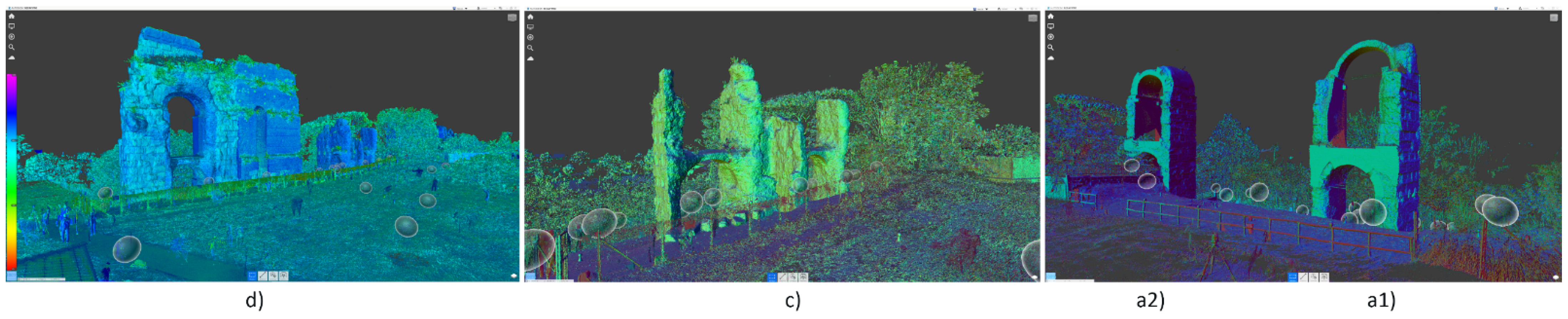