Article

Design and Evaluation of a Laminated Three-Phase Rotary Transformer for DFIG Applications

Department of Electrical and Electronic Engineering, Stellenbosch University, Stellenbosch 7600, South Africa
*
Author to whom correspondence should be addressed.
Energies 2022, 15(11), 4061; https://doi.org/10.3390/en15114061
Submission received: 14 April 2022 / Revised: 24 May 2022 / Accepted: 28 May 2022 / Published: 1 June 2022
(This article belongs to the Special Issue Wind Energy Technologies Development)

Abstract

:
In doubly fed induction generators (DFIGs), the rotor is excited through slip-ring and brush assemblies. These slip-ring and brush assemblies often require frequent routine maintenance, which affects the reliability of the DFIG. Alternatively, a contact-less energy transfer system, such as a rotary transformer, can be utilized in place of the slip rings. In DFIGs, the rotor frequency is very low, under 5 Hz, and this can lead to a huge rotary transformer since the transformer size is inversely proportional to its operating frequency. However, in a rotor-tied DFIG, whereby the rotor is connected directly to the grid whilst the stator is connected to a back-to-back converter, the rotor frequency becomes the grid frequency and can lead to a reasonably sized rotary transformer. In this paper, the design methodology of a three-phase rotary transformer that can be used in rotor-tied DFIG applications is proposed. The rotary transformer is coupled to the power windings of the rotor-tied DFIG and can improve its reactive power capabilities. The proposed methodology is validated with finite element analysis in 3D and can be used for an efficient design process with the proposed error correction. The proposed methodology is then applied in the design of a 6 kVA rotary transformer. Remarkable practical results are presented to demonstrate the effectiveness of the methodology. The rotary transformer is subsequently coupled to a rotor-tied DFIG and an acceptable performance is demonstrated for the entire system.

1. Introduction

The recent increase in both the adoption and the size of wind turbines has lead to the investigation of new generator topologies. In newer wind turbines, wound rotor machines (WRMs) are being employed as an alternative to permanent magnet (PM) machines. They offer significant advantages, such as the ability to regulate flux in the machine, which can control the power factor [1]. WRMs are cheaper to construct since they do not require the use of permanent magnets [2]. Doubly fed induction generators (DFIGs) remain the most popular generators employed in wind energy conversion systems [3]. DFIGs offer variable speed and power factor control, which makes them well suited for wind turbine applications. One of their primary drawbacks is poor reliability due to the use of slip-ring and brush assemblies [4,5].
Alternatively, the brushless DFIG (BDFIG) can be used in place of a DFIG [6,7,8,9,10,11,12]. The BDFIG does not have slip-ring and brush assemblies and does not suffer from the same reliability issues as the DFIG. However, the BDFIG is more complicated to design and manufacture. There are primarily two types of BDFIGs: the double stator BDFIG ([6,11]) and a rotary-transformer-based BDFIG ([7,10]). The rotor frequency of a BDFIG utilizing a rotary transformer is very low and thus a large rotary transformer would be required to transfer power to the rotor. A rotor-tied DFIG (RDFIG) has been proposed as a viable alternative to conventional DFIGs since it offers better performance and can have an improved usage of the rotor core [10,13,14]. In the RDFIG configuration, the rotor winding is connected directly to the grid while the stator is connected to the back-to-back converter transformer. Therefore, the rotor frequency is equal to the grid frequency. This provides for a better-sized rotary transformer when compared to a conventional DFIG topology since the transformer size is inversely proportional to the transformer frequency. It also allows the converter to operate the RDFIG around the synchronous speed, as a DC coupling through a rotary transformer is not possible in a standard DFIG. The converter rating for an RDFIG is similar to that of a conventional DFIG.
In a rotary transformer, an air gap is necessary to facilitate movement between the stationary and the rotating part. The existence of the air gap in a rotary transformer results in an increased leakage inductance and decreased magnetizing inductance [15,16,17]. This leads to larger magnetization currents and worse voltage regulation for rotary transformers when compared to similarly rated conventional transformers.
It has been demonstrated in the literature that it is possible to couple rotary transformers to standard DFIGs as shown in Figure 1 [7,18,19]. The inclusion of a rotary transformer on a rotor-tied machine allows for better grid fault ride through capabilities due to the increased inductance [20,21]. The rotor-tied DFIG has been shown to increase the reactive power generation range compared to traditional DFIGs [13]. Traditional and novel low-voltage ride through (LVRT) mitigation techniques such as a crowbar circuit should still be used in conjunction with the rotary transformer [13]. For example, LVRT compensating techniques that can be used are the dynamic voltage restorer (DVR), which is a series compensating technique, and the series grid side converter (SGSC) approach [22,23,24]. In [24], an SGSC connected at the Y-point of the DFIG system is proposed. This can be realized in the rotary-transformer-coupled RDFIG by adding an additional winding on the stator that couples magnetically with the primary power winding. The RT can be designed such that compensation can be applied to individual phases without affecting the operation of the other phases significantly. The cost of the rotary transformer may be offset by using such a technique, since the cost will remain relatively comparable with a double winding stator that can interface with the SGSC for an increased LVRT capability.
The main disadvantages of a rotary transformer for DFIG applications are its larger size, and the poor power factor and low efficiency that can be achieved by the rotary transformer plus DFIG configuration. A rotary transformer is inherently inductive in nature, which reduces the power factor range of the system. In [18], Lipo et al. proposed the use of a two-phase rotary transformer in a three-phase configuration to reduce the size of the rotary transformer by 35%. This setup led to an imbalance on the phases of the DFIG and the authors faced difficulties with the control system. Ruviaro et al. [7] proposed a radial air-gap rotary transformer with three separate phases at the low DFIG rotor frequency, which led to saturation.
In this paper, an analytical design methodology is presented that proposes several correction factors that account for the decreased lamination density in radially stacked rotary transformer cores. The design methodology is then used to design and evaluate several potential core layouts for an axial air-gap rotary transformer and is compared to 2D and 3D finite element analysis solutions. A proposed 6 kVA prototype is built and tested using the type III core design. The design combines all three phases on a single core with filler laminations on the rotor that increase the power density of the rotary transformer while decreasing losses. Remarkable practical results are presented to demonstrate the effectiveness of the methodology. The rotary transformer is also tested with a rotor-tied DFIG to determine an equivalent magnetic model and delivers acceptable performance at rated power.

2. Background

2.1. Three-Phase Rotary Transformers

Similar to conventional transformers, in order to reduce eddy currents, the transformer core is laminated for low-frequency rotary transformer applications. Due to the uniqueness of the rotary transformer, several solutions for arranging the laminations have been presented in the literature [8,18,25,26,27,28]. There are primarily three proposed methods of arranging the laminations in the rotary transformer, namely, radially stacked (Figure 2a), rolled and stacked (Figure 2b) and a combination of stacked flat-plane laminations (Figure 2c,d). Other lamination directions are possible but they are in the same direction as the current, and large eddy currents will be present.
The rotary transformer with radially stacked laminations with a radial air gap as proposed by [8] is shown in Figure 2a. This layout leads to a balanced amount of magnetic material with equal size and distance for the coils. However, large axial forces are experienced by the core during operation and each of the phases would need to have its own mounting mechanism. The second type of radially stacked cores is that of an axial air gap, as presented by [9,19,26]. This layout is difficult to manufacture with flat laminations, but it has no radial or axial forces and requires a basic frame. The downside of this type of layout is a low fill factor for the rotor. In [26], filler laminations were added to improve the fill factor and an efficiency of 91.4% was achieved.
In [28], the rolled and stacked rotary transformer layout was proposed to improve the fill factor of the radially stacked rotary transformer by using laminations in two different directions as shown in Figure 2b. Around the shaft the laminations are rolled, and for the limbs they are stacked in a similar manner to conventional machines. The fill factor that can be achieved is therefore similar to conventional machines and the power density is increased. The main drawback of the layout is the very tight tolerances that have to be achieved at the surface between the rolled and stacked sections, combined with the increased cost of manufacturing. This type of rotary transformer has not been verified experimentally, but it has a theoretical efficiency of 95.3%.
The third type of laminated rotary transformer, shown in Figure 2c,d, consists of sectional laminations as proposed in [18,27]. This can be realized either by a standard transformer core layout axially sliced and placed radially around a rotor as presented by [18], or in the form of axial and radial cores that are combined as presented by [27]. This type of construction reduces costs and simplifies manufacturing at the cost of reduced efficiency. To mitigate the size of the rotary transformer, Lipo et al. proposed that a two-phase rotary transformer could be used in a three-phase system, but a phase imbalance resulted [18]. The results shows that these proposed rotary transformers are prone to saturation. Note that the three-phase rotary transformers in Figure 2a,b can be realized through three separate single-phase rotary transformers. Mohabati et al. were able to reach an efficiency of 85% on their prototype [27].

2.2. Single-Phase Rotary Transformer Considerations

In this paper, the three-phase rotary transformer design process is based on the single-phase rotary transformer design method. The rotary transformer layout that is chosen is the one shown in Figure 3 with the laminations radially stacked. In the figure, reluctances along the flux path are shown. Therefore, in this section, the key design considerations for rotary transformers are presented.

2.2.1. Air-Gap Effects and Fill-Factor Correction

The air gap plays a significant role in the operation of the rotary transformer. An axial cutout transformer model is shown in Figure 3. From the model in Figure 3, the rotary transformer’s fill factor varies with the radius of the transformer. The fill factor of the stator can be calculated between its respective boundaries as
K f s = n s d l 2 π r x ,
and the fill factor of the rotor for the unfilled and equal filler lamination is
K f r u = n r d l 2 π r x , K f r f = n r d l π r x ,
where d l is the thickness of the laminations, and n s and n r are number of stator and rotor laminations, respectively. r x is as indicated in Figure 3. The stator fill factor is better than the rotor fill factor since there are fewer stacked laminations in the rotor. Hence, there is less magnetic material in the rotor. The poor rotor fill factor can be improved through the addition of rotor filler laminations [26]. No filler laminations are required for the stator. The addition of the filler lamination doubles the rotor core material at the air gap, and thus the effective air-gap area that the flux has to overcome can be calculated as
A e a g = 2 π r 3 · ( l 2 l 1 ) · δ ,
where r 1 , l 1 and l 2 are shown in Figure 3 and δ is the air-gap correction factor. δ is a function of the effective ratio of magnetic material at the air gap in the form of
δ = K f s K f r .
The effective air gap is the air gap including the lamination slotting. The addition of filler laminations results in better flux distribution in the air gap and thus a lower magnetizing current.

2.2.2. Reluctance Calculations

The electrical model of a rotary transformer is similar to that of a conventional transformer. The presence of the air gap and the varying cross-sectional area along the flux path combined with filler laminations leads to complex reluctance calculations in the case of a rotary transformer electrical model. The rotary transformer reluctance model is shown in Figure 3. The flux in a real rotary transformer cannot freely flow due to reluctance in the core. Each reluctance along a flux path section is calculated as
R x = l x μ A e x ,
where l x is the length of the flux path section, A e x is the core area section with the correction factor, and μ is the magnetic permeability of the core material. The total reluctance, R t o t a l , for a single-phase rotary transformer, as shown in Figure 3, can be calculated as
R t o t a l = R c p 1 + R c p 2 + R c p 3 + R c s 1 + R c s 2 + R c s 3 + R a g 1 + R a g 2 .
Then, the magnetizing inductance, L m , is given by
L m = N p 2 R t o t a l ,
where N p is the number of turns in the primary winding. The leakage inductance of the rotary transformer can be calculated from the energy of the magnetic field, which is equal to the magnetic energy of the leakage inductance in the winding volume (V); that is,
1 2 L l k I 2 = 1 2 V B · H d V .
For the proposed winding layout for Figure 3, Equation (8) simplifies to
L l k = π ( r 5 + r 2 ) N p 2 2 l 2 ( r 4 r 3 ) + ( r 5 r 4 ) + ( r 3 r 2 ) 3 ( 10 9 ) ,
with the leakage inductance equally split between the primary and the secondary winding; that is,
L l k p = 0.5 × L l k , L l k s = 0.5 a 2 × L l k ,
as a function of the turns ratio a. The magnetizing and leakage inductance are of particular concern as they greatly affect the electrical properties of the rotary transformer. The magnetizing inductance is affected by the length of the air gap, while the leakage inductance is only a function of the separation of the primary and secondary windings.

2.2.3. Winding and Core Losses

Generally, the total ohmic losses in the rotary transformer can be calculated as
P c u = j = 1 n ρ c N j M L T ( J A c j ) 2 A c j ,
where n is the number of windings in the rotary transformer, ρ c is the resistivity of the winding conductor, N j is the number of turns in the j th winding, M L T is the mean length of a turn in the windings, J is the current density and A c j is the wire conduction area of the j th winding. A higher current density will lead to higher copper losses.
The core losses in the rotary transformer consist of hysteresis, eddy current and stray losses. The sum of these losses, P c o r e can be analytically calculated using the adjusted Steinmetz Equation [29]; that is,
P c o r e = C h B α f + C e B m 2 f 2 + C a B m 3 / 2 f 3 / 2 ,
where C h , C e and C a are the hysteresis, eddy and additional loss coefficients of the specific non-grain-oriented electrical steel, respectively, α is the exponent of the flux density (B), B m is the mean flux density and f is the frequency. Equation (12) has some limitations and is only valid in materials which are not heavily saturated.
Alternatively, the core losses can be calculated by using a combined model from the lamination manufacturer’s data sheet at the specific flux density. The core loss is given by
P c o r e = V · W l o s s · ρ
where V is the volume of the active material, W l o s s is the manufacturer’s loss constant and ρ is the density of the material. In this method, it is assumed that the core is being used in a similar manner as it was when the empirical model was derived. Most finite element analysis (FEA) software use this technique since it is accurate when the flux density for each small section is separately evaluated.

3. Three-Phase Rotary Transformer Design

In this section, the design process for a three-phase rotary transformer is presented. The three-phase rotary transformer under consideration consists of three independent single-phase rotary transformers; therefore, the design of a single-phase rotary transformer is initially given.

3.1. Design Process of a Rotary Transformer

The flowchart of the design process of a radially laminated, single-phase rotary transformer is shown in Figure 4.
Once the design specifications have been finalized, the electrical (J) and magnetic loadings (B) are selected. Typically, the starting/maximum current density is set at J m a x = 5 A/mm2 when air cooling is considered. The chosen core material’s saturation flux density ( B s a t ) is used as the initial value of the flux density ( B o ). Alternatively, the method described in [30] can be used in determining the initial value of the flux density. The window utilization factor, K u , is given by
K u = W c W a ,
where W c and W a are the copper area and window area, respectively.
The area product can be used to calculate the dimensions. Combining Faraday’s law of induction and Ampere’s law, the power capability of a transformer of the rotary transformer can be calculated as
P V A = π J K u f B o A p ,
where B o is the peak flux density and A p is the area product of the rotary transformer. With the design specifications and loadings known, the area product can be calculated from Equation (15). The area product is also given by
A p = A e c × A w = A c K f x × A w ,
which is useful, since it allows for a design that can favor efficiency or magnetic coupling by setting the ratio between the effective core area, A e , to the winding area, A w . The area product represents the physical sizing that the rotary transformer is constrained to in terms of the power rating. Achieving a high power density is reliant on a high lamination fill factor ( K f ). This can be problematic in designs such as the radially laminated rotary transformer, where the fill factor changes with radial distance. The winding fill factor depends on the type of winding material, and for round wire in a simple configuration, the upper limit is typically 0.6.
The number of turns, N, is calculated from the design specifications using
N = V r m s 4.44 f B o A e c .
From the area product, a ratio between the winding area and the core area can be determined, and therefore, the core dimensions can be calculated from simple geometrical equations. Since this process is iterative, the core and winding areas are calculated iteratively until a satisfactory area product is achieved. After the core dimensions and parameters are set, the magnetizing and leakage inductances are determined, and the approximate peak operating flux density can be determined as
B o p e a k = V p e a k 4.44 f N p A e c .
If the operating flux density is feasible, then the losses can be calculated and the efficiency can be compared to the design specification.

3.2. Three-Phase Rotary Transformer Connection

Once the single-phase rotary transformer design has been completed, the three-phase rotary transformer can then be formed using three single-phase rotary transformers. Similarly to conventional transformers, the possible three-phase rotary transformer configurations are Y–Y, Y–Δ, Δ–Y and Δ–Δ. The rotary transformers connected in the Y–Y and Δ–Δ configurations are shown in Figure 5. The Y–Y connection is chosen in this paper.

3.3. Lamination Design Options

Once the design dimensions have been set, the core lamination layout can be considered. To reduce the eddy current effects, the laminations are stacked perpendicularly to the direction of the current flow. The proposed method is for radially laminated cores but the method is similar for other stacking types.
The design can utilize single-phase rotary transformers in a three-phase configuration, resulting in three identical lamination stacks, referred to in Figure 6 as type I. This increases the manufacturing cost due to a threefold increase in lamination count, as well as the structure to support them. This reduces the power density for the benefit of no mutual coupling between the phases. This can be a viable option if cooling constraints are present. The layout is the least susceptible to coupling changes.
The second core type (type II) is the shared limb configuration, which saves space by sharing the inner limbs of the core between phases. This results in a single sheet of lamination that offers better power density and has a reduced weight and cost at the expense of being difficult to cool and being more susceptible to coupling changes. Small air-gap changes can significantly affect the balance of this configuration, and it is more susceptible to vibrations and harmonics. This configuration is most common with conventional transformers, as they do not share the same drawbacks as the rotary transformer.
The third configuration (type III) is that of separated phases on a single lamination sheet. The sheet has ribs that connect and space the individual limbs from each other, resulting in only a partial mutual flux. This reduces the cost of manufacturing but has similar power density and coupling characteristics to the single-phase configurations. The ribs will experience saturation which limits the mutual flux to other phases. The ribs have the highest temperature concentration of the laminations, but, because of the spacing and rotation, they have enough air flow not to overheat. This layout is the best compromise for rotary transformers that are built as prototypes due to its resilience to coupling changes.

4. Six kVA Rotary Transformer Design Example

To demonstrate the effectiveness of the design method presented in this paper, a three-phase WYE-connected, 6 kVA, 400 V rotary transformer was designed and experimentally evaluated. The transformer consists of three separate 2 kVA single-phase transformers and its winding ratio is selected to be 1:1. The design requirements are shown in Table 1.
The selected core material was M400-50A steel with B s a t = 1.5 T and the window utilization factor for the enameled round copper wire was set at K u = 0.6.
The core was radially laminated, and a stator and rotor fill factor of 0.8 was chosen, whereby filler laminations were considered 1:1 in the rotor. The current density was set at J m a x = 5 A/mm2 for air-cooling requirements. Achieving such a high current density was not feasible for the rotary transformer due to the internal winding on the rotor being difficult to cool. The achieved current density was 1.6 A/mm2 on the rotor to achieve the efficiency target of the design, resulting in a lower-power-density rotary transformer.

4.1. Single-Phase Rotary Transformer Parameters and Dimensions

Following the design process from the previous section, the dimensions of the 2 kVA single-phase rotary transformer are shown in Table 2. Furthermore, the number of turns in the stator and rotor was 178 turns.

4.2. Lamination Evaluation

Finite element analysis (FEA) results of the three lamination configurations, as presented in the previous section, for the three-phase rotary transformer are presented in this section. ANSYS Maxwell 2/3D was used and the analysis was performed in both 2D and 3D FEA for comparison with a discretization of 0.0001 s with a backwards Euler solver accuracy of 1 × 10 6 . The presented configurations were all connected in Y–Y and the analysis was performed under open circuit conditions, whereby the rotor side was excited at the rated operating voltage of 230 V per phase. All three lamination configurations had filler laminations on the rotor. 
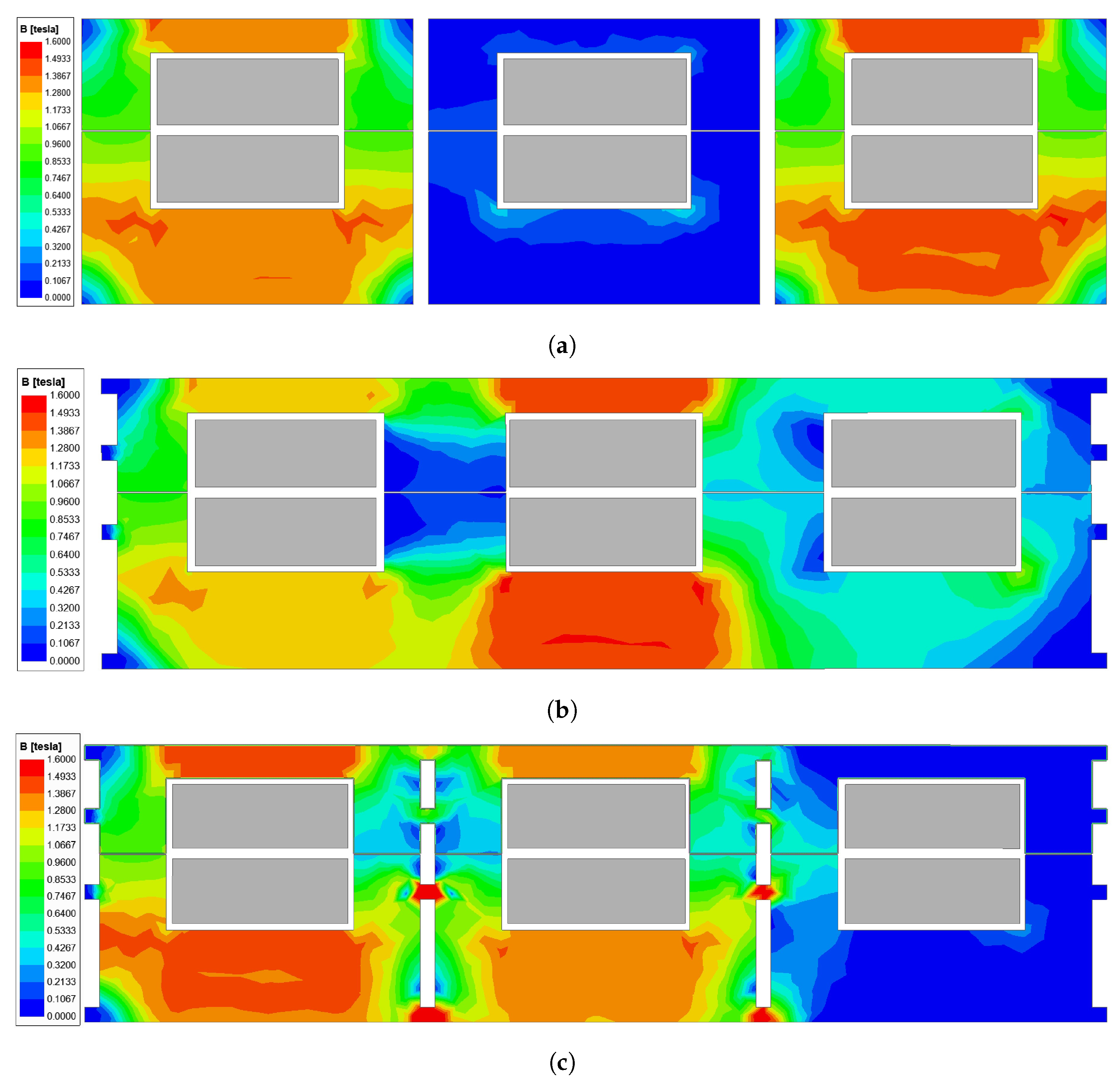
Figure 7 shows the peak flux density at 325 V.
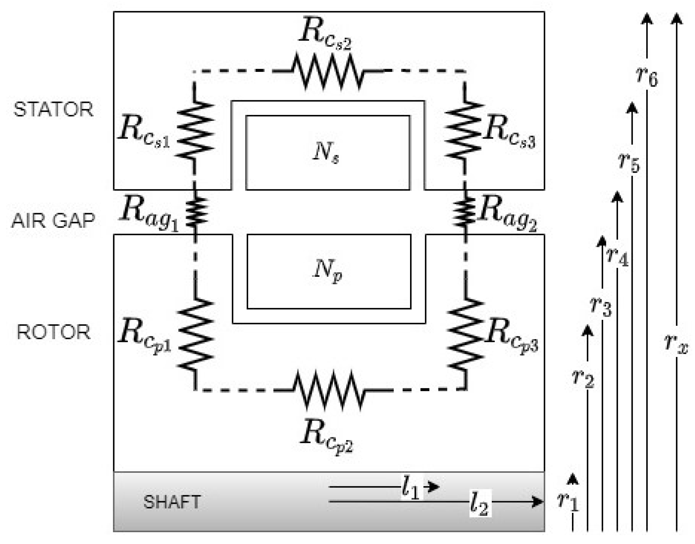
A key factor in the dynamic performance of the rotary transformer is the leakage inductance. The leakage inductance has the largest impact on the voltage regulation. An increase in the winding width and a decrease in the distance between the coils are required to improve coupling and thus reduce the leakage inductance. Special care has to be taken when simulating for leakage inductance, as most 2D FEA software cannot compute it accurately due to the rotary transformer’s laminations and the unconventionality of the air gap. The inductance is calculated as a full inductance matrix and converted to magnetization and leakage inductance per phase. To evaluate the accuracy of the FEA solution, a 2D simulation was run in the axisymmetric mode with a decreased lamination density to equal the amount of magnetic material present in the 3D model.
A 3D quarter model simulation with individual lamination sheets was used to verify the results and compare them against analytical calculations with error correction as presented in this paper. The results of these simulations on the rotary transformer model are shown in Table 3. The 2D simulations showed an increased magnetization inductance, which resulted in lower open circuit currents for all three proposed topologies. The 3D FEA and analytical calculations had similar magnetization inductance values for all three rotary transformers, at around 14% lower than the 2D FEA.
The leakage inductance was computed as much lower in the 2D FEA simulations for all cases, resulting in an assumption that the rotary transformer is capable of a better dynamic voltage regulation than it can achieve. The 3D FEA provided a higher leakage inductance in all three cases and was assumed to be accurate if there were no winding errors and if the coils were placed exactly in the same positions as the simulation. The analytical calculation was much more conservative, taking into account the expected tolerances on the winding size, fill factor and placement. The analytical solution was chosen as it represents a worst-case scenario and is more practicable on a prototype when the correction factors discussed in Section 2.2.1 are used.
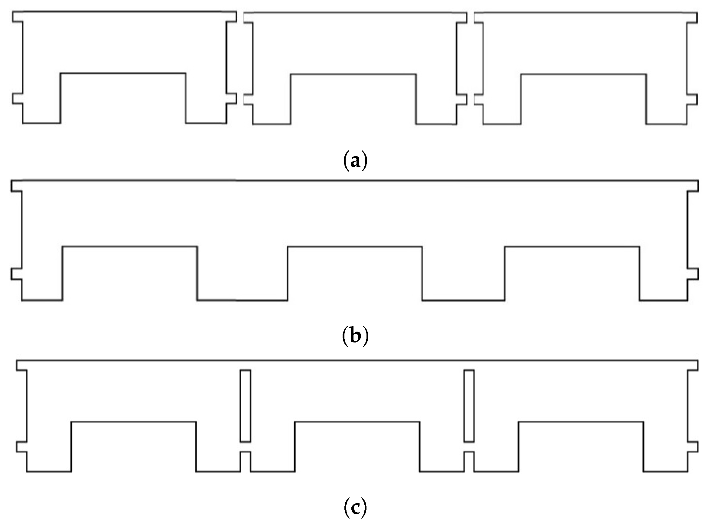
The type I configuration had no leakage flux between phases, as seen in Figure 7a. The rotary transformer operated below the saturation point of the core material. It can be observed from the figure that the core material on the stator was not as effectively used as on the rotor. The phase currents were well balanced, as shown in Figure 8.
The results of the rotary transformer type I are shown in Figure 7b. This configuration resulted in a high power density of 445 kW/m3 at the cost of coupling stability, and it was the default configuration for conventional transformers. The rotary transformer operated below the saturation point of the core material with a mutual inductance between phases of 0.4 PU at open circuit. The center phase had a reduced magnetization current, as shown in Figure 8.
For the type III rotary transformer, the flux density plot is shown in Figure 7c. Saturation was observed on the ribs joining the single-phase laminations. The ribs saturated at 108 V per phase, which causes additional localized losses. The mutual flux between the phases amounted to a reduced magnetizing current requirement in phase B, similar to conventional shell-type transformers. The open circuit magnetization currents for the 3D FEA can be seen in Figure 8.
Comparing the proposed topologies, it is clear that the type I rotary transformers had the best operating characteristics with respect to what their inductances indicate. This correlates with previous research conducted by [8,9,19,31] which all utilized single-phase rotary transformers. The primary disadvantages of this solution are the increased cost and manufacturing requirements, the reduced power density of 390 kW/m3 and the increased transformer size. The type II topology had the highest power density and lowest cost, but the worst performance at low loads and an increased leakage inductance. The power density requirements can, however, still make this a viable topology as the voltage regulation was about 8% worse during phase B than the single-phase rotary transformer configuration at full load. The average voltage regulation values for the rotary transformers are shown in Table 4.
The ribbed topology offers reduced cost and complexity, while still maintaining a partial separation of flux from the phases by the use of small ribs between the phases. The topology has a reduced power density compared to the type II topology at 405 kW/m3, but allows for the ability to cool the inner phase while still retaining a similar leakage as the shared limb.
In this paper, the type III configuration was chosen due to the uncertainty of cooling the inner phase without significant measures being taken, such as cooling the shaft internally. It allows for forced air cooling to be used, as the spaces between the phases are large enough. The topology can also be designed as a single phase, as it has comparable characteristics and dimensions to the single-phase design.
At full load, all three topologies operated at below the materials saturation point of 1.5 T. The type I rotary transformer configuration had the lowest core losses of 107 W at full load, while the type II and III configurations had full-load core losses of 112 W and 109 W, respectively. All three topologies had the same winding configuration and therefore similar conduction losses.
Although the type I configuration performed better, the increased cost and manufacturing requirements as well as the low power density makes the type III configuration a more suitable design, as it does not compromise excessively on any of the important characteristics of the rotary transformer.

4.3. Experimental Evaluation

To evaluate the accuracy of the analytical and FEA models, a prototype was manufactured. The frame, shaft and end plates were all made from stainless steel 316, while the laminations were M400-50A non-grain-oriented steel. The winding material was enameled copper wire connected in a Y–Y configuration.
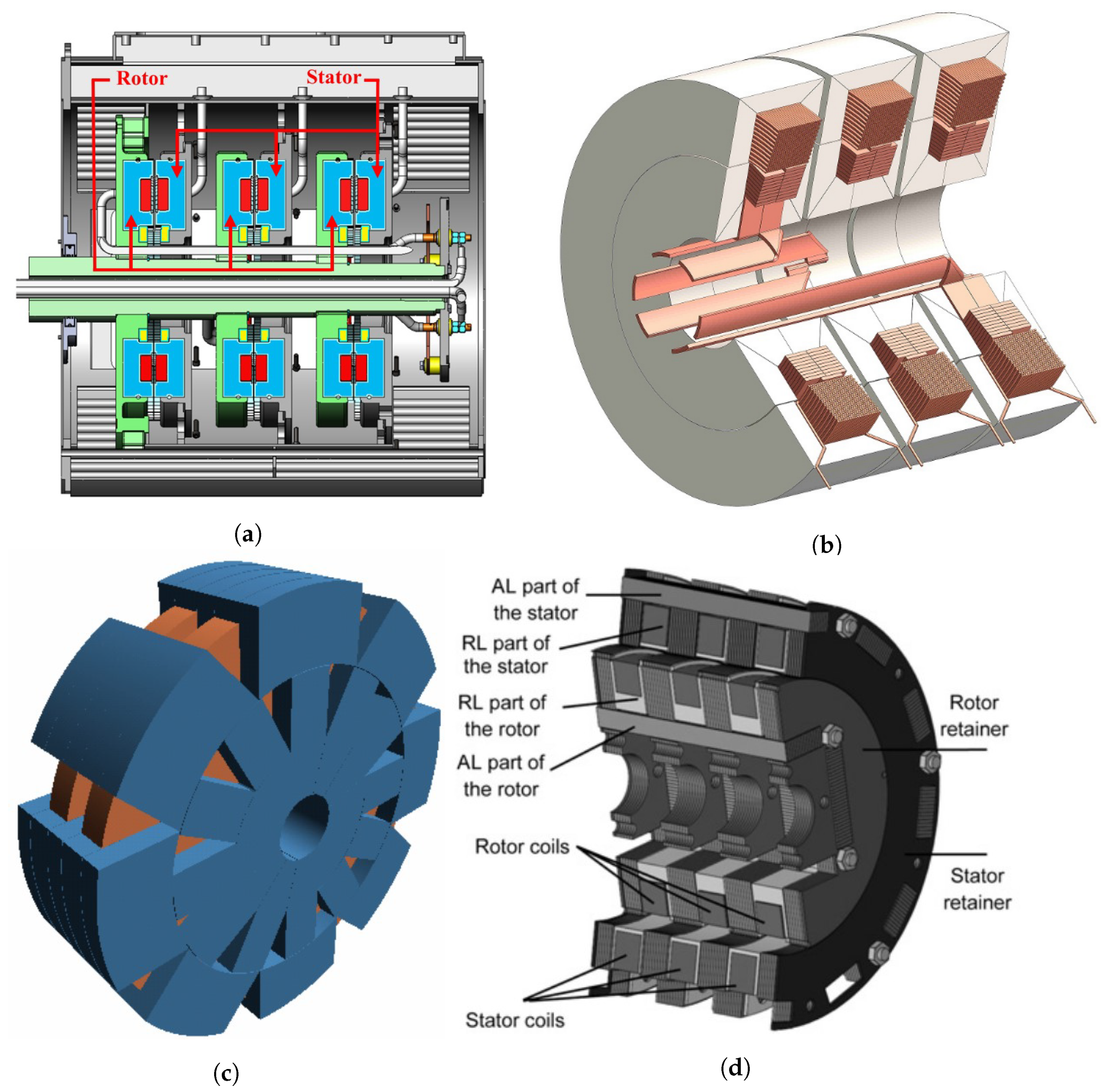
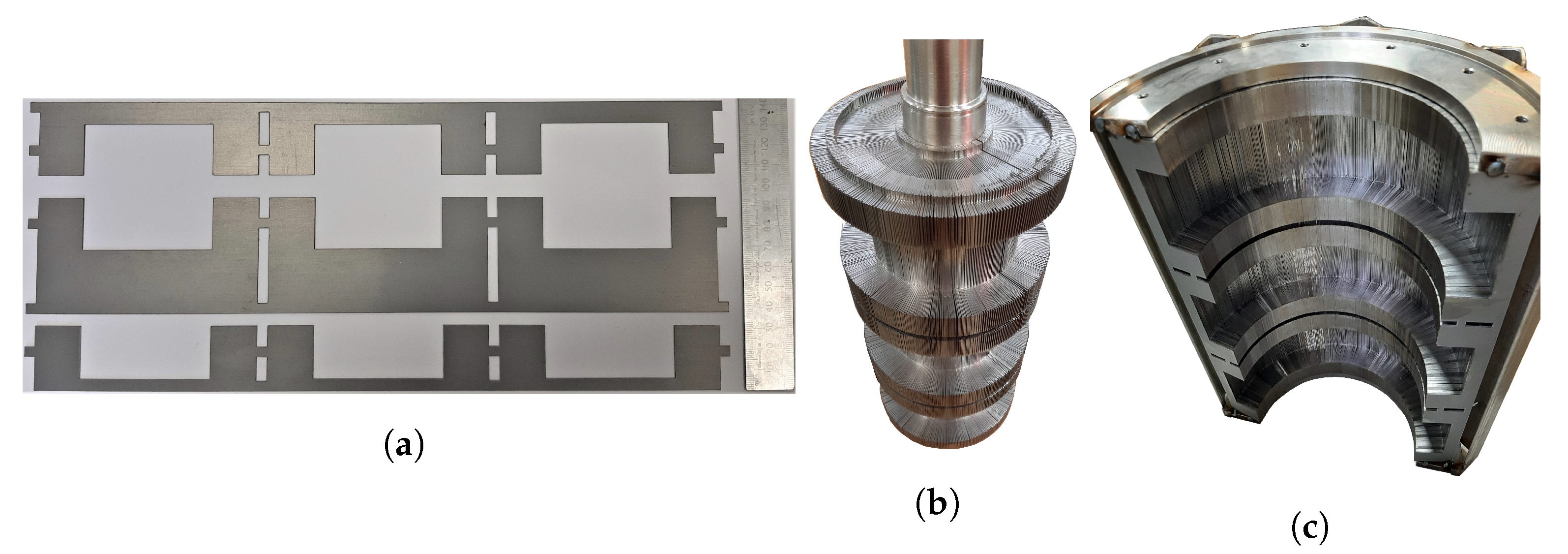
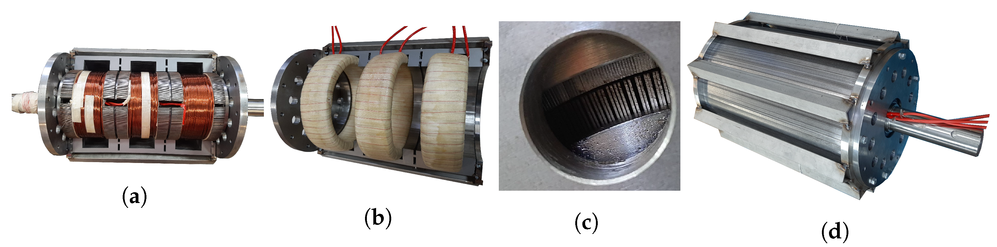
The manufactured rotary transformer laminations and filler laminations are shown in Figure 9a, and the stacked rotor and stator laminations can be seen in Figure 9b. The wire terminals were internally connected in Y during the assembly process in order to reduce the slot size. Figure 10a shows the completed rotor during a test fit in the stator. The achieved rotor winding fill factor was 0.63 with a stacking fill factor of 0.7.
The stator of the rotary transformer had to be made in two halves to accommodate the coils in the inside. The stator coils were wound and then baked in resin to keep them in shape. The achieved fill factor for the stator coils was 0.58, with a stacking fill factor of 0.75. The coils can be seen in one half of the stator in Figure 10b. No filler laminations were added in the stator. The stator lamination can be seen in the completed half of the stator in Figure 9c.
The different assembly stages are shown in Figure 10. The achieved air gap of the prototype had a range between 0.5 and 0.7 mm, with 0.6 mm being the average. This mostly affects magnetizing inductance.

4.3.1. Equivalent Circuit Parameter Measurements

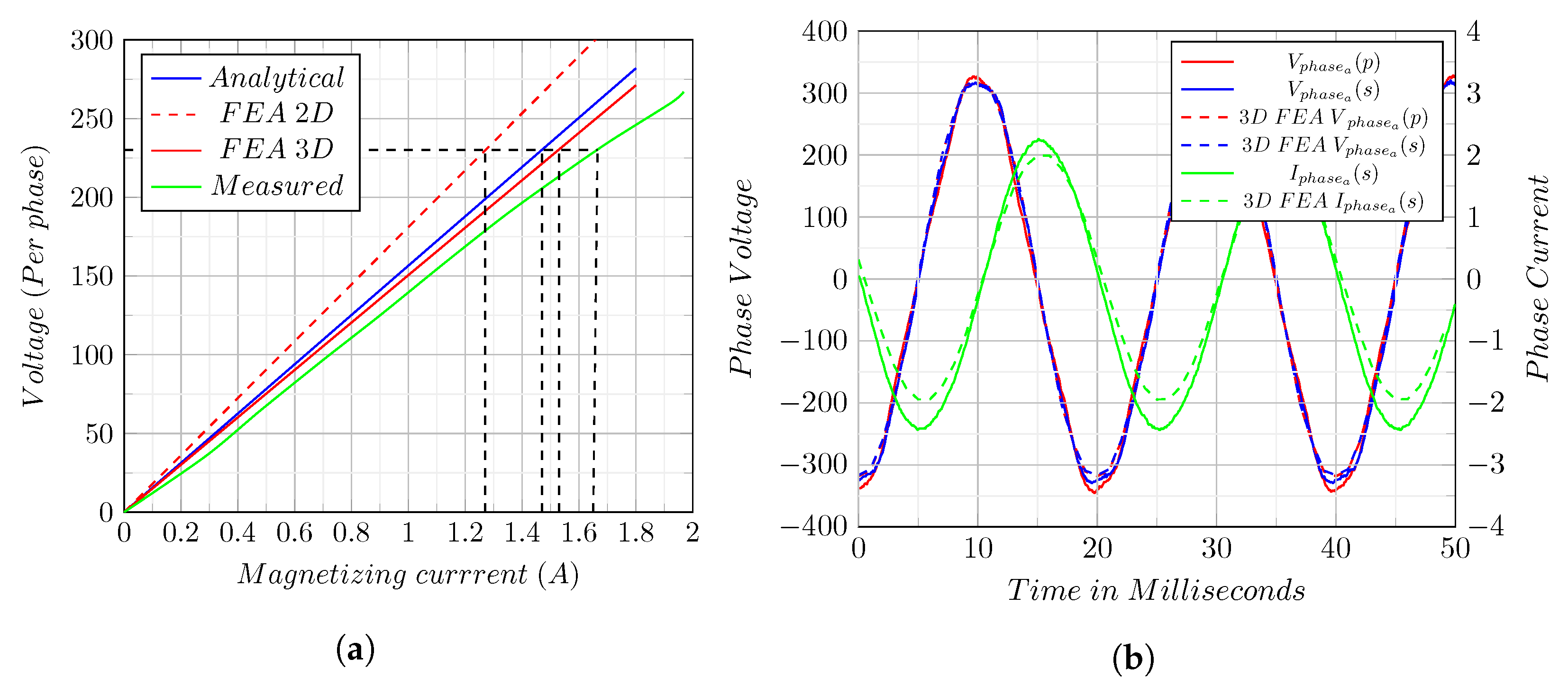
The open circuit voltage versus supply current characteristic is shown in Figure 11a. In this figure, it is clear that the 3D FEA result was the closest to the measured one, with only a 7.54% deviation. Surprisingly, the analytically calculated characteristic was also better than the 2D FEA result due to the correction factors at only a 11.5% deviation from the measured results. Therefore, care needs to be taken when using 2D FEA in rotary transformer analysis. The primary and secondary induced voltages and currents are shown in Figure 11b. The FEA results and the measurement results compare very well. The equivalent circuit parameters are shown in Table 5. An LCR meter was used to measure the inductances. Furthermore, the equivalent circuit parameters were calculated from the open circuit (OC) and short circuit (SC) tests. A good correlation between the analytical, FEA and measurement results can be observed in Table 5. The largest calculation error was expected for the open circuit case.

4.3.2. Full-Load Test

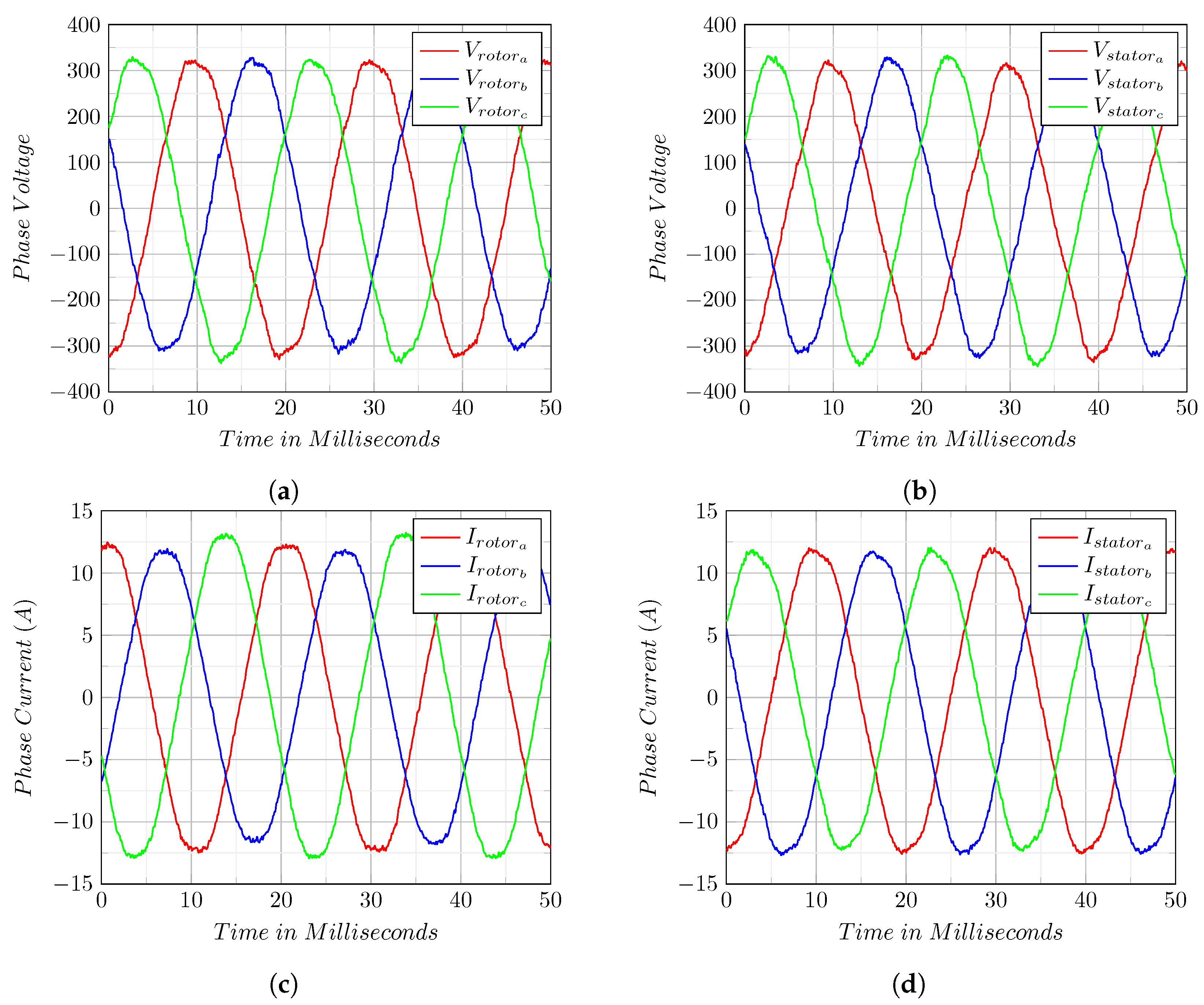
The full-load test was conducted while the rotary transformer was kept stationary. The measured voltage and current waveforms are shown in Figure 12. The measurement results at rated input voltage, rated output voltage and 1.3 PU load are shown in Table 6. In all the conditions in 
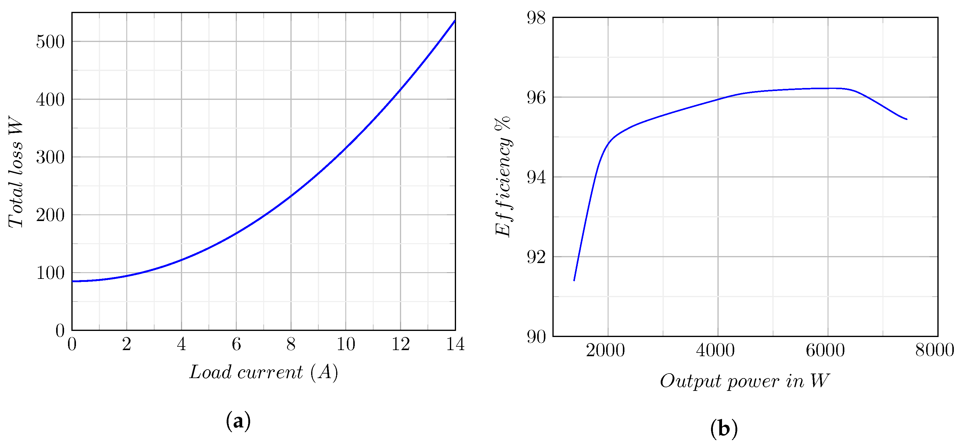
Table 6, the measured efficiency was above 95 % at a power factor above 0.9. The voltage regulation of the rotary transformer was on average at 6%, but phase C had a lower voltage regulation of 8%, possibly due to higher leakage inductance. The total harmonic distortion was measured to be 1.6% for the output voltage. The total losses (core, hysteresis and copper) curve is shown in Figure 13a and the efficiency curve at the rated input voltage is shown in Figure 13b.

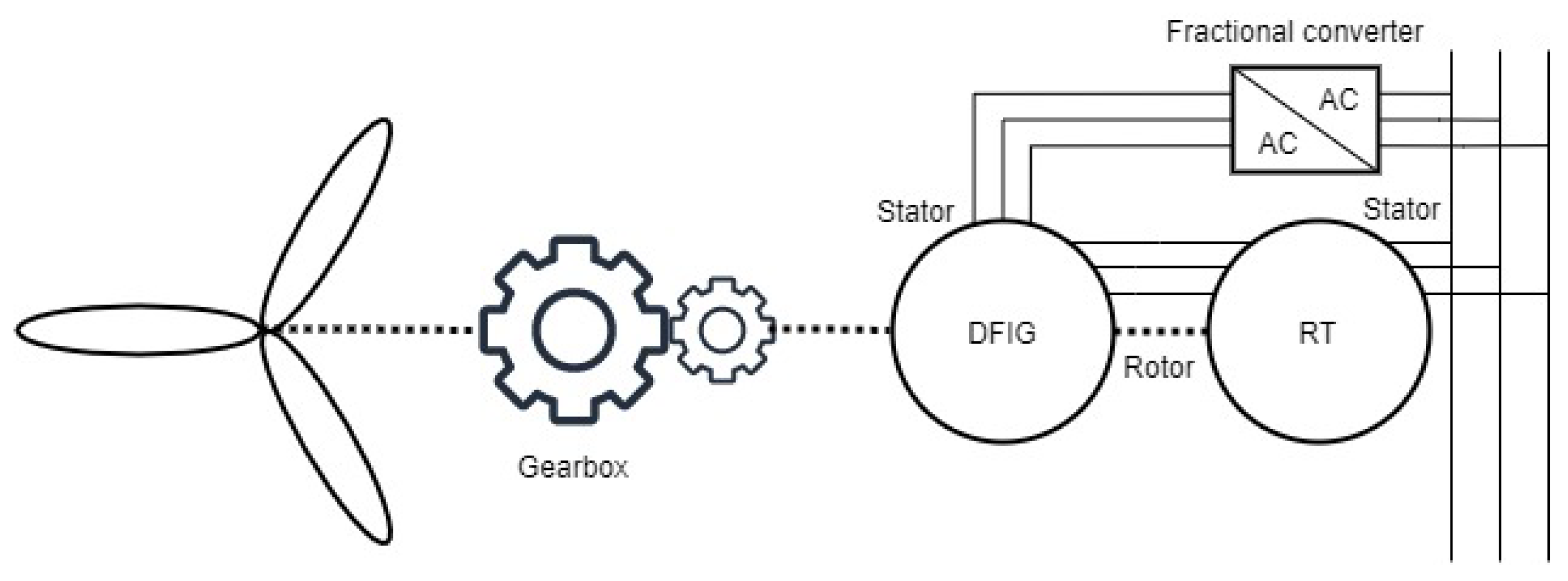
4.3.3. Rotary Transformer–RDFIG Coupling Parameter Tests

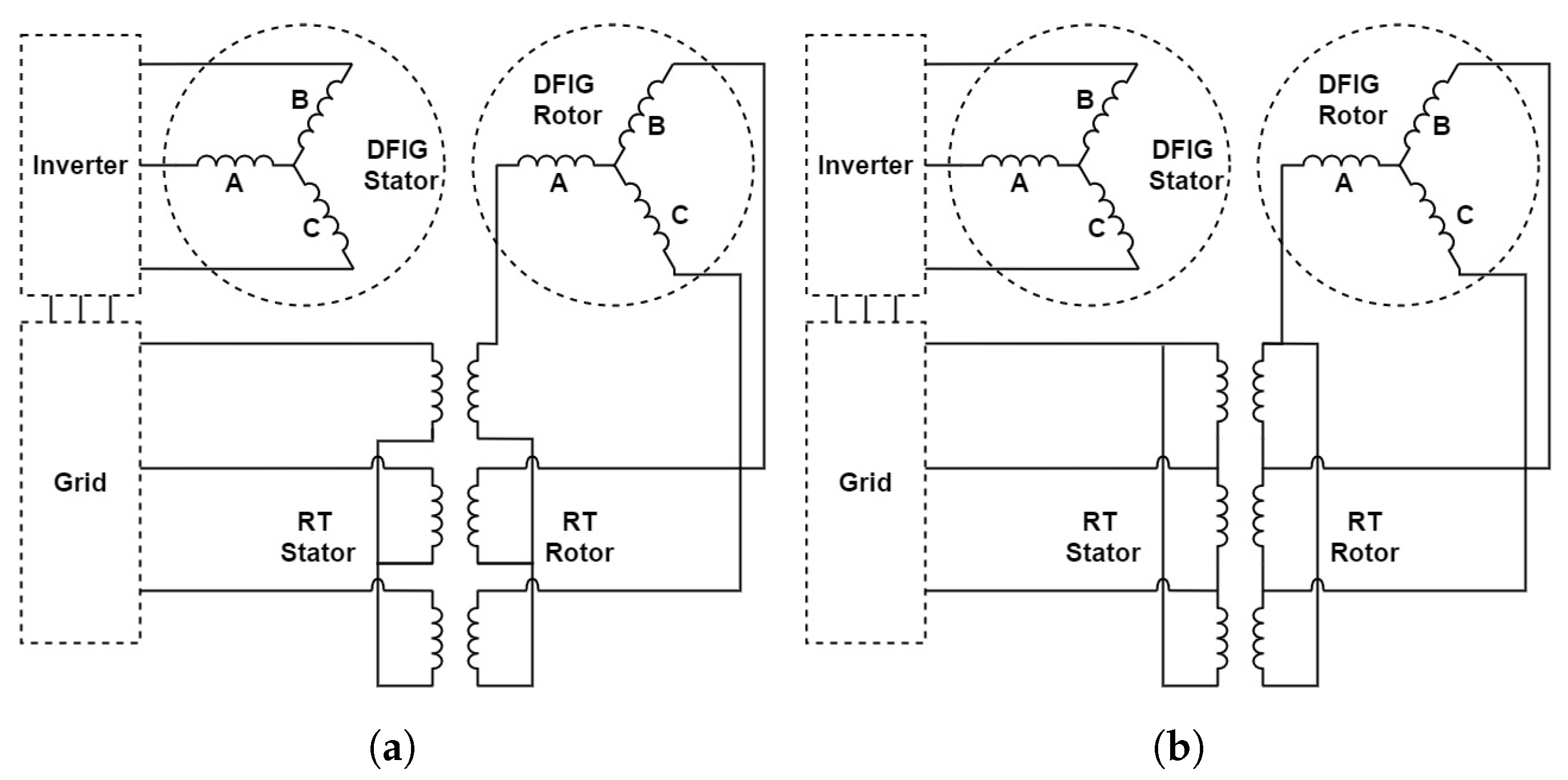
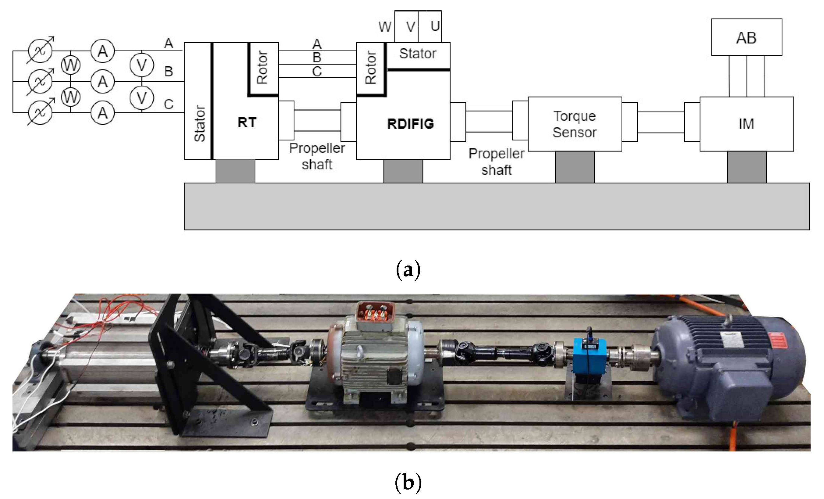
The rotary transformer was then loosely coupled to a 5.5 kW, four-pole rotor-tied-DFIG (RDFIG) prototype that was developed by [14]. The power rating of the rotor of the RDFIG was not matched to that of the rotary transformer, but it provided a suitable test platform to investigate the rotary transformer’s performance at rated speed. The slip-ring and brush assembly were removed from the RDFIG and the rotor could only be accessed through the rotary transformer. The test setup and connection diagram are shown in Figure 14.
The rotary transformer–RDFIG setup was tested under a no-load condition at a synchronous speed. The stator (control) windings were open circuit on the RDFIG, with an induction machine supplying mechanical power to the setup at 1500 rpm. The no-load tests can be seen in Table 7 with all the parameters shown as if the rotary transformer–RDFIG were tested as a single system. The rotary transformer increased the power required by the RDFIG to achieve rated voltage due to extra magnetization requirements. The rotary transformer was an inductive load; therefore, the power factor was very low, which was to be expected. The blocked rotor test was conducted with the machine at a standstill; the control windings were shorted and the voltages increased until the rated rotor current was reached. The test results are shown in Table 8.
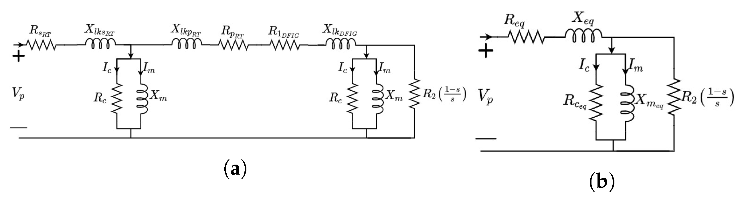
The full equivalent circuit of the rotary transformer–RDFIG was a cascaded circuit consisting of both the rotary transformer and the RDFIG (Figure 15a). Analyzing this circuit is difficult; therefore, the new equivalent circuit model for the rotary transformer–RDFIG is presented as a simplified model and can be seen in Figure 15b. The series inductance and resistance were combined into a single variable, while the two magnetizing branches were assumed to be in parallel and combined into one equivalent branch. The final parameters measured from the no-load and blocked rotor tests are shown in Table 9.

4.3.4. Rotary Transformer–RDFIG Load Testing

To test the output power of the rotary transformer–RDFIG, the RDFIG was operated at a synchronous speed and unity power factor. A DC current was applied to the stator of the RDFIG with resistive loads to ensure a unity power factor on the output. Due to the lagging PF of the rotary transformer, the RDFIG had a leading internal PF, reducing the efficiency of the system. The test results are shown in Table 10.
The RDFIG was able to operate at an efficiency of 87% when measured in the synchronous mode, with a total harmonic distortion on the voltage of 3.83%. The rotary-transformer-coupled RDFIG achieved an efficiency of 82% due to the additional losses of adding the the rotary transformer to the setup compared to the slip-ring assembly, but due to the increased series inductance, both the voltage and current total harmonic distortion were much lower, at 1.93% and 1.85%, respectively. The test proves that the rotary transformer can be used to couple the RDFIG without the use of a slip-ring and brush assembly.

5. Conclusions

The three-phase rotary transformer is intended to replace the slip rings of a DFIG, making the system contact-less and reducing the need for regular maintenance. The use of an RDFIG significantly reduces the size of the rotary transformer due to the increased rotor frequency. The use of an RDFIG differentiates the approach followed by other prototypes, as the rotary transformer is used for power transfer rather than contact-less rotor coupling with the power winding on the stator [8]. This allows the RDFIG to operate around its synchronous speed, as opposed to a rotary-transformer-coupled DFIG in which the DC coupling from the converter to the rotor would not be possible. The general design methodology of a three-phase, rotary transformer was presented in this paper. Different topologies and lamination layouts were discussed as well as the air-gap effects. Correction factors for a radially laminated, axial air gap were presented and compared to 2D and 3D FEA results. A proposed 6 kVA three-phase axial air-gap rotary transformer was presented with the type III lamination layout for validation with a manufactured prototype.
The prototype compares favorably to the analytical design and 3D FEA results in its magnetic properties. The rotary transformer is able to maintain an efficiency that is higher (by 96%) than other tested prototypes [27,28,31]. The resizing of the winding width to the height ratio yielded a rotary transformer that has a significantly lower leakage and a higher magnetizing inductance compared to other prototypes, resulting in a lower impedance percentage and a lower magnetization current [8,19,27]. The rotary transformer was able to deliver up to 1.3 PU at the expense of reduced efficiency, power factor and thermal stability. The proposed rotary transformer also did not saturate at the designed operating voltages, a problem that other prototypes have experienced [31]. The rotary transformer was then coupled to an RDFIG and new equivalent parameters was calculated. The rotary-transformer-coupled RDFIG was load-tested at a synchronous speed to demonstrate that the rotary transformer can indeed be used for successful coupling at a reduced efficiency. The increased series inductance could help the low voltage ride through the capabilities of the rotary-transformer-coupled RDFIG, and this should be investigated further.

Author Contributions

Investigation, S.B. and N.G.; Methodology, S.B. and N.G.; Project administration, S.B.; Supervision, N.G.; Writing—original draft, S.B.; Writing—review & editing, N.G. All authors have read and agreed to the published version of the manuscript.

Funding

This research received no external funding.

Institutional Review Board Statement

Not applicable.

Informed Consent Statement

Not applicable.

Data Availability Statement

The data presented in this study are available within this study.

Acknowledgments

The authors acknowledge the staff at the Electrical Machines Laboratory at Stellenbosch University for their technical assistance.

Conflicts of Interest

The authors declare no conflict of interest.

Abbreviations

The following abbreviations are used in this manuscript:
DFIGDoubly fed induction generator
WRMWound rotor machines
BDFIGBrushless doubly fed induction generator
RDFIGRotor-tied DFIG
PFPower factor
MLTMean length of turn
FEAFinite element analysis

References

  1. Cao, W.; Xie, Y.; Tan, Z. Wind Turbine Generator Technologies. Intech 2016, 13. Available online: https://www.intechopen.com/books/advanced-biometric-technologies/liveness-detection-in-biometrics (accessed on 13 April 2022).
  2. Xue, P.; Lin, J. Discussion on the Rare earth resources and its development potential of Inner Mongolia of China. In Proceedings of the 2011 International Conference on Materials for Renewable Energy & Environment (ICMREE2011), Shanghai, China, 20–22 May 2011; Volume 1, pp. 9–12. [Google Scholar]
  3. GWEC Global Wind Report 2018. Wind Energy Technol. 2019, 61. Available online: www.gwec.net (accessed on 13 April 2022).
  4. Reder, M.; Gonzalez, E.; Melero, J. Wind Turbine Failures—Tackling current Problems in Failure Data Analysis. J. Phys. Conf. Ser. 2016, 753, 072027. [Google Scholar] [CrossRef]
  5. Pfaffel, S.; Faulstich, S.; Rohrig, K. Performance and reliability of wind turbines: A review. Energies 2017, 10, 1904. [Google Scholar] [CrossRef] [Green Version]
  6. McMahon, R.; Tavner, P.; Abdi, E.; Malliband, P.; Barker, D. Characterising rotors for brushless doubly-fed machines (BDFM). In Proceedings of the 19th International Conference on Electrical Machines (ICEM 2010), Rome, Italy, 6–8 September 2010; Volume 2. [Google Scholar]
  7. Ruviaro, M.; Runcos, F. A brushless doubly fed induction machine with flat plane rotary transformers. In Proceedings of the 2012 20th International Conference on Electrical Machines (ICEM 2012), Marseille, France, 2–5 September 2012; pp. 23–29. [Google Scholar]
  8. Ruviaro, M.; Rüncos, F.; Sadowski, N.; Borges, I. Analysis and test results of a brushless doubly fed induction machine with rotary transformer. IEEE Trans. Ind. Electron. 2012, 59, 2670–2677. [Google Scholar] [CrossRef]
  9. Ruviaro, M.; Rüncos, F.; Sadowski, N. Wound Rotor Doubly Fed Induction Machine with Radial Rotary Transformer. J. Microw. Optoelectron. Electromagn. Appl. 2013, 12, 411–426. [Google Scholar] [CrossRef]
  10. You, Y.; Lipo, T.; Kwon, B. Design and analysis of a novel grid-connected to rotor type doubly fed induction machine. IEEE Trans. Magn. 2012, 48, 919–922. [Google Scholar] [CrossRef]
  11. Tavner, P.; Abdi, E.; Tatlow, M.; McMahon, R. Design and performance analysis of a 6 MW medium-speed brushless DFIG drivetrain. In Proceedings of the 2nd IET Renewable Power Generation Conference (RPG 2013), Beijing, China, 9–11 September 2013; Volume 2, pp. 977–983. [Google Scholar]
  12. Resmi, R.; Agoram, C.; Adithya, P.; Vanitha, V. Design and Analysis of Brushless Doubly Fed Induction Generator. SMART GRID Technol. 2015, 21, 604–610. [Google Scholar] [CrossRef] [Green Version]
  13. David, N.; Wang, Z. Rotor-Tied Configuration of DFIG Wind Turbines for Improving Reactive Power Support Capability. IEEE Power Energy Soc. Gen. Meet. 2018, 2018, 1–5. [Google Scholar]
  14. Olubamiwa, O.; Gule, N. The optimal design and autonomous testing of a rotor-tied DFIG. In Proceedings of the 2017 IEEE AFRICON: Science, Technology and Innovation for Africa, Cape Town, South Africa, 18–20 September 2017; pp. 1378–1383. [Google Scholar]
  15. Ruviaro, M.; Rüncos, F.; Sadowski, N.; Borges, I. Design and Analysis of a Brushless Doubly Fed Induction Machine with Rotary Transformer. In Proceedings of the 19th International Conference on Electrical Machines (ICEM 2010), Rome, Italy, 6–8 September 2010; pp. 1–6. [Google Scholar]
  16. Smeets, J.; Encica, L.; Lomonova, E. Comparison of winding topologies in a pot core rotating transformer. In Proceedings of the 2010 12th International Conference on Optimization of Electrical and Electronic Equipment, Brasov, Romania, 20–22 May 2010; pp. 103–110. [Google Scholar]
  17. Shang, J.; Wang, H.; Cong, N.; Zou, J.; Liu, X. The calculation of inductance parameter for wounded rotating transformer. In Proceedings of the 2015 15th International Conference on Instrumentation and Measurement, Computer, Communication and Control (IMCCC), Qinhuangdao, China, 18–20 September 2015; pp. 157–160. [Google Scholar]
  18. Lipo, T.; Panda, D.; Zarko, D. Design and Test of DC Voltage Link Conversion System and Brushless Doubly-Fed Induction Generator for Variable-Speed Wind Energy Applications: August 1999–May 2003; National Renewable Energy Lab. (NREL): Golden, CO, USA, 2005. [Google Scholar]
  19. Zhong, H.; Wu, C.; Wang, Y. Design and analysis of rotary transformer for brushless doubly fed induction generators. In Proceedings of the 2018 13th IEEE Conference on Industrial Electronics and Applications (ICIEA), Wuhan, China, 31 May–2 June 2018; pp. 1416–1419. [Google Scholar]
  20. Tohidi, S.; Tavner, P.; McMahon, R.; Oraee, H.; Zolghadri, M.; Shao, S.; Abdi, E. Low voltage ride-through of DFIG and brushless DFIG: Similarities and differences. Electr. Power Syst. Res. 2014, 110, 64–72. [Google Scholar] [CrossRef]
  21. López, J.; Sanchis, P.; Roboam, X.; Marroyo, L. Dynamic behavior of the doubly fed induction generator during three-phase voltage dips. IEEE Trans. Energy Convers. 2007, 22, 709–717. [Google Scholar] [CrossRef]
  22. Din, Z.; Zhang, J.; Xu, Z.; Zhang, Y.; Zhao, J. Low voltage and high voltage ride-through technologies for doubly fed induction generator system: Comprehensive review and future trends. IET Renew. Power Gener. 2021, 15, 614–630. [Google Scholar] [CrossRef]
  23. Zhan, C. Fault ride-through capability investigation of a doubly-fed induction generator with an additional series-connected voltage source converter. In Proceedings of the 8th IEE International Conference on AC and DC Power Transmission, London, UK, 28–31 March 2006. [Google Scholar]
  24. Din, Z.; Zhang, J.; Xu, Z.; Zhang, Y.; Zhao, J. Realization of fault ride through for doubly fed induction generator system with cascade converter. Int. Trans. Electr. Energy Syst. 2021, 31, e12792. [Google Scholar] [CrossRef]
  25. Zhong, H.; Wu, C.; Wang, Y. Design study on novel three-phase rotary transformer used for brushless doubly fed induction generators. In Proceedings of the 2017 20th International Conference on Electrical Machines and Systems (ICEMS), Sydney, Australia, 11–14 August 2017. [Google Scholar]
  26. Zietsman, N.; Gule, N. Design and evaluation of a 1.2 kVA single phase rotary transformer. In Proceedings of the 2016 22th International Conference on Electrical Machines (ICEM), Lausanne, Switzerland, 4–7 September 2016; pp. 1466–1472. [Google Scholar]
  27. Mohabati, H.; Moghani, J.; Boroujeni, S. Fully laminated shell-type three-phase rotating transformer for brushless applications. IET Electr. Power Appl. 2015, 9, 349–357. [Google Scholar] [CrossRef]
  28. Xu, Y. Kilowatt Three-Phase Rotary Transformer Design for Permanent Magnet DC Motor with On-Rotor Drive System. Master’s Thesie, Mid Sweden University, Sundsvall, Sweden, 2016. [Google Scholar]
  29. Pluta, W. Przeglad Elektrotechniczny (Electrical Review), Core Loss Models in Electrical Steel Sheets with Different Orientation. 2011. Available online: http://pe.org.pl/articles/2011/9b/8.pdf (accessed on 13 April 2022).
  30. Hurley, W.; Wölfle, W.; Breslin, J. Optimized transformer design: Inclusive of high-frequency effects. IEEE Trans. Power Electron. 1998, 13, 651–659. [Google Scholar] [CrossRef]
  31. Zietsman, N.; Gule, N. Evaluation of a single-phase 50-Hz axial rotary transformer for DFIG systems. IEEJ Trans. Electr. Electron. Eng. 2018, 13, 311–321. [Google Scholar] [CrossRef]
Figure 1. The rotor-tied DFIG with a rotary transformer.
Energies 15 04061 g001
Figure 2. Three-phase axial rotary transformer topologies: (a) radially stacked [8], (b) stacked and rolled [28], (c) axially sliced and placed around radially [18] and (d) flat-plane stacked [27].
Energies 15 04061 g002
Figure 3. Parametric model of an axial air-gap rotary transformer.
Energies 15 04061 g003
Figure 4. Design procedure for a single-phase rotary transformer.
Energies 15 04061 g004
Figure 5. Winding connection diagrams of a three-phase rotary transformer coupled to the rotor of a rotor-tied DFIG in the (a) Y–Y and (b) Δ–Δ configurations.
Energies 15 04061 g005
Figure 6. Three-phase lamination core layouts: (a) type I, (b) type II and (c) type III.
Energies 15 04061 g006
Figure 7. Open circuit flux density plot of the radially stacked three-phase rotary transformer with filler laminations with the core: (a) type I, (b) type II and (c) type III.
Energies 15 04061 g007
Figure 8. Open circuit 3D FEA magnetization plot for the proposed core layouts.
Energies 15 04061 g008
Figure 9. (a) Laminations for the rotary transformer; (b) rotor without end plate; (c) stator half during stacking.
Energies 15 04061 g009
Figure 10. Complete assembly of the rotary transformer: (a) rotor in stator half; (b) full assembly; (c) inspection of the air gap; (d) rotary transformer mounted in testing.
Energies 15 04061 g010
Figure 11. (a) Per-phase open circuit magnetization curve and (b) measured and simulated phase voltage and current waveforms for phase A at no load.
Energies 15 04061 g011
Figure 12. The full-load input and output voltage (a,b) and current (c,d) waveforms for the three-phase rotary transformer as measured.
Energies 15 04061 g012
Figure 13. Three-phase rotary transformer measured (a) total losses as a function of load current and (b) efficiency as a function of output power, both at 400 V L–L input voltage.
Energies 15 04061 g013
Figure 14. RDFIG with a rotary transformer: (a) test setup connection diagram and (b) lab test setup.
Energies 15 04061 g014
Figure 15. Rotary-transformer-coupled RDFIG per phase: (a) full equivalent circuit and (b) simplified equivalent circuit.
Energies 15 04061 g015
Table 1. Six kVA three-phase rotary transformer design and loading requirements.
ParameterValueUnit
I p h a s e 8.8A
V p h a s e 230V
Frequency50Hz
n95%
P o w e r f a c t o r 0.95
Table 2. Two kVA single-phase rotary transformer design dimensions.
ParameterValueUnit
r 1 25mm
r 2 56mm
r 3 71.2mm
r 4 71.8mm
r 5 96.85mm
r 6 107.9mm
l 1 31.5mm
l 2 53.9mm
N p 178turns
N s 178turns
Table 3. Analytical and FEA inductance parameters of the three proposed rotary transformer topologies.
Core TypeParameter2D3DAnalyticalUnits
Type I L m p 560491490mH
L l k p 2.83.03.29
Type II L m p 549479470mH
L l k p 2.93.233.51
Type III L m p 522455451mH
L l k p 2.93.233.51
Table 4. Average voltage regulation of the three proposed rotary transformer topologies.
Core Type2D3DUnits
Type I6.126.23%
Type II6.146.34%
Type III6.176.39%
Table 5. Inductance and resistance measurements per phase for the 0.6 mm air-gap rotary transformer at 25 °C.
Analytical3D FEAMeasured
OC and SC Tests
LCR MeterUnit
R p 0.255 0.2860.28
R s 0.445 0.4820.45
L m p 451455448450mH
L l l k p 3.53.233.433.2mH
L l l k s 3.53.233.433.2mH
Table 6. Full-load test at (a) rated input voltage, (b) rated output voltage and (c) 1.3 PU load. Voltage and currents are averaged between phases.
Parameter(a)(b)(c)Unit
I P p h a s e 8.959.4312.06A
I S p h a s e 8.89.211.63A
V P p h a s e 229241230V
V S p h a s e 219230213V
P I n T o t a l 602566207795W
P O u t T o t a l 578063407430W
P F 0.980.970.94
E f f 9695.895.6%
Table 7. Rotary transformer–RDFIG no-load tests.
ParameterRDFIG AloneRDFIG with RTUnit
I n l 2.873.7A
V n l 230228V
P n l 250320W
P c o r e n l 204.3212W
X n l 102.861.4
R c 776.8735.6
P F 0.1250.126
Table 8. Rotary transformer–RDFIG blocked rotor tests.
ParameterRDFIG AloneRDFIG with RTUnit
I b r 65.97A
V b r 40.352.1V
P b r 306380W
X b r 6.048
R b r 2.833.52
P F 0.420.405
Table 9. Rotary transformer–RDFIG equivalent circuit parameters.
ParameterValueUnit
R e q 2.66
X e q 8.41
X m e q 57.3
R c e q 430
Table 10. RDFIG with slip rings vs. rotary transformer–RDFIG testing.
ParameterValueUnit
Slip-Ring AssemblyRotary-Transformer-Coupled
I l o a d 6.375.98A
V l o a d 235226V
I D F I G s t a t o r 89A
V D F I G s t a t o r 30.434.2V
P s h a f t 51665010W
P l o a d 44904110W
n8782%
P F 11
V T H D 3.83%1.93%
C T H D 2.4%1.85%
Publisher’s Note: MDPI stays neutral with regard to jurisdictional claims in published maps and institutional affiliations.

