Author Contributions
Conceptualization, Z.Q. and Y.Z.; methodology, Z.Q. and Y.Z.; software, Y.Z., S.Y. and Z.X.; validation, Y.Z., S.Y. and Z.X.; formal analysis, Y.Z.; investigation, Z.Q. and Y.Z.; resources, Y.Z.; data curation, Z.Q.; writing—original draft preparation, Z.Q.; writing—review and editing, Z.Q. and Y.Z.; visualization, Z.Q. and Y.Z.; supervision, Y.Z.; project administration, Y.Z.; funding acquisition, Y.Z. All authors have read and agreed to the published version of the manuscript.
Figure 1.
Waveforms and FFT analysis results of back EMF for 2 poles and 4 poles HSPMMs. (a) Waveforms; (b) FFT analysis results.
Figure 1.
Waveforms and FFT analysis results of back EMF for 2 poles and 4 poles HSPMMs. (a) Waveforms; (b) FFT analysis results.
Figure 2.
Waveforms and FFT analysis results of air gap magnetic flux density for 2 poles and 4 poles HSPMMs. (a) Waveforms; (b) FFT analysis results.
Figure 2.
Waveforms and FFT analysis results of air gap magnetic flux density for 2 poles and 4 poles HSPMMs. (a) Waveforms; (b) FFT analysis results.
Figure 3.
The comparisons of current and torque waveforms of the HSPMM under full-load conditions. (a) Current waveforms; (b) torque waveforms.
Figure 3.
The comparisons of current and torque waveforms of the HSPMM under full-load conditions. (a) Current waveforms; (b) torque waveforms.
Figure 4.
Stator structures of HSPMMs. (a) Slotless structure; (b) less slot structure; (c) multi slot structure.
Figure 4.
Stator structures of HSPMMs. (a) Slotless structure; (b) less slot structure; (c) multi slot structure.
Figure 5.
Waveforms and FFT analysis results of back EMF for 12 slots, 18 slots, and 24 slots HSPMMs. (a) Waveforms; (b) FFT analysis results.
Figure 5.
Waveforms and FFT analysis results of back EMF for 12 slots, 18 slots, and 24 slots HSPMMs. (a) Waveforms; (b) FFT analysis results.
Figure 6.
Waveforms and FFT analysis results of air gap magnetic flux density for 12 slots, 18 slots, and 24 slots HSPMMs. (a) Waveforms; (b) FFT analysis results.
Figure 6.
Waveforms and FFT analysis results of air gap magnetic flux density for 12 slots, 18 slots, and 24 slots HSPMMs. (a) Waveforms; (b) FFT analysis results.
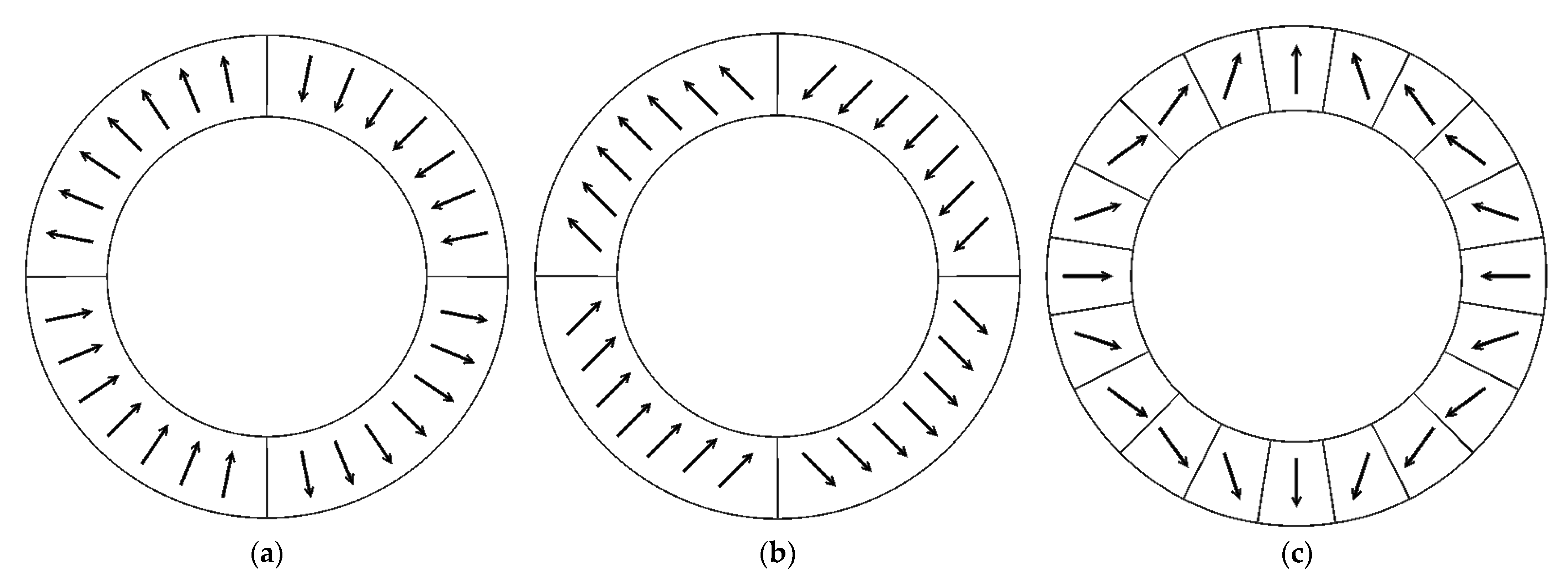
Figure 7.
PM magnetization methods. (a) Radial magnetization; (b) parallel magnetization; (c) Halbach magnetization.
Figure 7.
PM magnetization methods. (a) Radial magnetization; (b) parallel magnetization; (c) Halbach magnetization.
Figure 8.
Magnetic flux density and lines distributions of HSPMMs with different magnetization methods under no-load condition. (a) Radial magnetization; (b) parallel magnetization; (c) Halbach magnetization.
Figure 8.
Magnetic flux density and lines distributions of HSPMMs with different magnetization methods under no-load condition. (a) Radial magnetization; (b) parallel magnetization; (c) Halbach magnetization.
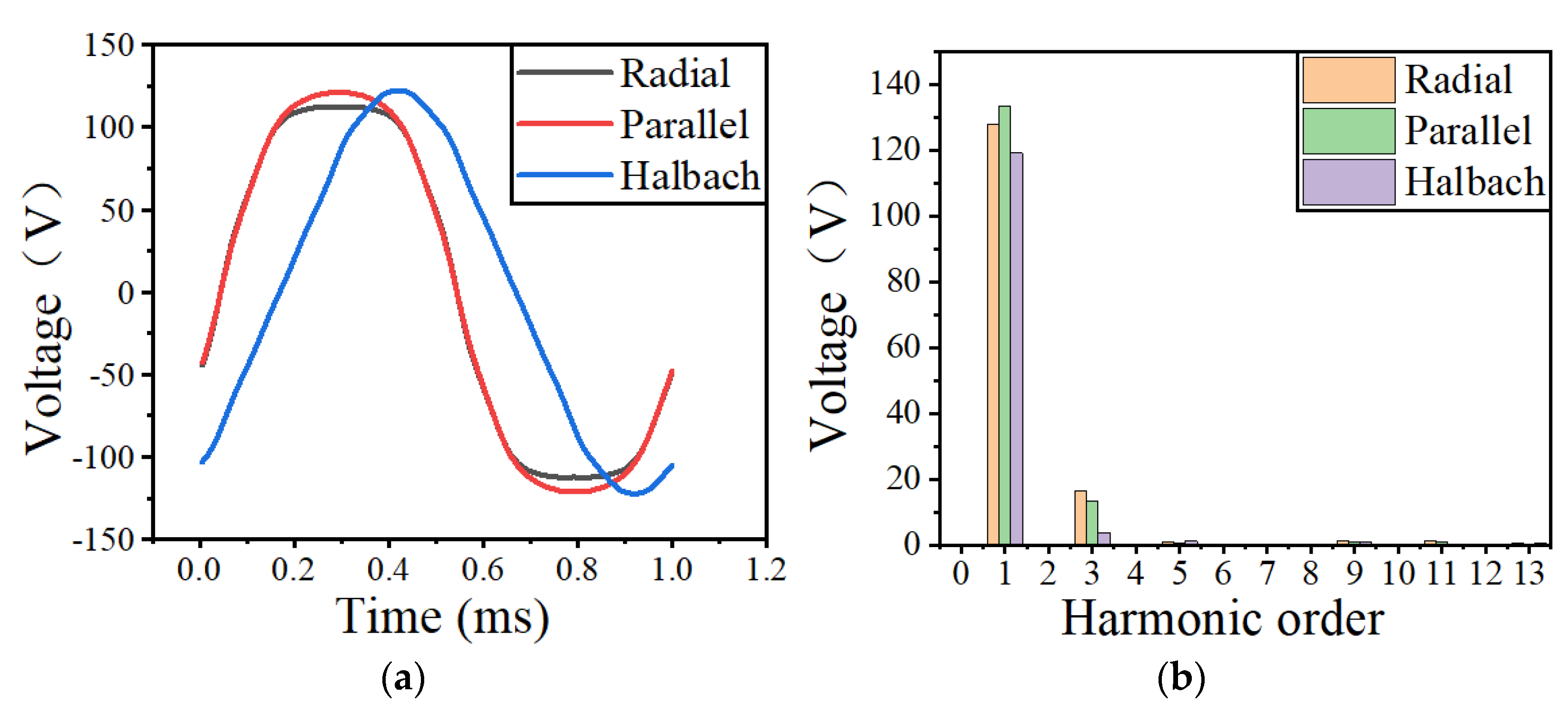
Figure 9.
Waveforms and FFT analysis results of back EMF for HSPMMs with different magnetization methods. (a) Waveforms; (b) FFT analysis results.
Figure 9.
Waveforms and FFT analysis results of back EMF for HSPMMs with different magnetization methods. (a) Waveforms; (b) FFT analysis results.
Figure 10.
Waveforms and FFT analysis results of air gap magnetic flux density for HSPMMs with different magnetization methods. (a) Waveforms; (b) FFT analysis results.
Figure 10.
Waveforms and FFT analysis results of air gap magnetic flux density for HSPMMs with different magnetization methods. (a) Waveforms; (b) FFT analysis results.
Figure 11.
The current and torque waveforms of the HSPMM under full-load conditions. (a) Current waveform; (b) torque waveform.
Figure 11.
The current and torque waveforms of the HSPMM under full-load conditions. (a) Current waveform; (b) torque waveform.
Figure 12.
Cooling channel structures. (a) Spiral structure; (b) axial structure 1; (c) axial structure 2.
Figure 12.
Cooling channel structures. (a) Spiral structure; (b) axial structure 1; (c) axial structure 2.
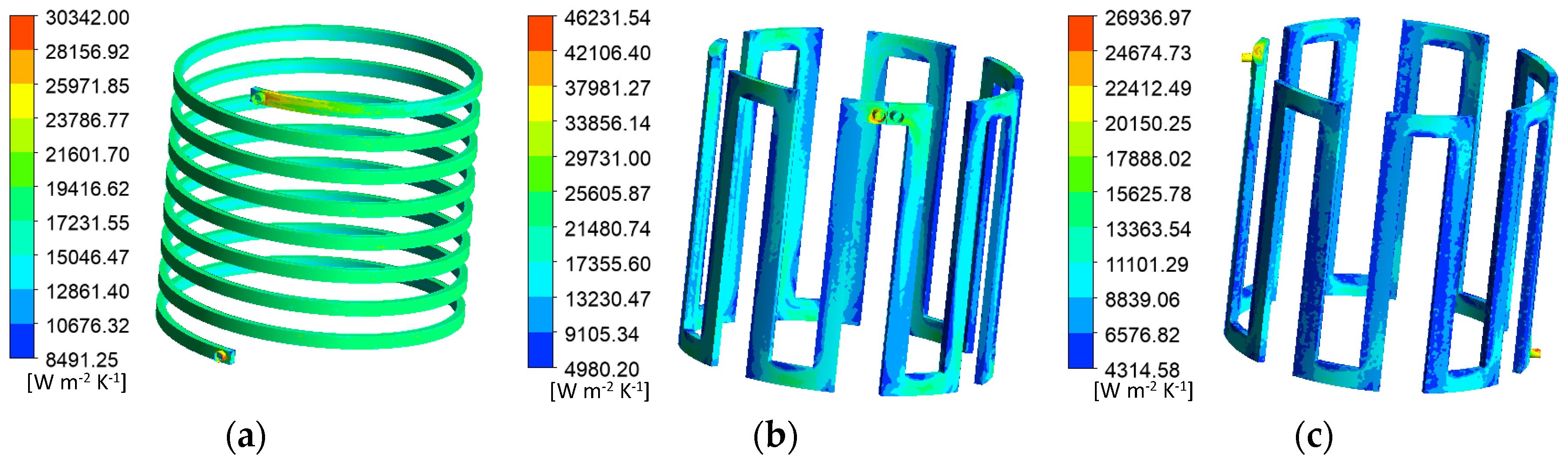
Figure 13.
Heat transfer coefficient distribution of the three cooling channel structures. (a) Spiral structure; (b) axial structure 1; (c) axial structure 2.
Figure 13.
Heat transfer coefficient distribution of the three cooling channel structures. (a) Spiral structure; (b) axial structure 1; (c) axial structure 2.
Figure 14.
Pressure distribution of the three cooling channel structures. (a) Spiral structure; (b) axial structure 1; (c) axial structure 2.
Figure 14.
Pressure distribution of the three cooling channel structures. (a) Spiral structure; (b) axial structure 1; (c) axial structure 2.
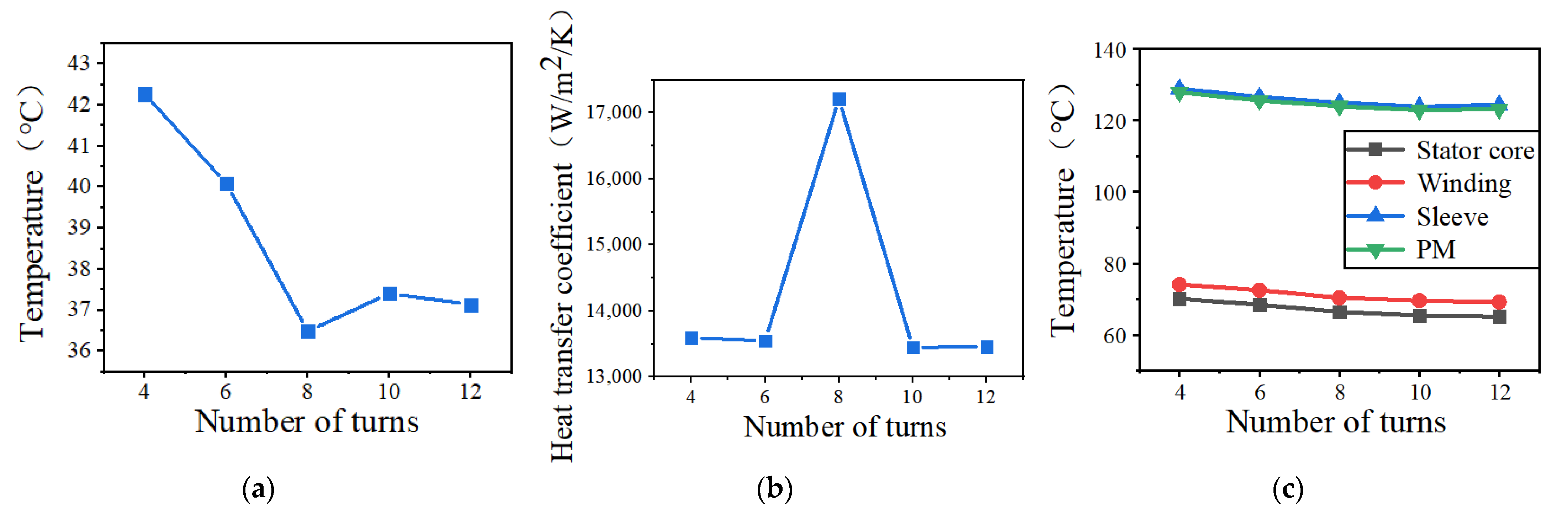
Figure 15.
Thermal analysis results of HSPMMs with different number of cooling channel turns. (a) Cooling water maximum temperature; (b) Heat transfer coefficient; (c) Motor maximum temperature.
Figure 15.
Thermal analysis results of HSPMMs with different number of cooling channel turns. (a) Cooling water maximum temperature; (b) Heat transfer coefficient; (c) Motor maximum temperature.
Figure 16.
Thermal analysis results of HSPMMs at different cooling water flow rates. (a) Cooling water maximum temperature; (b) heat transfer coefficient; (c) inlet pressure; (d) motor maximum temperature.
Figure 16.
Thermal analysis results of HSPMMs at different cooling water flow rates. (a) Cooling water maximum temperature; (b) heat transfer coefficient; (c) inlet pressure; (d) motor maximum temperature.
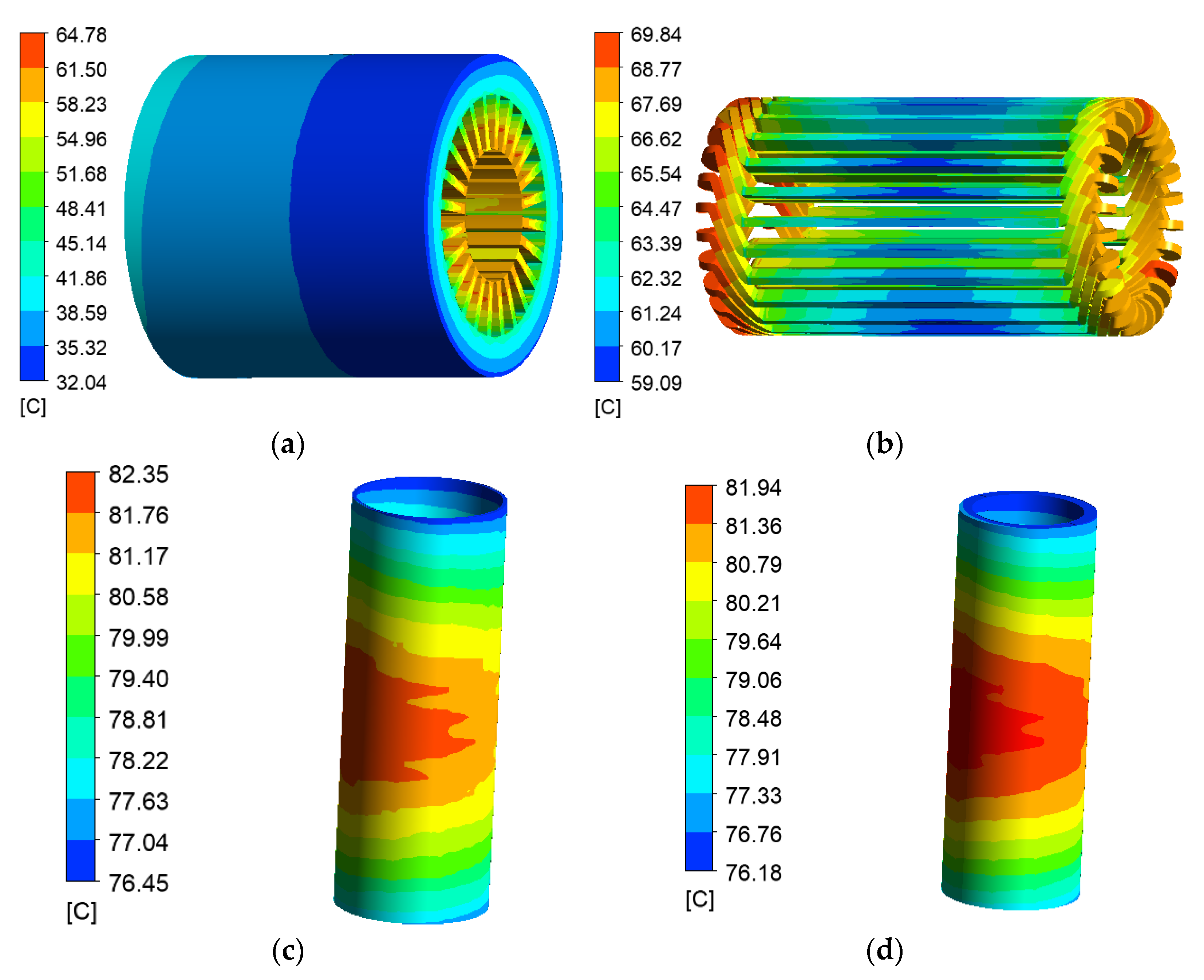
Figure 17.
Temperature distribution of the designed motor. (a) Stator; (b) winding; (c) sleeve; (d) PM.
Figure 17.
Temperature distribution of the designed motor. (a) Stator; (b) winding; (c) sleeve; (d) PM.
Figure 18.
Stress analysis model of the sleeve–PM–core–shaft structure rotor.
Figure 18.
Stress analysis model of the sleeve–PM–core–shaft structure rotor.
Figure 19.
Stress distribution of the sleeve–PM–core–shaft structure rotor. (a) PM radial stress; (b) PM tangential stress; (c) sleeve equivalent stress.
Figure 19.
Stress distribution of the sleeve–PM–core–shaft structure rotor. (a) PM radial stress; (b) PM tangential stress; (c) sleeve equivalent stress.
Figure 20.
The maximum stress of the rotor variations with sleeve thickness and interference. (a) PM maximum radial stress; (b) PM maximum tangential stress; (c) sleeve maximum equivalent stress.
Figure 20.
The maximum stress of the rotor variations with sleeve thickness and interference. (a) PM maximum radial stress; (b) PM maximum tangential stress; (c) sleeve maximum equivalent stress.
Figure 21.
The designed motor’s rotor stress distribution. (a) PM radial stress; (b) PM tangential stress; (c) sleeve equivalent stress.
Figure 21.
The designed motor’s rotor stress distribution. (a) PM radial stress; (b) PM tangential stress; (c) sleeve equivalent stress.
Table 1.
Calculation parameters of main dimensions of motor.
Table 1.
Calculation parameters of main dimensions of motor.
| Parameters | Value | Parameters | Value |
|---|
| P′ (kW) | 27 | A (A/m) | 50,000 |
| n (r/min) | 30,000 | Bδ (T) | 0.7 |
| αP′ | 0.7 | λ | 3 |
| Knm | 1.11 | P | 2 |
| Kdp | 0.92 | | |
Table 2.
Structural parameters of 2 and 4 poles HSPMMs.
Table 2.
Structural parameters of 2 and 4 poles HSPMMs.
| Parameters | 2 Poles | 4 Poles |
|---|
| Power (kW) | 30 | 30 |
| Speed (r/min) | 30,000 | 30,000 |
| Frequency (Hz) | 500 | 1000 |
| Stator outer diameter (mm) | 118 | 103 |
| Stator inner diameter (mm) | 45 | 45 |
| Slot number | 12 | 12 |
| Core length (mm) | 130 | 105 |
| Rotor outer diameter (mm) | 42.2 | 42.2 |
| Number of winding turns | 7 | 8 |
| Winding pitch | 5 | 2 |
Table 3.
Performances of 2 and 4 poles HSPMMs under full-load condition.
Table 3.
Performances of 2 and 4 poles HSPMMs under full-load condition.
| Parameters | 2 Poles | 4 Poles |
|---|
| RMS current (A) | 117.10 | 117.28 |
| Torque (N·m) | 9.48 | 9.49 |
| Torque ripple (%) | 5.32 | 13.84 |
| Stator iron loss (W) | 321.43 | 558.68 |
| Winding copper loss (W) | 257.22 | 264.09 |
| Rotor eddy current loss (W) | 218.19 | 210.48 |
| Wind friction loss (W) | 72.53 | 58.58 |
| Efficiency (%) | 97.10 | 96.36 |
Table 4.
Performances of 12 slots, 18 slots and 24 slots HSPMMs under full-load condition.
Table 4.
Performances of 12 slots, 18 slots and 24 slots HSPMMs under full-load condition.
| Parameters | 12 Slots | 18 Slots | 24 Slots |
|---|
| RMS current (A) | 117.28 | 114.61 | 108.59 |
| Torque (N·m) | 9.49 | 9.54 | 9.54 |
| Torque ripple (%) | 13.84 | 5.05 | 2.95 |
| Stator iron loss (W) | 558.68 | 554.87 | 558.81 |
| Winding copper loss (W) | 264.09 | 225.73 | 244.81 |
| Rotor eddy current loss (W) | 210.48 | 47.15 | 21.22 |
| Wind friction loss (W) | 58.58 | 58.58 | 58.58 |
| Efficiency (%) | 96.36 | 97.05 | 97.06 |
Table 5.
Performances of the three HSPMMs with different PM magnetization methods under full-load condition.
Table 5.
Performances of the three HSPMMs with different PM magnetization methods under full-load condition.
| Parameters | Radial | Parallel | Halbach |
|---|
| RMS current (A) | 110.89 | 106.15 | 119.02 |
| Torque (N·m) | 9.55 | 9.56 | 9.55 |
| Torque ripple (%) | 2.07 | 1.42 | 1.99 |
| Stator iron loss (W) | 511.09 | 478.63 | 437.87 |
| Winding copper loss (W) | 303.32 | 273.81 | 378.37 |
| Rotor eddy current loss (W) | 11.84 | 10.23 | 11.37 |
| Wind friction loss (W) | 33.16 | 33.16 | 33.16 |
| Efficiency (%) | 97.22 | 97.42 | 97.21 |
Table 6.
Structure and electromagnetic parameters of the 30 kW, 30,000 r/min HSPMM.
Table 6.
Structure and electromagnetic parameters of the 30 kW, 30,000 r/min HSPMM.
| Parameters | Value | Parameters | Value |
|---|
| Power (kW) | 30 | Pole number | 4 |
| Speed (r/min) | 30000 | Slot number | 24 |
| Frequency (Hz) | 1000 | Stator outer diameter (mm) | 100 |
| RMS current (A) | 106.15 | Stator inner diameter (mm) | 41 |
| Torque (N·m) | 9.56 | Core length (mm) | 103 |
| Torque ripple (%) | 1.42 | Air gap thickness (mm) | 1.5 |
| Stator iron loss (W) | 478.63 | Rotor outer diameter (mm) | 38 |
| Winding copper loss (W) | 273.81 | Sleeve thickness (mm) | 1 |
| Rotor eddy current loss (W) | 10.23 | PM material | NdFeB |
| Wind friction loss (W) | 33.16 | PM thickness (mm) | 3.4 |
| Efficiency (%) | 97.42 | Magnetization direction | Parallel |
Table 7.
The maximum temperature of each part of motors with different cooling channel structures.
Table 7.
The maximum temperature of each part of motors with different cooling channel structures.
| Parameters | Spiral | Axial 1 | Axial 2 |
|---|
| Cooling water (°C) | 36.49 | 38.67 | 44.53 |
| Stator core (°C) | 66.08 | 66.63 | 68.80 |
| Stator winding (°C) | 69.96 | 70.84 | 73.99 |
| Sleeve (°C) | 124.89 | 125.01 | 131.91 |
| PM (°C) | 124.81 | 124.92 | 131.79 |


