
Design of Moiré-Inspired Metasurface Lens for Focusing Electromagnetic Power in Fresnel Near-Field Region


Abstract
:
1. Introduction
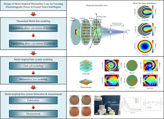
2. Moiré-Inspired MSL System
2.1. Theoretical Background: Moiré Lens
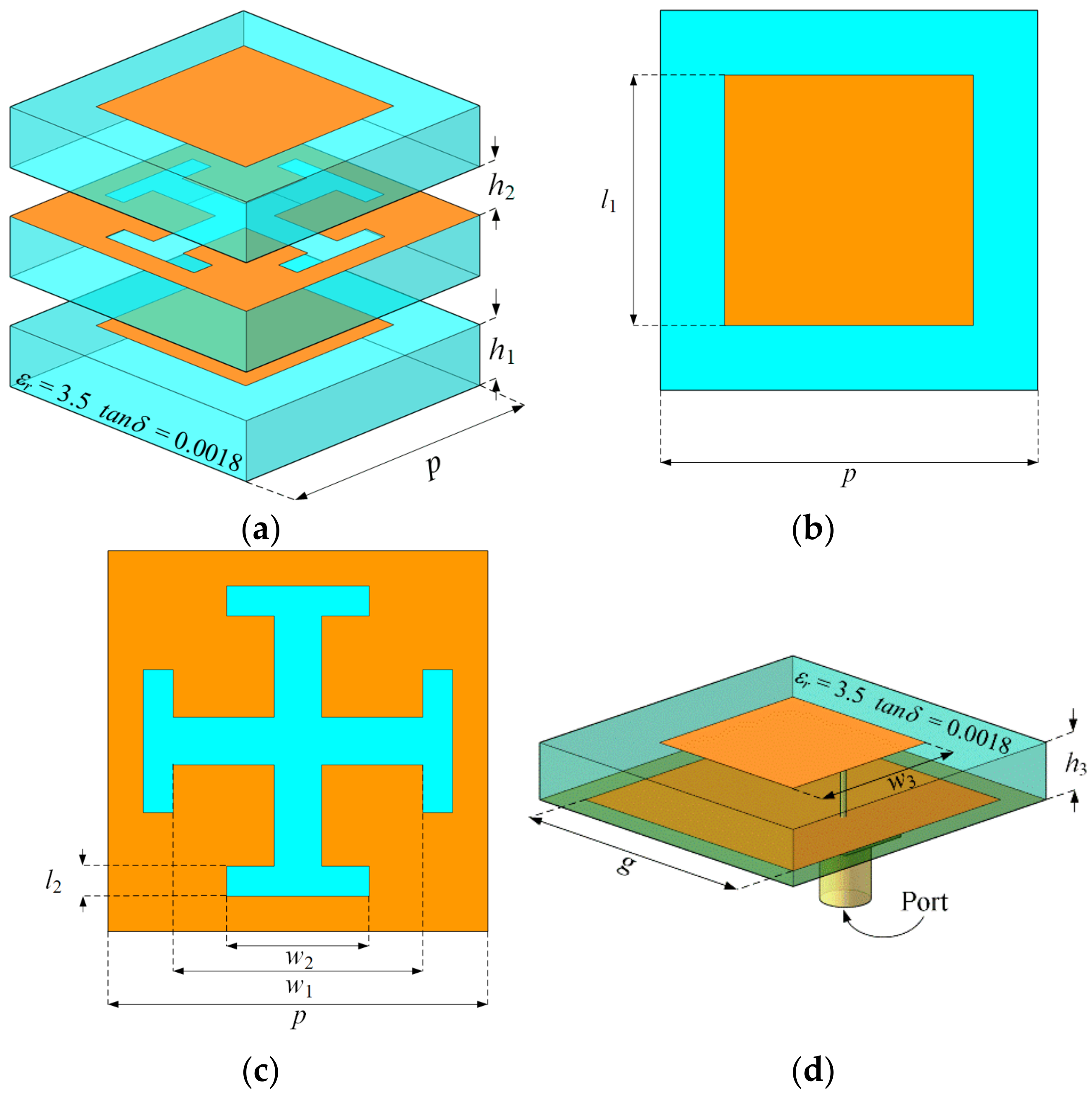
2.2. Design of Moiré MSL System
3. Fabrication and Measurement
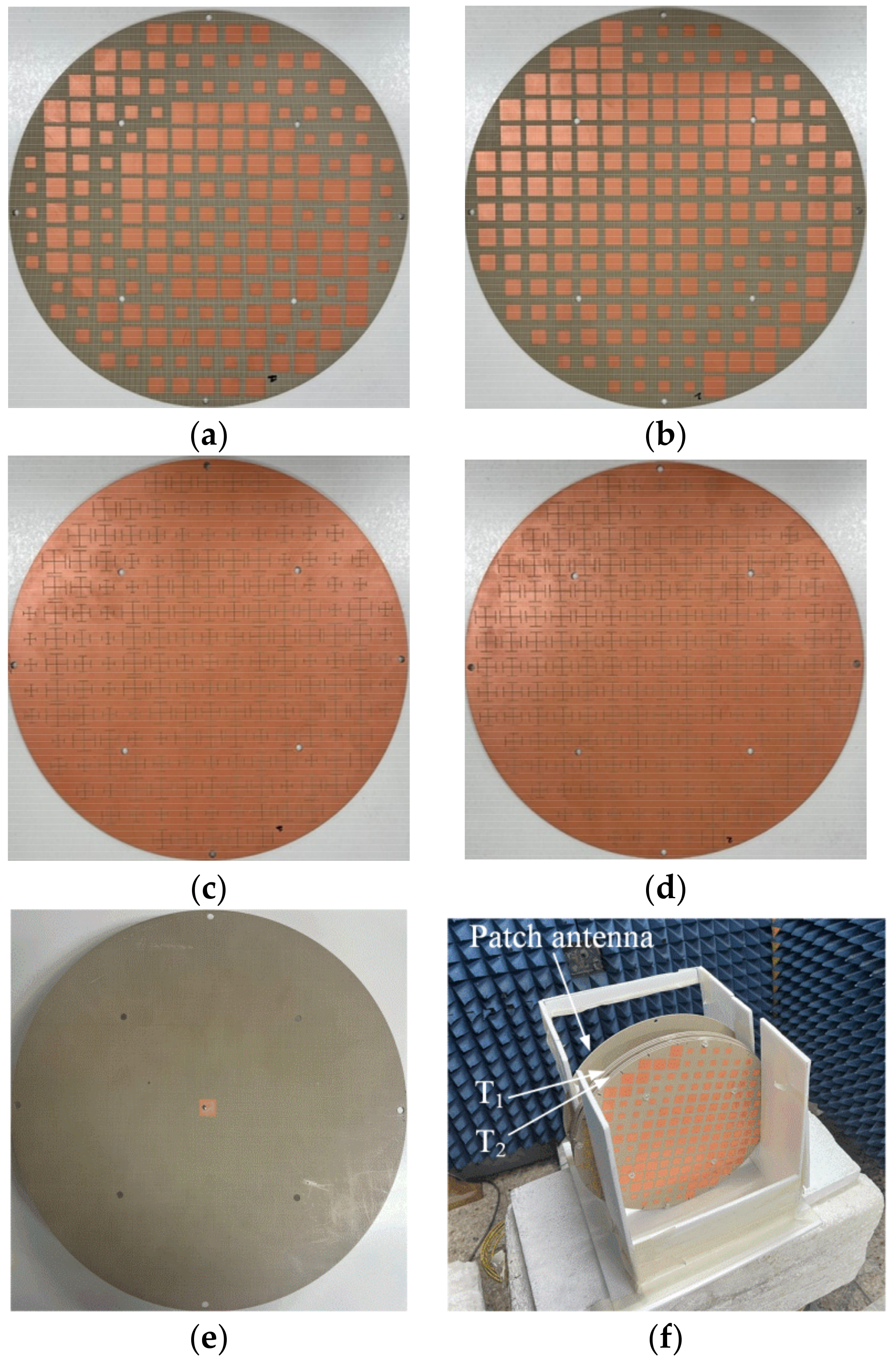
3.1. Moiré-Inspired MSL System Fabrication
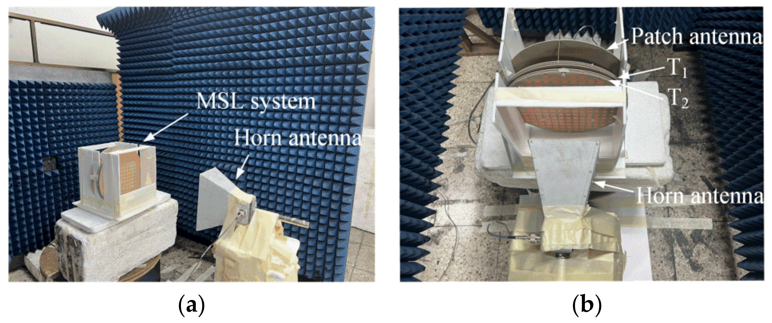
3.2. Moiré-Inspired MSL System Measurement
4. Conclusions
Author Contributions
Funding
Institutional Review Board Statement
Informed Consent Statement
Data Availability Statement
Conflicts of Interest
References
- Siragusa, R.; Lemaire-Auger, P.; Tedjini, S. Tunable near-field focused circular phase-array antenna for 5.8-GHz RFID applications. IEEE Antennas Wirel. Propag. Lett. 2011, 10, 33–36. [Google Scholar] [CrossRef]
- Gowda, V.R.; Yurduseven, O.; Lipworth, G.; Zupan, T.; Reynolds, M.S.; Smith, D.R. Wireless power transfer in the radiative near field. IEEE Antennas Wirel. Propag. Lett. 2016, 15, 1865–1868. [Google Scholar] [CrossRef]
- Kim, G.; Lee, B. Design of wireless power and information transfer systems considering figure of merit for information. J. Electromagn. Eng. Sci. 2020, 20, 241–247. [Google Scholar] [CrossRef]
- Kang, E.; Hur, J.; Seo, C.; Lee, H.; Choo, H. High aperture efficiency array antenna for wireless power transfer applications. Energies 2020, 13, 2241. [Google Scholar] [CrossRef]
- Ahmad, Z.; Wang, Z.; Jaffri, Z.U.A.; Bao, S. Accurate theoretical models for frequency diverse array based wireless power transmission. Energies 2022, 15, 1588. [Google Scholar] [CrossRef]
- Shan, L.; Geyi, W. Optimal design of focused antenna arrays. IEEE Trans. Antennas Propag. 2014, 62, 5565–5571. [Google Scholar] [CrossRef]
- Liu, Y.; Cheng, Q.; Khan, A.N.; Giddens, H.; Torrico, M.M.; Hao, Y. Low-profile beam steerable patch array with SIW feeding network. IEEE Access 2020, 8, 164178. [Google Scholar] [CrossRef]
- Li, M.; Chang, K. Novel low-cost beam-steering techniques using microstrip patch antenna arrays fed by dielectric image lines. IEEE Trans. Antennas Propag. 1999, 47, 453–457. [Google Scholar] [CrossRef]
- Hansen, R.C. Focal region characteristics of focused array antennas. IEEE Trans. Antennas Propag. 1985, 33, 1328–1337. [Google Scholar] [CrossRef]
- Nikfalazar, M.; Kohler, C.; Wiens, A.; Mehmood, A.; Sohrabi, M.; Maune, H.; Binder, J.R.; Jakoby, R. Beam steering phased array antenna with fully printed phase shifters based on low-temperature sintered BST-composite thick films. IEEE Microw. Wirel. Compon. Lett. 2016, 26, 70–73. [Google Scholar] [CrossRef]
- Rana, B.; Lee, I.-G.; Hong, I.-P. Experimental characterization of 2 × 2 electronically reconfigurable 1bit unit cells for a beamforming transmitarray at x band. J. Electromagn. Eng. Sci. 2021, 21, 153–160. [Google Scholar] [CrossRef]
- Hu, J.; Li, Y.; Zhang, Z. A novel reconfigurable miniaturized phase shifter for 2-D beam steering 2-bit array applications. IEEE Microw. Wirel. Compon. Lett. 2021, 31, 381–384. [Google Scholar] [CrossRef]
- Sheikh, S.I.M.; Gibson, A.A.P.; Basorrah, M.; Alhulwah, G.; Alanizi, K.; Alfarsi, M.; Zafar, J. Analog/digital ferrite phase shifter for phased array antennas. IEEE Antennas Wirel. Propag. Lett. 2010, 9, 319–321. [Google Scholar] [CrossRef]
- Lim, T.-H.; Seo, C.; Choo, H. Design of a metasurface lens to adjust the focal length for near-field beam focusing. J. Korean Inst. Electromagn. Eng. Sci. 2021, 32, 610–615. [Google Scholar] [CrossRef]
- Xue, C.; Lou, Q.; Chen, Z.N. Broadband double-layered Huygens’ metasurface lens antenna for 5G millimeter-wave systems. IEEE Trans. Antennas Propag. 2020, 68, 1468–1476. [Google Scholar] [CrossRef]
- Pfeiffer, C.; Grbic, A. Planar lens antennas of subwavelength thickness: Collimating leaky-waves with metasurfaces. IEEE Trans. Antennas Propag. 2015, 63, 3248–3253. [Google Scholar] [CrossRef]
- Xu, R.; Chen, Z.N. A compact beamsteering metasurface lens array antenna with low-cost phased array. IEEE Trans. Antennas Propag. 2021, 69, 1992–2002. [Google Scholar] [CrossRef]
- Altair. FEKO. Available online: www.altair.com (accessed on 29 March 2022).
- Liu, Z.; Du, Z.; Hu, B.; Liu, W.; Liu, J.; Wang, Y. Wide-angle Moiré metalens with continuous zooming. J. Opt. Soc. Am. B 2019, 36, 2810–2816. [Google Scholar] [CrossRef]
- Bernet, S.; Harm, W.; Ritsch-Marte, M. Demonstration of focus-tunable diffractive Moiré-lenses. Opt. Express 2013, 21, 6955–6966. [Google Scholar] [CrossRef] [PubMed]
- Lee, J.G. Tutorial: Reconfigurable transmitarray antenna using metasurface. J. Korean Inst. Electromagn. Eng. Sci. 2020, 31, 663–676. [Google Scholar] [CrossRef]
- Oster, G.; Nishijima, Y. Moiré patterns. Sci. Am. 1963, 208, 55–63. [Google Scholar] [CrossRef]
- Oster, G.; Wasserman, M.; Zwerling, C. Theoretical interpretation of Moiré patterns. J. Opt. Soc. Am. 1964, 54, 169–175. [Google Scholar] [CrossRef]
- Bernet, S.; Ritsch-Marte, M. Adjustable refractive power from diffractive moiré elements. Appl. Opt. 2008, 47, 3722–3730. [Google Scholar] [CrossRef]
- Li, M.-Y.; Ban, Y.-L.; Yan, F.-Q. Wideband low-profile Ku-band transmitarray antenna. IEEE Access 2020, 9, 6683–6688. [Google Scholar] [CrossRef]
- Iwami, K.; Ogawa, C.; Nagase, T.; Ikezawa, S. Demonstration of focal length tuning by rotational varifocal moiré metalens in an ir-A wavelength. Opt. Express 2020, 28, 35602–35614. [Google Scholar] [CrossRef] [PubMed]
- Balanis, C.A. Antenna Theory: Analysis and Design, 4th ed.; Wiley: Hoboken, NJ, USA, 2016. [Google Scholar]


| Parameters | Values (mm) | Parameters | Values (mm) |
|---|---|---|---|
| p | 51.7 | l2 | 0.4 |
| h1 | 1.56 | w1 | 7–18 |
| h2 | 1.56 | w2 | 1.9–12.9 |
| h3 | 1.56 | w3 | 12.8 |
| l1 | 7–18 | g | 40 |
Publisher’s Note: MDPI stays neutral with regard to jurisdictional claims in published maps and institutional affiliations. |
© 2022 by the authors. Licensee MDPI, Basel, Switzerland. This article is an open access article distributed under the terms and conditions of the Creative Commons Attribution (CC BY) license (https://creativecommons.org/licenses/by/4.0/).
Share and Cite
Lim, T.-H.; Kim, H.; Seo, C.; Choo, H. Design of Moiré-Inspired Metasurface Lens for Focusing Electromagnetic Power in Fresnel Near-Field Region. Energies 2022, 15, 3911. https://doi.org/10.3390/en15113911
Lim T-H, Kim H, Seo C, Choo H. Design of Moiré-Inspired Metasurface Lens for Focusing Electromagnetic Power in Fresnel Near-Field Region. Energies. 2022; 15(11):3911. https://doi.org/10.3390/en15113911
Chicago/Turabian StyleLim, Tae-Heung, Hyunsoo Kim, Chulhun Seo, and Hosung Choo. 2022. "Design of Moiré-Inspired Metasurface Lens for Focusing Electromagnetic Power in Fresnel Near-Field Region" Energies 15, no. 11: 3911. https://doi.org/10.3390/en15113911