Article

Position Estimation of Multiple Receiving Coils and Power Transmission Control for WPT without Feedback

1
Department of AI Convergence Network, Ajou University, Suwon 16499, Republic of Korea
2
Electronics and Telecommunications Research Institute, Daejeon 34129, Republic of Korea
3
Department of Electrical and Computer Engineering, Ajou University, Suwon 16499, Republic of Korea
*
Author to whom correspondence should be addressed.
Energies 2022, 15(22), 8621; https://doi.org/10.3390/en15228621
Submission received: 28 October 2022 / Revised: 14 November 2022 / Accepted: 15 November 2022 / Published: 17 November 2022
(This article belongs to the Special Issue Next Generation Wireless Charging System for Mobile Devices)

Abstract

:
It is important to determine the position of the receiver (Rx) coils in wireless power transfer (WPT) system, and to control the power transmitted to the Rx coil based on this result. In particular, in a situation where there is no feedback between the primary side and the secondary side, it is difficult to control the received power because the information is limited. In this paper, a method for determining the position of the Rx coils and controlling the received power using limited parameters in a feedback-free WPT system is proposed. The proposed method is verified by constructing a 4 × 2 WPT system, and it is validated that the simulation result and the experimental result are consistent well. Furthermore, arbitrary power can be transmitted to the Rx coil based on the result of the position of the Rx coil. The experiment is conducted by transmitting about 1 W to Rx 1 and Rx 2, and the efficiency for Rx 1 is about 32.93 % , Rx 2 is 25.03 % , and the overall efficiency is confirmed to be 57.96 % .

1. Introduction

Wireless power transfer (WPT) is a novel method that can transmit power to devices without a wire connection. Recently, WPT systems have been applied in various fields such as unmanned aerial vehicle (UAV), electric vehicle (EV), drone, medical devices, and mobile devices [1,2,3,4,5,6]. In the early introduction of the WPT, a simple system using a single transmitter (Tx), and receiver (Rx) coil was studied for charging one device [7]. However, the single coil system was vulnerable to misalignment between the coils, so the performance was clearly limited. Therefore, it was necessary to design a system that can take these problems into account, and a system using multiple Tx coils was devised as a solution for misalignment [8,9]. In [8], an impedance matching method for improving power efficiency in lateral misalignment conditions was proposed, and the results were confirmed using two Tx coils. In [9], study for coil design and hardware were conducted using seven Tx coils to improve efficiency in a misalignment condition. Recently, the number of devices that need to be charged in daily life is increasing. Accordingly, there is a need to charge multiple devices at the same time, which is why studies on a WPT system for multiple Rx coils become important.
In order to charge multiple Rx coils simultaneously, it is necessary to estimate the mutual inductance between the Tx coils and each Rx coil, and a method to control the primary side is required. According to recent studies, the mutual inductance or coupling coefficient between the Tx coils and the Rx coils must be estimated in order to calculate the impedance of the coils, calculate the received power, and operate the algorithms for controlling Tx coils [10,11,12]. The mutual inductance can be calculated using measurement or EM simulation. These methods may be suitable for verifying their idea. However, in order to calculate mutual inductance using measurement, system for measuring the current on both the primary side and the secondary side is needed, and the result must be fed back to the controller in charge of the calculation. Adding such a system may unnecessarily increase the complexity and the cost of the total WPT system. Therefore, it is necessary to study a method for controlling the primary side by sensing the existence of the Rx coils without any feedback from secondary side.
Assuming no feedback, parameters related to the Rx coil (i.e., impedance, mutual inductance) cannot be obtained at the primary side at all. In order to transmit power under these condition, two difficulties are encountered. First, there is a need for a method for determining where the Rx coils are and how many there are. Therefore, the method for determining position of Rx coils using only information that can be obtained from the primary side is needed. For estimating Rx coil position this purpose, there are previous studies such as adding an additional coil for position detection or using a sensor [13,14,15,16,17,18,19]. These methods obviously have limitations in the situation where the feedback is absent, and increase the overall cost and complexity of the system. In addition, the study of moving Rx itself in [19] has a limitation that it cannot be applied to environments where the Rx coil is static, such as mobile devices or medical implant. These studies are conducted on a single Rx coil, which needs to be extended to determining the position for multiple Rx coils. As another method, studies have been conducted using measurements [20,21,22]. In [20], the experiment was conducted by placing several Tx coils on a plane, and the position of the Rx coil is determined by measuring the coupling coefficients between the Tx and Rx coils. This method requires additional settings to measure coupling, which adds cost and effort to the whole process for WPT. In [21,22], the measurement on the primary side is used for estimating Rx coil position, but there is a limitation that it can be applied to only one Rx coil. Without adding any special sensor or measurement setup, studies on position estimating multiple Rx coils are clearly needed but still insufficient. Second, in order to transmit the desired power to the Rx coil, the Tx coil control algorithm must be simple. As in algorithm studies for multiple Rx coils, a complex calculation method is used for their system [23,24]. However, without feedback, there are few parameters available, so the more complex the algorithm, the less likely it is working well. In other words, it is important to study a simple method that can determine the position of multiple Rx coils and use the results to control power transmission.
In this paper, the eigenvalue and eigenvector of parameter that can be calculated by Tx coils are analyzed to determine which Tx coils are aligned with the Rx coil. Then, we propose a simple solution to control the Tx coils assigned to each Rx coil. To validate proposed method, EM simulation model with 64 × 2 coils is used and the measurement is carried out by a 4 × 2 magnetic resonant WPT system [25]. This paper is organized as follows. In Section 2, the WPT equivalent circuit is analyzed and provides the basic equations with the multiple Tx and Rx coils. In Section 3, proposed method for estimating position of Rx coils and power control method without feedback is analyzed theoretically and the simulation results are represented. In Section 4, measurement setup is showed and the experimental results are discussed. Section 5 is the conclusion.

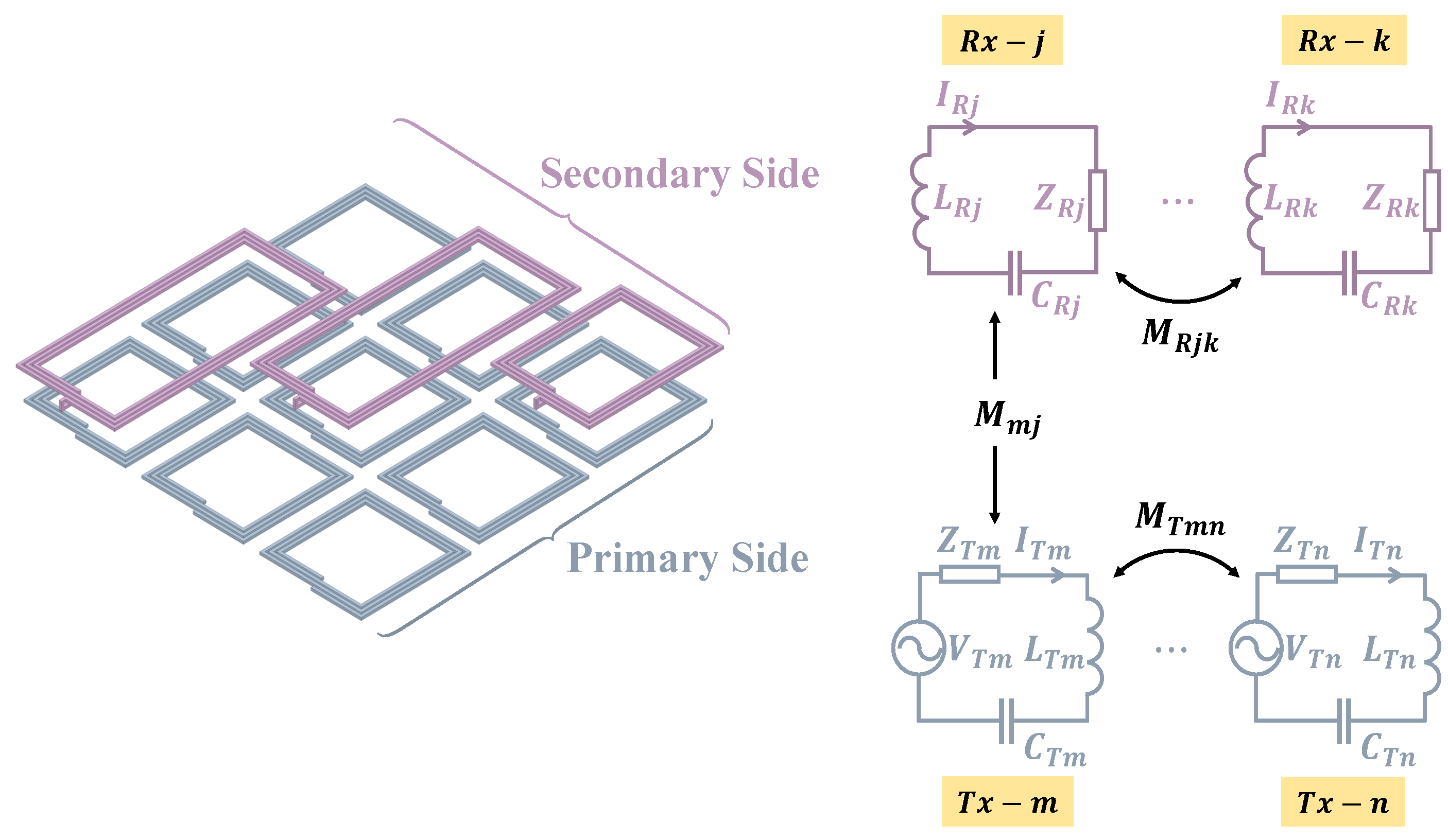
2. WPT Equivalent Circuit Equation

The magnetic resonant WPT system is equivalent with an LC circuit by connecting a matching capacitor for the resonance of the coil. That is j ω L T x + 1 / j ω C T x = 0 for Tx coil, and j ω L R x + 1 / j ω C R x = 0 for Rx coil, where L T x ( L R x ) and C T x ( C R x ) denote the self inductance and capacitance for Tx and Rx coil, and ω means a resonant frequency in which Tx and Rx coils are tuned. Figure 1 shows the self-resonant WPT system composed of n Tx coils and k Rx coils.
The equivalent circuit of magnetic resonant WPT system with n × k coils can be expressed as following:
Z R j I R j + v j j ω M R j v I R v from the other Rx coils = m j ω M m j I T m from the Tx coils
V T m = Z T m I T m + n m j ω M T m n I T n from the other Tx coils j j ω M m j I R j from the Rx coils
where V, I, and Z are the AC voltage, current and impedance, respectively. The subscripts T and R mean the Tx and Rx coil. M T , M R , and M mean the mutual inductance between Tx–Tx, Rx–Rx, Tx–Rx, respectively. The above Equations (1) and (2) can be represented as matrix operation as follows:
i R 1 i R k i R = j ω Z R 1 j ω M R 12 j ω M R 1 k j ω M R 21 Z R 2 j ω M R 2 k j ω M R k 1 j ω M R k 2 Z R k Z R 1 1 M 11 M 21 M n 1 M 1 k M 2 k M n k M i T 1 i T n i T = H i T
v T 1 v T n V T = Z T 1 j ω M T 12 j ω M T 1 n j ω M T 21 Z T 2 j ω M T 2 n j ω M T n 1 j ω M T n 2 Z T n Z T + ω 2 M T Z R 1 M i T = Z T + Ψ i T

3. Principles of the Proposed Method

3.1. Theoretical Analysis of the Proposed Method

Determining the position of the Rx coils means figuring out how much influence the Tx coils can have on the Rx coil. That is, the Tx coils close to the Rx coil can have a large influence on that Rx coil. The influence is defined as the mutual inductance between Tx and Rx coils M . However, if the impedance and current of the Rx coils are not known, the exact value of the mutual inductance cannot be estimated. Therefore, there is a need for a parameter that can be used instead of it. First, the Tx coil impedance Z T can determined using only Tx coils. Z T is composed of the impedance of the Tx coils and the mutual inductance between the Tx coils, and is a fixed value determined after the coils are manufactured and placed. After the position of the Tx coils is fixed, arbitrary voltage vectors are applied as many as the number of Tx coils. Then, the currents flowing through the Tx coils are measured, and Z T is calculated as follows:
Z T = v T ( 1 ) , , v T ( n ) i T ( 1 ) , , i T ( n ) 1
Each of the vectors v T in Equation (5) must be independent of each other. In other words, the rank of the matrix v T ( 1 ) , , v T ( n ) must be equal to the number of Tx coils. After calculating Z T , the Tx coils are able to control completely using Equation (4) with Ψ = 0 .
After calculating Z T , if the Tx coil is operated in the sequence of v T = 1 , 0 , , 0 T , 0 , 1 , , 0 T , , 0 , 0 , , 1 T or any voltage sets, the current flow of Tx coils can be predicted. When the Rx coil is entered in the charging space, Ψ has a non-zero value and the current flowing through the Tx coils is changed according to Equation (4). That is, if the current of the Tx coil is continuously sensed, it is possible to know whether there is a Rx coil or not. When it is determined that the Rx coil is appeared, the similar process as in Equation (5) is repeated and Ψ can calculated as follows:
Ψ = v T ( 1 ) , , v T ( n ) i T ( 1 ) , , i T ( n ) 1 Z T
By taking the real part of the calculated Ψ , a parameter H H R R H can be obtained [24]. The superscript H means conjugate transpose, and R R = r e a l ( Z R ) . Because H H R R H is positive semi-definite matrix, it has positive and real eigenvalues. If there is only one Rx coil, H H R R H becomes proportional to M T M as follows:
H H R R H = ω 2 R R x M T M
The M T M has a characteristic that its eigenvector corresponding to the largest eigenvalue is proportional to the mutual inductance M . That is, if the eigenvector corresponding to the largest eigenvalue of H H R R H is found, the Tx coils having a large mutual inductance with Rx coil can be detected. That means the position of Rx coil can be detectable only using primary side. However, the eigenvector no longer matches the mutual inductance M when the number of Rx coils becomes two or more. This is because H H R R H is not proportional to M T M as shown in the following equation.
H H R R H = ω 2 M T ( Z R 1 ) H R R Z R 1 M
For two or more Rx coils, the position of the Rx coils can be determined in a slightly different way by using the characteristics of H H R R H . Let H H R R H ( T o t a l ) be calculated using Equation (6) for two or more Rx coils. If ω 2 M R i j 2 0 , H H R R H ( T o t a l ) has a characteristic that it is composed of the sum of H H R R H ( R x i ) when only each Rx coil exists. That is, if the mutual inductance between the Rx coils is negligible, the following equation is established.
H H R R H ( T o t a l ) i H H R R H ( R x i ) ( i k )
In practice, the value of the mutual inductance between the Rx coils is negligible unless they are specifically overlapped or faced each other. Therefore, Equation (9) works well for estimating the H H R R H ( R x i ) corresponding to each Rx coil. After that, the position of the Rx coil can be determined by analyzing the eigenvalue and eigenvector of H H R R H ( R x i ) .
When the position of Rx coils is determined, it is possible to know which Tx coil is optimal for transmitting power to each Rx coil. Operating the optimized Tx coils for each Rx coil means that multiple input multiple output (MIMO) WPT system is divided into several multiple input single output (MISO) systems. In this study, [26,27], the method of controlling the received power in the MISO WPT system is analyzed by applying the Tx coil current with a ratio of the mutual inductance M . In this regard, the proposed method is to first analyze the eigenvalues and eigenvectors of H H R R H ( R x i ) using Equation (9). Then, it is possible to obtain an eigenvector proportional to the mutual inductance M , and control the received power by calculating the Tx coil current with the sum of the eigenvectors of the H H R R H ( R x i ) . That is, it means finding a solution that allows the Tx coils to focus power only on the Rx coil allocated to it. The received power under the condition ω 2 M R i j 2 0 is as follows:
P R = i R H R R i R = i T H H H R R H ( T o t a l ) i T i i T H H H R R H ( R x i ) i T ( i k )
In order to transmit the required power P R , the current i T is determined as follows:
i T = c 1 · i T 1 , c 2 · i T 2 , , c n · i T n T
i T i = 0 , if no Rx coil on i-th Tx coil i-th row of m a x e i g ( H H R R H ( R x j ) ) , if j-th Rx coil on i-th Tx coil
where c is scaling factor, and maxeig means the eigenvector corresponding to the largest eigenvalue.

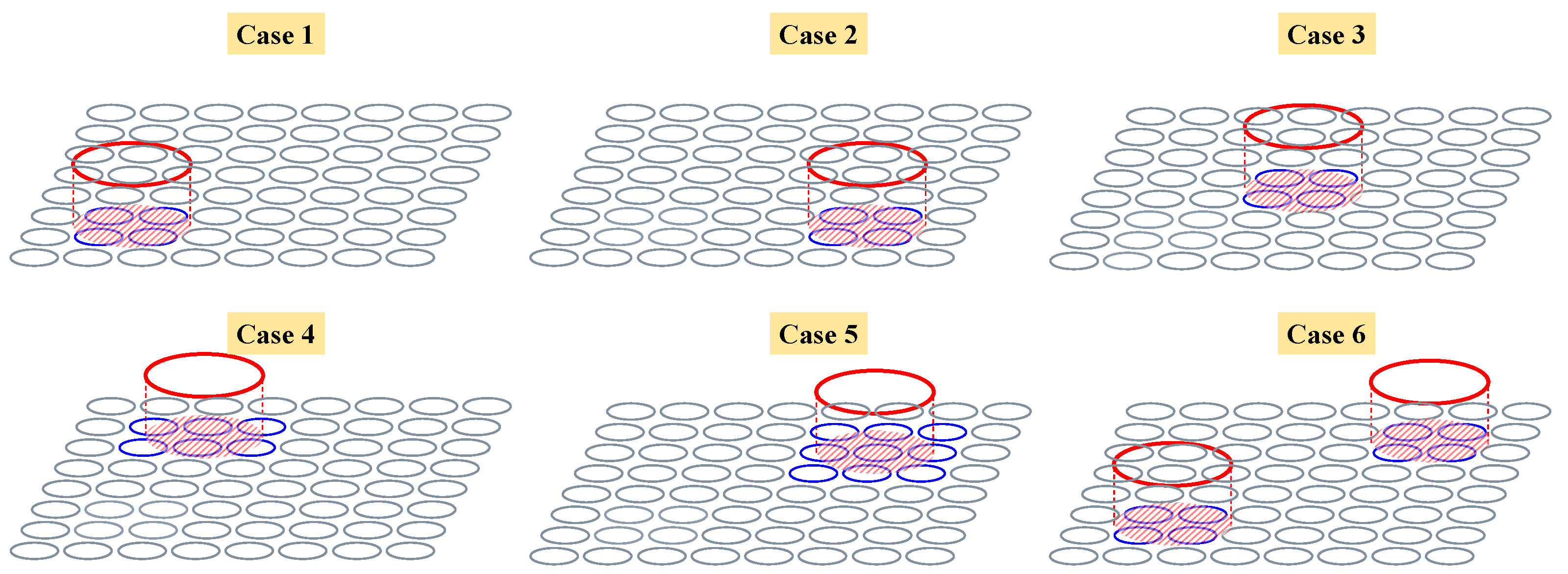
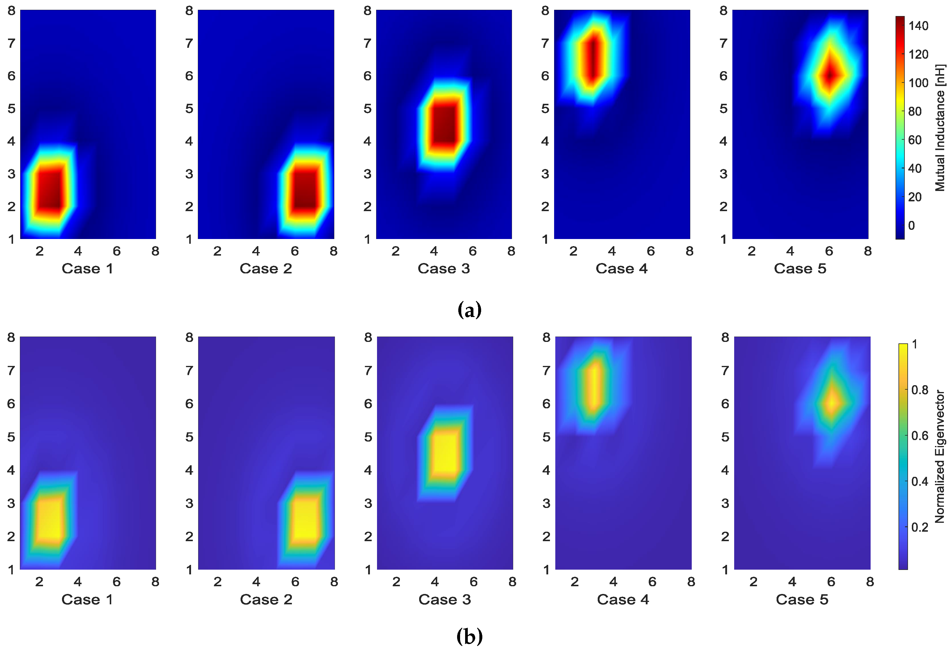
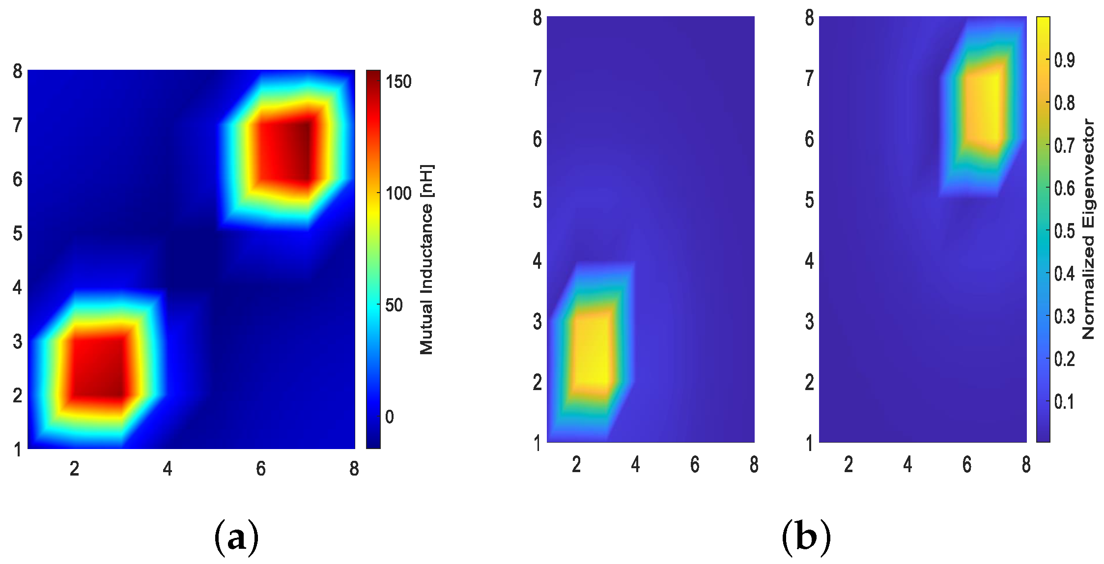
3.2. Simulation and Results

For the verification of the proposed method for determining the position of the Rx coils, 64 Tx coils are modeled in a plane using EM simulator. Tx coils are arranged in the form of 8 × 8 , and Rx coils with a larger diameter than the Tx coils are placed in an arbitrary position for simulation. The arrangement of the coils and the five points are shown in Figure 2.
In cases 1 to 5, one Rx coil is placed 5 cm above the Tx coils, and the position is arbitrarily changed. In cases 1 to 3, the Rx coil is placed at arbitrary position covered the 4 Tx coils arranged in 2 × 2. In cases 4 and 5, the Rx coils covered 6 and 9 Tx coils, respectively, and are placed in a position where they overlapped half or very little with some Tx coils. In case 6, two Rx coils are placed at the same height above the Tx coils. Then, mutual inductance M can be analyzed for each case using EM simulator. Since H is defined as in Equation (3), if Z R is fixed, H H R R H ( R x i ) can be calculated. Figure 3 shows the distribution of the mutual inductance M and the magnitude of the eigenvector corresponding to the largest eigenvalue of the H H R R H ( R x i ) . In order to confirm the result for the two Rx coils in case 6, H H R R H ( R x 1 ) is calculated first using Equation (6), and H H R R H ( R x 2 ) is obtained with H H R R H ( T o t a l ) H H R R H ( R x 1 ) as shown in Equation (9). Figure 4 shows the analysis of H H R R H ( R x 1 ) and H H R R H ( R x 2 ) , respectively, and it can be seen that the positions of the two Rx coils are correctly estimated.

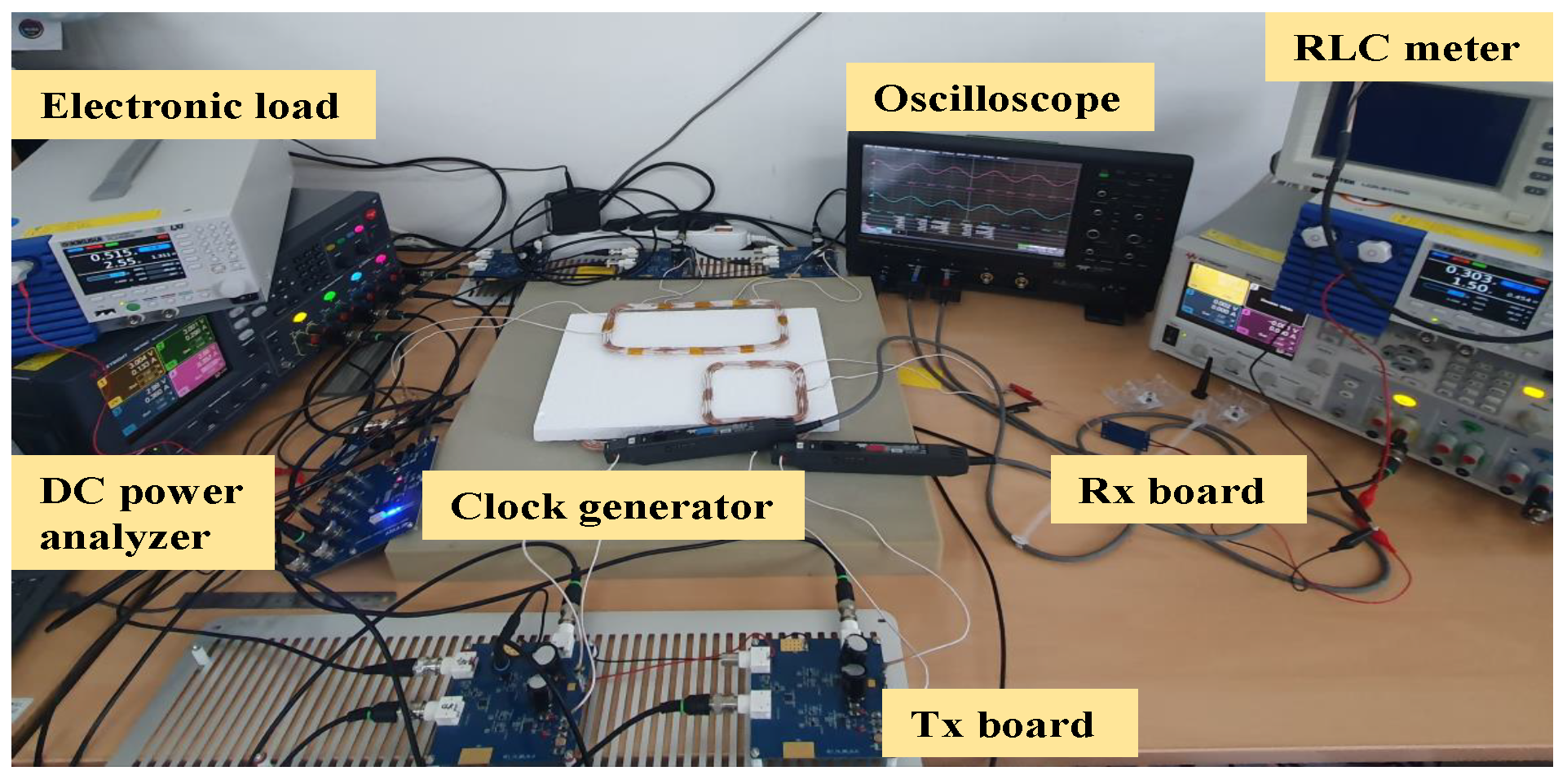
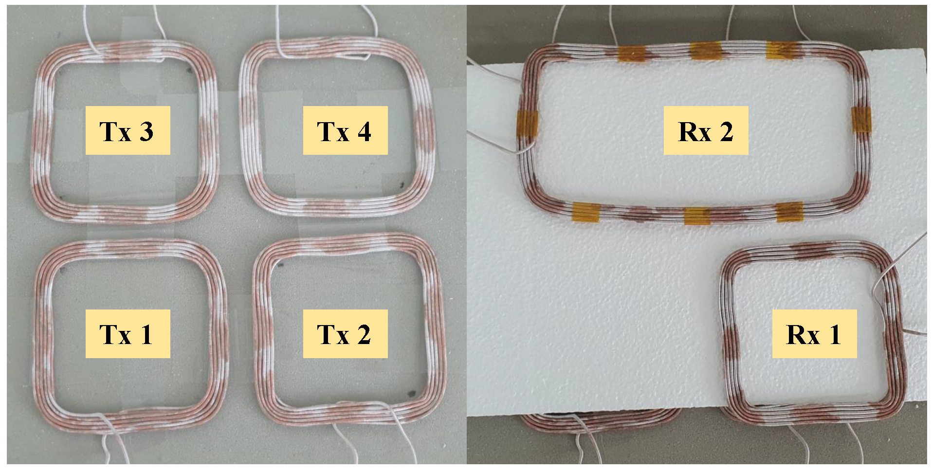
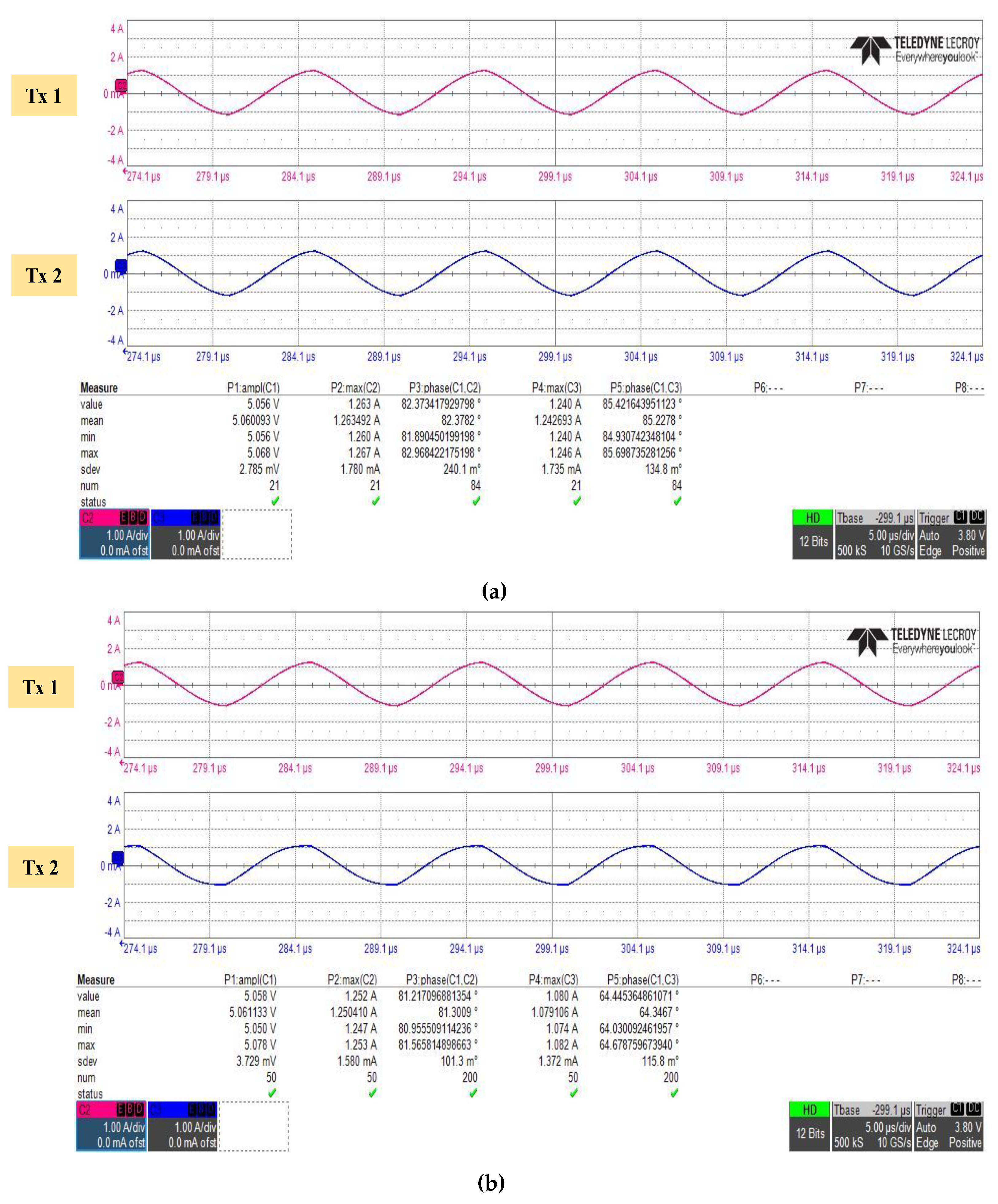
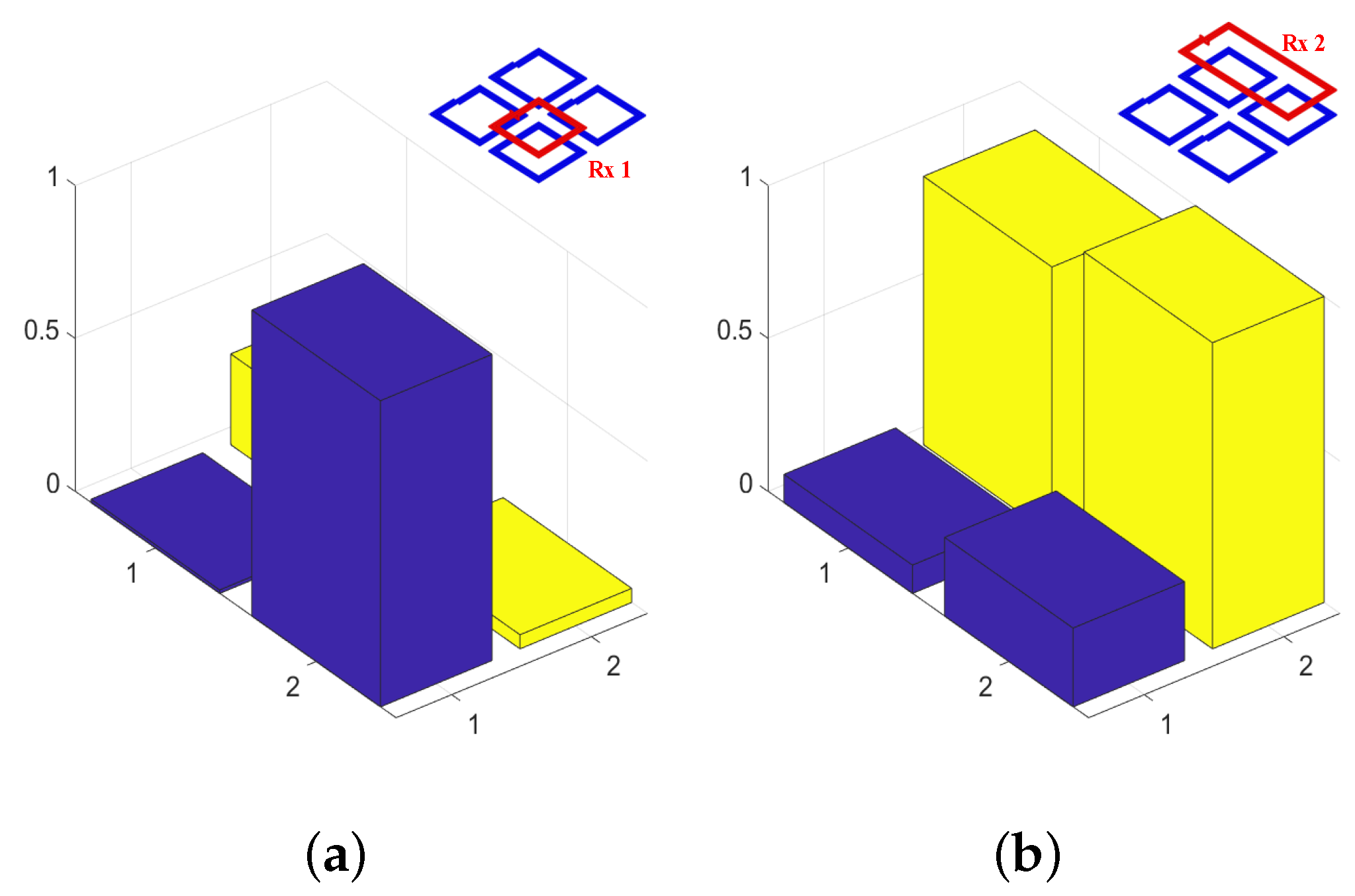
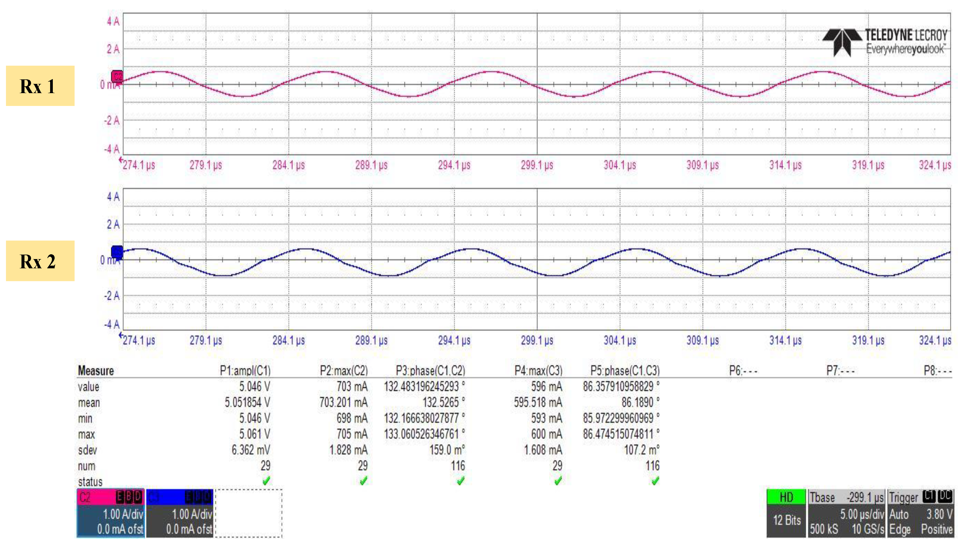
4. Experimental Verifications

Figure 5 shows the experimental setup for validating the proposed method. The Tx coil is controlled by the Tx board, and DC power analyzer and clock generator are connected to the Tx board to control the magnitude and phase of the voltage. The Rx coil is connected to the Rx board, and the AC current is converted into DC current by the board so that it can flow into the electronic load. An oscilloscope is used to measure the current flowing in the coils. Tx coils and Rx coils are connected with matching capacitors with resonant frequencies of 80 kHz and 100 kHz, respectively. The reason why the Tx and the Rx coil has different resonant frequency is to prevent the Tx board from being damaged by the current generated from the Rx coil. 4 × 2 coils are used, and the Rx coil is placed on styrofoam with a thickness of 2 cm. The length of side of the Tx coil is about 10.5 cm, and the spacing between Tx coils is about 12 cm. The configuration of the coils is shown in Figure 6. Rx 1 is placed on Tx 2, and Rx 2 is placed on Tx 3 and Tx 4. The specifications for each coil are represented in Table 1.
After placing the Tx coils, Z T is calculated as in Equation (4). Then, an arbitrary voltage V T is applied to the Tx coils, and the currents of Tx 1 and Tx 2 are measured when there is no Rx coil and when Rx 1 is placed on Tx 2. Figure 7 shows the current of Tx 1 and Tx 2. Although the magnitude and phase of Tx 1 hardly change, it can be seen that there is a change in Tx 2. That is, it can be confirmed whether there is an Rx coil by sensing the currents of the Tx coils. Since Rx 1 is placed in the same position as Tx 2, the currents in Tx 3 and Tx 4 are hardly changed.
Since Rx 1 is entered on primary side, H H R R H ( R x 1 ) must be obtained as shown in Equation (6). Then, Rx 2 is placed on Tx 3 and Tx 4 as shown in Figure 6. The moment Rx 2 enters in, the current of Tx 3 and Tx 4 will change significantly. Therefore, primary side can detect Rx 2 as similar with Rx 1. If Rx 2 is entered, H H R R H ( T o t a l ) can be calculated using Equation (6). Then, H H R R H ( R x 2 ) is calculated using Equation (9), and the eigenvalues and eigenvectors of H H R R H ( R x 1 ) and H H R R H ( R x 2 ) are analyzed. Then, as the proposed method, it is possible to determine which Tx coils are the optimal for each Rx coil. Figure 8 shows the distribution of eigenvectors by analyzing H H R R H ( R x 1 ) and H H R R H ( R x 2 ) . Since Rx 1 is on Tx 2, the second row of eigenvector corresponding to Tx 2 is the largest. In the case of Rx 2, third and fourth rows have large values. In other words, Rx 1 and Rx 2 can uses Tx 2, Tx 3 and Tx 4 to control power, which indicates that Tx 1 is almost useless in this situation.
Each value of i T means the current of the Tx coils. As shown in Figure 8, Tx 1 has little effect on each Rx coil. That is, even if i T 1 is set to 0, it hardly contributes to the entire power efficiency. i T 2 is the current used to transmit power on Rx 1, and when the eigenvector of H H R R H ( R x 1 ) is analyzed, the value in the second row is significantly dominant, and the remaining values are close to 0. Since Tx 2 is used alone to transmit power to Rx 1, power consumption must be largest. i T 3 and i T 4 are used to transmit power to Rx 2, and i T 4 has a slightly stronger influence on Rx 2. Therefore, i T 4 has a higher current than i T 3 . In other words, the power consumed by Tx 1 will be nearly 0, and the power consumed by Tx 2 that transmits power to Rx 1 alone will be the largest. Furthermore, since Tx 4 has a stronger influence on Rx 2, it will consume more power than Tx 3. Based on these analysis, when 1 W of power is transmitted to each Rx coil, the measurement result of the current flowing through the Rx coils is shown in Figure 9. The Tx coil current i T used to transmit 1 W power to the two Rx coils is determined by Equation (11) and scaled by Equation (10). The magnitude of the current flowing through Rx 1 and Rx 2 is 703 mA and 596 mA, respectively. As shown in Table 1, since the internal resistance of Rx 2 is slightly less than that of Rx 1, a lower current flows. The current flowing through the Rx coil is converted into a DC current through the Rx board, and then the DC current flows through the resistor of 5 Ω . Table 2 shows the power consumption at the primary side and at the Rx resistor 5 Ω .
As already analyzed, almost 0 power is consumed in Tx 1, and Tx 2 consumes the largest power with 1.6056 W. Furthermore, Tx 4 consumes more power than Tx 3. Although there is a slight difference between the two Rx coils, it is confirmed that almost 1 W of power is transmitted as aimed. Some errors may occur due to the approximations used in the proposed method and measurement errors during the experiment. The power consumed by the primary side is about 3.64 W, and the power delivered to the secondary side is about 2.11 W, which is confirmed to have an overall power efficiency of about 58%. Power transmission efficiency is maximized when both the Tx and Rx coils have the same resonant frequency. However, in the experiment, in order to prevent damage to the board, the resonant frequency of the primary side and the secondary side were different, so there was a loss in efficiency. As with the measurement results, it is confirmed that the position of the Rx coils can be estimated by the proposed method using only the primary side, and the power transmitted to the Rx coil can be controlled using the result. In the experiment, 4 Tx coils were used due to equipment limitations, but if the system is implemented using a larger number of Tx coils, much more precise power transmission will be possible.

5. Conclusions

A method of estimating the position of the Rx coils without feedback and controlling the transmitted power has been presented. The proposed method is to determine the position of the Rx coils by analyzing the eigenvector of a specific parameter that can be obtained using only primary side. The theoretical part of the method was verified using EM simulator. As a result of the simulation, it was confirmed that the position of the Rx coils can be estimated using the Tx coils without any feedback. The proposed method was verified by constructing a 4 × 2 WPT system, and it was validated that the simulation result and the experimental result are consistent well. Furthermore, it was verified that arbitrary power can be transmitted to the Rx coil using the result of the position of the Rx coil. The experiment was conducted by transmitting about 1 W to Rx 1 and Rx 2, and the efficiency for Rx 1 is about 32.93 % , Rx 2 is 25.03 % , and the overall efficiency is confirmed to be 57.96 % .
The proposed method can be easily extended to more Rx coils. Experiments were conducted with four Tx coils and two Rx coils due to limited equipment. It will be able to estimate the position of Rx coils easily by applying the proposed method for more Rx coils. However, in order to apply to various WPT applications, future study in a larger-scale WPT system with the proposed method is needed for the stability of the power control.

Author Contributions

The present work was conducted in cooperation with all authors. J.H. analyzed the problem and performed numerous simulations and experiments; S.-W.K., I.-K.C. and Y.B.P. contributed to the conceptualization and validation. All authors have read and agreed to the published version of the manuscript.

Funding

This research received no external funding.

Acknowledgments

This work was supported by Electronics and Telecommunications Research Institute (ETRI) grant funded by the Korean government [22ZH1140, Study on 3D Communication Technology for Hyper-Connectivity].

Conflicts of Interest

The authors declare no conflict of interest.

References

  1. Xie, L.; Cao, X.; Xu, J.; Zhang, R. UAV-Enabled Wireless Power Transfer: A Tutorial Overview. IEEE Trans. Green Commun. Netw. 2021, 5, 2042–2064. [Google Scholar] [CrossRef]
  2. Mahesh, A.; Chokkalingam, B.; Mihet-Popa, L. Inductive Wireless Power Transfer Charging for Electric Vehicles–A Review. IEEE Access 2021, 9, 137667–137713. [Google Scholar] [CrossRef]
  3. Campi, T.; Cruciani, S.; Maradei, F.; Feliziani, M. Efficient Wireless Drone Charging Pad for Any Landing Position and Orientation. Energies 2021, 14, 8188. [Google Scholar] [CrossRef]
  4. Kim, J.; Marin, G.; Seo, J.M.; Neviani, A. A 13.56 MHz reconfigurable step-up switched capacitor converter for wireless power transfer system in implantable medical devices. Analog. Integr. Circuits Signal Process. 2022, 110, 517–525. [Google Scholar] [CrossRef]
  5. Tung, L.V.; Seo, C. A Miniaturized Implantable Antenna for Wireless Power Transfer and Communication in Biomedical Applications. J. Electromagn. Eng. Sci. 2022, 22, 440–446. [Google Scholar] [CrossRef]
  6. Park, Y.J. Next-Generation Wireless Charging Systems for Mobile Devices. Energies 2022, 15, 3119. [Google Scholar] [CrossRef]
  7. Linlin, T.; Xueliang, H.; Hui, L.; Hui, H. Study of Wireless Power Transfer System Through Strongly Coupled Resonances. In Proceedings of the 2010 International Conference on Electrical and Control Engineering, Wuhan, China, 25–27 June 2010; pp. 4275–4278. [Google Scholar] [CrossRef]
  8. Yan, Z.; Yang, B.; Liu, H.; Chen, C.; Waqas, M.; Mai, R.; He, Z. Efficiency Improvement of Wireless Power Transfer Based on Multitransmitter System. IEEE Trans. Power Electron. 2020, 35, 9011–9023. [Google Scholar] [CrossRef]
  9. Mou, X.; Groling, O.; Sun, H. Energy-Efficient and Adaptive Design for Wireless Power Transfer in Electric Vehicles. IEEE Trans. Ind. Electron. 2017, 64, 7250–7260. [Google Scholar] [CrossRef] [Green Version]
  10. Oh, H.; Oh, S.; Koo, H.; Choi, W.; Shin, J.; Hwang, K.C.; Lee, K.Y.; Yang, Y. Mid-Range Wireless Power Transfer System for Various Types of Multiple Receivers Using Power Customized Resonator. IEEE Access 2021, 9, 45230–45241. [Google Scholar] [CrossRef]
  11. Rong, C.; He, X.; Liu, M.; Wang, Y.; Liu, X.; Lu, C.; Zeng, Y.; Liu, R. Omnidirectional Free-Degree Wireless Power Transfer System Based on Magnetic Dipole Coils for Multiple Receivers. IEEE Access 2021, 9, 81588–81600. [Google Scholar] [CrossRef]
  12. Huang, Y.; Liu, C.; Xiao, Y.; Liu, S. Separate Power Allocation and Control Method Based on Multiple Power Channels for Wireless Power Transfer. IEEE Trans. Power Electron. 2020, 35, 9046–9056. [Google Scholar] [CrossRef]
  13. Jeong, S.Y.; Kwak, H.G.; Jang, G.C.; Choi, S.Y.; Rim, C.T. Dual-Purpose Nonoverlapping Coil Sets as Metal Object and Vehicle Position Detections for Wireless Stationary EV Chargers. IEEE Trans. Power Electron. 2018, 33, 7387–7397. [Google Scholar] [CrossRef]
  14. Hwang, K.; Cho, J.; Park, J.; Har, D.; Ahn, S. Ferrite Position Identification System Operating With Wireless Power Transfer for Intelligent Train Position Detection. IEEE Trans. Intell. Transp. Syst. 2019, 20, 374–382. [Google Scholar] [CrossRef]
  15. Lee, W.S.; Park, S.; Lee, J.H.; Tentzeris, M.M. Longitudinally Misalignment-Insensitive Dual-Band Wireless Power and Data Transfer Systems for a Position Detection of Fast-Moving Vehicles. IEEE Trans. Antennas Propag. 2019, 67, 5614–5622. [Google Scholar] [CrossRef]
  16. Han, W.; Chau, K.T.; Jiang, C.; Liu, W. Accurate Position Detection in Wireless Power Transfer Using Magnetoresistive Sensors for Implant Applications. IEEE Trans. Magn. 2018, 54, 1–5. [Google Scholar] [CrossRef]
  17. Son, S.; Shin, Y.; Woo, S.; Ahn, S. Sensor Coil System for Misalignment Detection and Information Transfer in Dynamic Wireless Power Transfer of Electric Vehicle. J. Electromagn. Eng. Sci. 2022, 22, 309–318. [Google Scholar] [CrossRef]
  18. Liang, C.; Zhang, Y.; Li, Z.; Yuan, F.; Yang, G.; Song, K. Coil Positioning for Wireless Power Transfer System of Automatic Guided Vehicle Based on Magnetic Sensing. Sensors 2020, 20, 5304. [Google Scholar] [CrossRef]
  19. Hwang, K.; Cho, J.; Kim, D.; Park, J.; Kwon, J.H.; Kwak, S.I.; Park, H.H.; Ahn, S. An Autonomous Coil Alignment System for the Dynamic Wireless Charging of Electric Vehicles to Minimize Lateral Misalignment. Energies 2017, 10, 315. [Google Scholar] [CrossRef]
  20. Al Sinayyid, J.; Takhedmit, H.; Poulichet, P.; Grzeskowiak, M.; Diet, A.; Lissorgues, G. A Reconfigurable Coil Grid for Receiver Localization in Wireless Power Transfer and Magnetic Field Steering. IEEE J. Radio Freq. Identif. 2021, 5, 128–138. [Google Scholar] [CrossRef]
  21. Hou, X.; Kang, L.; Hu, S.; Yang, H. Mutual Inductance Estimation of Multiple Input Wireless Power Transfer for Charging Electronic Equipment. J. Phys. Conf. Ser. 2020, 1617, 012027. [Google Scholar] [CrossRef]
  22. Simonazzi, M.; Sandrolini, L.; Mariscotti, A. Receiver Coil Location Detection in a Dynamic Wireless Power Transfer System for Electric Vehicle Charging. Sensors 2022, 22, 2317. [Google Scholar] [CrossRef] [PubMed]
  23. Cao, G.; Zhou, H.; Zhang, H.; Xu, J.; Yang, P.; Li, X.Y. Requirement-Driven Magnetic Beamforming for MIMO Wireless Power Transfer Optimization. In Proceedings of the 2018 15th Annual IEEE International Conference on Sensing, Communication, and Networking (SECON), Hong Kong, China, 11–13 June 2018; pp. 1–9. [Google Scholar] [CrossRef]
  24. Shi, L.; Kabelac, Z.; Katabi, D.; Perreault, D. Wireless Power Hotspot That Charges All of Your Devices. In Proceedings of the 21st Annual International Conference on Mobile Computing and Networking. Association for Computing Machinery, Paris, France, 7–11 September 2015; MobiCom ’15. pp. 2–13. [Google Scholar] [CrossRef] [Green Version]
  25. Kurs, A.; Karalis, A.; Moffatt, R.; Joannopoulos, J.D.; Fisher, P.; Soljačić, M. Wireless Power Transfer via Strongly Coupled Magnetic Resonances. Science 2007, 317, 83–86. [Google Scholar] [CrossRef] [PubMed] [Green Version]
  26. Huh, S.; Ahn, D. Two-Transmitter Wireless Power Transfer with Optimal Activation and Current Selection of Transmitters. IEEE Trans. Power Electron. 2018, 33, 4957–4967. [Google Scholar] [CrossRef]
  27. Jadidian, J.; Katabi, D. Magnetic MIMO: How to charge your phone in your pocket. In Proceedings of the Annual International Conference on Mobile Computing and Networking, MOBICOM, Maui, HI, USA, 7–11 September 2014. [Google Scholar] [CrossRef]
Figure 1. The configuration of n × k magnetic resonant WPT system.
Energies 15 08621 g001
Figure 2. Simulation model for estimating Rx coils position.
Energies 15 08621 g002
Figure 3. Comparison result of eigenvector and mutual inductance distribution when there is only one Rx coil. (a) Mutual inductance distribution. (b) Normalized eigenvector distribution.
Energies 15 08621 g003
Figure 4. Comparison result of eigenvector and mutual inductance distribution for case 6. (a) Mutual inductance distribution with two Rx coils. (b) Normalized eigenvector distribution of H H R R H ( R x 1 ) (left), and H H R R H ( R x 2 ) (right).
Energies 15 08621 g004
Figure 5. Experimental setup.
Energies 15 08621 g005
Figure 6. Configuration of Tx coils and Rx coils.
Energies 15 08621 g006
Figure 7. Measurement of the current of Tx 1 and Tx 2. (a) When there is no Rx coil. (b) When Rx 1 is placed on Tx 2.
Energies 15 08621 g007
Figure 8. Eigenvector distribution. (a) H H R R H ( R x 1 ) . (b) H H R R H ( R x 2 ) .
Energies 15 08621 g008
Figure 9. Measurement results for Rx coil current when 1 W of power is received.
Energies 15 08621 g009
Table 1. Specifications for all coils.
Tx 1Tx 2Tx 3Tx 4Rx 1Rx 2
R (m Ω )339.6897.3962.865.18168.07140.8
L ( μ H)19.6620.0619.620.6419.7534.81
C (nF)201.36197.17201.9191.7200.3572.77
Table 2. Consumed power at the primary side and Rx resistor.
Tx 1Tx 2Tx 3Tx 4Rx 1Rx 2
P (W)01.60560.88201.15631.20.912
Publisher’s Note: MDPI stays neutral with regard to jurisdictional claims in published maps and institutional affiliations.

