Article

Chlorine Corrosion in a Low-Power Boiler Fired with Agricultural Biomass

by
Danuta Król
1,
Przemysław Motyl
2,* and
Sławomir Poskrobko
3
1
Faculty of Energy and Environmental Engineering, Silesian University of Technology, 14-100 Gliwice, Poland
2
Faculty of Mechanical Engineering, University of Technology and Humanities in Radom, 26-600 Radom, Poland
3
Faculty of Civil Engineering and Environmental Sciences, Białystok University of Technology, 15-351 Białystok, Poland
*
Author to whom correspondence should be addressed.
Energies 2022, 15(1), 382; https://doi.org/10.3390/en15010382
Submission received: 2 December 2021 / Revised: 28 December 2021 / Accepted: 30 December 2021 / Published: 5 January 2022

Abstract

:
The selection of appropriate heat-resistant materials which are at the same time resistant to atmospheres rich in chlorine and its compounds is one of the most important current construction problems in steel boiler elements when using biomass fuels of agricultural origin. In the research presented here, an area was identified in the furnace of a 10 kW boiler where there was a potential risk of chlorine corrosion. This zone was determined based on numerical analysis of the combustion process; it is the zone with the highest temperatures and where the gas atmosphere conducive to the formation of chlorine corrosion centers. Subsequently, tests were carried out in the process environment of the combustion chamber of a 10 kW boiler (the fuel was barley straw) by placing samples of eight construction materials in a numerically-designated zone. These included samples of steel (coal boiler St41K, heat-resistant H25T and H24JS, and heat-resistant valve 50H21G9N4) as well as intermetallic materials based on phases (FeAl, Fe3Al, NiAl, and Ni3Al). The samples remained in the atmosphere of the boiler furnace for 1152 h at a temperature of 750–900 °C. After this time, the surfaces of the samples were subjected to SEM microscopy and scanning analysis. The results showed that the St41K boiler steel was not suitable for operation under the assumed conditions, and that a thick layer of complex corrosion products was visible on its surface. The least amount of corrosion damage was observed for the samples of 50H21G9N4 steel and intermetallic materials.

1. Introduction

One of the most important directions for the development of renewable energy is the rational diversification of the use of various energy-generation technologies. The most recently developed technologies, although not always finding economic justification, are wind and solar energy and heat pumps. In developed countries, there is more and more talk about energy based on hydrogen fuel (i.e., blue, gray and green hydrogen), and the discussion of the technologies for producing these fuels is only beginning. For this reason, it is too early to look for rational justifications for the use of hydrogen fuel in municipal or industrial energy. It is all the more difficult when it comes to prosumer (or home) energy. Therefore, the need to use traditional technologies based on solid biomass fuels remains.
The most well-known and commonly used fuel in professional, communal and domestic energy is wood biomass [1,2,3,4]. Wood biomass combustion technologies have been developing for many years, achieving high performance parameters defined by efficiency and environmental parameters characterized by low emissions of gaseous combustion products, mainly NOx [5,6] and fly dust [7,8]. The subject-rich literature, e.g., [9,10,11,12], indicates that achieving high combustion efficiency (over 0.9) and low emissions (especially in the range of NOx, below 200 mg/Nm3, and dust) is a challenge for new high-efficiency and low-emission technologies relying on the combustion of fuels from wood biomass.
The development of biomass technologies, particularly important for small domestic boilers, is heading towards limiting the use of biomass of wood origin. The limitations result from the decreasing supply of wood biomass, which leads to the increase in the price of this fuel. Harvesting of wood can be devastating to the environment, and it often cannot grow at the same pace as has been the case thus far. Power plants and combination heat and power plants most often use wood biomass, that is, wood chips and pellets from sawdust and to a lesser extent residues and waste from agriculture or the agri-food industry. Considerable amounts of firewood are burned (apart from commercial and communal power plants) in households in low-power 10–20 kW boilers. Therefore, it is necessary to successively replace wood biomass with biomass of agricultural origin, i.e., from agricultural production or the food industry, as well as from energy crops. This represents a way to diversify energy sources and suppliers, and thus to use local energy resources and not only fossil fuels (i.e., coal, liquid fuels and natural gas) and nuclear fuels, which should directly contribute to the creation of new jobs.
Regular harvesting of large amounts of non-forest biomass creates a number of various difficulties. In addition, biomass, e.g., agricultural product, with a relatively high (compared to wood biomass) share of nitrogen, chlorine, sulfur and alkaline elements (Ca, K, Na) has a negative impact on the operation of energy boilers due to the potential risk of slagging heating surfaces, and of chlorine and chloride corrosion. The combustion of such types of biomass [9,10] in power boilers installed in heating plants and combined heat and power plants is, among others, a source of significant emissions of nitrogen oxides, sulfur and hydrogen chloride. Moreover, alkali metal chlorides lower the ash melting point, which results in technical and technological problems, namely the risk of slagging and corrosion [11]. In biomass, chlorine occurs in inorganic compounds, the most common of which are NaCl and KCl [12]. Many years of experience in the operation of boilers intended for professional and municipal power plants, in which such fuels are burned, indicates accelerated wear of steel structural elements such as screens, evaporators, steam superheaters, etc., caused by the corrosive action of chlorine and hydrogen chloride [13,14]. Corrosion damage is mainly caused by molecular chlorine, which is a product of oxidation of hydrogen chloride contained in exhaust gases, as well as by alkali metal chlorides. This local corrosion damage is called chemical corrosion or chlorine high-temperature corrosion [15,16]. Chlorine and hydrogen chloride, however, not only cause corrosive processes; they are precursors of the formation of chlorinated dibenzodioxins and PCDD/F furans [17], i.e., compounds of the highest toxicity that pose a threat to living organisms. The results of research on the reduction of HCl during the combustion of biomass materials or waste and methods of reducing corrosion processes by the use of fuel additives (the effect of which is to reduce HCl directly in the furnace [18,19]), as well as the processes affecting high-temperature chlorine corrosion, are extensively presented in many publications, e.g., [20,21,22,23]. All of the works presented in the literature concern boilers intended for the commercial power industry (i.e., power plants, combined heat and power plants, heating plants).
Many publications discuss the results of tests in which heat-resistant steels with increased resistance were exposed to high-temperature chlorine corrosion, e.g., [20,21,22,23]. The susceptibility of SA-213T-22 low-chromium steels to chlorine corrosion of steam superheaters in a 100 MW boiler was investigated in [24]. The fuel for the boiler was hard coal with a high chlorine content (for various coals, this was from 908 to 1684 ppm). Observations were made over the course of 500 h. The authors did not specify the connections in which the chlorine was present, which is important for the identification of the corrosion process. The tests were carried out at a temperature of 500 °C. Presented in [25], another study showed the resistance to chlorine corrosion of protective layers applied to steel surfaces with the HVOV and HVAV methods. The method of spraying Cr3C2-18NiCoCr via HVOF technology turned out to be the most effective. In the results of the research cited above, the steel construction elements of the furnace were most effectively protected against the corrosive effects of chlorine by spraying protective layers on these elements. In [26], it was shown that spraying an NiCr protective layer via the high-temperature method (e.g., laser method) contributes to much better protection than low-temperature spraying below 100 °C. The authors found that the high-porosity protective layer placed at low temperature was more exposed to the penetration of chlorine into the material (penetration approx. 600 μm) than the layer placed at high temperature, which was characterized by low porosity (penetration approx. 80 μm). The exposure time of the sample was 360 h. NiMoCrW and CoNi CrAl coatings applied to steel surfaces using HVOF technology showed higher resistance to the corrosive effects of chlorine at a temperature of about 650 °C [27]. The tests were performed in the presence of sediment, (which was a mixture of NaCl and KCl alkali salts typical of biomass) for 350 h. The results indicated that an effective way to protect steel structural elements of boiler furnaces against the high-temperature corrosive effects of chlorine is to coat these elements with a protective coating of Al, Ni, Mo, and Cr metals. These coatings, under high-temperature conditions, are characterized by low porosity, which significantly hinders the emergence of high-temperature chlorine corrosion of the steel structural elements of boiler furnaces and steam superheaters. The discussed methods relate to the protection of construction materials of boilers intended for the commercial power industry. The problem is still unresolved when chlorine corrosion concerns low-power boilers for heating buildings, most often located in rural areas, which burn biomass fuels of agricultural origin often rich in chlorine. The issue of chlorine corrosion of construction materials in low-power boilers is not of interest to researchers, and the manufacturers of such boilers do not take any steps to protect the construction material against the effects of chlorine corrosion. Due to the increasing use of renewable fuels in so-called domestic boilers (for which the fuel is and will be biomass, and to an increasing extent biomass of agricultural origin), taking up this research challenge and drawing attention to the existence of the problem of corrosivity is now a necessity. Therefore, the aim of the research, the results of which are presented in this paper, was to identify the places in the furnace of a domestic boiler that are most exposed to the corrosive effects of chlorine. This research work has been carried out in the following manner:
-
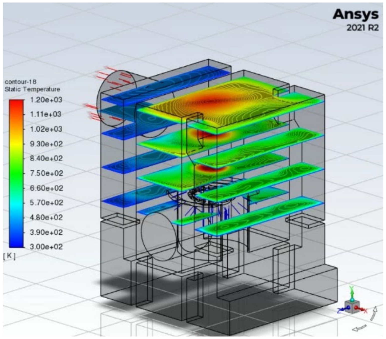
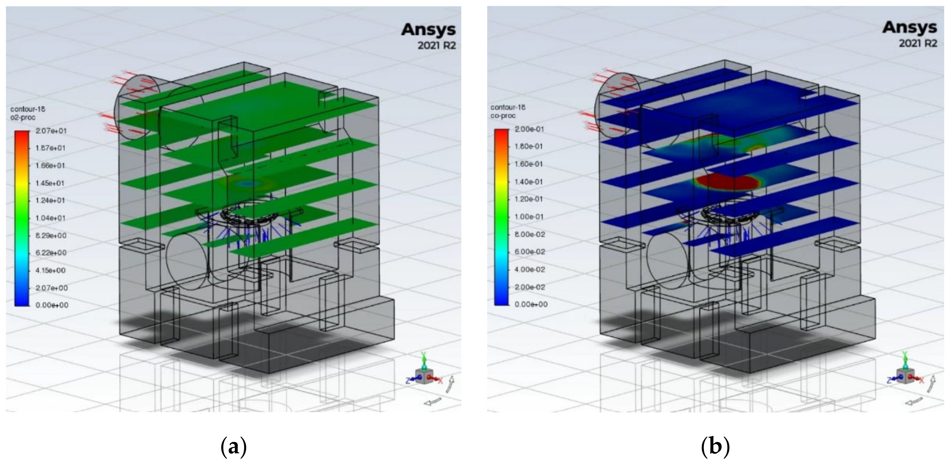
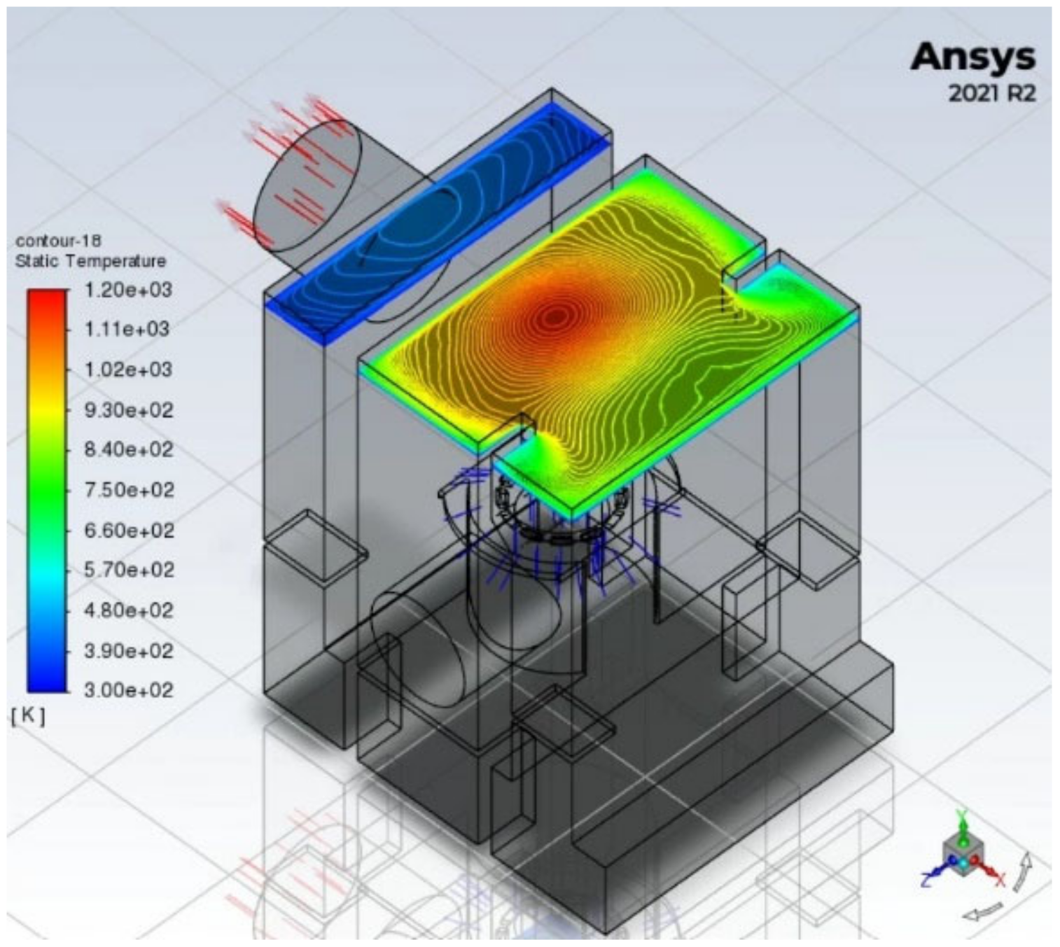
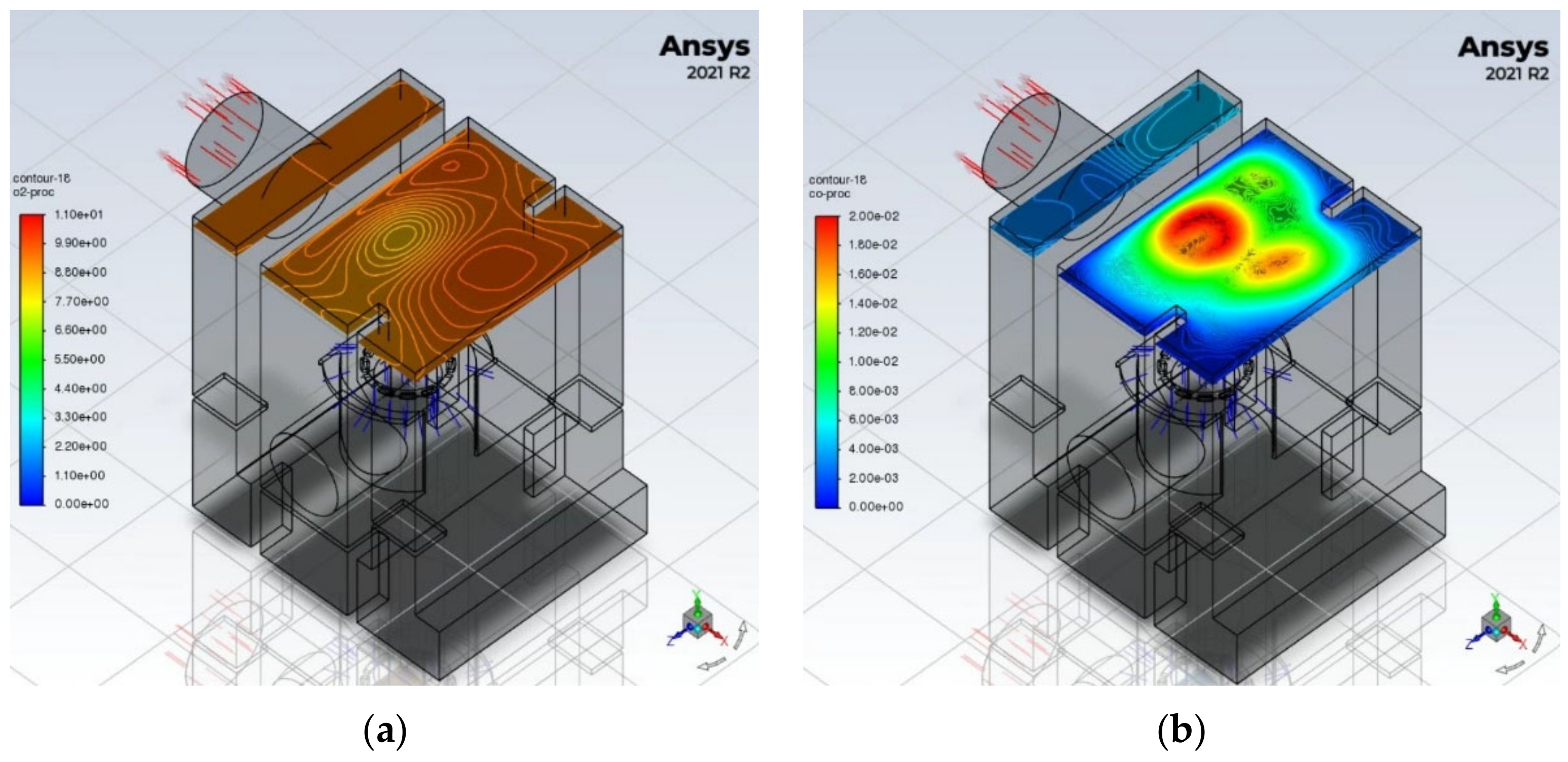
Identification of possible potential areas of the boiler furnace exposed to corrosive chlorine by means of numerical thermal and flow analysis in the design phase;
-
Testing of steel construction materials with heat-resistant properties in the area of the furnace of the boiler selected as above as the most exposed to corrosive chlorine;
-
Presentation of the possibility of using new heat-resistant materials, FeAl, and FeNi intermetals, as structural elements in a numerically-determined area exposed to the corrosive effects of chlorine.

2. Chemical Process

2.1. Transformation of Chlorine Compounds in the Process of Biomass Combustion

Formation of hydrogen chloride HCl (chloride sulfatization) [28]:
2NaCl + SO2 + H2O + ½O2 → Na2SO4 + 2HCl
2NaCl + SO2 +H2O → Na2SO3 + 2HCl
2KCl + SO2 + H2O +½O2 → K2SO4 + 2HCl
2KCl + SO2 + H2O → K2SO3 + 2HCl
The intensity of HCl formation increases with increasing temperature, and the highest efficiency is achieved at 700–900 °C. Then, the alkali metal chlorides are in gaseous form.
Formation of molecular chlorine Cl2 [28]:
2NaCl + SO2 + O2 → Na2SO4 + Cl2
2NaCl + ½O2 → Na2O + Cl2
2KCl + SO2 + O2 → K2SO4 + Cl2
2KCl + ½O2 → K2O + Cl2
Secondary processes of hydrogen chloride formation:
Cl2 + H2O = 2HCl + ½O2
Cl2 + SO2 + H2O → 2HCl + SO3

2.2. Mechanism of Chloride Corrosion

In a strongly oxidizing environment, there is a possibility of a Deacon reaction, the oxidation of HCl to molecular chlorine Cl2 [28]:
4HCl + O2 → 2Cl2 + 2H2O
This reaction takes place at a temperature that does not exceed 400–600 °C, in the environment of mineral deposits formed from fly dusts lying on the walls of boiler furnaces and exchanger elements, or on the surface of the fly dust, provided that the temperature conditions are appropriate. At high exhaust gas temperatures, the equilibrium of this reaction is on the left side (a large amount of HCl and small amount of Cl2), while at a much lower temperature near the surface of the pipes the equilibrium shifts to the right.
The source of Cl2 at the metal surface may be reactions in which chlorides of potassium (K) and sodium (Na) condensing on the pipes react with iron oxides [28]:
2NaCl + Fe2O3 + ½O2 → Na2Fe2O4 + Cl2
2KCl + Fe2O3 + ½O2 → K2Fe2O4 + Cl2
If sulfur dioxide (SO2) is present in the flue gas, alkali metal chlorides in the sludge may undergo sulfurization:
1. solid phase reactions with release of Cl2; these are reactions (5) and (7).
The chlorine diffuses through the precipitate into the metal of the pipe and reacts with it to form iron chloride [28]:
Fe + Cl2 →FeCl2
Iron (II) chloride formed on the surface of the metal has a high vapor pressure at a temperature of 500 °C, which causes it to pass into the gas phase, and by diffusing through the protective oxide layer, it damages it. If it is an area rich in oxygen, molecular chlorine and iron oxides are formed again [28]:
2FeCl2(g) + 3/2O2→ Fe2O3(s) + 2Cl2
3FeCl2(g) + 2O2→ Fe3O4(s) + 3Cl2
Due to the porosity, the oxide layer recreated at the surface of the pipe no longer has any protective properties. The Cl2 released in this reaction diffuses back through the oxide layer into the pipe and reacts with the metal.
2. Reactions in the gas phase with the release of HCl; these are reactions (1) and (3).
Under the reducing conditions prevailing periodically in the combustion chamber, alkali metal chlorides are stable in form and do not undergo sulphation. At lower temperature ranges, the above reactions also have very slow kinetics.

2.3. Heavy Metals in Fuel and High-Temperature Chlorine Corrosion

The presence of chlorine, which causes the conversion of heavy metals to the form of their chloride vapors, has a significant impact on the corrosion of steel in power devices (e.g., grates, screens, exchanger elements) initiated by the presence of hydrogen chloride, alkali metals, and to a lesser extent heavy metals. Chloride corrosion intensifies when the sediments deposited on the pipes containing potassium and sodium chlorides are present in the liquid phase. The melting points of KCl and NaCl are 772 and 801 °C, respectively; however, their heavy metal chloride eutectics have much lower melting points (Table 1). For this reason, in boilers burning biomass containing chlorine, alkali and heavy metals, the risk of corrosion occurs at a temperature of 250 °C [28].
In summation, the process of chlorine high-temperature corrosion is influenced by such factors as exhaust gas temperature, oxygen concentration in the exhaust gas (which determines oxidizing or reducing conditions), concentration of hydrogen chloride, chlorine and SO2 in exhaust gases, concentration of alkali metals and heavy metals in the gas phase and fly ash, and the melting point of ash sediments.

3. Experimental Research
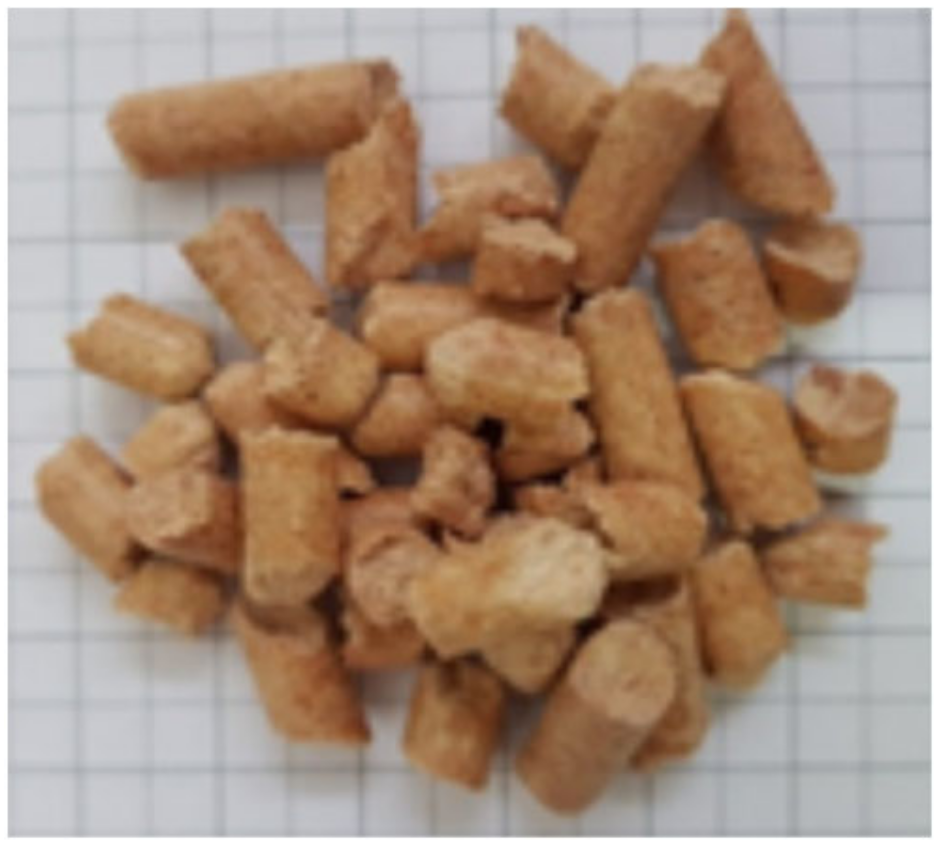
The research experiment included testing the strength, that is, the resistance to chlorine corrosion, of construction materials used or likely to be used in the construction of low-power boilers. The research was carried out in the work environment of the combustion chamber of a 10 kW boiler, and the fuel was agricultural biomass. In order to accomplish this task, it was first necessary to identify the possibility of potential chlorine corrosion outbreaks; thus, a numerical code was used. Data for numerical calculations were obtained by burning agricultural biomass in a low-power 10 kW boiler, as described above, on the test stand described in detail in [29], measuring the composition of CO, CO2, CH4, H2 and O2 gases at the exit of the burner.

3.1. Fuel

Biomass fuel in the form of pellets made of barley straw was used for the research (Figure 1).
The fuel properties and the content of alkali metals in the combusted biomass are presented in the tables below, Table 2 and Table 3. The fuel moisture was checked regularly and stored in the laboratory at an almost constant ambient temperature of 18–19 °C.

3.2. Numerical Method

In order to identify areas with an increased risk of corrosion, a numerical model of the boiler was used; this boiler was developed and its correct operation verified as presented in [29]. Numerical simulation was performed using a semi-empirical method in which an experiment was carried out to determine the composition of the synthesis gas, which is the product of gasification processes taking place in the burner. The numerical methods presented in [29] with a numerical grid consisting of 1 million polyhedral cells were used to model flows, heat transfer and chemical reactions. Due to the nature of the exhaust gas flow with its observed tendency for turbulence, numerical modeling of the flow and heat transfer was a useful method for identifying zones where control samples could be placed. The numerical model made it possible to analyze the temperature and the concentrations of oxygen and carbon monoxide anywhere in the combustion chamber (Figure 6a). To facilitate the presentation of the results, four control planes were adopted at heights of 0.28, 0.38, 0.48 and 0.58 m (Figure 6b).
Figure 2, Figure 3, Figure 4 and Figure 5 show the temperature distribution and the O2 and CO concentration. The structure of the combustion chamber (Figure 6), as well as the type of burner used, favor the lifting of the hot gas stream towards the upper wall of the boiler. In Figure 2, a temperature zone of 1000–1200 K can be observed in the central part of the top wall, along with a gradual decrease in temperature towards the side walls of the combustion chamber. The resulting swirl of gases in the combustion chamber promotes an even distribution of oxygen, the average values of which are in the range of 10–11% (Figure 3a and Figure 5a). The combustion process with excess air (λ = 2), as well as the aforementioned swirling and mixing of the exhaust gases in the combustion chamber, favor a low CO content (<0.02%) both in the upper part of the combustion chamber (Figure 3b and Figure 5b) and at the shaft through which the exhaust gases are directed to the convection line (Figure 6b).
The numerical model made it possible to analyze the temperature and the concentrations of oxygen and carbon monoxide anywhere in the combustion chamber (Figure 6a). To facilitate the presentation of the results, four control planes were adopted at heights of 0.28, 0.38, 0.48 and 0.58 m (Figure 6b).

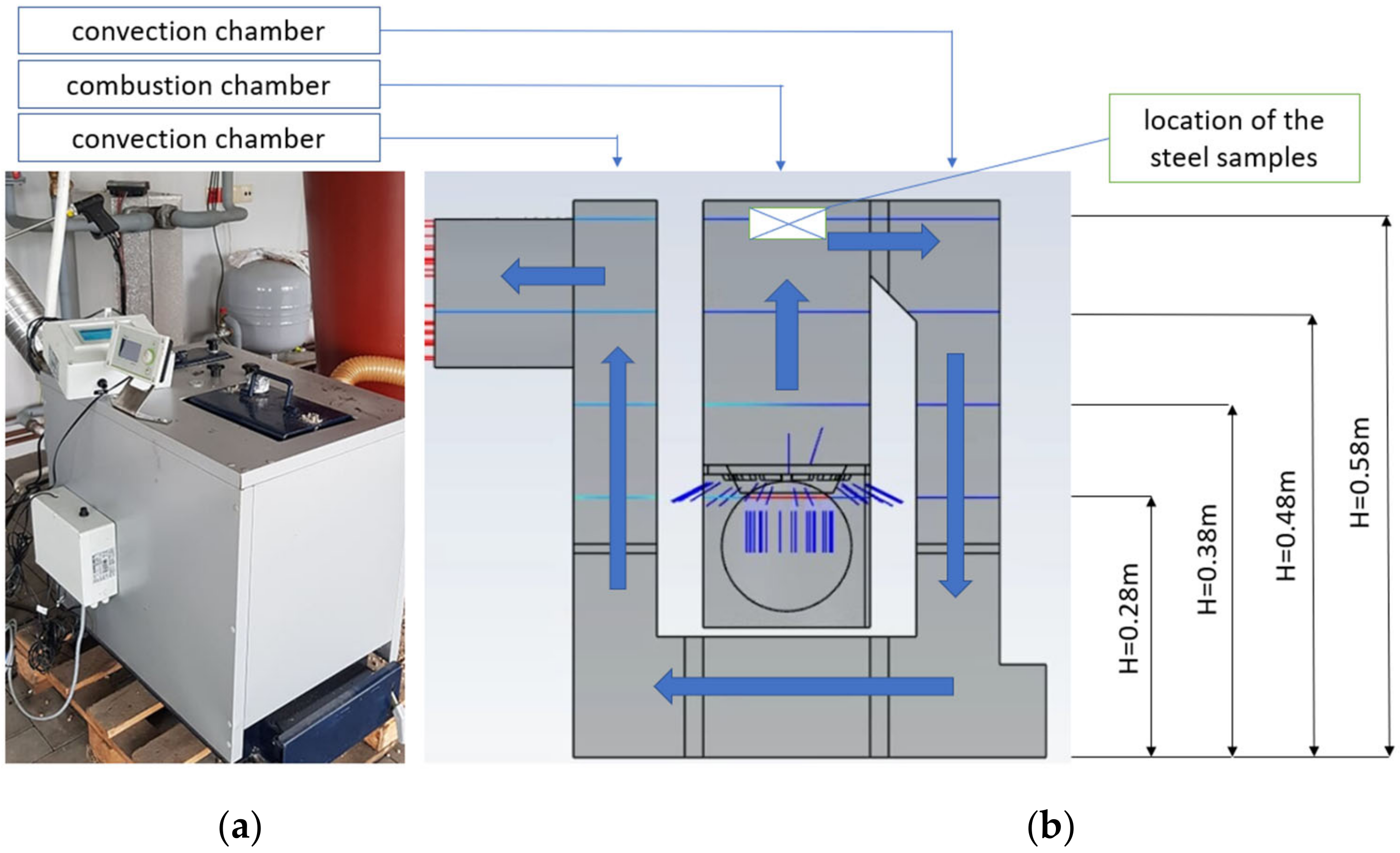
3.3. Test Stand Experiment

In the zone of the highest temperature of the boiler furnace determined in the numerical analysis (red areas in Figure 2 and Figure 4), where chlorine corrosion may appear and lead to the destruction of the boiler construction material (Figure 6), samples of various grades of steel (carbon steel, heat-resistant, creep-resistant and intermetallic samples) as well as alloys based on aluminum intermetallic phases of the FeAl and NiAl system were placed. Then, for 48 days (1152 h), fuel (barley straw pellets, as described in point Section 3.1.) were dosed to the boiler during the combustion process. The average temperature in the combustion chamber had a range of 750–900 °C (1023–1173 K). After this time, samples of steels and intermetallic materials were taken out and their surface conditions were analyzed. The annealing time of the samples is justified by the fact that the observations of corrosion damage under the conditions of the described experiment were previously carried out for a period of one week to three months, and on this basis it was established that within 48 days there were significant changes on the surface of the samples.

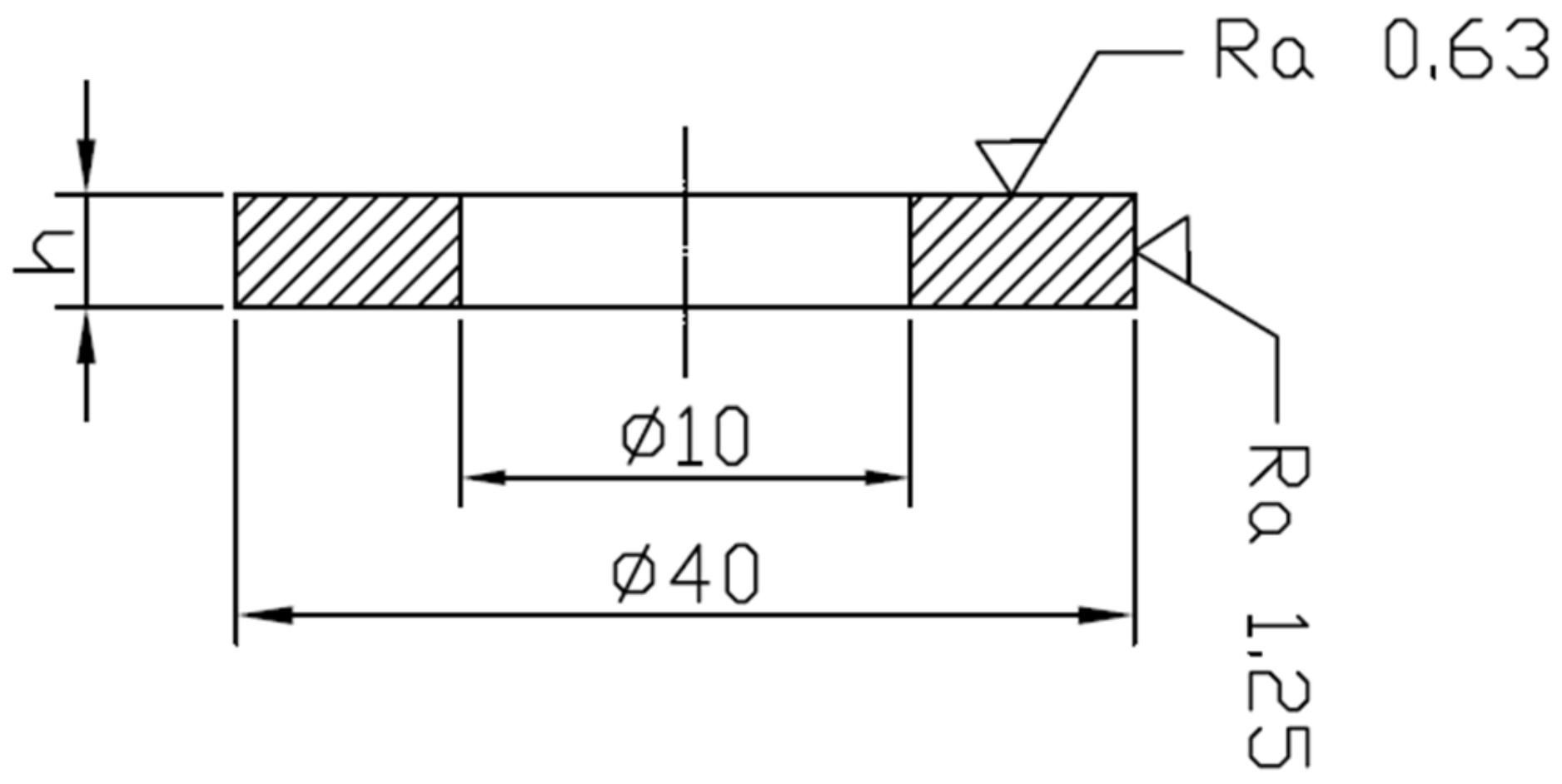
Tested Construction Materials

The following steels were selected for the research:
  • Carbon boiler steel St41K (acc. EN—P 1265 GH); components (wt%)—Fe 98.868; Cr 0.02; P 0.01; Si 0.02; Mn 0.87; Ni 0.01; Mo 0.001; Al 0.043; S 0.008; C 0.15
  • Heat-resistant steel H25T (acc EN—1.4749; acc DIN X18CrN28); components (wt%)—Fe 74.107; Cr 24.35; P 0.40; Si 0.40; Mn 0.48; Ni 0.037; Mo 0.06; Ti 0.025; S 0.003; C 0.06
  • Heat-resistant steel H24JS (acc EN—1.4762; acc DIN—X10CrAl24); components (wt%)—Fe 70.753; Cr 24.96; P 0.045; Si 1.45; Mn 0.70; Ni 0.32; Mo 0.09; Cu 0.15; Al 1.45; S 0.002; C 0.08
  • Heat-resistant valve steel 50H21G9N4 (acc EN—1.4871; acc DIN—X53CrMnNiN21-9); components (wt%)—Fe 64.378; Cr 21.52; P 0.03; Si 0.13; Mn 8.93; Ni 4.5; S 0.002; C 0.51
From the above-mentioned steels, samples were prepared for testing with the dimensions given in Table 4 and shown in Figure 7.
The following intermetals were also selected for the research:
  • FeAl phase based intermetallic material; components (wt%)—Fe 70.25; Al 29.75,
  • Fe3Al phase based intermetallic material; components (wt%)—Fe 91.03; Al 8.97,
  • NiAl phase based intermetallic material; components (wt%)—Ni 72.73; Al 27.27,
  • Ni3Al phase based intermetallic material; components (wt%)—Ni 86.28; Al 13.72.
Intermetallic alloys were prepared, from which the test plates were made. The alloys were made by melting the base materials (Fe3Al, FeAl, Ni3Al, NiAl) in an IS5/III vacuum induction furnace by Leybold-Heraeus, followed by a single remelting, guaranteeing adequate purity and homogeneity of the material. The obtained ingots were then cut and the graphite molds poured into a Balzers VSG-02 oven to obtain plaques 100 mm × 100 mm × 7 mm, which were cut into 35 mm × 35 mm plaques.

4. Results and Discussion

The analysis included the macroscopic evaluation of the corrosion products on the surface of the samples exposed to the combustion chamber atmosphere of the 10 kW boiler fired with biomass (barley straw) followed by examination of the surface of the samples using a HITACHI S-3000N scanning electron microscope with a Noran Vantage chemical composition analyzer.

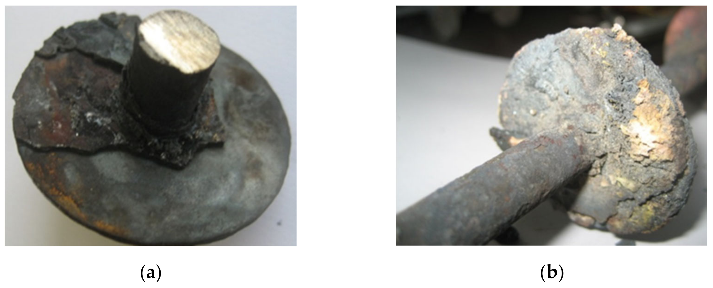
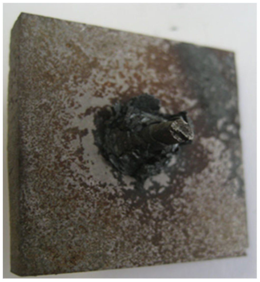
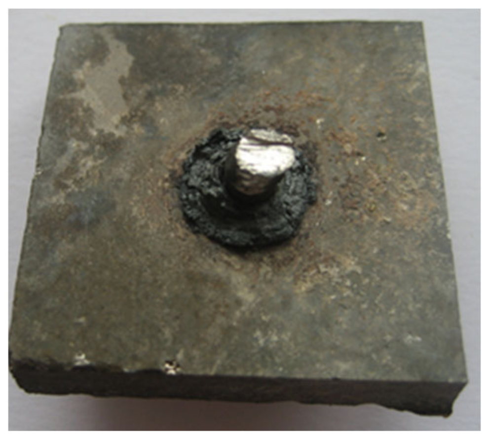
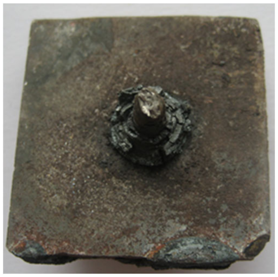
4.1. Visual Assessment

The visual assessment of the surface condition of the samples after taking them out of the boiler showed different levels of destruction of the construction materials. The test results of steel samples indicate that the St41K boiler steel is not suitable for operation under the assumed conditions. On the surface of the boiler steel sample, after 1152 h exposure at temperatures of 750–900 °C, a thick layer of complex corrosion products was visible (Figure 8).
On the other hand, in the case of the alloyed steels, the thickness of the corrosion products on the surface of the alloyed steels was small. In addition to a dense gray bloom on the surfaces, slight delamination of flakes was visible (Figure 9, Figure 10 and Figure 11). Thicker greenish layers appeared only on samples of H25T heat-resistant steel. These results are confirmed in the works of other authors. For example, in [30] the corrosion properties of high-temperature boiler steels (T91, 12Cr1MoVG and TP347H) during coal and biomass combustion were investigated. These fuels had a variable high or low chlorine content. Experiments were carried out over 168 h with SEH ash, Da Nahu ash (DNH), straw ash, wood chip ash and their mixtures in a tube furnace, with a corrosion probe taking into account the temperature gradient–flue gas temperature to the temperature of the pipe wall. SEH ash and straw ash (from fuels with high chlorine content) caused degradation of the material due to its higher Cl and alkali content. On the other hand, the corrosivity of DNH ash and ash from wood shavings (i.e., from fuels with high chlorine content) was low. In addition, TP347H austenitic steel had a higher corrosion resistance than other grades due to its higher chromium and nickel content.
The authors of [31] conducted tests in laboratory conditions at a temperature of 550 °C using the superheater of a boiler fired with biomass fuel. For testing they used samples of low-alloy ferritic and austenitic boiler steels, stainless steels and HVOF coatings. The corrosive environment was caused by the use of a mixture of K2SO4, Na2SO4, KCl, and NaCl salts to simulate boiler deposits. The exposure time of the samples was 100 h. Under oxidizing conditions, the corrosion process was intense on the steel surface. Where an oxide layer was formed on the surface of the samples, it constituted a coating protecting the surfaces of the steel samples against Cl diffusion, i.e., against its corrosive action. The results of similar studies are presented in [32], where the achievement of high durability with chrome coatings was described and justified. In [33], the corrosive behavior of chloride salts was investigated using sodium chloride (NaCl) as a substitute compound by applying a salt layer (4.0 mg/cm2) to the surface of a sample of construction material. Tests were carried out for six different Ni-Cr coatings, including Inconel 625 (Ni-Cr-Mo), SW1600, and SW1641 (Ni-Cr-Mo-B-Si), as well as Colmonoy 88 and SP 99 (Ni-Cr-BW). It was found that the corrosion under the chloride layer was much stronger than in the atmosphere containing HCl. Commercial steel weight loss increased by more than an order of magnitude. Based on the characteristics of the corrosion products, it was found that this behavior was due to a second active oxidation mechanism in which sodium chloride reacts and depletes protective oxides such as chromium (II) oxide. The main corrosion attack observed was pitting under the original salt layer. Colmonoy 88 showed excellent corrosion resistance, with weight loss in the range of 0.3–3.1 mg/cm2 at 450–550 °C, compared to the Ni-Cr-Mo and Ni-Cr-B-So coatings, which showed losses in the range of 10–30 mg/cm2. The enhanced corrosion resistance of Colmonoy 88 and SP 99 was attributed to the addition of a tungsten alloy.
Figure 12, Figure 13, Figure 14 and Figure 15 display pictures of the intermetallic material samples after 1152 h of exposure at temperatures of 750–900 °C in the combustion chamber of the boiler. As can be seen, these materials have good corrosion resistance. The colors of the layers formed on the surfaces of the samples are varied.
The different colors of the oxide layers formed on the sample surfaces do not depend upon the chemical composition of the materials. Greenish oxide layers are visible only in the case of the FeAl-based intermetal sample (Figure 12), while in the Fe3Al, NiAl and Ni3Al samples, grayish and rusty corrosion products are visible (Figure 13, Figure 14 and Figure 15). This proves that the thickness and composition of the layer of corrosion products may be influenced by the heterogeneity of the stream and gas flow rate in the combustion chamber, as well as by uneven temperature distribution. In ref [34], tests of aluminum–nickel coatings at a temperature of 700 °C in the environment of KCl boiler sediments and steam were described. The exposure time of the samples was 168 h. Water vapor contributed to the formation of chloride corrosion foci, which to some extent reduced the share of high-temperature chlorine corrosion. NiAl coatings showed surface damage, which was observed on the heating surfaces of the fluidized bed boiler [35]. It could be expected that the created Al2O3 oxide layer would effectively protect the steel against chlorine corrosion. However, it turned out that the uniform layer of aluminum oxide (Al2O3) that is formed is brittle and falls off the steel surfaces. This, in turn, favors the formation of chlorine corrosion centers on the steel surface.

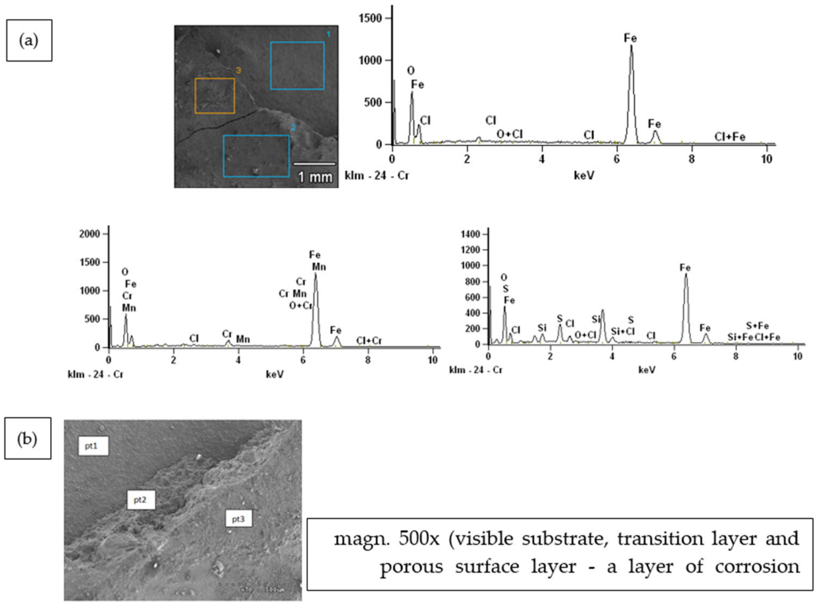
4.2. SEM Microscopy and Scanning Surface Analysis of Samples

In order to quantify the chemical composition of the surface layers on the material samples after exposure, EDS tests were performed, the results of which are presented in the form of diffraction patterns. The chemical composition of the layer was analyzed at points marked in the microscope photo. Diffractograms with a microscopic photo for all of the individual construction materials are presented in Figure 16, Figure 17, Figure 18, Figure 19, Figure 20, Figure 21, Figure 22 and Figure 23.

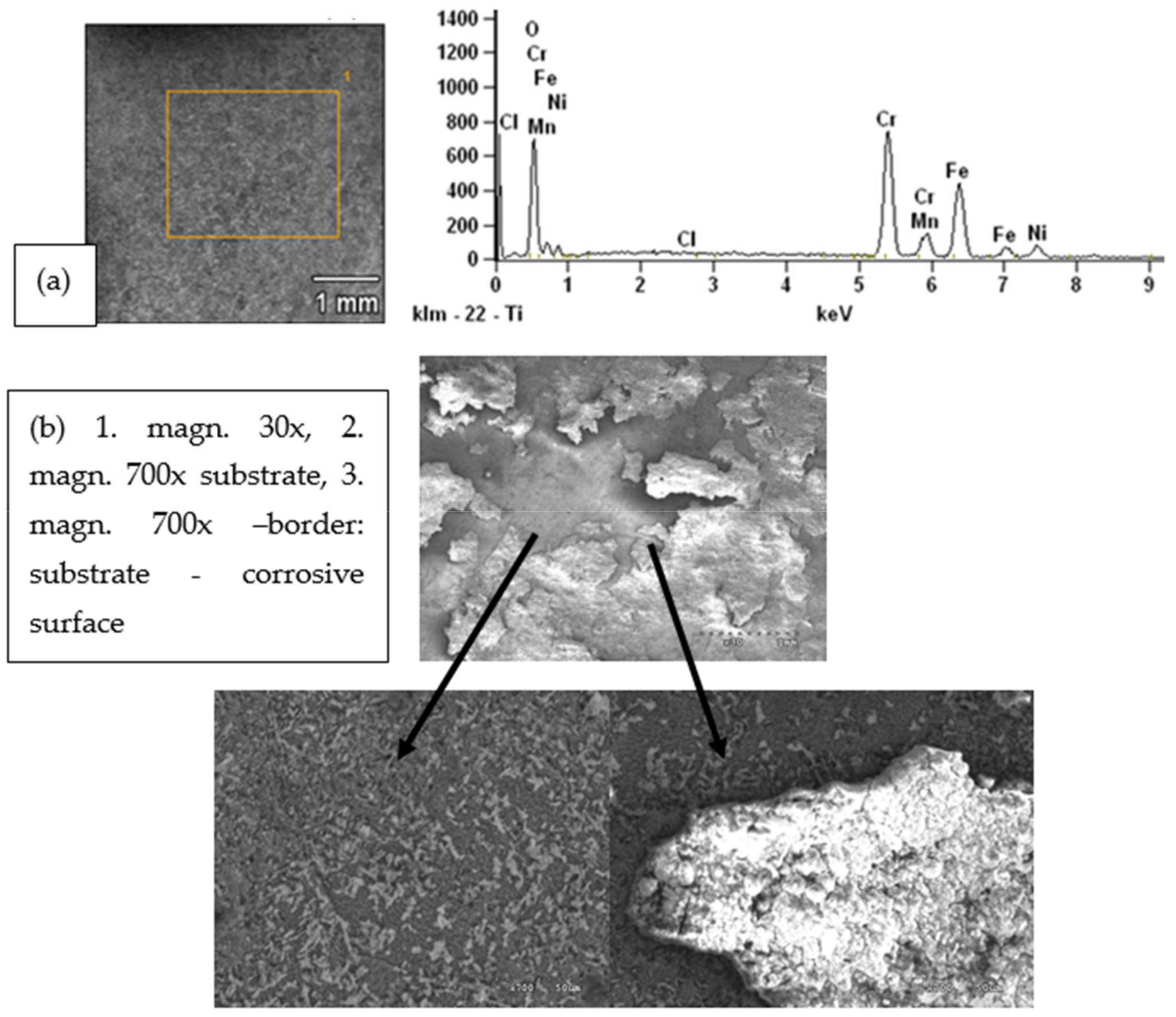
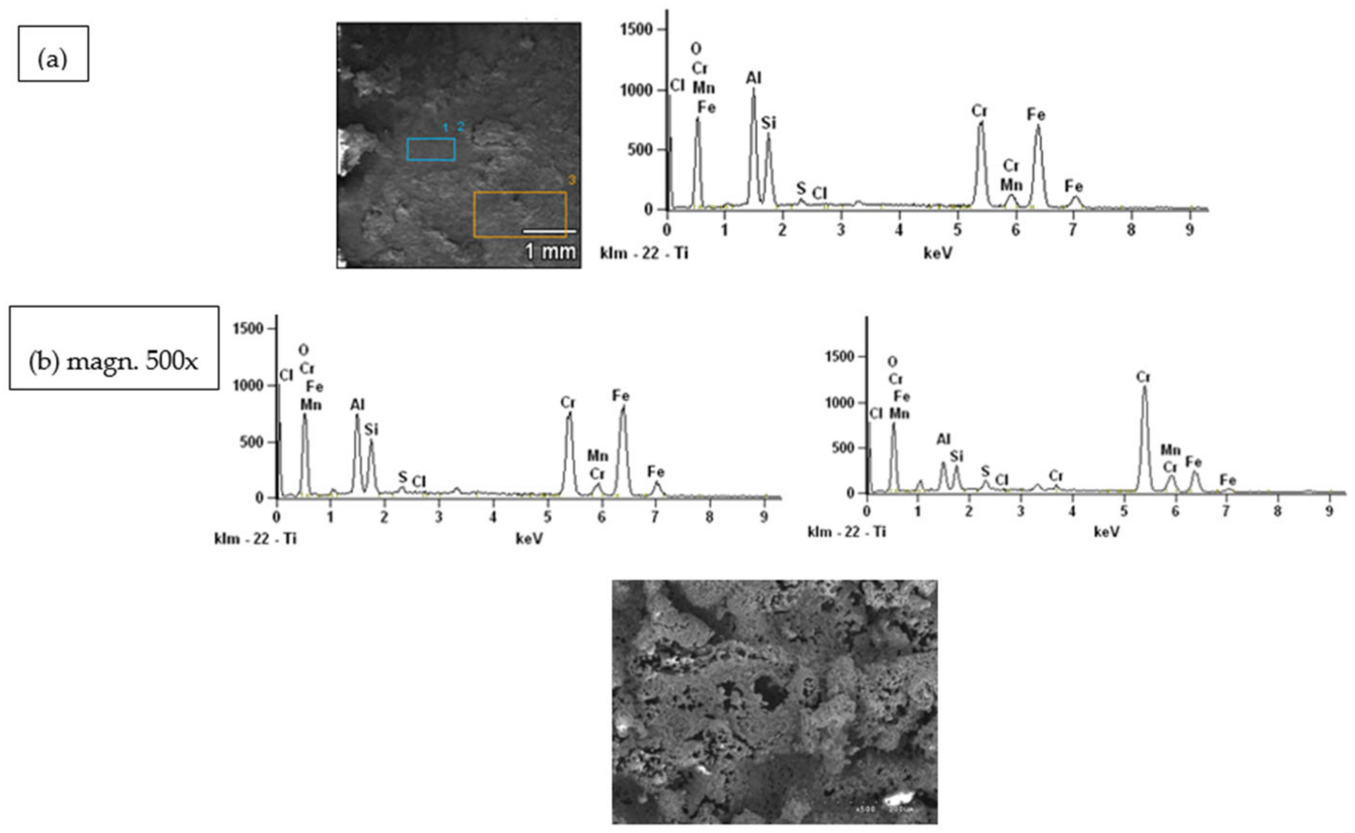
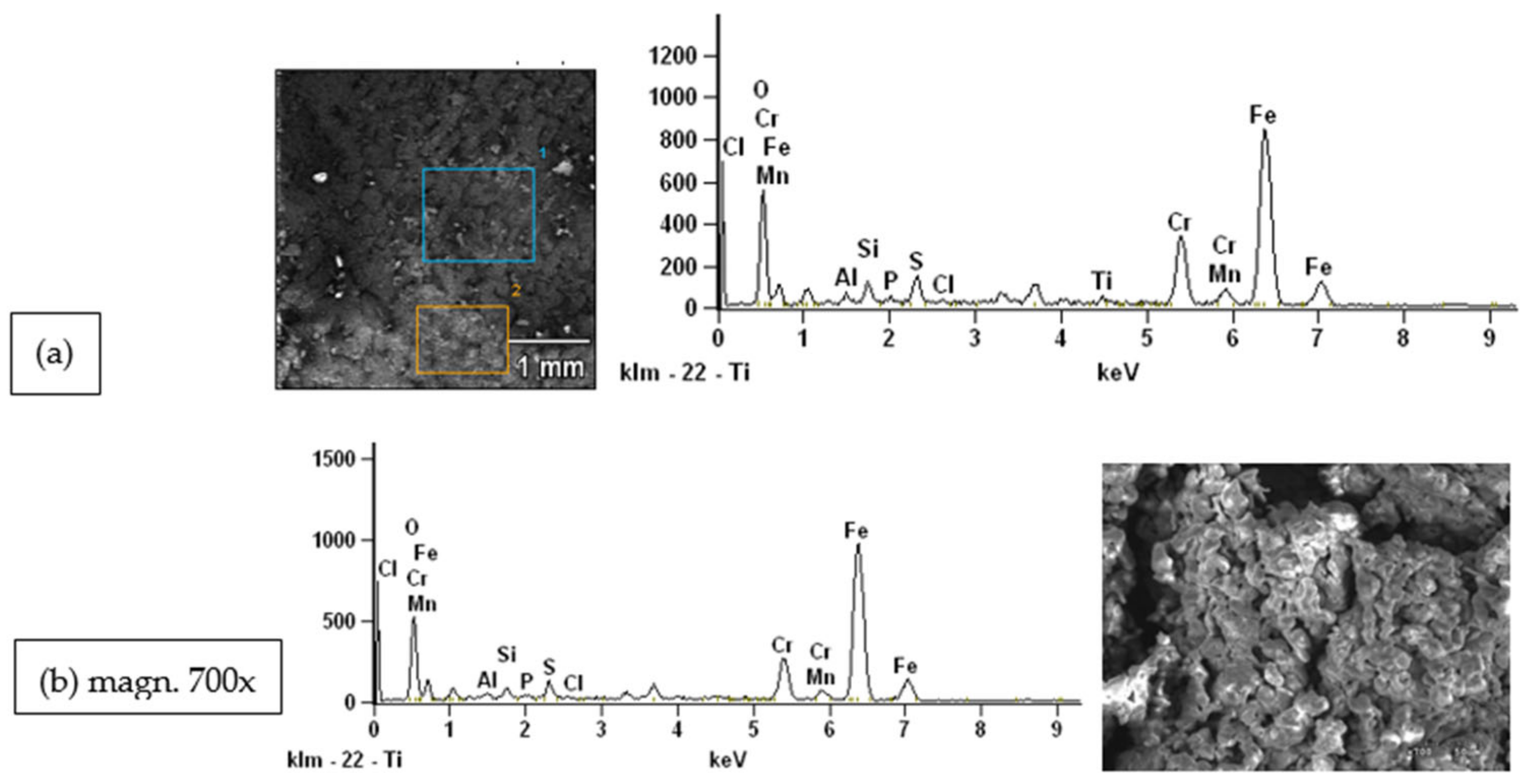
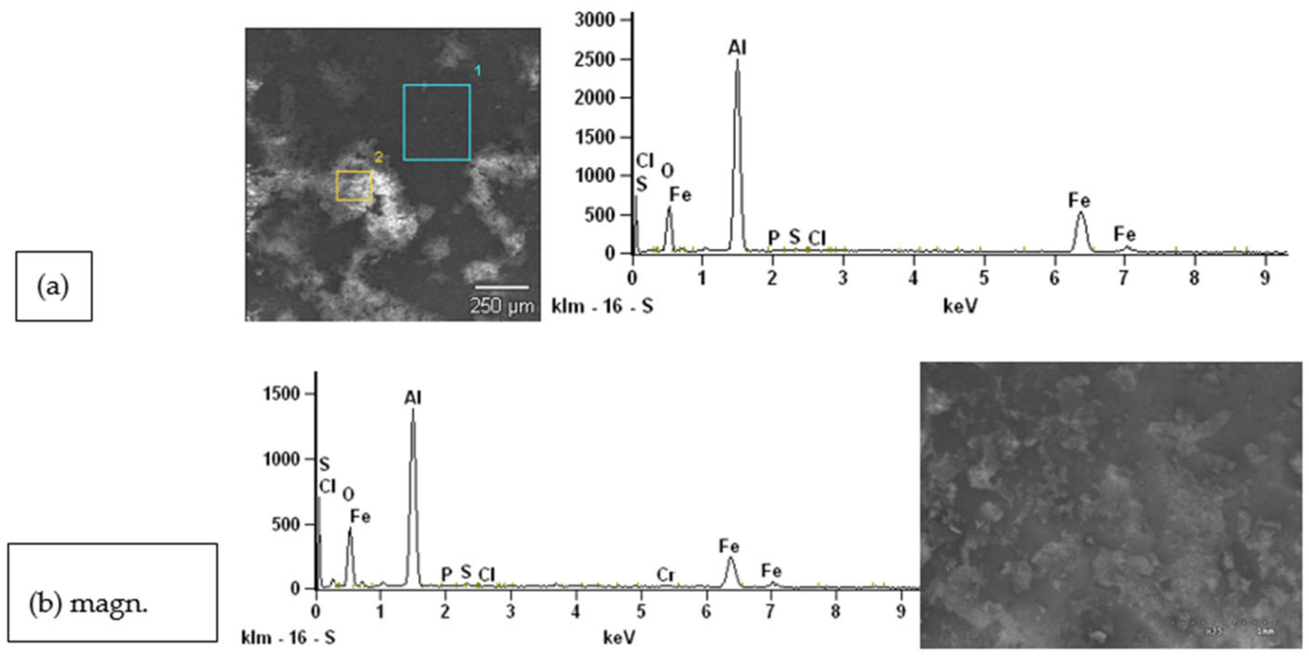
4.2.1. Steel Samples

The results (Figure 16, Figure 17, Figure 18 and Figure 19) shows that the layers consist mainly of oxides of those metals that are present in the samples (peaks in the diffraction patterns). The presence of sulfur and chlorine from the gas atmosphere in the combustion chamber was observed in the outer porous layers.
The outer porous surface layer of the St41K boiler steel was mainly composed of iron oxides with sulfur and chlorine contents; the oxygen fraction relates to metal oxides. Between the corrosion layer and the metal surface an intermediate layer of approximately 200 µm of pure iron oxide with a distinct crystal structure can be observed, the size of the crystallites being about 50 µm (Figure 16b). On the other hand, the metal surface was covered with a dense, brown layer of iron oxide with a small admixture of chlorine, which may indicate the diffusion of chlorine into metal through the layer of corrosion products. However, none of the described layers constituted a protective barrier for the steel. The presence of chlorine in layers pt1, pt2 and pt3 proves the diffusion of chlorine from pt3 and pt2 to pt1.
The layer of oxides on the 50H21G9N4 valve heat-resistant steel was compact and protected the steel surface against the corrosive environment (Figure 17), which indicates that the valve steel is best suited to work in the combustion chamber conditions of a household boiler fired with agricultural biomass.
In the areas designated 1 and 2 and separated in the microscope image, no significant presence of chlorine was observed among the corrosion products, as is indicated by the analysis of the chemical composition (Figure 18 and Figure 19).
Results based on laboratory furnace tests on alloys of interest to the waste-to-energy (WTE) industry were included in [33]. The test samples were samples cut from boiler tubes, and had an area of 3.2 cm2. The chemical environment was introduced into the electric furnace, which recreated a superheater tube furnace with a temperature range of 400–550 °C. The gas environment was formed by a stream of O2, CO2, H2O, HCl, SO2 and N2 gases. The influence of hydrogen chloride on SA178A, SA 213-T22 (2.5 Cr-1 Mo-Fe) and NSSER-4 (Fe-17Cr-13Ni) alloys was investigated. Changing the concentration from 400 ppm to 800 ppm at 500 °C increased the average weight loss by 17.5%, compared to a 60% increase from 0 to 400 ppm. For each alloy, the weight loss increased sharply between 450 °C and 500 °C. The effect of hydrogen chloride was milder for austenitic alloys compared to carbon steel or low alloy steel. In a comparative study between isothermal and temperature gradient tests, it was shown that the corrosion of SA178A was not affected by a temperature gradient up to 250 °C. It was found that the addition of 800 ppm of gaseous hydrogen chloride (HCl) to the mixed gases in an oxidizing environment accelerated the corrosion rate of SA178A (Fe-0.1C) at 500 °C, which was recorded by a change in the parabolic rate constant over a period of 72 h (from 0.18 to 1.7 μm2/h). This indicates that HCl accelerates corrosion through an active oxidation mechanism. Yacheng Liu et al. [36] conducted laboratory experiments in a tube furnace to estimate the degree of corrosion of various boiler steels under simulated conditions during the firing of high and low chlorine coals. The results showed that the stronger degradation of the material was due to the burning of high-chloride carbon at the higher temperature of the pipe walls, and that the corrosion resistance was the highest for the austenitic TP347H steel, which had the highest content of chromium and nickel.

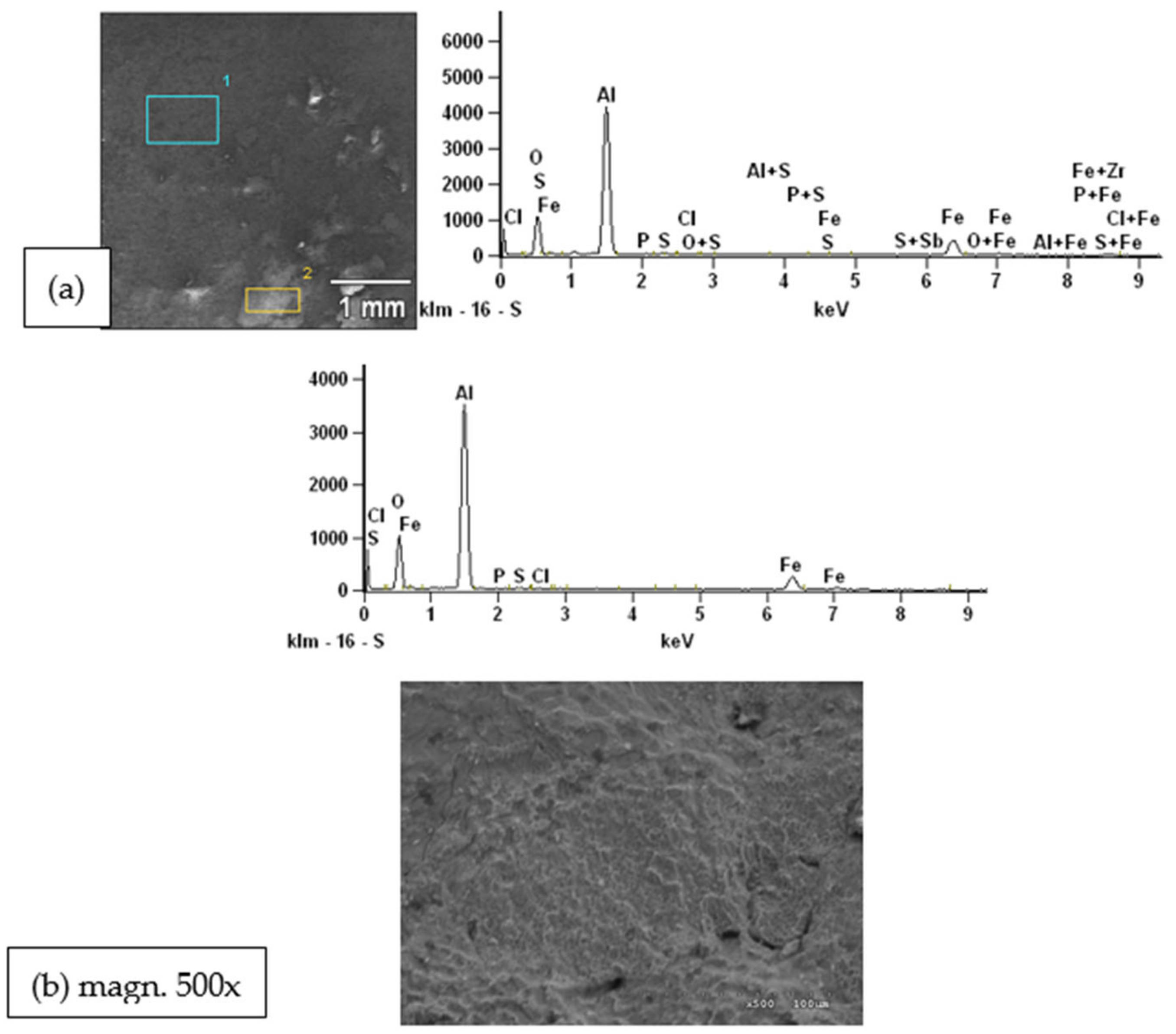
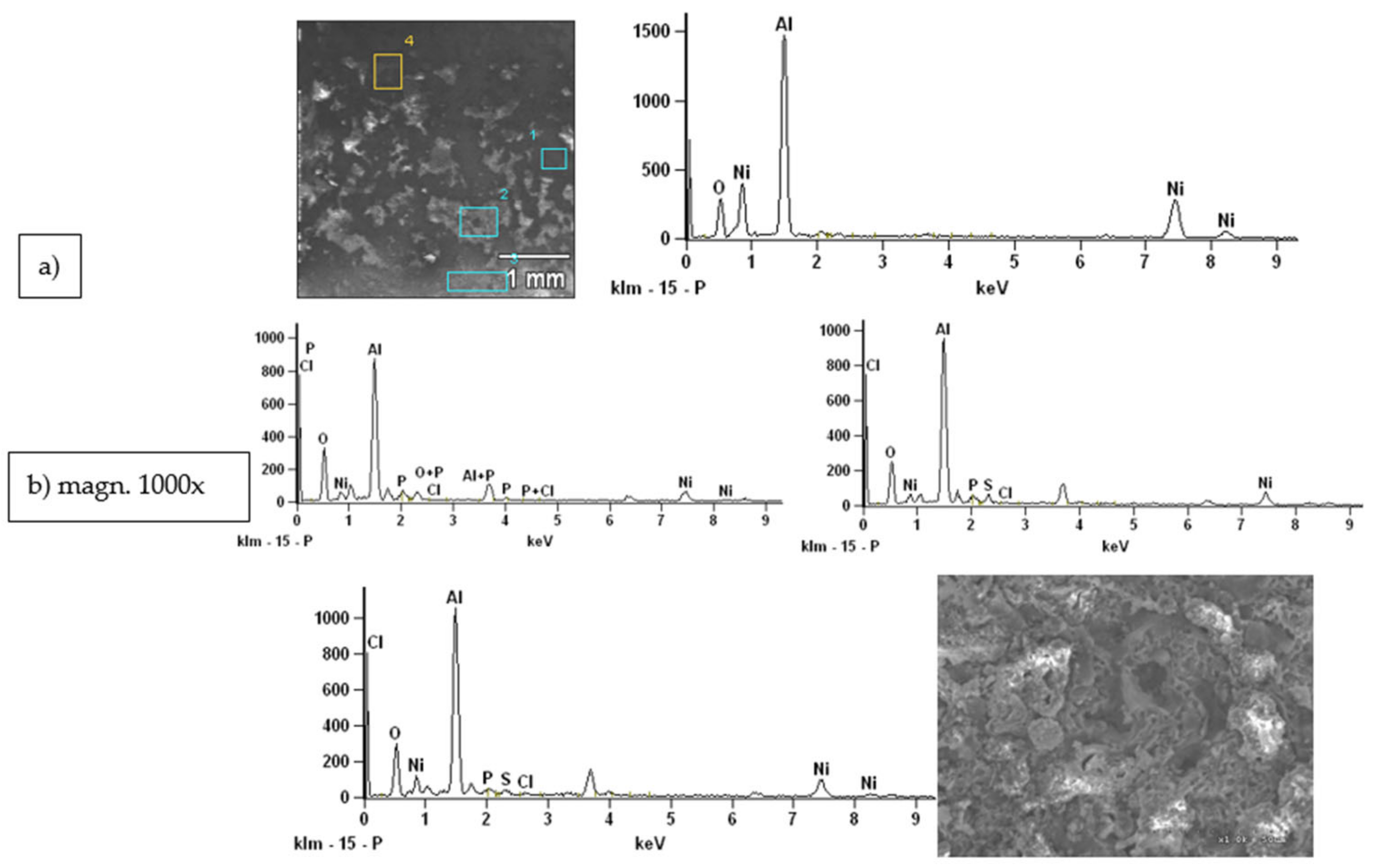
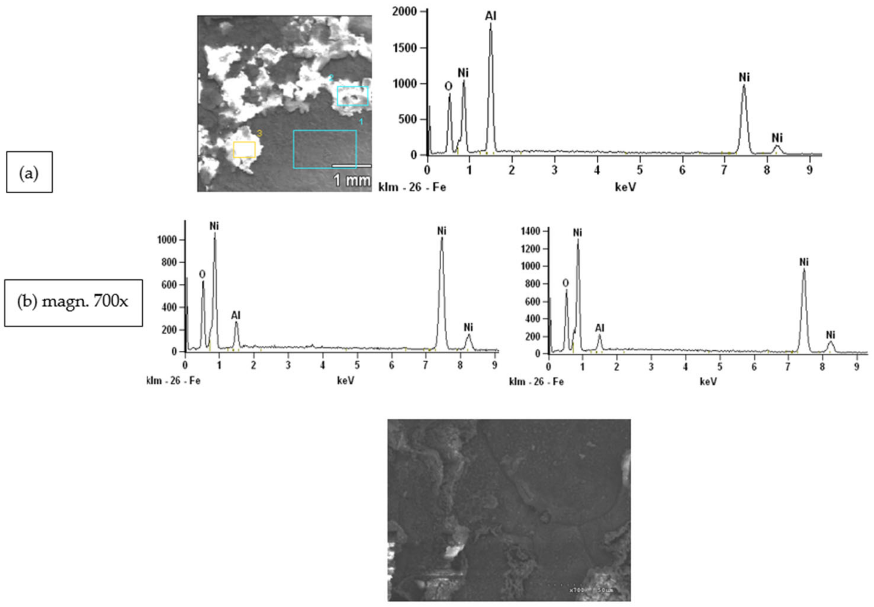
4.2.2. Intermetallic Alloy Samples

The results are shown in the Figure 20, Figure 21, Figure 22 and Figure 23. The scanning research charts show that intermetals are characterized by good corrosion resistance under the operating conditions of a domestic boiler for agricultural biomass. The analysis of the chemical composition of the surface of the samples shows the dominant share of aluminum oxide in the surface layers. In the case of samples of intermetallic materials based on the FeAl phase and Fe3Al phases, there are also iron oxides and trace amounts of gases from the chamber atmosphere. On the other hand, in materials based on the NiAl and Ni3Al phases, only nickel oxides are used, and the proportions of individual compounds depend on the test site, i.e., oxides adjacent to the metal surface are richer in nickel oxides, while the surface layers are richer in aluminum oxide.
In the case of all intermetals, despite the differences in the chemical composition of oxides, the good adherence of their compact structure to the metal surface effectively protects the materials against the aggressive action of the chlorine component of the gases (HCl or Cl2) in the combustion chamber. Therefore, it can be concluded that these materials are characterized by good resistance to the corrosive atmosphere, and can be used as construction materials in boilers burning agricultural biomass.

5. Conclusions

The current problem related to the construction of the steel elements of a domestic boiler lies in the selection of appropriate materials. Such materials must be heat-resistant and at the same time be resistant to the corrosive environment of chlorine and its compounds released during the combustion of biomass fuel. Resistance tests on four grades of steel and four types of intermetallic materials, all placed in the zone of the highest temperature of a 750–900 °C boiler furnace, where chlorine corrosion may appear, showed that:
  • St41K boiler steel is not suitable for operation under the assumed conditions, because it is significant corrosion;
  • H25T and H24JS heat-resistant steels and 50H21G9N4 heat-resistant steel are subject to slight corrosion;
  • 50H21G9N4 valve heat-resistant steel is best-suited to work in the assumed conditions;
  • Intermetallic materials based on the FeAl and Fe3Al phases and on the NiAl and Ni3Al phases are characterized by good corrosion resistance under the operating conditions of a domestic boiler for agricultural biomass;
  • The thin, dense top layer on the surfaces of the samples consisted mainly of alumina; this layer adheres well to the metal surface and effectively protects the materials against aggressive chlorine action.
The results of this research can be successfully used by boiler manufacturers in the selection of appropriate construction materials for boilers intended for the combustion of agro-biomass fuels.

Author Contributions

Conceptualization, D.K., S.P. and P.M.; Formal analysis, D.K. and S.P.; Methodology, D.K., S.P. and P.M.; Software, P.M. All authors have read and agreed to the published version of the manuscript.

Funding

Authors have received no external funding.

Data Availability Statement

Not applicable.

Acknowledgments

This research was funded by Research and development project R06 018 02—Caloric and emission tests of waste biomass as fuels for power boilers; Research work—WZ/WB-IIŚ/4/2019; Research work—3475/183/P (DBUPB/2020/005).

Conflicts of Interest

The authors declare no conflict of interest.

References

  1. Amiandamhen, S.O.; Adamopoulos, S.; Adl-Zarrabi, B.; Yin, H.; Norén, J. Recycling Sawmilling Wood Chips, Biomass Combustion Residues, and Tyre Fibres into Cement-Bonded Composites: Properties of Composites and Life Cycle Analysis. Constr. Build. Mater. 2021, 297, 123781. [Google Scholar] [CrossRef]
  2. Matalkah, F.; Soroushian, P.; Ul Abideen, S.; Peyvandi, A. Use of Non-Wood Biomass Combustion Ash in Development of Alkali-Activated Concrete. Constr. Build. Mater. 2016, 121, 491–500. [Google Scholar] [CrossRef] [Green Version]
  3. Zhao, N.; Li, B.; Ahmad, R.; Ding, F.; Zhou, Y.; Li, G.; Zayan, A.M.I.; Dong, R. Dynamic Relationships between Real-Time Fuel Moisture Content and Combustion-Emission-Performance Characteristics of Wood Pellets in a Top-Lit Updraft Cookstove. Case Stud. Therm. Eng. 2021, 28, 101484. [Google Scholar] [CrossRef]
  4. Guerrero, F.; Arriagada, A.; Muñoz, F.; Silva, P.; Ripoll, N.; Toledo, M. Particulate Matter Emissions Reduction from Residential Wood Stove Using Inert Porous Material inside Its Combustion Chamber. Fuel 2021, 289. [Google Scholar] [CrossRef]
  5. Ma, W.; Ma, C.; Liu, X.; Gu, T.; Thengane, S.K.; Bourtsalas, A.; Chen, G. Nox Formation in Fixed-Bed Biomass Combustion: Chemistry and Modeling. Fuel 2021, 290, 119694. [Google Scholar] [CrossRef]
  6. Archan, G.; Scharler, R.; Pölzer, L.; Buchmayr, M.; Sommersacher, P.; Hochenauer, C.; Gruber, J.; Anca-Couce, A. Detailed NOX Precursor Measurements within the Reduction Zone of a Novel Small-Scale Fuel Flexible Biomass Combustion Technology. Fuel 2021, 302, 121073. [Google Scholar] [CrossRef]
  7. Samae, H.; Tekasakul, S.; Tekasakul, P.; Furuuchi, M. Emission Factors of Ultrafine Particulate Matter (PM < 0.1 Μm) and Particle-Bound Polycyclic Aromatic Hydrocarbons from Biomass Combustion for Source Apportionment. Chemosphere 2021, 262, 127846. [Google Scholar] [CrossRef] [PubMed]
  8. Namkung, H.; Park, J.H.; Lee, Y.J.; Song, G.S.; Choi, J.W.; Park, S.J.; Kim, S.; Liu, J.; Choi, Y.C. Performance Evaluation of Biomass Pretreated by Demineralization and Torrefaction for Ash Deposition and PM Emissions in the Combustion Experiments. Fuel 2021, 292, 120379. [Google Scholar] [CrossRef]
  9. Sobieraj, J.; Gądek, W.; Jagodzińska, K.; Kalisz, S. Investigations of Optimal Additive Dose for Cl-Rich Biomasses. Renew. Energy 2021, 163, 2008–2017. [Google Scholar] [CrossRef]
  10. Wang, Q.; Chen, J.; Han, K.; Wang, J.; Lu, C. Influence of BaCO3 on Chlorine Fixation, Combustion Characteristics and KCl Conversion during Biomass Combustion. Fuel 2017, 208, 82–90. [Google Scholar] [CrossRef]
  11. Król, D.; Borsukiewicz Gozdur, A.; Poskrobko, S. The Study of Waste Wood Biomass as a Biofuel in the Context of Boiler Operational Problems—Slagging and High-Temperature Corrosion. Drewno 2016, 59, 257–264. [Google Scholar] [CrossRef]
  12. Oris, C.; Luo, Z.; Zhang, W.; Yu, C. Forms of Potassium and Chlorine from Oxy-Fuel Co-Combustion of Lignite Coal and Corn Stover. Carbon Resour. Convers. 2019, 2, 103–110. [Google Scholar] [CrossRef]
  13. Niemi, J.; Engblom, M.; Laurén, T.; Yrjas, P.; Lehmusto, J.; Hupa, M.; Lindberg, D. Superheater Deposits and Corrosion in Temperature Gradient—Laboratory Studies into Effects of Flue Gas Composition, Initial Deposit Structure, and Exposure Time. Energy 2021, 228, 120494. [Google Scholar] [CrossRef]
  14. Balint, R.; Engblom, M.; Niemi, J.; Silva da Costa, D.; Lindberg, D.; Yrjas, P.; Hupa, L.; Hupa, M. Temperature Gradient Induced Changes within Superheater Ash Deposits High in Chlorine. Energy 2021, 226, 120439. [Google Scholar] [CrossRef]
  15. Oksa, M.; Auerkari, P.; Salonen, J.; Varis, T. Nickel-Based HVOF Coatings Promoting High Temperature Corrosion Resistance of Biomass-Fired Power Plant Boilers. Fuel Process. Technol. 2014, 125, 236–245. [Google Scholar] [CrossRef]
  16. Dedov, A.; Klevtsov, I.; Lausmaa, T.; Bojarinova, T. High Temperature Corrosion and Remaining Lifetime Assessment of Ferritic Steel 13CrMo4-4 Tubes in a Convective Superheater of a CFB Oil Shale Boiler. Corros. Sci. 2020, 164, 108311. [Google Scholar] [CrossRef]
  17. Zhang, C.; Bai, L.; Yao, Q.; Li, J.; Wang, H.; Shen, L.; Sippula, O.; Yang, J.; Zhao, J.; Liu, J.; et al. Emission Characteristics of Polychlorinated Dibenzo-p-Dioxins and Dibenzofurans from Industrial Combustion of Biomass Fuels. Environ. Pollut. 2022, 292, 118265. [Google Scholar] [CrossRef] [PubMed]
  18. Poskrobko, S.; Łach, J.; Król, D. Experimental Investigation of Hydrogen Chlorine Bonding with Limestone and Dolomite in the Furnace of a Stoker-Fired Boiler. Energy Fuels 2010, 24, 5851–5858. [Google Scholar] [CrossRef]
  19. Poskrobko, S.; Łach, J.; Król, D. Experimental investigation of hydrogen chloride bonding with calcium hydroxide in the furnace of a stoker-fired boiler. Energy Fuels 2010, 3, 1948–1957. [Google Scholar] [CrossRef]
  20. Król, D.; Poskrobko, S. Transformations, Threats and the Bond of Chlorine in the Processes of Burning the Wastes. EPJ Web Conf. 2019, 213, 02046. [Google Scholar] [CrossRef]
  21. Uusitalo, M.A.; Vuoristo, P.M.J.; Mäntylä, T.A. High Temperature Corrosion of Coatings and Boiler Steels in Oxidizing Chlorine-Containing Atmosphere. Mater. Sci. Eng. A 2003, 346, 168–177. [Google Scholar] [CrossRef]
  22. Wan, K.; Wang, Z.; Xia, J.; Vervisch, L.; Domingo, P.; Lv, Y.; Liu, Y.; He, Y.; Cen, K. Numerical Study of HCl and SO2 Impact on Potassium Emissions in Pulverized-Biomass Combustion. Fuel Process. Technol. 2019, 193, 19–30. [Google Scholar] [CrossRef] [Green Version]
  23. Ren, X.; Sun, R.; Chi, H.H.; Meng, X.; Li, Y.; Levendis, Y.A. Hydrogen Chloride Emissions from Combustion of Raw and Torrefied Biomass. Fuel 2017, 200, 37–46. [Google Scholar] [CrossRef]
  24. Li, L.; Duan, Y.; Cao, Y.; Chu, P.; Carty, R.; Pan, W.P. Field Corrosion Tests for a Low Chromium Steel Carried out at Superheater Area of a Utility Boiler with Three Coals Containing Different Chlorine Contents. Fuel Process. Technol. 2007, 88, 387–392. [Google Scholar] [CrossRef]
  25. Fantozzi, D.; Matikainen, V.; Uusitalo, M.; Koivuluoto, H.; Vuoristo, P. Chlorine Induced High-Temperature Corrosion Mechanisms in HVOF and HVAF Sprayed Cr3C2-Based Hardmetal Coatings. Corros. Sci. 2019, 160, 108166. [Google Scholar] [CrossRef]
  26. Song, B.; Voisey, K.T.; Hussain, T. High Temperature Chlorine-Induced Corrosion of Ni50Cr Coating: HVOLF, HVOGF, Cold Spray and Laser Cladding. Surf. Coat. Technol. 2018, 337, 357–369. [Google Scholar] [CrossRef]
  27. Abu-warda, N.; Tomás, L.M.; López, A.J.; Utrilla, M.V. High Temperature Corrosion Behavior of Ni and Co Base HVOF Coatings Exposed to NaCl-KCl Salt Mixture. Surf. Coat. Technol. 2021, 418, 127277. [Google Scholar] [CrossRef]
  28. Król, D. Biomass and Fuels Formed from Waste in Low Emission Combustion Technologies; Publishing House Silesian University of Technology: Gliwice, Poland, 2013. [Google Scholar]
  29. Motyl, P.; Król, D.; Poskrobko, S.; Juszczak, M. Numerical Modelling and Experimental Verification of the Low-Emission Biomass Combustion Process in a Domestic Boiler with Flue Gas Flow around the Combustion Chamber. Energies 2020, 13, 5837. [Google Scholar] [CrossRef]
  30. Liu, Y.; Fan, W.; Wu, X.; Zhang, X. Chlorine-Induced High-Temperature Corrosion of Boiler Steels Combusting Sha Erhu Coal Compared to Biomass. Energy Fuels 2018, 32, 4237–4247. [Google Scholar] [CrossRef]
  31. Persdotter, A.; Boll, T.; Jonsson, T. Minor Element Effect on High Temperature Corrosion of a Low-Alloyed Steel: Insight into Alkali- and Chlorine Induced Corrosion by Means of Atom Probe Tomography. Corros. Sci. 2021, 192, 109779. [Google Scholar] [CrossRef]
  32. Uusitalo, M.A.; Vuoristo, P.M.J.; Mäntylä, T.A. High Temperature Corrosion of Coatings and Boiler Steels below Chlorine-Containing Salt Deposits. Corros. Sci. 2004, 46, 1311–1331. [Google Scholar] [CrossRef]
  33. Sharobem, T.T. Mitigation of High Temperature Corrosion in Waste-to-Energy Power Plants. Ph.D. Thesis, Columbia Univiversity, Columbia, OH, USA, 2016; pp. 1–144. [Google Scholar]
  34. Wu, D.; Liu, S.; Yuan, Z.; Cao, P.; Wei, X.; Zhang, C. Influence of Water Vapor on the Chlorine-Induced High-Temperature Corrosion Behavior of Nickel Aluminide Coatings. Corros. Sci. 2021, 190, 109689. [Google Scholar] [CrossRef]
  35. Chi, H.; Pans, M.A.; Bai, M.; Sun, C.; Hussain, T.; Sun, W.; Yao, Y.; Lyu, J.; Liu, H. Experimental Investigations on the Chlorine-Induced Corrosion of HVOF Thermal Sprayed Stellite-6 and NiAl Coatings with Fluidised Bed Biomass/Anthracite Combustion Systems. Fuel 2021, 288, 119607. [Google Scholar] [CrossRef]
  36. Liu, Y.; Fan, W.; Zhang, X.; Wu, X. High-Temperature Corrosion Properties of Boiler Steels under a Simulated High-Chlorine Coal-Firing Atmosphere. Energy Fuels 2017, 31, 4391–4399. [Google Scholar] [CrossRef]
Figure 1. Barley straw pellets.
Energies 15 00382 g001
Figure 2. Temperature distribution [K].
Energies 15 00382 g002
Figure 3. (a) O2 concentration [%]; (b) CO concentration [%].
Energies 15 00382 g003
Figure 4. Temperature distribution [K].
Energies 15 00382 g004
Figure 5. (a) O2 concentration [%]; (b) CO concentration [%].
Energies 15 00382 g005
Figure 6. View of the boiler: (a) The boiler on the test stand; (b) Combustion chamber with marked key levels for further analysis of the results.
Energies 15 00382 g006
Figure 7. Dimensions of steel samples.
Energies 15 00382 g007
Figure 8. Photos of samples of the St41K boiler steel after exposure in the combustion chamber of the boiler: (a) a layer of porous corrosion products; (b) exposure of the substrate.
Energies 15 00382 g008
Figure 9. Photo of the 50H21G9N4 steel sample after exposure in the boiler combustion chamber.
Energies 15 00382 g009
Figure 10. Photo of a sample of H24JS steel after exposure in the boiler combustion chamber.
Energies 15 00382 g010
Figure 11. Photo of the H25T steel sample after exposure in the boiler combustion chamber.
Energies 15 00382 g011
Figure 12. Photo of the FeAl intermetal sample after exposure in the boiler combustion chamber.
Energies 15 00382 g012
Figure 13. Photo of the Fe3Al intermetal sample after exposure in the boiler combustion chamber.
Energies 15 00382 g013
Figure 14. Photo of the NiAl intermetal sample after exposure in the boiler combustion chamber.
Energies 15 00382 g014
Figure 15. Photo of the Ni3Al intermetal sample after exposure in the boiler combustion chamber.
Energies 15 00382 g015
Figure 16. (a) The chemical composition of the surface of the St41K boiler steel in the planes pt1, pt2 and pt3 on the microscopic photo; (b) microscopic photo (SEM) of the surface of the St41K boiler steel.
Energies 15 00382 g016
Figure 17. (a) The chemical composition of the 50H21G9N4 valve steel surface in the pt1 surface in the microscopic photo; (b) microscopic photo (SEM) of the surface of the St41K boiler steel.
Energies 15 00382 g017
Figure 18. (a) Chemical composition of the surface of heat-resistant steel H24JS in planes pt1, pt2 and pt3; (b) microscopic photo (SEM) of the surface of H24JS heat-resistant steel.
Energies 15 00382 g018
Figure 19. (a) Chemical composition of the surface of heat-resistant steel H25T in planes pt1 and pt2; (b) microscopic photo (SEM) of the surface of H25T heat-resistant steel.
Energies 15 00382 g019
Figure 20. (a) Chemical composition of the FeAl intermetal surface in the pt1 and pt2 surfaces; (b) microscopic photo (SEM) of the FeAl intermetal surface.
Energies 15 00382 g020
Figure 21. (a) Chemical composition of the Fe Al intermetal surface in the pt1 and pt2 planes; (b) microscopic photo (SEM) of the Fe3Al intermetal surface.
Energies 15 00382 g021
Figure 22. (a) Chemical composition of the NiAl intermetal surface in planes pt1, pt2, pt3 and pt4; (b) microscopic photo (SEM) of NiAl intermetal surface.
Energies 15 00382 g022
Figure 23. (a) Chemical composition of the Ni3Al intermetal surface in planes pt1, pt2 and pt3; (b) microscopic photo (SEM) of the Ni3Al.
Energies 15 00382 g023
Table 1. Eutectics—melting point.
Composition [% by Mass]Melting Point [°C]
48 ZnCl2 52 KCl250
79 PbCl2 21 KCl411
69 PbCl2 31 NaCl410
39 ZnCl2 50 KCl 11 PbCl2275
35 ZnCl2 48 NaCl 17 PbCl2350
Table 2. Fuel properties: moisture content, ash content A and elementary composition of dry mass fuel, LHV fuel calorific value.
Biomass FuelMoisture ContentCHO NSClALHV
[%][%][%][%][%][%][%][%][kJ/kg]
Barley straw7.346.735.9641.160.580.100.524.9516834
Table 3. The content of alkali metals (ppm) in the dry weight of the fuel.
Biomass FuelAlkali Metals
CaKNa
Barley straw516212933174
Table 4. Thickness h of samples, which were steel plates, depending on the type of material.
Steel GradeSample Thickness h [mm]
St41K3.5
50H21G9N44.0
H24JS4.5
H25T5.0
Publisher’s Note: MDPI stays neutral with regard to jurisdictional claims in published maps and institutional affiliations.

