Article

Iodide Electrolyte-Based Hybrid Supercapacitor for Compact Photo-Rechargeable Energy Storage System Utilising Silicon Solar Cells

by
Magdalena Skunik-Nuckowska
1,*,
Patryk Rączka
1,
Justyna Lubera
1,
Aleksandra A. Mroziewicz
1,
Sławomir Dyjak
2,
Paweł J. Kulesza
1,
Ireneusz Plebankiewicz
3,
Krzysztof A. Bogdanowicz
3 and
Agnieszka Iwan
3
1
Faculty of Chemistry, University of Warsaw, Pasteura 1, 02-093 Warsaw, Poland
2
Institute of Chemistry, Military University of Technology, Kaliskiego 2, 00-908 Warsaw, Poland
3
Military Institute of Engineer Technology, Obornicka 136 Str., 50-961 Wroclaw, Poland
*
Author to whom correspondence should be addressed.
Energies 2021, 14(9), 2708; https://doi.org/10.3390/en14092708
Submission received: 14 April 2021 / Revised: 27 April 2021 / Accepted: 4 May 2021 / Published: 9 May 2021
(This article belongs to the Special Issue Energy Security - Sociological and Technical Aspects and Innovations)

Abstract

:
The one of the most important issues in constructing light-harvesting photovoltaic (PV) systems with a charge storage element is its reliable and uninterrupted use in highly variable and weather-dependent conditions in everyday applications. Herein, we report the construction and applicability evaluation of a ready-to-use portable solar charger comprising a silicon solar cell and an enhanced energy hybrid supercapacitor using activated carbon electrodes and iodide-based aqueous electrolyte to stabilise the PV power under fluctuating light conditions. The optimised electrode/electrolyte combination of a supercapacitor was used for the construction of a 60 F/3 V module by a proper adjustment of the series and parallel connections between the CR2032 coin cells. The final photo-rechargeable device was tested as a potential supporting system for pulse electronic applications under various laboratory conditions (temperature of 15 and 25 °C, solar irradiation of 600 and 1000 W m−2).

1. Introduction

Current population growth and scarce natural resources compel searching for new, eco-friendly and renewable energy solutions [1]. With an upper hand in energy production, over traditional technologies, come photovoltaics, using indefinite power source which is the sun. The bottleneck of photovoltaic technology is the impossibility to generate the electric energy on the same level during the whole time of the exploitation; the light-harvesting process depends on the intensity and the availability of sunlight during sunshine hours. The solution to profit the most from short light availability is the storage of the electric energy in the form of electrochemical processes, allowing its later use during, for example, night hours [2,3]. In literature [3,4,5] some research has been done in assessing and building energy block storage systems based on supercapacitors (or more precisely, electrochemical double-layer capacitors, EDLC) due to their advantages such as a long durability (even up to 10 years with efficiencies at level of 95%), insensitivity to deep discharge/overcharge and power densities in the range of 10,000 W kg−1. Although supercapacitors offer tremendous power performance, the energy stored per mass or volume of the cell is much lower with respect to conventional batteries due to the pure electrostatic operation mechanism, like charging-discharging of the electrical double layer [6,7].
Among the recent attempts to improve the energy density of supercapacitors, the strategy of aqueous redox electrolyte hybrid energy storage (REHES) has received a significant attention due to the simplicity of the system’s construction, low cost of electrode materials/electrolyte and environmental friendliness [8,9,10]. In general, the aqueous-redox system exhibits a mixed charge–discharge mechanism; the charge is stored in the electrical double layer at the porous carbon/electrolyte interface, and also as a result of localised valence electron transfer due to the presence of electroactive redox couple in the electrolyte. The majority of REHES systems operate in the presence of electroactive species in aqueous, or mild aqueous-organic solutions, with the performance for some of them approaching or even exceeding the commercial organic systems [11,12,13,14,15,16]. The one of the most widely studied and most promising redox electrolytes based on alkali metal iodides [11,17,18,19,20,21,22] showed, the capacitance and energy increase attributed to: (i) The Faradaic charge transfer between I and I2/In, where n can be equal to 3 or 5, causing a significant rise to the total charge stored in the positive electrode of the REHES system; (ii) high operating voltage in aqueous electrolyte (up to 1.5 V) but still beyond the thermodynamic window of water decomposition, due to the high overpotential of hydrogen evolution in aqueous neutral media; (iii) lower self-discharge rate with respect to other REHES-type devices, due to the strong confinement of reaction products (I2, I3, I5) in pores (in particular micropores < 2 nm) of electrode materials [23,24].
In this paper iodide-based REHES system is for the first time used for the construction of 60 F/3 V module, designed to be coupled with the commercial silicon photovoltaic (PV) panel to form a single power supply unit insensitive to the fluctuation of sunlight power and weather conditions. Prior to the module construction, a series of activated carbon materials with different porosity, have been investigated in the presence of iodides in the laboratory test cells in order to select the optimal carbon material for the construction of a prototype.
In our previous work [25] we investigated three architectures of photo-rechargeable electric-energy storage systems based on silicon solar cells and commercially available supercapacitors achieving a total energy conversion from solar panel of 93%. Based on our past experience and developed engineering concept, here we propose for the first time, to the best of our knowledge, a new device based on REHES-type supercapacitors and specially tailored silicon solar cell module. To find the best silicon solar cells, two types of PV modules’ architectures were investigated in the constructed prototypes: fabricated from 10 silicon photovoltaic cells with size 50 mm × 20 mm connected in series and 2 silicon photovoltaic cells with size 70 mm × 50 mm connected in parallel. The study in this scope of work included: (i) Assembly of surface-mount device (SMD) components, including the current source block, voltage control system and supercapacitor charging system on a printed circuit board (PCB) based on a schematic diagram presented in Supplementary Figure S1; (ii) diagnostic measurements of the current-voltage characteristics of PV modules; (iii) making internal connections in supercapacitor module; (iv) measurements of charging, discharging and recharging characteristics of REHES-type supercapacitor implemented into the charger model.
To the best of our knowledge, it is the first paper presenting the possibility of practical use of a new hybrid redox electrolyte-based supercapacitor towards the construction of a ready-to-use portable solar charger. For this reason, we divided the paper into two sections, where in the first one the materials concept for hybrid supercapacitor construction is presented and investigated in detail, while in the second part the device based on new supercapacitors and silicon solar cells is described and investigated under various conditions towards practical use.

2. Materials and Methods

2.1. Preparation and Characterisation of Iodide Electrolyte-Based Supercapacitors

The activated carbon (AC) electrodes were prepared as 200 ± 10 µm free-standing discs of 10 mm in diameter. The following carbon materials were used: Norit SX2 (Polish Chemical Reagents, POCH, Gliwice, Poland), Norit B Eur (Cabot Corp., Boston, MA, USA), YP-50F and YP-80F (Kuraray Co., Tokyo, Japan). Norit SX2 material was additionally subjected to KOH activation using mAC/mKOH ratio equal to 1:2 and 1:4 [26]. The materials are further labelled as AC-1–AC-6.
For the electrodes preparation, 90 wt% of AC, 5 wt% of carbon conductive additive C65 (Imerys Graphite&Carbon, Bironico, Switzerland) and 5 wt% of PTFE (60 wt% dispersion in H2O, Sigma Aldrich, Munich, Germany) were mixed with ethanol in an agate mortar until the solvent evaporated. A few drops of hexane were in the next step added to the mixture, to make it more plastic. A received rubber-like material was rolled-pressed using a hot-rolling press (TMAXCN). The electrodes of 1 cm in diameter (thickness: 200 ± 5 µm) were punched from the resulting sheet using a manual die punching cutter and dried under vacuum at 120 °C. The average activated carbon mass loading in each electrode ranged from 7.2 to 12.2 mg cm−2 depending on the material density. The porosity parameters of the materials were characterised using N2 adsorption–desorption measurements at 77 K (ASAP 2060 Instrument, Micromeritics, Norcros, GA, USA); the protocol details were previously described [26].
The electrochemical tests were performed using Biologic VMP-3 workstation at room temperature (24 ± 1 °C). The laboratory measurement cells were composed of modified PFA Swagelok® fittings (1/2 in.) and two 316 L stainless-steel current collectors (diameter: 13 mm). Some experiments were performed in the three-electrode setup using T-shaped PFA Swagelok® union to enable measurements in the presence of the reference electrode (Hg/HgSO4/KCl(sat), Lambda System). Prior assembly, the AC electrodes and the separator (Celgard® 3501, thickness: 25 µm) were pre-wetted with the electrolyte (0.5 mol dm−3 KI in 0.5 mol dm−3 K2SO4) for 15 min and the electrolyte excess was gently squeezed out prior assembly in the measurement cell. The electrochemical tests in the three-electrode cell were performed following injection of additional 400 µL of electrolyte, through the upper hole of Swagelok® connector, before inserting the reference electrode.
The test protocol for each cell included: (i) 50 cyclic voltametric (CV) cycles at 0.05 V s−1, (ii) single voltametric cycle at 0.005 V s−1, (iii) galvanostatic charge-discharge with potential limitation (GCPL) from 0.1 A g−1 to 20 A g−1 (normalised per mass of both electrodes), (iv) open-circuit voltage measurement following galvanostatic charging at 1 A g−1. The gravimetric parameters (capacitance and energy) were calculated using the rules advised for the REHES-type systems [8,27] and normalised against dry mass of both electrodes (C, E) or the total mass of the device (C*, E*), excluding outer housing.
In order to determine the electrolyte mass present in the cell, dry and pre-wetted electrodes and a separator were weighted with care taken to gently remove any excess electrolyte with a tissue. Additionally, a protocol applied elsewhere [13,28] was used and involved: (i) Determination of the free volume in carbon electrodes serving as a reservoir for the electrolyte as: V f r e e = V g e o m e d , where Vgeo—the geometric volume of the electrodes, me—the mass of the electrodes, d—the skeletal density of carbon equal to 2.1 g cm−3; (ii) determination of the Vfree in the separator: V f r e e _ s e p = V g e o _ s e p · P s e p , where Psep—the porosity of the separator equal to 0.55 for Celgard 3501; (iii) calculation of the electrolyte mass: m e l = ( V f r e e + V f r e e s e p ) · d e l , where del—density of the electrolyte (1.15 g cm−3). The difference in the electrolyte mass determined using empirical and theoretical approach ranged from 0.2 to 4.0%.

2.2. Energy Storage and Conversion Elements of Integrated Photo-Rechargeable System

The supercapacitor module for the construction of a solar charger consisted of three printed circuit boards with a space for parallel connected CR2032 coin cell holders. Each coin cell was fabricated using manual crimping machine (GN-CC20, Gelon Lib, Shandong, China) and contained two series-connected AC-6/KI-REHES supercapacitors separated with a stainless steel spacer. The area and thickness of each electrode were equal to 1.77 cm2 and 200 ± 10 µm, respectively. The total AC mass loading in the cell was equal to 32.4 ± 0.2 mg cm−2. The total number of CR2032 cells in the module was equal to 126.
The SS150AAA solar radiation simulator coupled with the IV Tracer SS IV CT-02 system and Keithley Sourcemeter SM2401 was used for measuring the IV characteristic of commercial solar elements (Figure S2). Silicon solar cells used in the study were received from Soltec and RS Components (Warszawa, Poland).

3. Discussion

3.1. Activated Carbon Selection for the Construction of Supercapacitor Module—General Studies

The AC materials with different specific surface area (SBET) and total pore volume (Vt) have been used in the preliminary electrochemical tests in order to select an adequate material for the supercapacitor module construction. The differences in the porosity characteristics are illustrated in Figure S3 and Table S1. As it can be seen, the materials exhibited mixed micro-mesoporous character with different contribution of the mesoporosity and different PSD in the micropore and small mesopore range. The SBET, Vt and the average micropore size (L0) of the materials were in the range of 789–2607 m2 g−1, 0.56–1.44 m3 g−1 and 0.9–1.6 nm, respectively.
Figure 1a shows the CV profiles for two-electrode Swagelok® cells testing system in the voltage window of 1.5 V based on previous works for the KI-REHES systems [23,29]. It is important to notice that the AC-2 and AC-5 carbon-based cells exhibited a clear low-voltage peak, less pronounced for other carbons.
It is associated with the fact that during charging the transition between the reactant (I) and the reaction products (I2, I3 and higher polyiodides) occurs near the potential of E0V, the equal potential of both electrodes at discharge state. The E0V for the AC-2 and AC-5-based cells measured at 0.1 A g−1 vs. Hg/HgSO4 reference electrode was equal to −0.29 ± 0.01 V, while for other carbon materials the more negative values of −0.34 ± 0.01 V were observed. In other words, during charge–discharge process the potential range of the iodides’ redox activity is shared between the ACs electrodes in a different way. It is exemplified for the AC-2 and AC-3-based REHES systems in Figure S4. A characteristic plateau in the potential range of the negative electrode near E0V in Figure S4b was consistent with the electroactivity of iodides (reduction of I2 and In) during charging, and subsequent oxidation during discharging, in addition to the main Faradaic processes taking place at the positive electrode (Figure S4d). This phenomenon explains the origin of a low-voltage signal at the CV curve for the AC-2-type supercapacitor (Figure 1a), which on the contrary, was not present for the AC-3 material. The AC-3 material was characterised with higher E0V (see Figure S4a), which disenables, or at least reduces, the contribution of the redox processes in the potential window range at the negative electrode. It can be even more clearly seen in Figure 1b, where the CV curves were recorded for different ACs materials in the three-electrode cell in the presence of KI electrolyte. One can observe how the E0V affects the distribution of iodides electrochemistry between both electrodes: all redox transitions occurring below the potential of E0V take place at the negative electrode, thus increasing its Faradaic nature, in addition to the predominant double-layer charge storage.
It is noteworthy that the activity of iodides at the negative electrode is highly undesirable due to the so-called ‘redox-shuttle effect’ [29,30] reflecting the cross-diffusion of iodine/polyiodides produced at the cathode and their self-discharge at the anode. Although iodine and polyiodides readily adsorb on carbon surfaces [23,24] which mitigates redox shuttling, some fraction was present also in the bulk solution which can be seen during cell disassembly as an orange colour of the electrolyte. As can be seen in Figure 1c, the self-discharge rate was definitely higher for the AC-2 and AC-5- supercapacitors, exhibiting a low-voltage peak signal in the CV, thus suffering more from the shuttle effect.
Analysing the iodide/polyiodide voltammetric responses recorded in the three-electrode setup (Figure 1b), one can also deduce a correlation between the AC capacity for the iodide electrolyte and SBET or Vt of the electrode materials. The capacity clearly arises with the increasing porosity. Based on the GCPL tests conducted at low specific current of 0.1 A g−1, the main gravimetric parameters of the two-electrode cells (normalised per total mass of both electrodes) have been determined and are gathered in Table 1. The capacity (Q) and the capacitance (C) ranged from 15 to 30 mAh g−1 and from 35 to 65 F g−1, respectively. In general the increment of values were assigned to increasing porosity. A deviation from this trend was observed for the AC-2 and AC-5-based cells giving higher values than expected taking into account only the Faradaic responses of iodides in the presence of these carbons (Figure 1b). It can be attributed to the aforementioned combined faradaic charge storage coming from both electrodes, giving rise to the final cell capacitance. It is also noteworthy that the cell capacitances in the absence of iodides, i.e., in the pristine K2SO4 electrolyte were much lower ranging from 13 to 27 F g−1 which shows the significant faradaic effect of redox additive on the supercapacitor performance.
Figure 1d shows the capacitance changes as a function of discharge current. The highest retention of C, (on the level of 40%) for current at 20 A g−1 can be observed for AC-4, AC-5 and AC-6 REHES systems, fabricated from carbons characterised by wider micropores and better-developed porosity within the small mesopore range, in comparison to the AC-1, AC-2 and AC-3 materials (C retention at level of ≤22%). A porous structure composed of wider micropores and bigger active area is expected to facilitate the ionic transport of iodides and fairly large electroactive products of their oxidation (I3: 0.93 nm, I5: 1.5 nm) [31] under high current loads, providing pathways for quick ion movement.
The gravimetric capacitance has been also plotted as a function of experimentally determined electrode density and the theoretically calculated free volume of the porous electrode, which can be occupied by the electrolyte. The results from Figure S5 show linear-like tendencies with the correlation coefficient (R2) approaching 90%. However, despite the positive influence of low electrode density on the gravimetric parameters of REHES system, the extent of loss in the volumetric performance should be always considered.
Finally, the normalisation of electrical parameters was done according to the industrial practice by taking into account the total mass of the cell components, i.e., the electrode, separator and electrolyte [32]. The mass of the Swagelok® housing and current collectors has been excluded for practical reasons as it occupies > 99% of the total weight of the cell. The calculated parameters, namely the gravimetric capacitance and energy, listed in Table 1 as C* and E* ranged from 15–19 F g−1 and 5–6 Wh kg−1, respectively. The normalised performance values are in good accordance with the different densities of the electrodes, referring to the free volume accessible for the electrolyte, and consequently different electrolyte masses are required to fill the porosity and the empty spaces between the carbon particles. Considering all conducted tests, the optimal carbon material selected for the construction of a supercapacitor module was the AC-6 material, mainly due to its high dynamics of discharge under different current loads and one of the lowest self-discharge rate.

3.2. Performance of a Supercapacitor Module and Its Components

Figure 2a shows two in series connected AC-6/KI-REHES supercapacitors within a single CR2032 coin cell with the operating voltage of 3 V. The capacitance and energy were equal to 0.5 F and 0.62 mWh, respectively. The cell was able to deliver 89 mW of power within 3.6 s (Figure 2c). Additionally, the cell retained ca. 90% of its initial capacitance after 10,000 of GCPL cycles at 1 A g−1 which shows an excellent stability (Figure 2d).
The construction of 60 F/3 V module composed of CR2032 coin cells and its electrochemical characteristics are presented in Figure 3. The final device was able to receive 75 mWh of energy within 245 s upon charging at 0.85 A. The series resistance, measured using the AC impedance spectroscopy at 1 kHz, was found to be only 0.06 Ω. The module was later used to couple with commercially available silicon photovoltaic module forming a photo-rechargeable device.

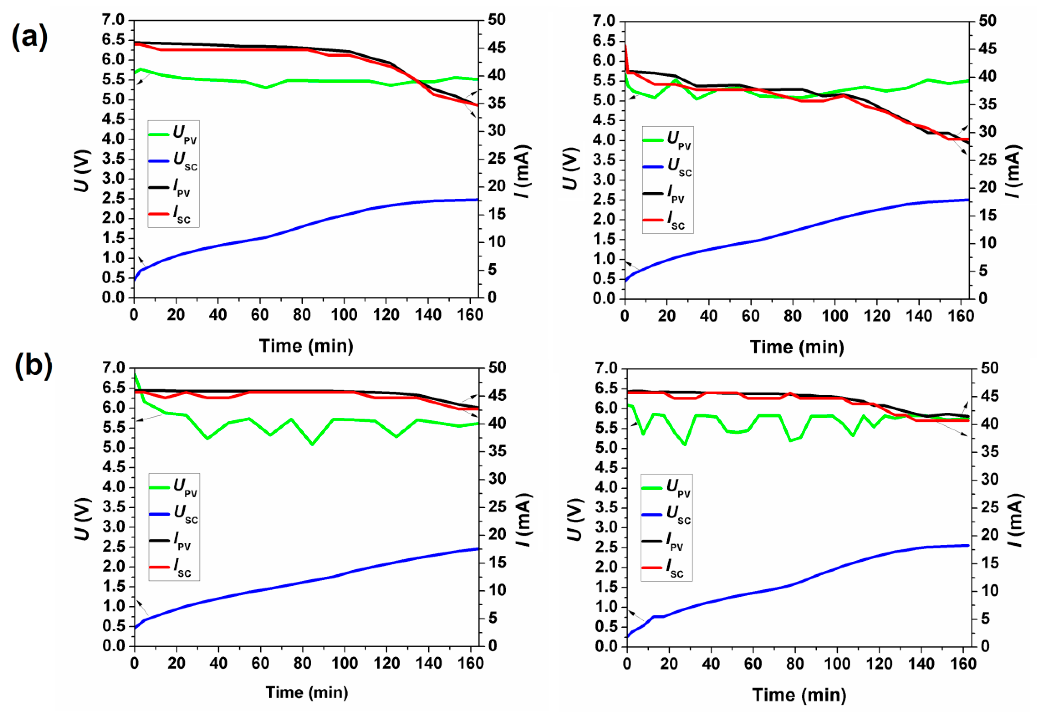
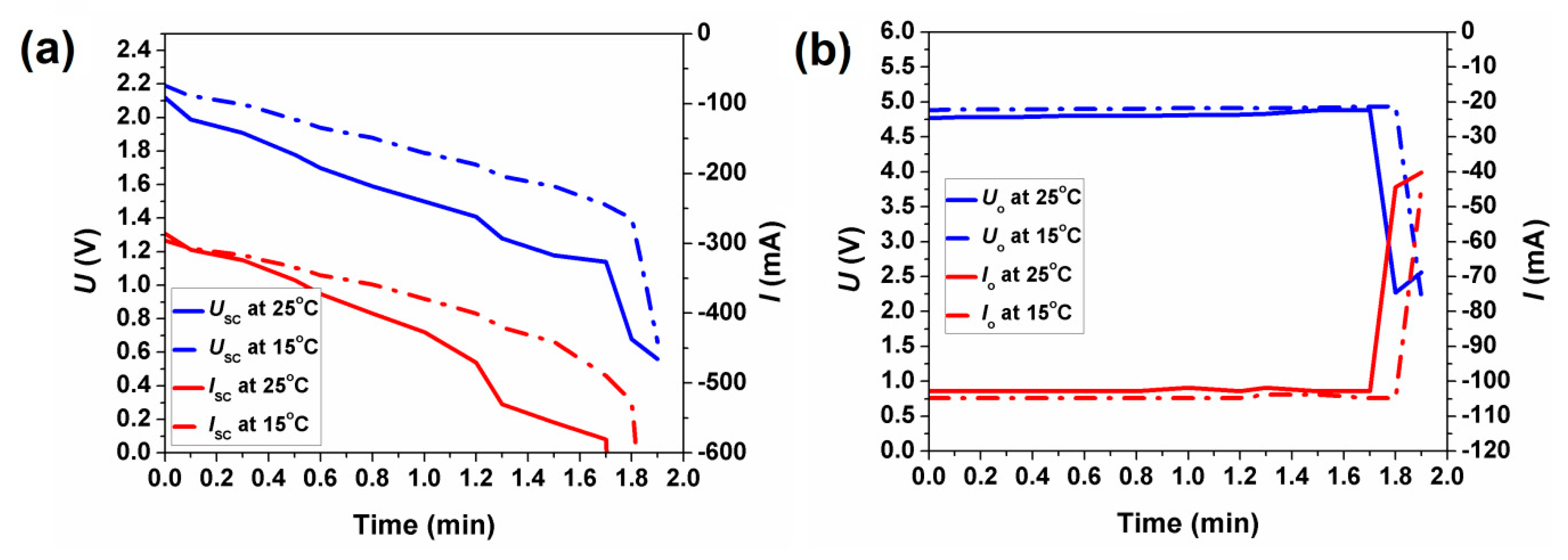
3.3. Integrated Silicon Solar Cell–Supercapacitor Photo-Rechargeable Device-Charging Efficiency Optimisation

It was intended that the total dimensions of the integrated solar cell-REHES-type supercapacitor charger models, did not exceed 150 mm × 150 mm. The final performance was evaluated on the basis of diagnostic tests conducted at fixed temperature of 15 and 25 °C and under the light radiation of 600 and 1000 W m−2. The schematic diagram of the electronic system used in the charger model is shown in Figure S1. The current source, voltage control system and supercapacitor charging block were placed on a printed circuit board (PCB) which is shown from the side of the elements in Figure S6a (top layer), and from the print side (bottom layer), i.e., where the silicon photovoltaic cells are placed, Figure S6b.
When designing a housing of the charger model, it was decided to use a part of the supercapacitor case (the top surface) as the charger housing where a PCB with the electronic control system and a solar panel were placed. In order to reduce the mutual influence of the supercapacitor elements induced by slight variabilities in capacitance/resistance of the individual coin cells, it was decided to introduce changes to the electrical connection system by adding a diode separator (Figure S7), through which the supercapacitors are connected to the charger system. The diode separator consisted of six Schottky diodes in a push–pull connection. The system was characterised with a good separation of the individual supercapacitor banks at a low forward voltage (approx. 200 mV), which was not without significance in our system as the supercapacitor can be charged up to 3 V. After such modernisation, the photovoltaic panel was mounted in a masking frame printed on a 3D printer using an ecological friendly material-poly(lactic acid) (PLA), as presented in Figure S8. Other elements such as: the operating mode switch (allowing switching between charge and discharge mode), LED charging indicators, the measurement socket (enabling connection to the microprocessor measurement system) and the energy receiving socket (for external load connection) were placed directly on the printed circuit board.
Figure S9 shows a block diagram of the electronic system used for measuring the charging, discharging and recharging characteristics of a supercapacitor charger model. The charger was connected through the measurement socket to a microprocessor-based meter enabling the measurement of current-voltage characteristics under different operation modes as well as to monitor the simulated environmental conditions and intensity of the light during the diagnostic tests. The data were gathered and saved on a PC hard drive using specially designed computer software. A 100 W LED lamp with a light colour temperature of 6000 K and illumination intensity control system was used as a source of solar radiation. A view of a complete laboratory measurement station is depicted in Figure S10.
The PV modules used in the study consisted of ten series connected and two parallel connected silicon cells with dimensions of 50 mm × 20 mm and 50 mm × 50 mm, respectively. The current–voltage characteristics of the modules and their main electrical parameters are shown in Figure S2 and Table S2. As seen, they both exhibit good photoelectrochemical characteristics suitable for the construction of energy storage systems based on supercapacitors.
At first, the solar charger based on REHES-type supercapacitors and ten silicon photovoltaic cells with size 50 mm × 20 mm connected in series (see Figure 4a) were investigated. From the characteristics shown in Figure S11, presenting the charging process of integrated supercapacitor-solar cell charger, it can be seen that the initial, relatively high, charging current of ca. 120 mA decreases very quickly reaching 16 mA within 2.5 h of charging for the final voltage on supercapacitor of approx. 1.95 V. The initial voltage difference for the charging current ISC = 120 mA between UPV = 3.54 V and USC = 0.39 V was equal to ∆U = 3.15 V, where UPV, USC are voltage across the PV panel and supercapacitor, respectively. However, at the end of charging, the voltage difference between UPV = 3.97 V and Ucl = 1.95 V was already ∆U = 2.02 V for the charging current Icl = 16 mA. Based on the obtained results, it has been concluded that the model works inefficiently with the developed electronic system of a supercapacitor charger. Hence, in conclusion, in order to maintain a constant supercapacitor charging current over the whole charging period, the voltage difference between the output voltage from the PV panel and the increasing supercapacitor voltage must be greater than 3 V throughout the whole charging cycle. This requirement will be met by a PV panel with an operating voltage of Umax = 5.5 V. Therefore, a new electronic system of a supercapacitor charger was designed, where the silicon PV panel was fabricated from the cells with the following parameters: open circuit current Uoc = 6.5 V and short circuit current Isc = 164.5 mA (Table S2).
In the next step, the new charger model based on REHES-type supercapacitors and two silicon photovoltaic cells with size 70 mm × 50 mm was investigated (see Figure 4), additionally selecting two different temperatures and illumination conditions, namely T = 15 or 25 °C and E = 600 or 1000 W m−2. Figure 5 and Figure 6 show the environmental conditions during charging as well as the current–voltage characteristics of both charger components, i.e., a PV module and a supercapacitor, respectively.
After charging the supercapacitor to USC = 2.4 V the operating mode in the program collecting data was switched to discharge, and the supercapacitor discharge current and voltage as well as load current and voltage on the resistor Ro = 47 Ω were measured (Figure 7, Figure S12). Due to connection of the external load during the supercapacitor discharge process, the value of potential showed approx. 0.5 V as the end value (Figure S12, left side). Disconnecting the external load, the actual voltage value registered on supercapacitor showed 1 V, therefore the real stage of supercapacitor discharge was assumed to be 1 V.
Hence, after discharging to USC = 1 V, the operating mode was switched to charging again, and the current and voltage of the supercapacitor during recharging to USC = 2.4 V were measured at 25 and 15 °C (Figures S13 and S14). The comparison of the charge, discharge and reacharge profiles for the solar charger at the temperature of 15 and 25 °C and the irradiation of 600 and 1000 W m−2 is shown in Figure S15. The selected electrical parameters of investigated energy storage system at various laboratory conditions are also summarised in Table 2 and Table 3. Table 2 shows that the first supercapacitor charging time up to the voltage of 2.4 V is comparable regardless of the light intensity and operating temperature, and ranges from ca. 130 to 160 min. The recharging time between 1.0 and 2.4 V is typically shorter and does not exceed 2 h.
The analysis of the data collected in Table 3 shows that the efficiency of the supercapacitor-charging system during the first charging is about 28–30%, regardless of the light intensity. At a lower operating temperature, T = 15 °C, the efficiency is less than 2% higher than at 25 °C. During cyclic operation (discharge-recharge), the efficiency increases to 72% at the temperature of 25 °C and 77% at the temperature of 15 °C. This gives a 5% increase in efficiency in favor of a lower temperature. Low efficiency in the range of 72 ÷ 77% was caused by the reduced voltage threshold to which the supercapacitor was charged, i.e., USC = 2.4 V and the high voltage to which the supercapacitor USCR = 0.9 V was discharged, which gives the difference in the effective voltage of the supercapacitor equal to Ursc = 1.5 V. This difference is half the value of the rated operation voltage of the supercapacitor (Ur = 3 V). Finally, we can conclude that the constructed new supercapacitor charger showed slightly better parameters during charging at T = 15 °C. The use of the converter increasing the voltage to 5 V does not affect the efficiency of the entire system, namely ŋrp = 73% for the temperature of 25 °C and ŋrp = 77% for the temperature of 15 °C, regardless of the illumination. However, the converter improves the working conditions for the receiver (constant voltage at the output with constant load current) (see Figure 7).

4. Conclusions

Redox electrolyte hybrid energy storage (REHES) concept has been, for the first time, considered for the construction of a coupled supercapacitor–silicon photovoltaic cell photo-rechargeable device (solar charger) for uninterrupted solar energy conversion and storage within a single portable device. REHES system comprised of the iodide-based electrolyte and has been optimised in order to achieve the highest output capacitance/energy and high charge–discharge dynamics. Supercapacitor module, that has been built using parallel and series connections between CR2032 coin cells, was characterised with the rated capacitance and voltage of 60 F and 3 V, respectively.
Based on the developed engineering concept and obtained results we can conclude that the proposed charger model has a charging time of ca. 2 h for the first charging and recharging of the supercapacitor bank, using the illumination intensity from 600 to 1000 W m−2 at ambient temperature. Temperature changes from 15 °C to 25 °C, do not significantly affect the charging times of the device, which guarantees a reliable performance at European latitudes on a cloudless day in the 2nd and 3rd quarter of the year from 8:00 to 16:00.

Supplementary Materials

The following are available online at https://www.mdpi.com/article/10.3390/en14092708/s1. Figure S1: Schematic diagrams of a supercapacitor charger circuit with (a) ten silicon photovoltaic cells connected in series and (b) two silicon photovoltaic cells connected in parallel. Figure S2: IV characteristics of: (a) ten silicon photovoltaic cells with size 50 mm × 20 mm connected in series and (b) two silicon photovoltaic cells with size 70 mm × 50 mm in series (left) and in parallel (right) connection. Figure S3: (a) N2 (77 K) adsorption/desorption isotherms and (b) pore size distribution, (c) cumulative pore volume and (d) cumulative surface area of ACs. Figure S4: GCPL characteristics of the AC-3 (a) and the AC-2 (b) REHES-type cells (including the characteristics of the individual electrodes recorded vs. the reference electrode) and schematic representation of the operation mechanism in the absence, i.e., such as in Figure S3a (c) and in the presence, i.e., such as in Figure S3b (d) of the parasitic redox-shuttle contribution at the negative electrode. Figure S5: Cell capacitance as a function of (a) electrode density and (b) volume of the free space in the AC electrode. Figure S6: PCB view from (a) the elements side, (b) from the print side and (c) 3D image of electronic circuit board (generated from Altium design program). Figure S7: Schematic diagram of the diode separator. Figure S8: View from the electronics mounting side of the PCB model mounted in a PLA frame, Figure S9: Block diagram of the electronic system for measuring of the charging, discharging and recharging characteristics of a solar charger based on supercapacitors and silicon PV cells. Figure S10: View of the microprocessor system for measuring the charging, discharging and recharging characteristics of a charger model based on supercapacitors and silicon PV cells. Figure S11: (a) Environmental conditions during charging of a supercapacitor charger model built from ten silicon photovoltaic cells connected in series, (b) charging characteristics of a supercapacitor charger model and (c) view of the microprocessor measurement system used in the study. Figure S12: Discharging characteristics of a supercapacitor charger model (left side) and load voltage and current on the resistor Ro = 47 Ω (right side) at 25 °C (a) and 15 °C (b), where Uo—voltage across the resistor Ro, Ip—current on the resistor Ro. Figure S13: Experimental conditions for recharging process (a) and the boost chart (b) of a supercapacitor charger model at 25 °C and the illuminance of 1000 W m−2 (left side) and 600 W m−2 (right side). Figure S14: Experimental conditions for recharging process (a) and the boost chart (b) of a supercapacitor charger model at 15 °C and the illuminance of 1000 W m−2 (left side) and 600 W m−2 (right side). Figure S15: Charging (a), discharging (b) recharging (c) characteristics of a supercapacitor charger model using two 50 × 70 mm silicon solar cells under different simulated environmental conditions.

Author Contributions

Conceptualization, M.S.-N. and I.P.; data curation, P.R.; formal analysis, P.R., S.D., I.P. and A.I.; investigation, P.R., J.L., A.A.M., S.D. and I.P.; methodology, M.S.-N. and I.P.; supervision, P.J.K.; visualization, K.A.B.; writing—original draft, M.S.-N. and A.I.; writing—review and editing, M.S.-N., K.A.B. and A.I. All authors have read and agreed to the published version of the manuscript.

Funding

This research was funded by the Polish National Centre for Research and Development grant number TECHMATSTRATEG1/347431/14/NCBR/2018.

Institutional Review Board Statement

Not applicable.

Informed Consent Statement

Not applicable.

Data Availability Statement

Not applicable.

Acknowledgments

The authors are grateful for financial support from the Polish National Centre of Research and Development (TECHMATSTRATEG1/347431/14/NCBR/2018). The authors thank Piotr Otreba for printing the device housing using the 3D printer.

Conflicts of Interest

The authors declare no conflict of interest.

References

  1. Schmidt, D.; Hager, M.D.; Schubert, U.S. Photo-rechargeable electric energy storage systems. Adv. Energy Mater. 2016, 6, 1500369. [Google Scholar] [CrossRef]
  2. Chauhan, A.; Saini, R.P. A review on integrated renewable energy system based power generation for stand-alone applications: Configurations, storage options, sizing methodologies and control. Renew. Sustain. Energy Rev. 2014, 38, 99–120. [Google Scholar] [CrossRef]
  3. Afzal, M.M.; Khan, M.A.; Hassan, M.A.S.; Wadood, A.; Uddin, W.; Hussain, S.; Rhee, S.B. A comparative study of supercapacitor-based STATCOM in a grid-connected photovoltaic system for regulating power quality issues. Sustainability 2020, 12, 6781. [Google Scholar] [CrossRef]
  4. Logerais, P.-O.; Riou, O.; Camara, M.A.; Durastanti, J.-F. Study of photovoltaic energy storage by supercapacitors through both experimental and modelling approaches. J. Sol. Energy 2013, 659014. [Google Scholar] [CrossRef] [Green Version]
  5. Beaudin, M.; Zareipourn, H.; Schellenberg, A.; Rosehart, W. Energy storage for mitigating the variability of renewable electricity sources, energy storage for smart grids. In Planning and Operation for Renewable and Variable Energy Resources (VERs); Academic Press: New York, NY, USA, 2015; pp. 1–33. [Google Scholar]
  6. Conway, B.E. Electrochemical Supercapacitors: Scientific Fundamentals and Technological Applications; Springer: New York, NY, USA, 1999. [Google Scholar]
  7. Zhang, L.; Zhao, X.S. Carbon-based materials as supercapacitor electrodes. Chem. Soc. Rev. 2009, 38, 2520–2531. [Google Scholar] [CrossRef]
  8. Akinwolemiwa, B.; Chuang, P.; Chen, G.Z. Redox electrolytes in supercapacitors. J. Electrochem. Soc. 2015, 162, A5054–A5059. [Google Scholar] [CrossRef]
  9. Zhang, L.; Yang, S.; Chang, J.; Zhao, D.; Wang, J.; Yang, C.; Cao, B. A review of redox electrolytes for supercapacitors. Front. Chem. 2020, 8, 413. [Google Scholar] [CrossRef] [PubMed]
  10. Lee, J.; Srimuk, P.; Fleischmann, S.; Su, X.; Hatton, A.; Presser, V. Redox-electrolytes for non-flow electrochemical energy storage: A critical review and best practice. Prog. Mater. Sci. 2019, 101, 46–89. [Google Scholar] [CrossRef]
  11. Lota, G.; Frackowiak, E. Striking capacitance of carbon/iodide interface. Electrochem. Commun. 2009, 11, 87–90. [Google Scholar] [CrossRef]
  12. Roldan, S.; Granda, M.; Menendez, R.; Santamaria, R.; Blanco, C. Mechanisms of energy storage in carbon-based supercapacitors modified with a quinoid redox-active electrolyte. J. Phys. Chem. C 2011, 115, 17606–17611. [Google Scholar] [CrossRef]
  13. Skunik-Nuckowska, M.; Węgrzyn, K.; Dyjak, S.; Wisińska, N.H.; Kulesza, P.J. Polyoxometalate/hydroquinone dual redox electrolyte for hybrid energy storage systems. Energy Stor. Mater. 2019, 21, 427–438. [Google Scholar] [CrossRef]
  14. Dsoke, S.; Abbas, Q. Benefits of organo-aqueous binary solvents for redox supercapacitors based on polyoxometalates. ChemElectroChem. 2020, 7, 2466–2476. [Google Scholar] [CrossRef]
  15. Górska, B.; Bujewska, P.; Fic, K. Thiocyanates as attractive redox-active electrolytes for high-energy and environmentally-friendly electrochemical capacitors. Phys. Chem. Chem. Phys. 2017, 19, 7923–7935. [Google Scholar] [CrossRef]
  16. Lee, J.; Choudhury, S.; Weingarth, D.; Kim, D.; Presser, V. High performance hybrid energy storage with potassium ferricyanide redox electrolyte. ACS Appl. Mater. Interfaces. 2016, 8, 23676–23687. [Google Scholar] [CrossRef] [PubMed]
  17. Fic, K.; Frackowiak, E.; Béguin, F. Unusual energy enhancement in carbon-based electrochemical capacitors. J. Mater. Chem. 2012, 22, 24213–24223. [Google Scholar] [CrossRef]
  18. Frackowiak, E.; Meller, M.; Menzel, J.; Gastol, D.; Fic, K. Redox-active electrolyte for supercapacitor application. Faraday Discuss. 2014, 172, 179–198. [Google Scholar] [CrossRef] [PubMed]
  19. Abbas, Q.; Babuchowska, P.; Frackowiak, E.; Béguin, F. Sustainable AC/AC hybrid electrochemical capacitors in aqueous electrolyte approaching the performance of organic systems. J. Power Source 2016, 326, 652–659. [Google Scholar] [CrossRef]
  20. Platek, A.; Piwek, J.; Fic, K.; Frackowiak, E. Ageing mechanisms in electrochemical capacitors with aqueous redox-active electrolytes Electrochim. Acta 2019, 311, 211–220. [Google Scholar] [CrossRef]
  21. Fadakar, Z.; Nasirizadeh, N.; Bidoki, S.M.; Shekari, Z.; Mottaghitalab, V. Fabrication of a supercapacitor with a PVA–KOH–KI electrolyte and nanosilver flexible electrodes. Microelectron. Eng. 2015, 140, 29–32. [Google Scholar] [CrossRef]
  22. Wang, X.; Chandrabose, R.S.; Chun, S.-E.; Zhang, T.; Evanko, B.; Jian, Z.; Boettcher, Z.W.; Stucky, G.D.; Ji, X. High energy density aqueous electrochemical capacitors with a KI-KOH electrolyte. ACS Appl. Mater. Interfaces 2015, 7, 19978–19985. [Google Scholar] [CrossRef]
  23. Abbas, Q.; Fitzek, H.; Pavlenko, V.; Gollas, B. Towards an optimized hybrid electrochemical capacitor in iodide based aqueous redox-electrolyte: Shift of equilibrium potential by electrodes mass-balancing. Electrochim. Acta 2020, 337, 135785. [Google Scholar] [CrossRef]
  24. Prehal, C.; Fitzek, H.; Kothleitner, G.; Presser, V.; Gollas, B.; Freunberger, S.A.; Abbas, Q. Persistent and reversible solid iodine electrodeposition in nanoporous carbons. Nat. Commun. 2020, 11, 4838. [Google Scholar] [CrossRef]
  25. Plebankiewicz, I.; Bogdanowicz, K.A.; Iwan, A. Photo-rechargeable electric energy storage systems based on silicon solar cells and supercapacitor-engineering concept. Energy 2020, 13, 3867. [Google Scholar] [CrossRef]
  26. Wisińska, N.H.; Skunik-Nuckowska, M.; Dyjak, S.; Kulesza, P.J. Factors affecting performance of electrochemical capacitors operating in Keggin-type silicotungstic acid electrolyte. Appl. Surf. Sci. 2020, 530, 147273. [Google Scholar] [CrossRef]
  27. Laheäär, A.; Przygocki, P.; Abbas, Q.; Beguin, F. Appropriate methods for evaluating the efficiency and capacitive behavior of different types of supercapacitors. Electrochem. Commun. 2015, 60, 21–25. [Google Scholar] [CrossRef]
  28. Lee, J.; Srimuk, P.; Fleischmann, S.; Ridder, A.; Zeiger, M.; Presser, V. Nanoconfinement of redox reactions enables rapid zinc iodide energy storage with high efficiency. J. Mater. Chem. A. 2017, 5, 12520–12527. [Google Scholar] [CrossRef]
  29. Akinwolemiwa, B.; Wei, C.; Yang, Q.; Yu, L.; Xia, L.; Hu, D.; Peng, C.; Chen, G.Z. Optimal utilization of combined double layer and nernstian charging of activated carbon electrodes in aqueous halide supercapattery through capacitance unequalization. J. Electrochem. Soc. 2018, 165, A4067–A4076. [Google Scholar] [CrossRef]
  30. Chen, L.; Bai, H.; Huang, Z.; Li, L. Mechanism investigation and suppression of self-discharge in active electrolyte enhanced supercapacitors. Energy Environ. Sci. 2014, 7, 1750–1759. [Google Scholar] [CrossRef] [Green Version]
  31. Przygocki, P.; Abbas, Q.; Bèguin, F. Capacitance enhancement of hybrid electrochemical capacitor with asymmetric carbon electrodes configuration in neutral aqueous electrolyte. Electrochim. Acta 2018, 269, 640–648. [Google Scholar] [CrossRef]
  32. Gogotsi, Y.; Simon, P. True performance metrics in electrochemical energy storage. Science 2011, 18, 917–918. [Google Scholar] [CrossRef] [PubMed] [Green Version]
Figure 1. (a) Cyclic voltammetry profiles (0.005 V s−1) of KI-REHES Swagelok®-type cells fabricated from different ACs electrodes. (b) Cyclic voltammetry characteristics (at 0.005 V s−1) recorded in the three-electrode cell for the ACs electrodes in the presence of KI electrolyte. (c) Capacitance changes as a function of discharge current and (d) self-discharge profiles for different ACs-based REHES systems.
Energies 14 02708 g001
Figure 2. (a) AC-6/KI-CR2032 coin cell and its components, (b) coin cell tested: as a power supply for electronic watch, (c) Ragone chart derived from the constant power test, (d) capacitance response during 10,000 of GCPL cycles at 1 A g−1.
Energies 14 02708 g002
Figure 3. Inside (a) and outside (b) view on 60 F supercapacitor module, (c) cyclic voltammetry (at 0.03 V s−1) and (d) GCPL (at 0.85 A) characteristics of a module.
Energies 14 02708 g003
Figure 4. Photographs of constructed devices based on silicon solar cells and supercapacitors: (a) ten silicon photovoltaic cells with size 50 mm × 20 mm connected in series and (b) two silicon photovoltaic cells with size 70 mm × 50 mm connected in parallel.
Energies 14 02708 g004
Figure 5. Environmental conditions during charging of a supercapacitor charger model using two 70 mm × 50 mm PV cells connected in parallel at a temperature of 25 °C (a) and 15 °C (b) under solar irradiance of 1000 W m−2 and 600 W m−2 (right side).
Energies 14 02708 g005
Figure 6. Charging characteristics of a supercapacitor charger model at 25 °C (a) and 15 °C (b) and illuminance of 1000 W m−2 (left side) and 600 W m−2 (right side), where UPV—voltage on the PV panel, IPV—current on the PV panel, USC—supercapacitor voltage, ISC—supercapacitor current.
Energies 14 02708 g006
Figure 7. Supercapacitor discharge characteristics (a), and dependence of voltage and current on the resistor Ro = 47 Ω during supercapacitor discharge (b).
Energies 14 02708 g007
Table 1. Performance metrics of Swagelok® laboratory cells.
ParameterAC-1AC-2AC-3AC-4AC-5AC-6
Q (mAh g−1)15.324.720.522.130.425.4
C (F g−1)355244 496555
C* (F g−1)15.819.017.817.718.315.5
E (Wh kg−1)10.816.113.815.220.317.0
E* (Wh kg−1)4.95.95.65.65.74.8
C/C0 (%)20.616.021.640.642.145.8
U/U0 (%)48.79.357.346.732.749.3
d (g cm−3)0.680.540.610.530.400.42
Q—gravimetric capacity, Q, C, E—gravimetric capacity, capacitance and energy at 0.1 A g−1 normalised against dry mass of both electrodes. ‘*’ index stands for the gravimetric parameters at 0.1 A g−1 normalised per total mass of the device, d—the average density of the electrodes.
Table 2. Selected electrical parameters of investigated energy storage system under different laboratory conditions.
Parameters25 °C15 °C
1000 W/m2600 W/m21000 W/m2600 W/m2
Supercapacitor charging time
(up to USC = 2.4 V) (min)
132.7134.1164.5132.5
Supercapacitor recharging time
(up to USC = 2.4 V) (min)
68.091.251.1114.3
Supercapacitor discharging time
(up to USC = 0.9 V) (min)
1.81.9
Time of constant voltage under load of Ro = 47 Ω (Uo > 4.8 V) (min)1.81.9
Table 3. Summary of selected electrical parameters of investigated energy storage system at various laboratory conditions.
Parameters25 °C15 °C
1000 W/m2600 W/m21000 W/m2600 W/m2
Working voltage of supercapacitor bank, USC (V)2.42.42.42.4
Rated capacity of supercapacitor bank, CSC (F)60606060
Theoretical amount of storage energy, W (Ws)172.8172.8172.8172.8
Time of first charging, tn (min)132.7134.1164.5132.5
Efficiency of the system during first charging up to USC = 2.4 V, ŋn (%)28.328.329.929.9
Recovered energy, Wd (Ws)48.848.851.751.7
Voltage on supercapacitor bank after connecting load of Rwej = 4.7 Ω during discharge tr, USC (V)2.12.12.22.2
Discharge time up to USC = 0.9 V, tr (min)1.71.71.81.8
Energy supplied to supercapacitor bank during recharging up to USC = 2.4 V, Edc (Ws)67.567.567.567.5
Recharging time up to USC = 2.4 V, td (min)68.091.251.1114.3
System efficiency during recharging, ŋd (%)72727777
Potential on converter’s bias after connecting the load of Robc = 4.7 Ω in time tr, Uobc > (V)4.84.84.84.8
Energy supplied to a load during discharge up to Uo = 4.8 V, Ero (Ws)48.948.951.851.8
Efficiency of the system after using converter, ŋrp (%)73737777
Publisher’s Note: MDPI stays neutral with regard to jurisdictional claims in published maps and institutional affiliations.

