Article

Simulation and Techno-Economic Analysis of a Power-to-Hydrogen Process for Oxyfuel Glass Melting

1
Research Center on Energy Transmission and Storage (FENES), Faculty of Electrical and Information Technology, University of Applied Sciences (OTH) Regensburg, Seybothstrasse 2, D-93053 Regensburg, Germany
2
Chair of Regenerative Energy Systems (RES), Campus Straubing for Biotechnology and Sustainability, Technical University Munich, Schulgasse 16, D-94315 Straubing, Germany
3
Laboratory of Sorption Processes (LSP), Faculty of Mechanical Engineering, Technical University of Applied Sciences (OTH) Regensburg, Galgenbergstraße 30, D-93053 Regensburg, Germany
4
Faculty of Electric and Information Technology, Technical University of Applied Sciences (OTH) Regensburg, Seybothstrasse 2, D-93053 Regensburg, Germany
*
Author to whom correspondence should be addressed.
Energies 2021, 14(24), 8603; https://doi.org/10.3390/en14248603
Submission received: 12 November 2021 / Revised: 7 December 2021 / Accepted: 16 December 2021 / Published: 20 December 2021

Abstract

:
As an energy-intensive industry sector, the glass industry is strongly affected by the increasingly stringent climate protection targets. As established combustion-based production systems ensure high process stability and glass quality, an immediate switch to low greenhouse gas emission processes is difficult. To approach these challenges, this work investigates a step-by-step integration of a Power-to-Hydrogen concept into established oxyfuel glass melting processes using a simulation approach. This is complemented by a case study for economic analysis on a selected German glass industry site by simulating the power production of a nearby renewable energy park and subsequent optimization of the power-to-hydrogen plant performance and capacities. The results of this study indicate, that the proposed system can reduce specific carbon dioxide emissions by up to 60%, while increasing specific energy demand by a maximum of 25%. Investigations of the impact of altered combustion and furnace properties like adiabatic flame temperature (+25 °C), temperature efficiency ( Δ ξ = −0.003) and heat capacity flow ratio ( Δ z H L = −0.009) as a function of H2 content in the fuel mixture and resulting furnace efficiencyindicate that pure hydrogen-oxygen combustion has less impact on melting properties than assumed so far. Within the case study, high CO2 abatement costs of 295 €/t CO2-eq. were determined. This is mainly due to the insufficient performance of renewable energy sources. The correlations between process scaling and economic parameters presented in this study show promising potential for further economic optimization of the proposed energy system in the future.

1. Introduction

Climate change is an urgent global challenge that affects human living conditions through weather extremes, droughts, and floods. To prevent the increasing risks of climate change, a rapid and significant reduction in anthropogenic carbon dioxide (CO2) emissions is crucial. These CO2 emissions are mainly responsible for climate change, and are primarily caused by leading industrial nations. Therefore, steps towards a significant reduction of CO2 emissions in energy generation, the building sector, and transport have been continuously discussed and established in highly industrialized nations. However, energy-intensive industries such as steel, paper, and chemicals production are also of increasing interest in these considerations. Although often neglected at present, the glass industry is one of these energy-intensive industries. This work focuses particularly on the German glass industry, which accounts for 20% of European glass production. In Germany, about 56,000 people are employed within 390 companies, generating a total revenue of 9.8 billion € per year. Since most of the products are intended for European and global export, the German glass industry is of considerable economic and social importance [1].
The German glass industry is facing increasing financial and social pressure to reduce CO2 emissions and energy consumption. The main reason for its high energy consumption is the melting process, accounting for 50–80% of the total energy input (in 2015: approx. 18.53 TWh) [2,3,4]. In addition, more than 75% of the glass industry’s total energy consumption is covered by so far low-cost natural gas, which in turn has a negative impact on CO 2 emissions. Further energy sources electricity (approx. 17%) and mineral oil (approx. 7%). Over the years, extensive know-how has been accumulated on fossil fuel-based melting processes, which in turn guarantees consistently high glass quality. If the German glass industry is to remain economically competitive, access to a cost-effective energy supply for glass manufacturers must be ensured in the future, also with a view to future climate protection regulations. A major challenge in this context is the transition of the energy supply to an environmentally friendly, low-CO2 emission system.

1.1. CO2 Emissions of the German Glass Industry

The CO2 emissions caused by the German glass industry have stagnated at a relatively constant level of ≈4 million t CO2-eq. per year since 2005 [5]. The industry sector is listed as exposed to carbon leakage and has therefore received free allocated emission allowances. As a result, the established European Union emission trading system (EU-ETS) has not been able to implement any financial incentives to reduce CO2 emissions. However, since the beginning of the third trading period of the EU-ETS (2013) and the associated reduction in the amount of free allocated emission allowances, the actual CO2 emissions of the German glass industry have exceeded the amount of these free allowances [5]. An expected further reduction in the amount of free allocated emission allowances in the fourth trading period of the EU-ETS, and the associated price dynamics in the European Energy Exchange (EEX) trading system, will exert significant financial pressure on the glass industry to reduce CO2 emissions in the future. This pressure is further intensified by the introduction of taxation for CO2 emissions, currently being at about 30–40 €/t CO2-eq. with a subsequent fast linear increase up to 180 €/t CO2-eq. by 2045 [6].

1.2. Structure and Scope of This Work

In recent years, various research approaches have been pursued to develop energy concepts for reducing CO2 emissions while simultaneously integrating fluctuating renewable energy sources into the glass industry. So far no comprehensive overview of the current state of the art in glass production is available in the literature. Therefore, a brief overview of the current state of the art of glass production is provided and current approaches for reducing CO2 emissions are discussed. Since these approaches have drawbacks for large-scale application, a new, innovative approach to integrating a power-to-hydrogen (PtH2) concept into glass melting processes is described. This concept enables a step-wise conversion of combustion processes to hydrogen-based melting processes, which could overcome the limitations of current approaches in terms of CO2 reduction and integration of renewable energy sources in the glass industry. The main focus of this study is the numerical evaluation of this concept, which is depicted and evaluated by means of simulations based on mass and energy balances. The predictions of these models enable a subsequent energy efficiency analysis as well as the evaluation of positive effects on CO2 emission reduction of the integration of PtH2 into oxyfuel-based glass melting processes. In a final step, the presented models are incooperated within a case study for the integration of PtH2 into the German container glass industry, thus enabling an initial techno-economic analysis.

2. Literature Review

CO2 emissions during glass melting are depending on the specific energy demand as well as the efficiency of the furnace. Therefore, these two parameters will be briefly addressed, before various established and innovative melting tank designs are described. Some of these more advanced processes also focus on reducing CO2 emissions.

2.1. Specific Energy Demand

The specific energy demand is highly dependent on the glass type being produced, its batch and glass composition, the melting technology, and the furnace capacity. Improvements in energy efficiency and material utilization enabled the reduction of the specific energy demand from 4000 kWh/t glass in the 1930s to under 1000 kWh/t glass in 2016 (see Figure 1). Associated with this, the specific CO2 emissions per ton of molten glass have been reduced from approximately 1300 kg CO2-eq./t glass in the 1930s to an average value of 250 kg CO2-eq./t glass in 2016.

2.2. Furnace Efficiency

The furnace efficiency of a melting tank is defined as the ratio of the input energy (e.g., fuel, electrical power) to the energy transferred into the molten glass (see Equation (7)). Further, furnace efficiency of a melting system is a function of its pull rate (Figure 2). The pull rate indicates the sizing factor of a melting system and determines how much glass can be produced within a day of operation. An increasing pull rate yields an improved area-to-volume ratio and thus, reduced heat losses.
So far, reducing energy costs has been the main motivation for the glass industry to enhance both material and energy utilization efficiencies. In terms of enhanced material utilization, the addition of cullets to the glass batch has been the most important step in recent decades. The addition of only 10% of cullets to the batch composition already reduces the average energy consumption of the melting process by 2–3% [8,9]. The addition of cullets further reduces the required amount of carbonates in the batch. As the decomposition reactions of carbonates cause CO2 emissions, the addition of cullets also causes a reduction of CO2 emissions. However, cullets from production residues are used in most cases. The extensive use of waste glass cullets is limited, due to its impurities, various glass colors and expensive logistic costs [9].

2.3. Melting Tank Design

The design of a melting tank is decisive in terms of energy consumption and related CO2 emissions. The most common tank designs are (i) regenerative, (ii) recuperative, (iii) oxyfuel and (iv) all electric melting. A comparison of key values for this established designs is shown in Table 1.
Regenerative furnaces can be considered as the current standard technology for glass melting and are established in all industry sectors. This concept was invented by Friedrich and Hans Siemens in 1862 [11]. Because of their long use, regenerative furnaces have recently achieved only modest improvements in energy efficiency [12].
Within recuperative melting tanks, combustion air is preheated by indirect contact with the exhaust gas through a dual shell or shell-and-tube heat exchangers. Thus, the efficiency of heat transfer between exhaust gas and ambient is lower, while a cleaner furnace atmosphere is possible [13]. Besides regenerative or recuperative preheating of combustion air, the preheating of cullets and/or batch raw materials is established. Therefore, indirect heat exchanger systems are primarily used, as direct contact between batch and exhaust gas can cause contamination of raw materials [14].
An alternative approach is oxyfuel melting. Within oxyfuel-fired melting, natural gas is combusted in an atmosphere of nearly pure oxygen (O2), rather than ambient air. This results in increased furnace efficiency, due to much higher adiabatic flame temperatures (2775 °C vs. 2440 °C for common air-gas) and increased heat capacity flow [15]. Thus, the efficiency of oxyfuel furnaces is increased by about 5–10% compared to a similar regenerative furnace, and about 25–40% compared to a similar recuperative furnace, respectively [13]. Moreover, the associated reduction of nitrogen (N2) fractions in the furnace atmosphere enable a significant reduction of the nitrogen oxide (NOx) emissions of oxyfuel melting furnaces making them more attractive concerning stricter environmental regulations [16]. The application of oxyfuel furnaces is carefully considered in each case (high costs for O2-infrastructure, high-quality ceramics for brick-work, etc.) and is often omitted due to insufficient returns on investment. Currently, oxyfuel melting is widely used in the special glass industry, where glass compositions are more energy-intensive [17]. The full potential of oxyfuel furnaces has not been fully exploited yet, as they have largely been constructed as simplified regenerative furnaces, without further special adaptation of the furnace geometry [18].
A further improvement in terms of efficiency of the oxyfuel melting process can be achieved by thermochemical reformation (TCR) of natural gas (e.g., Optimelt process by Praxair). This enhances both the recovery efficiency by means of natural gas reformation to carbon monoxide (CO) and Hydrogen (H2) and the inferior calorific value of the fuel gas mixture from approx. 10 kWh/m3 to 12.6 kWh/m3 [19].
As a combination of regenerative and oxyfuel concepts, the so-called HeatOx process has recently been applied on an industrial scale. It involves preheating of O2 and natural gas for oxyfuel combustion. This enables an additional increase in the efficiency of the furnace, and a further reduction in pollutant emissions [20].
All-electric melting has several advantages over combustion-based melting, such as higher overall efficiency (see Figure 2), higher specific melting capacity (t/m2), and lower emissions of dust and toxic gases [21]. Despite these promising properties, all-electric melting is currently only used in small-scale applications of glass production (up to 50 t/d). Whether an extension and upscaling of this technology without extensive changes in the production processes is possible is still the subject of controversial debate [22]. Nevertheless, there have been successful pilot plants of up to 240 t/d recently. However, these plants require very complex technical solutions such as rotating melting areas, an extensive heat control strategy and careful positioning of electrodes [7]. In addition, currently established all-electric melting systems do not allow flexible integration of electricity from renewable energies. A strictly constant input of heat is crucial for a stable batch-to-melt conversion without excessive bubbling and therefore a constant pull rate of glass [13].
The advantages of electric melting are also used in combustion-based melting processes. Therefore, electrodes are locally installed within the molten glass, to achieve a specific improvement of glass quality and melting capacity [7]. This concept of so-called electrical boosting thus improves the overall efficiency of a melting tank [12]. However, electrical boosting usually covers only up to 10% of the total energy demand [23].

2.4. Innovative Melting Concepts and Options for Low CO2-Emission Glass Production

There are numerous suggestions for innovative melting processes that may be considered more disruptive and have not significantly progressed beyond an experimental scale yet. Some of these are:
1.
complete H2-O2 combustion [24],
2.
stirred melters (RAMAR melter) [25],
3.
rotary kilns [26] and the related P10 melter concept [25],
4.
plasma arc melting [25,27] or
5.
the submerged combustion melter (SCM) [28].
While some of these concepts would result in significant reductions of CO2-emissions (1.), not all of them have been developed with a particular focus on this objective. However, research and development processes are focusing on low CO2-emission glass production. One of them is the extension of electrical boosting to so-called horizontal hybrid melting [29]. This involves operating the furnace 100% electrically when electric energy prices are lower, e.g., due to an oversupply of renewable energy sources, whereas when electric energy prices are high, fossil fuel-fired melting is used. Nevertheless, horizontal hybrid melting requires a high level of control engineering of a melting tank. Therefore, major changes in glass temperature and combustion area temperatures, but also in flow patterns and fining performance, are expected for hybrid melting tank [7]. In addition, research projects investigate flexible all-electric melting. However, they are focusing on a small scale and only a short-term reduction of energy input, for example at nighttime [30]. A large-scale all-electric melting system, powered only by renewables such as photovoltaics and wind power would thus require large and expensive electricity storage capacities.
It is evident that the glass industry has implemented numerous measures to increase furnace efficiency and reduce CO2 emissions. However, all of these measures show weaknesses in terms of their full application, especially on a large scale. It can be concluded that the current state of the art in glass production is not sufficient to meet future challenges in terms of CO2 emission reduction and integration of fluctuating renewable energy sources. Thus, there is an urgent need for low carbon and flexible energy concepts, which can be implemented fast and with minimal impact on established processes. This work presents an alternative option to achieve this by integrating a Power-to-Hydrogen (PtH2) system into oxyfuel glass melting processes. This step-wise integration concept is completely new and has not been considered so far.

3. Integration of Power-to-Hydrogen in Oxyfuel Glass Melting Processes

PtH2 is originally intended as a long-term energy storage system for fluctuating renewable energy sources, using H2 as an energy carrier. For this purpose, water is converted into H2 and O2 in an electrolysis process. Subsequently, H2 is temporarily stored in underground caverns, pressure storage tanks, or, up to a certain amount, in the already established natural gas infrastructure [31]. Additional approaches include the use of H2 as a basic material for energy applications, such as methane (CH4) and higher chained hydrocarbon synthesis, or as a raw material for the chemical industry [32]. Meanwhile, this concept has been implemented and tested in many demonstration plants and is considered robust and applicable on a large scale [33].
PtH2 is of particular interest to the glass industry, as it can provide O2 for oxyfuel combustion, and H2 as a substitute for hydrocarbon-based fuels. Figure 3 shows a basic flow sheet of the integration of a PtH2 system into an oxyfuel glass melting process. The actual PtH2 system consists of a proton exchange membrane (PEM) electrolysis and an H2 storage system. PEM electrolysis is commonly considered, due to its highly adjustable partial load behavior, which allows an adaption to fluctuations in renewable energy sources like wind power (WP) and photovoltaic (PV) [34]. After generation, H2 is intermediately stored in an overground pressure storage system to ensure a constant H2 volume fraction in the fuel mixture for constant combustion properties. This is crucial, as unexpected and sudden fluctuations in the fuel composition have previously been identified to be critical on the constant heat input into the molten glass and consequently on glass quality [35].
The O2 produced from the electrolysis is supplied into the O2 storage system and is used for oxyfuel combustion. In most cases, glass manufacturers that already use oxyfuel furnaces have O2 storage systems in place. These storage systems can be adopted from existing glass manufacturer infrastructure, which commonly use O2 storage systems to provide backup for the ASU or to ensure permanent availability of delivered liquid O2. By using O2 from electrolysis, the required ASU power can be reduced.
Current concepts for pure H2-O2 combustion have not proved to be suitable for quick implementation in existing oxyfuel melting systems, as major changes in furnace atmosphere composition are expected. The influence of these changes on the glass chemistry has not yet been adequately investigated [24]. To maintain a high level of process stability, it is, therefore, appropriate to add step-wise fractions of H2 to the fuel mixture. By this method, established burner technology can still be used, while a reduction in CO2 emissions can be achieved. In this work, five scenarios of H2 volume fractions in the fuel mixture are investigated. In the first scenario, 10 vol% of H2 are examined, which is equivalent to the mid-term H2 volume fraction in the German natural gas grid [36]. In further scenarios 25, 50, and 75 vol% of H2 in the fuel mixture are considered, respectively. Finally, a scenario with pure H2-O2 combustion is investigated provide an outlook for future concepts. Table 2 gives an overview of the fuel mixture compositions.
In addition, a conventional scenario is defined to provide a basis for the evaluation of the changes caused by the PtH2 process introduced. The conventional scenario is defined as a steady-state operating oxyfuel glass melting furnace with a pull rate of 100 t/d and additional electrical boosting, covers a constant share of 10% of the required heat demand. A soda-lime glass, which is typical for the container glass industry, is melted. As a fuel mixture, the composition given in the “Conventional” column of Table 2 is used as natural gas H from Russia [37]. The O2 supply for the oxyfuel combustion is completely provided by an ASU, which uses electricity from the German grid.

4. Materials and Methods

Most of the simulation models in this work are developed using the hyperphysical modeling language Modelica, using Dymola as a development environment. Modelica is characterized by its acausal modeling approach, which allows the description of transient physical systems [38]. Due to the open-source approach of Modelica, a large number of libraries are available. Wherever possible, existing Modelica modeling approaches are used to describe the process shown in Figure 3. In a first step, the usage of established libraries for modeling renewable energy sources is described. Since a detailed consideration of the thermodynamic states of the hydrogen storage process is not meaningful at this point, the storage model contained in the open energy modeling framework (OEMOF) was used [39]. Thereupon, a more detailed description of the custom-developed oxyfuel melting system model is provided.

4.1. Modelling of Renewable Energy Sources

The renewable energy sources wind power (WP) and photovoltaic (PV) are modeled based on existing Modelica libraries. The required boundary conditions, such as ambient temperature, solar irradiance, and wind speed, are extracted from the test reference year (TRY) data sets of the German meteorological service (DWD) [40].

4.1.1. Photovoltaic Power Plants

The models by Brkic et al. [41] are used to calculate the sun angle and sun azimuth at a given location. To determine the irradiance on an inclined surface, the approach of Liu et al. [42] is applied. To calculate the alternating current (AC) and direct current (DC) output of the PV plant, the modeling approach of the TransiEnt library is used [43,44]. Thus, the DC power generation of arbitrary PV modules is determined based on irradiation and temperature-dependent power curves. The AC power output is calculated based on a power-dependent efficiency curve of specific inverters. For the later evaluation of CO2 emissions from power generation by PV plants, specific emissions of s C O 2 e , P V = 67 g CO2-eq./kWh, are assumed [45].

4.1.2. Wind Power Plants

The simulation models for wind turbines are also based on the TransiEnt library [43,44]. The wind speed at 10 m above ground ( v 10 ), given in the TRY data set, is extrapolated to the wind speed at hub height ( v H u b ) of a given wind turbine following the approach given by Hau [46]:
v H u b = v 10 · ln h H u b z 0 ln h R e f z 0
h R e f is the reference height of the wind speed, h H u b the hub height of the wind turbine, and z 0 is the roughness length of the surrounding terrain surface. In this work, a roughness length representative for forest, z 0 = 0.8 is assumed, based on the local conditions of the exemplary WP plants investigated in this study (see Figure 4). The extrapolated wind speed profile ( v H u b ) is used to determine the electrical power output of arbitrary wind power plants from their power curves [47]. A hysteresis controller of the Modelica Standard Library (MSL) is used to model minimal startup wind speed for power generation and safety shutdown if wind speed exceeds a critical value. The specific CO2 emissions reported in [45] for onshore wind power generation (11 g CO2-eq./kWh) are used.

4.2. Electrolysis

PEM electrolysis is modeled based on mass and energy balance, following the approach of [49]. Reaction Equation (2) is used as the basis for the mass balance. An efficiency of 72 % [49] based on the lower heating value of H2 is assumed to calculate the H2 mass flow. The energy demand of the electrolysis is assumed to be covered by the renewable energy sources PV and WP.
2 H 2 O ( a q ) 2 H 2   +   O 2 Δ H R S T P = + 572 kJ / mol

4.3. Air Separation Unit

The ASU model is based on the specific primary energy demand e A S U to produce the mass flow of oxygen m ˙ O 2 , r e q required for the combustion. The resulting total energy demand E A S U is calculated as:
d E A S U d t = ( m ˙ O 2 , r e q m ˙ O 2 , E l ) · e A S U = P A S U
By incooperating O2 from electrolysis, m ˙ O 2 , E l can be reduced and thus the required ASU power is reduced. e A S U is set to 0.32 kWh/kg O2[50]. E A S U allows to calculate the CO2 emissions resulting from electricity consumption from the German electric energy mix (in this work: 427 g CO2-eq./kWh [51]). The output fluid stream from the ASU is referred to as the Oxygen carrier fluid (OCF) in the following. As ASUs can produce oxygen purities of >99.0 vol% [50], the OCF is assumed to be a mixture of oxygen and nitrogen ( x O 2 , O C F = 0.99 mol/mol and x N 2 , O C F = 0.01 mol/mol). This is legitimate since the nitrogen component both represents the unavoidable false air component in oxyfuel glass melting systems, and allows a comparison with conventional air combustion.

4.4. Oxyfuel Glass Melting Tank

So far, no detailed modeling approach for a continuously operating oxyfuel melting tank with additional electrical boosting is described in literature. Therefore, a novel model is developed. The model of a continuously operated oxyfuel melting tank is composed of (i) a heat balance and (ii) a combustion submodel.

4.4.1. Heat Balance Submodel

The heat balance submodel is adapted from the heat balances for regenerative furnaces, presented in [15,23,52,53]. The recirculated heat from the exhaust gas heat exchanger is removed, as shown in Figure 5. Therefore, this heat balance represents a simplified version of a regenerative melting tank, which is justified as indicated in Section 2 [18].
Thus, the heat balance in terms of the total power released in the furnace P F r e e is calculated as:
P F r e e = P I n = P F u e l + P B o o s t = P F u e l + γ B · P I n
P I n is the external power input of the melting system, defined as the sum of the heating power generated by fuel combustion P F u e l and additional electrical boosting P B o o s t . P B o o s t is calculated as a fraction γ B = 0.09 of P I n [23,53]. Power losses P L o s s are composed of the remaining power in the exhaust gas P E x G and losses in the combustion P L , C Z and melting zone P M Z . As no comprehensive data on wall losses, etc., is available, no specific calculation of these parameters is included. Rather, the most important parameter of the melting tank, i.e., the total power input P I n and the exploited power P E x , are calculated separately following the approach provided in [15]:
P E x = d ( H E x · z r ) d t
H E x denotes the enthalpy in the molten glass, leaving the tank for post-processing and z r the pull rate of the melting tank. Within this work, a glass melting tank with a constant pull rate of z r = 100 t/d is assumed. However, the pull rate is in- or decreased within certain limits depending on economic pressure. This can result in considerably faster furnace abrasion [15]. The remaining variable H E x in Equation (6) is calculated as:
H E x = ( 1 γ c ) · Δ H c h e m 0 + Δ H ( T E x )
whereby γ c is the cullet fraction, Δ H c h e m 0 the standard enthalpy demand of batch-to-melt conversion (referring to the thermodynamic standard states given in [15] of 25 °C and 1.00 bar) and Δ H ( T E x ) the enthalpy of the melt at exit temperature T E x . The exact determination of Δ H c h e m 0 and Δ H ( T E x ) requires detailed information about the glass composition as well as the properties of raw materials used for the batch [53]. Thus, in this work, H E x is assumed to be 550 kWh/t glass, which is representative for soda-lime glass, with γ c = 50 % and T E x = 1350 ° C [52]. These parameters can be considered as standard glass composition used in the container glass industry [53]. Based on P E x and the energy efficiency η M T of the melting tank, P I n is calculated as:
η M T = P E x P I n P I n = P E x η M T
As already indicated in Section 2, the efficiency of fuel-fired tanks is a function of its pull rate (Figure 2) [10]. At the assumed pull rate of z r = 100 t/d, fuel-fired (e.g., regenerative) melting tanks are expected to have an efficiency of about 37% [10] (Figure 2). However, oxyfuel furnaces are associated with a 5–10% increase in efficiency over a comparable regenerative furnace [13]. This increased efficiency can be attributed to the higher adiabatic flame temperature and improved heat capacity flow [15]. Thus, in this work, and energy efficiency of η M T = 0.42 is assumed for the oxyfuel melting tank.
To further characterize the melting tank model, the dimensionless key indicators temperature efficiency ξ and heat capacity flow ratio z H L are introduced. The temperature efficiency ξ is defined as:
ξ = T e x T 0 T a d T 0
T e x is the exit temperature of the glass melt, T a d the adiabatic flame temperature and T 0 the ambient temperature, also representing the three most relevant temperature levels of a melting tank. Common values for T E x and T 0 are 1300 °C and 25 °C, respectively [15,52]. The modeling approach used to calculate T a d is described in Section 4.4.3.
The heat capacity flow ratio z H L , is calculated as:
z H L = ξ · P I n P E x · 1 P B o o s t P I n = m ˙ h o t · c p , h o t m ˙ c o l d · c p , c o l d
m ˙ h o t · c p , h o t is the heat capacity flow into the furnace by the hot stream (combustion gases) and m ˙ c o l d · c p , c o l d the heat capacity flow from the cold stream (batch and molten glass). z H L is the ratio of the heat input into the furnace by the hot stream (combustion gases, m ˙ h o t · c p , h o t ) to the cold stream (batch and molten glass, m ˙ c o l d · c p , c o l d ). Thus, z H L evaluates this efficiency at an idealized infinitely large heat exchange surface or infinitely large heat transfer rate. Consequently, z H L would reach its optimum at z H L 1.00 [15].

4.4.2. Combustion Submodel

The combustion submodel aims to evaluate CO2 emissions caused by natural gas combustion and their associated changes for different volume fractions of H2 in the fuel mixture. This model is based on stoichiometrically complete combustion of (longer chained) hydrocarbons and H2, following the approaches given in [54,55]. The fuel mass flow m ˙ F required to cover P F u e l is determined by considering the mass-related inferior calorific value H i , m .
P F u e l = m ˙ F · H i , m
The excess O2 rate λ to reduce the formation of incomplete combustion products is commonly set to 1.02–1.08 in the glass industry [15]. In this work, a value of λ = 1.05 is used. For the sake of model reduction, incomplete combustion products such as CO, NOx or SOx are omitted in the combustion submodel. Based on the determined fuel and O2 demand, the composition and amount of exhaust gas can be calculated [54,55]. Therefore, the fluid model “Simple flue gas for overstochiometric O2-fuel ratios” implemented in the “Media” library of MSL is used. In this model, exhaust gas (EG) is described as a mixture of N2, O2, H2O and CO2.
To account for additional process-related CO2 emissions m ˙ C O 2 , b a t c h , resulting from reactions during the batch-to-melt conversion, a constant value of 80 kg CO2-eq./t glass, representative for the container glass industry, is used [2].

4.4.3. Adiabatic Flame Temperature

The adiabatic flame temperature T a d is calculated within the open-source suite Cantera [56]. Thus, the GRI-MECH 3.0 mechanism is used to model advanced combustion phenomena [57]. This mechanism contains 325 reactions and 53 species, including higher chain hydrocarbons up to C3H8 and various intermediates, e.g., like NOx, OH, O+, H+. The built-in Cantera algorithm is used to equilibrate the fuel and oxidization fluid using the Gibbs minimization solver.
Inferior and gross calorific values of the various fuel mixtures are also calculated in Cantera. In this context, equilibrium analysis is omitted, following the established methods for calculating the calorific values according to industry standards [58].

4.5. Economic Analysis and CO2 Abatement Costs

For an economic evaluation of the presented PtH2 concept, the established equivalent annual cost method is used to calculate the annual owning and operating costs for the H2 storage system and the PEM electrolysis. The equivalent annual cost factor E A C is calculated by
E A C = ( 1 + r ) n · r ( 1 + r ) a 1
with the annual interest rate r a = 0.05 and the number of years a = 20 assumed for the components electrolysis and H2 storage.
The CO2-abatement costs k C O 2 are calculated as
k C O 2 = k M k R e f k e , R e f k e , M = Δ k Δ k e , M
with k M being the specific energy costs in €/t glass of the CO2 reduction measure and k R e f the specific energy costs of the conventional scenario. k e , M and k e , R e f are the specific CO2 emissions of the reduction measure and the conventional scenario in kg CO2-eq./t glass, respectively [59].

4.6. Energy System Optimization

The Open Energy Modeling Framework (OEMOF) is used for energy system optimization [39]. In order to optimize the system described in Figure 3, an OEMOF energy system is defined. This system consists of separate buses for electricity and H2. The electricity bus is fed by the intermittent renewable sources wind power and photovoltaic, whereas excess power is modeled as an energy sink. The electrolysis is connected to this bus as a transformer with the defined efficiency of 72%, and the given specific investment, where the peak power is defined as an optimization variable. The H2 storage is integrated by a generic storage model, with an in- and output efficiency of 99%, no loss rate, and no initial storage capacity. The maximum storage capacity is defined as an optimization variable. A constraint for the H2 storage system is the requirement to provide sufficient H2 for each investigated mixing scenario. Figure 6 shows a block diagram of the OEMOF energy system.

5. Results and Discussion

To evaluate the impact of the PtH2 process on oxyfuel glass melting, the changes in some characteristic values for fuel classification in the glass industry are analyzed, in particular, the inferior calorific (ICV) values and gross calorific values (GCV).

5.1. Changes of Heat Content in the Fuel Mixture

Figure 7 shows the changes in the mass- and volume-related heating value of the fuel mixture as a function of the volumetric hydrogen content. The gravimetric values increase with higher hydrogen contents, while the volumetric values decrease. This is due to the high gravimetric energy density of H2, in combination with its low density, and is further enhanced by the high density of the other fuel components (see Table 2). The volumetric values decrease to 50% at a volume fraction at approx. 75 vol% H2 in the fuel mixture. This may result in more gas having to be transported through the infrastructure (e.g., via pipes, valves, compressors) to the burners to meet the energy demand. This can lead to process engineering challenges, but also considerable additional costs for glass manufacturers. In addition, H2 embrittlement of the pipeline material has to be considered critical at higher H2 vol% in the fuel mixture [60].

5.2. Changes of Adiabatic Flame Temperature

Besides ICV and GCV, adiabatic flame temperature ( T a d ) is used to evaluate fuels and the efficiency of glass melting furnaces. 
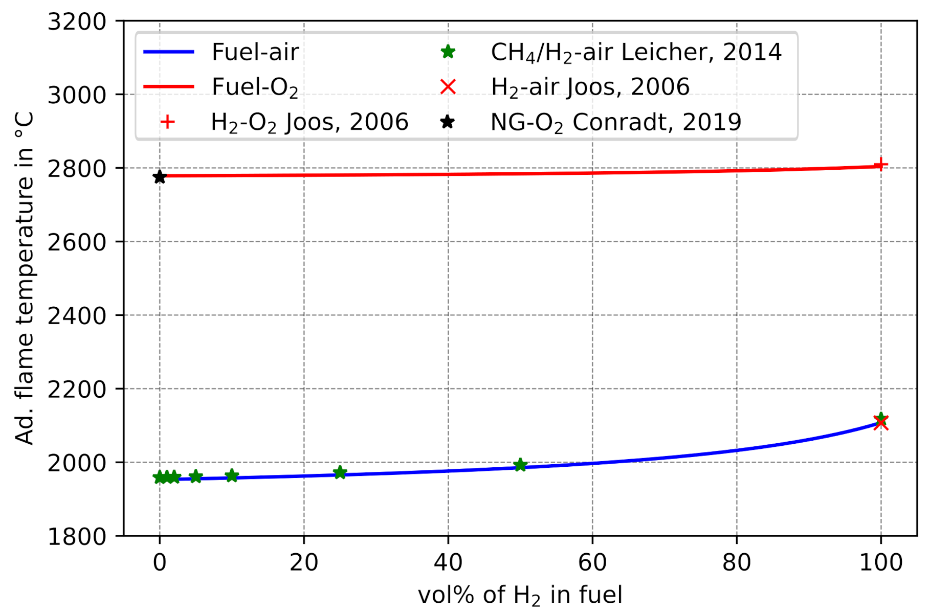
Figure 8 shows the comparison of the predicted T a d with literature values. For combustion of the fuel mixtures in ambient air (21 vol% O2, 79 vol% N2) T a d increases from approx. 1953 °C at 0 vol% H2 to approx. 2108 °C for pure H2-air combustion. This is due to both the more efficient oxidation of H
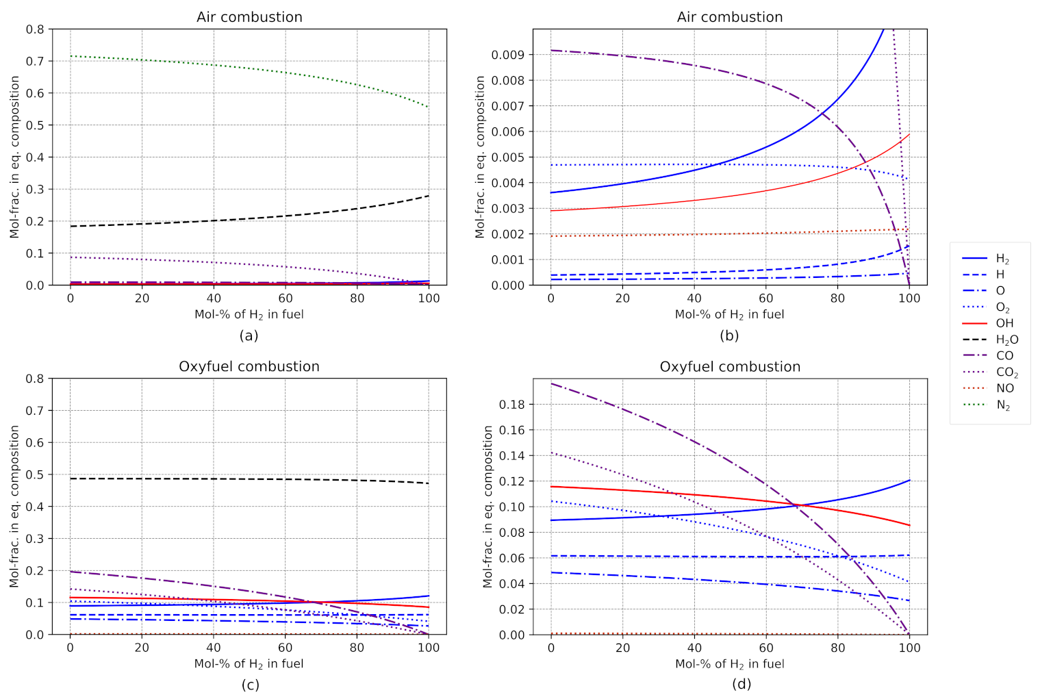
2 compared to hydrocarbon compounds, as well as the decreasing hydrocarbon compound concentrations in the fuel mixture. This assumption is substituted by the consideration of the detailed composition of combustion gases (Figure 9a,b). Oxyfuel combustion (Figure 8, red solid line) only yields a slight increase, from approx. 2779 °C at 0 vol% H2 to approx. 2804 °C for pure H2-O2 combustion. Based on the product gas composition after adiabatic combustion (Figure 9c,d), it can be concluded that other combustion products play a more important role in oxyfuel combustion than in combustion with common air, e.g., in oxyfuel combustion significantly more CO2 is formed than CO and no NO is present. Since CO2 formation is more efficient than CO formation, the increased T a d for oxyfuel combustion than for air combustion can be explained. Moreover, the almost complete absence of N2 at oxyfuel combustion significantly reduces the total heat capacity of the combustion gas mixture and therefore also increases T a d . Compared to air combustion, the exhaust gases of oxyfuel combustion are dominated by H compounds. Thus, the influences of higher H2 vol% in the fuel mixture are less significant than for common air combustion.
It can be concluded that the change from conventional air to oxyfuel combustion has a more significant impact on T a d than the addition of H2 to the fuel mixtures. Nevertheless, the sole consideration of T a d and the heating values are not sufficient to conclude the influences of high H2 contents in fuel mixtures for oxyfuel glass melting tanks.

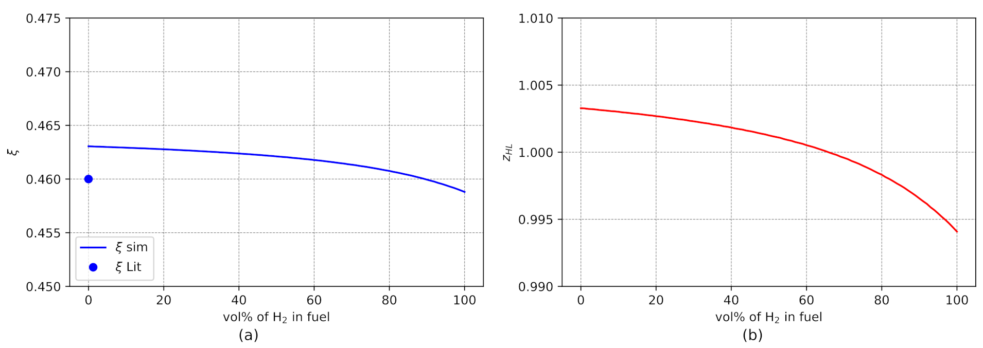
5.3. Influences on Furnace Efficiency

The operating efficiency of a glass melting furnace is further characterized by the dimensionless key indicators temperature efficiency ξ and heat capacity flow ratio z H L , as defined by Equations (8) and (9) [15]. Usually, ξ and z H L are considered constant in previous studies for a given combustion mode. The novelty of this work is the evaluation of ξ and z H L as a function of H2 vol% in the fuel rather than a constant (see Figure 10).
The calculated temperature efficiency of ξ = 0.463 (Figure 10a) shows a deviation of only 0.003 from literature data given in Ref. [15]. This is due to the fact that [15] assumed T a d = 2780 °C for oxyfuel combustion, whereas T a d was explicitly calculated as 2779 °C in this work. Moreover, as the calculated T a d varies only slightly ( Δ T a d = + 25 ° C ) for oxyfuel combustion, ξ also only decreases moderately to 0.459 for higher H2 contents in the fuel mixture. The heat capacity flow ratio z H L (Figure 10b) deviates by 0.003 from the ideal value of 1.000 for pure NG-O2 combustion and is, furthermore, within the typical range of 0.900–1.100 [15] for oxyfuel furnaces. At approx. 65 vol% H2 in the fuel, the ideal value of z H L = 1.000 is reached. At higher vol% of H2, z H L decreases to 0.994.
Based on the analysis of the key values ξ and z H L , it can be concluded that a higher H2 vol% in the fuel has only a minor effect on the furnace efficiency. However, besides these energetic effects, chemical changes in the furnace atmosphere were found to have a significant effect on the melting process at pure H2-O2 combustion [24]. As these chemical effects are not considered in this work, they should be investigated further in future studies.

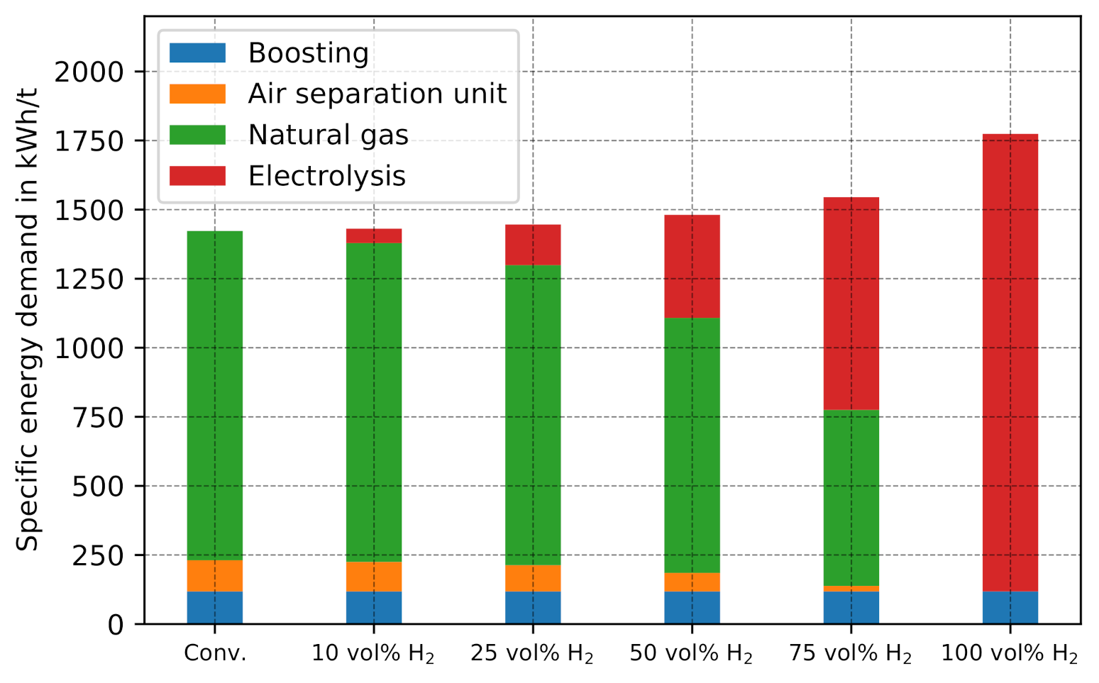
5.4. Specific Energy Demand

The change in specific energy demand resulting from the presented PtH2 concept is a major point of interest. To validate the models presented in this paper in terms of their ability to predict specific energy demand, the conventional scenario (Figure 11, first bar) is compared with literature data. The predicted total specific energy demand of 1423 kWh/t glass is in accordance with [62], which reported an average value of 1431 kWh/t glass for 300 container-glass furnaces, for predominantly conventional air combustion. The slightly lower specific energy demand of 8 kWh/t can be considered as a key indicator for the low prevalence of oxyfuel melting processes in the container glass industry. The low energy savings and comparatively high investments costs in oxygen infrastructure, as well as more expensive ceramics for the furnace brickwork, prevent a lucrative return of investment.
Figure 11 shows the changes of specific energy demand for the scenarios of 10, 25, 50, 75 and 100 vol% of H2 in the fuel mixture. The energy demand for electrical boosting remains constant in all scenarios (118 kWh/t glass), as it is modeled as a constant fraction of the total heat demand of melting. With increasing H2 vol% in the fuel mixture, the demand for natural gas decreases (1192 kWh/t glass to 0 kWh/t), while the energy demand of electrolysis increases (0 to 1656 kWh/t glass). Moreover, the energy demand of the ASU declines (113 kWh/t glass to approx. 0 kWh/t glass), since oxygen is obtained from electrolysis and less carbon has to be oxidized during combustion.

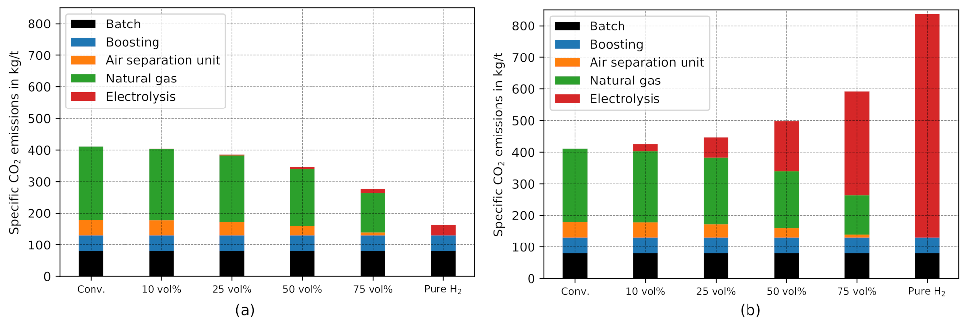
5.5. Specific CO2 Emissions

To validate the models presented in this paper in terms of their ability to predict the CO2 emissions, the conventional scenario (Figure 12, first bar) is compared with literature data [2]. In [2], energy-related CO2 emissions of 360 kg CO2-eq./t glass and process-related CO2 emissions of 80 kg CO2-eq./t glass were reported as average values for the container glass industry in Germany. Energy-related emissions include natural gas combustion, electrical boosting, and the ASU, whereas process-related emissions are caused by glass batch due to carbonate reactions. For the conventional scenario, the presented modeling approach predicts energy-related CO2 emissions of 331 kg CO2-eq./t (boosting: 50 kg CO2-eq./t glass, ASU: 48 kg CO2-eq./t glass, natural gas: 233 kg CO2-eq./t glass) and process-related emissions of 80 kg CO2-eq./t glass. The slightly decreased energy-related CO2 emissions are associated with the lower specific CO2 emissions for electricity assumed in Ref. [2] (512 g CO2-eq./kWh) compared to the present work (427 g CO2-eq./kWh). In addition, the slightly reduced energy demand of oxyfuel melting is a contributing factor. Moreover, as the deviation is still less then 10 % the validity of the simulation model is justified. It is not surprising that the predicted process-related CO2 emissions match literature data perfectly, given that these were set to a constant value of 80 kg CO2-eq./t glass throughout the entire simulations.
Moreover, the specific CO2 emissions were evaluated with respect to the electrical energy sources used. For renewable energy sources specific CO2 emissions of 19 g CO2-eq./kWh of electricity were assumed. By using renewable energy sources, specific emissions can be reduced from 411 kg CO2-eq./t glass to 163 kg CO2-eq./t glass for pure H2-O2 combustion, i.e., by 60% (Figure 12b). In contrast, if the energy demand of electrolysis is covered by electricity from the current German energy mix, the specific CO2 emissions even increases (Figure 12b). In this case, the scenario for pure H2-O2 combustion causes 837 kg CO2-eq./t glass, which is an increase of 104% compared to the conventional scenario. Thus, from an ecological perspective, the integration of PtH2 is only reasonable if renewable energy sources are used.

5.6. CO2 Abatement Costs
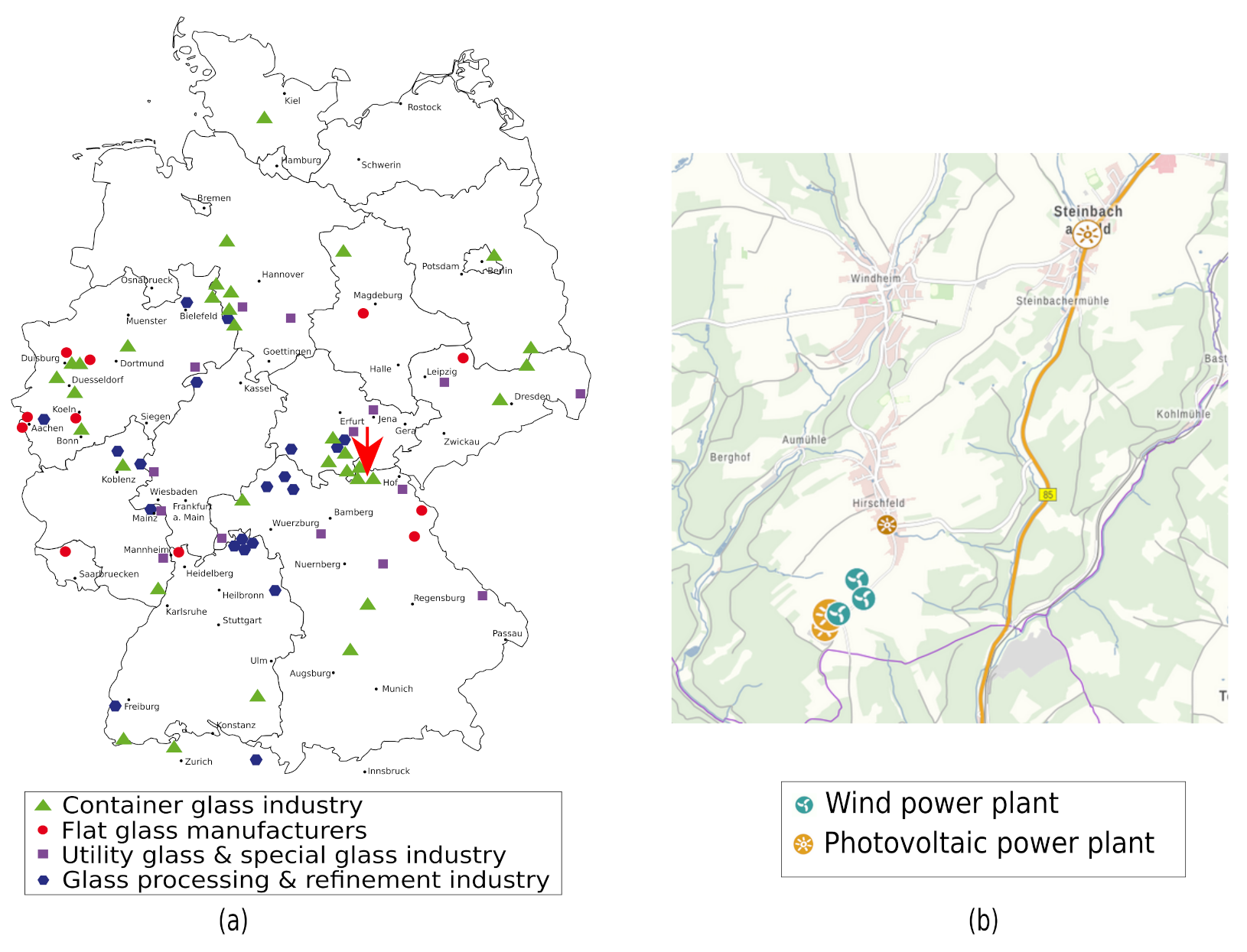
In a case study, CO2 abatement costs are calculated for Steinberg am Wald, county Kronach, Germany (latitude: 50.404387°, longitude: 11.332333°, WGS84 coordinates). This location can be considered as one of the main centers of the German container glass industry, as many companies are located here (Figure 4a). It is assumed that the energy demand for electrolysis to integrate PtH2 into oxyfuel glass melting is met by a nearby renewable energy park, i.e., three wind turbines and two PV systems (Figure 4b). The technical data from this is shown in Table 3.
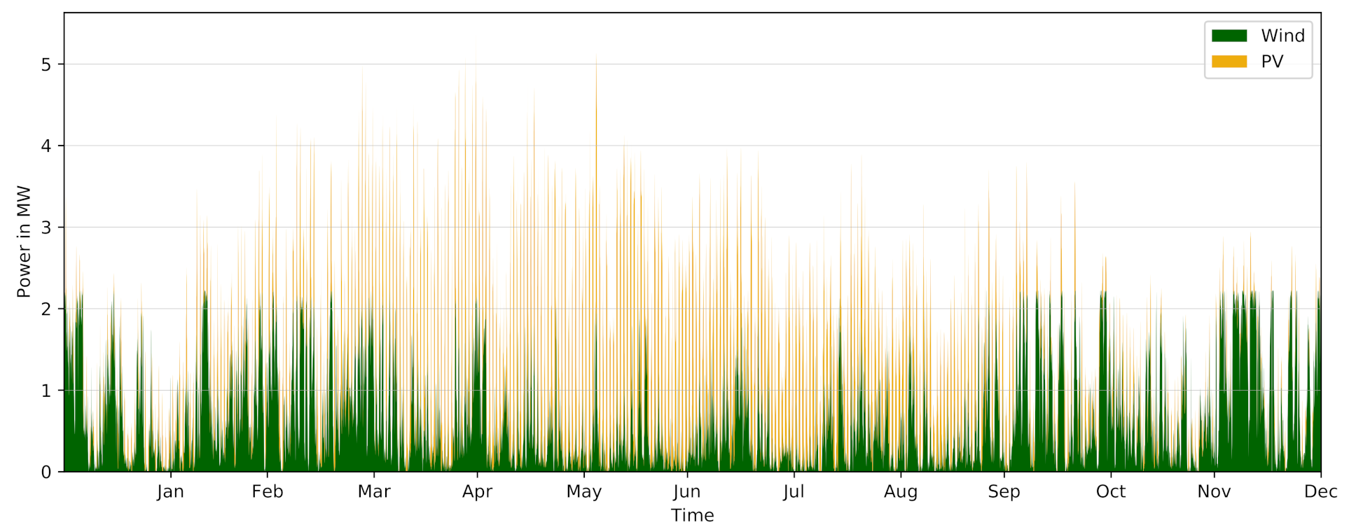
Based on the Modelica models described in Section 4.1, the energy output of these renewable energy parks during a TRY data set provided by DWD was determined for the selected location of the case study (Figure 13). The three wind power plants produce approx. 6100 MWh and the photovoltaic plants approx. 3900 MWh of electricity during a TRY.
Subsequently, these data sets were used as input variables for the optimization of the energy system presented in Figure 3. Due to the different years of construction and the, in part, lengthy operating time of these renewable energy sources, an approach based on the investment costs of the plants is highly error-prone. Therefore, an approach based on the current literature on the electricity production costs for renewable energies in Germany is chosen instead [63]. A price range of 0.035–0.063 €/kWh for electricity from open-field PV plants and 0.04–0.08 €/kWh for WP was reported [63]. Based values, as well as rather less favorable local factors for the renewable energy sources at the selected location (i.e., low solar irradiation of 1001–1020 W/m2, low wind speeds at 70 m hub height of about 8 m/s on average over TRY), electricity costs of 0.05 €/kWh from the described energy sources are assumed in the case study. Capital expenditures (CAPEX) and operational expenditures (OPEX) for electrolysis (≈1200 €/kW, [33]) and H2 ( storage (1100 €/kWh, [64]) are adopted from current literature. These cost parameters (i.e., electricity costs, CAPEX, OPEX) and the local energy profile (Figure 13), were subsequently used as input data in the OEMOF model.
Exemplary optimizations are performed for the 10 vol% H2 and the 25 vol% H2 scenario, respectively. Depending on the scenario, H2 storage capacity and electrolysis power changes resulting in different prices for the generated H2 (Table 4). The optimization based on the given TRY data set and the given high feed-in of renewable energy results in very high full load hours (FLH) of the electrolysis for both scenarios. Therefore, H2 costs are quite low in these scenarios.
To determine the energy costs of the initial scenario (i.e., oxyfuel glass melting with no integration of PtH2), assumptions had to be made regarding the energy costs of glass manufacturers. The energy demand of the glass industry is currently mainly covered by natural gas (see Section 1). Therefore, German glass companies are not commonly considered energy-intensive in terms of electricity demand, and hardly benefit from exemptions from German energy taxes. As a result, a value of 0.12 €/kWh is assumed for electricity costs. No taxes, levies, or charges are considered for the electricity production costs from renewable energy sources. Further, 0.03 €/kWh for natural gas and 0.10 €/m3 (STP) of O2, generated by ASU are assumed. The results of this specific cost distribution for the different estimated scenarios are shown in Table 5.
The integration of PtH2 into oxyfuel melting with 10 vol% H2 and 25 vol% H2 yields high CO2 abatement costs of 295 €/t CO2 and 732 €/t CO2 in the case study, respectively. In the 10 vol% H2 scenario, this is due to the only slight reduction in CO2 emissions in combination with high costs for the PtH2 infrastructure. The further significant increase in CO2 abatement costs for the 25 vol% H2 scenario is associated with a significant increase in the required H2 storage capacity (factor of 100) and associated H2 generation costs (factor of 2.5) compared to the 10 vol% H2 scenario (see Table 4). However, it should be noted that due to the low electrolysis power required, comparatively high FLH of the electrolysis are achieved, e.g favoring the H2 generation costs in the 10 vol% H2 scenario. Moreover, storage capacity could be reduced for the 25 vol% scenario by repowering of the small-scale wind turbines.
In this work, the assessment of the CO2 abatement costs associated with the integration of PtH2 in oxyfuel glass production is based on the evaluation of a case study for a single location. However, this location was found not to offer the optimal conditions for this concept, e.g., with regard to the availability of renewable energy. At the same time, this enabled a neutral evaluation of the concept without artificial fine-tuning. Therefore, further factors and methods for increasing the profitability of integrating PtH2 into oxyfuel glass production are presented below:
  • A battery-storage concept for emission reduction of electrical boosting and ASU power supply should be considered. Through the associated use of renewable electricity, the remaining CO2 emissions of both ASU and electrical boosting can be significantly reduced.
  • The use of so-called green electricity plans that exhibit lower specific CO2 emissions for electricity supplied from the grid will allow a further reduction in CO2 emissions. In this context, electricity market-based control and optimization of the operating strategy for the PtH2 can provide further cost benefits.
  • Developments in electrolysis production technology through more intensive use of PtH2 in other sectors may result in a further reduction in CAPEX.
  • Political funding programs and changing situations of CO2 taxation should be taken into account.
Therefore, it is obvious that the concept presented in this work on integrating PtH2 into oxyfuel melting has a high techno-economic potential for improvement. Nevertheless, this process concept could pave the way for CO2 reduction in the glass industry or, ideally, even for completely CO2-neutral glass production.

6. Conclusions

In this work, a process concept for the step-wise integration of PtH2 processes into oxyfuel glass melting is presented, based on simulations. In this way, changes in specific energy demand and associated specific CO2 emissions can be evaluated as a function of the H2 content in the fuel mixture, the fuel composition, the combustion itself, and certain furnace parameters. The following conclusions can be drawn:
The addition of H2 to the fuel mixture has a less significant effect on the adiabatic flame temperature of oxyfuel combustion than on conventional fuel-air combustion. As the H2 content in the fuel increases, the specific energy demand caused by the PtH2 concept is expected to increase by a maximum of 25% compared to conventional oxyfuel glass melting scenarios. Using the PtH2 concept, CO2 emissions may decrease by up to 60% if required electricity is covered by renewable energy sources. However, when using the conventional German energy mix, CO2 emissions are twice as high as for conventional oxyfuel melting process.The integration of PtH2 concept in the glass industry still shows high ideal techno-economic development potential, e.g., with regard to large-scale renewable energy sources, intelligent storage concepts and optimized energy purchasing.
The findings of this study motivate future numerical and experimental studies on the influences of high H2 amounts in the fuel mixture on glass-industry-specific combustion systems.

Author Contributions

Conceptualization, S.G. and M.H.; Data curation, S.G.; Formal analysis, S.G.; Funding acquisition, S.G. and M.S.; Investigation, S.G.; Methodology, S.G., D.R., M.H. and M.S.; Project administration, M.S.; Resources, M.G., B.D., A.H. and M.S.; Software, A.H.; Supervision, M.G., B.D., A.H. and M.S.; Validation, S.G., D.R. and A.H.; Visualization, S.G. and M.H.; Writing—original draft, S.G.; Writing—review & editing, D.R., M.H., M.G., B.D., A.H. and M.S. All authors have read and agreed to the published version of the manuscript.

Funding

This research was funded by a scholarship from the Nagelschneider Foundation and by the Regensburg Center of Energy and Resources (RCER) of the Ostbayerische Technische Hochschule (OTH) Regensburg, within the scope of a Pre-Doctoral scholarship. The authors would like to acknowledge the financial support received from the Nagelschneider Foundation and the RCER.

Acknowledgments

Stefan Schmitt of Schott AG, Mainz, should be thanked for his advice on technical issues relating to the glass processes. We would also like to thank Albert Biber from the Chair of Energy Systems (LES) at the Technical University of Munich, who provided valuable advice on the use of Cantera software.

Conflicts of Interest

The authors declare no conflict of interest.

Abbreviations

The following abbreviations are used in this manuscript:
ACAlternating current
ASUAir separation unit
CAPEXCapital expenditures
DCDirect current
DWDGerman metrological service
EACEquivalent annual cost factor
EEXEuropean energy exchange
EU-ETSEuropean Union emission trading system
FLHFull load hours
GCVGross calorific values
ICVLHVInferior calorific Lower heating value
MSLModelica standard library
OEMOFOpen energy modeling framework
OPEXOperational expenditures
PEMProton exchange membrane
PtH2Power-to-Hydrogen
PVPhotovoltaic
SCMSubmerged combustion melter
STPStandard temperature and pressure conditions ( 0 °C and 1.013 bar)
TCRThermochemical reformation
TRYTest reference year
WPWind power

References

  1. Federal Association of the German Glas Industry (BV Glas). Jahresbericht 2019—Annual Report 2019. Berlin, Duesseldorf. 2020. Available online: https://www.bvglas.de/presse/publikationen/ (accessed on 3 November 2021).
  2. Leisin, M. Energiewende in der Industrie: Branchensteckbrief der Glasindustrie. Available online: https://www.bmwi.de/Redaktion/DE/Downloads/E/energiewende-in-der-industrie-ap2a-branchensteckbrief-glas.pdf?__blob=publicationFile&v=4 (accessed on 11 November 2021).
  3. Scalet, B.M.; Garcia, M.M.; Sissa, A.; Roudier, S.; Delgardo Sancho, L. Best Available Techniques (BAT) Reference Document for the Manufacture of Glass, 3rd ed.; European Comission, Joint Research Center: Seville, Spain, 2013; p. 485. ISBN 978-9-279282-84-3. [Google Scholar]
  4. Ausfelder, F.; Seitz, A.; von Roon, S. Bericht des AP V.6: “Flexibilitätsoptionen und Perspektiven in der Grundstoffindustrie” im Kopernikus-Projekt “SynErgie—Synchronisierte und Energieadaptive Produktionstechnik”, 1st ed.; DECHEMA Gesellschaft für Chemische Technik und Biotechnologie e.V.: Frankfurt am Main, Germany, 2018; p. 296. ISBN 9783897462069. [Google Scholar]
  5. Deutsche Emissionshandelsstelle (DEHSt). Treibhausgasemissionen 2019. Emissionshandelspflichtige Stationäre Anlagen und Luftverkehr in Deutschland (VET-Bericht 2019); DEHst im Umweltbundesamt: Berlin, Germany, 2020. [Google Scholar]
  6. Bach, S.; Isaak, N.; Kemfert, C.; Kunert, U.; Schill, W.-P.; Wägner, N.; Zaklan, A. Für eine Sozialverträgliche CO2-Pepreisung. Politikberatung Kompakt, 1st ed.; Deutsches Institut für Wirtschaftsforschung (DIW): Berlin, Germany, 2019; ISBN 978-3-946417-29-3. [Google Scholar]
  7. Lindig, M. Glass melting technology addressing the environmental trend electro. In Proceedings of the 91st Glas Technology Meeting of DGG, Weimar, Germany, 29–31 May 2017. [Google Scholar]
  8. Schmitz, A.; Kamiński, J.; Maria Scalet, B.; Soria, A. Energy consumption and CO2 emissions of the European glass industry. Energy Policy 2011, 39, 142–155. [Google Scholar] [CrossRef]
  9. Jamshidi, A.; Kurumisawa, K.; Nawa, T.; Igarashi, T. Performance of pavements incorporating waste glass: The current state of the art. Renew. Sustain. Energy Rev. 2016, 64, 211–236. [Google Scholar] [CrossRef]
  10. Stormont, R. Electricity in Glass Making . . . often the Low-Cost Option. In Proceedings of the 39th ASEAN Glass Conference of the ASEAN Federation of Glass Manufacturers (AFGM), Cebu, Philippines, October 2015; Available online: http://www.aseanglass.org/wp-content/uploads/2017/08/39th-ASEAN-Glass-5.-Electricity-in-Glass-Making-...-often-the-Low-Cost-Option-Electroglass-Ltd-by-Mr.-Richard-Stormont.pdf (accessed on 11 November 2021).
  11. Trier, W. Glasschmelzöfen, 1st ed.; Springer: Berlin, Germany, 1984; p. 324. ISBN 978-3-642-82068-7. [Google Scholar]
  12. Nikolaus Sorg GmbH. Glass Melting Technology. 2016. Available online: https://www.sorg.de/content/uploads/2016/09/Glas%7B%5C_%7DMelting.pdf (accessed on 9 September 2021).
  13. Horn Glass Industries GmbH. Melting and Conditioning—Furnaces. Available online: https://www.hornglass.com/melting-conditioning/furnaces (accessed on 9 September 2021).
  14. Beerkens, R. Energy saving options for glass furnaces and recovery of heat from their flue gases—And experiences with batch and cullet preheaters applied in the glass industry. In Proceedings of the 69th Conference on Glass Problems, Columbus, OH, USA, 4–5 November 2008; Drummond, C.H., Ed.; John Wiley & Sons: Hoboken, NJ, USA, 2009. ISBN 978-0-470-45751-1. [Google Scholar]
  15. Conradt, R. Prospects and physical limits of processes and technologies in glass melting. J. Asian Ceram. Soc. 2019, 7, 377–396. [Google Scholar] [CrossRef] [Green Version]
  16. Schep, J.J. Experiences with an oxygen-fired container glass furnace with silica crown: 14 years—A world record? In Proceedings of the 69th Conference on Glass Problems, Columbus, OH, USA, 4–5 November 2008; Drummond, C.H., Ed.; John Wiley & Sons: Hoboken, NJ, USA, 2019. ISBN 978-0-470-45751-1. [Google Scholar]
  17. Schmitt, S. Flexibler Einsatz verschiedener Energiearten in der Spezialglasindustrie—Ein Ausblick in die Zukunft. In Linde Expertenforum Glas; Linde AG: Merseburg, Germany, 2017. [Google Scholar]
  18. Giese, A. Untersuchungen zur Verbesserung der Energieeffizienz und der Wämeubertragung einer Oxy-Fuel-Glasschmelzwanne. Available online: https://www.gwi-essen.de/fileadmin/dateien/abschlussberichte/Abschlussbericht_O2Glaswanne_final-1.pdf (accessed on 9 September 2021).
  19. Gonzales, A. Optimelt Regenerative thermo-chemical heat recovery for oxy-fuel glass furnaces. In Proceedings of the 75th Conference on Glass Problems, Columbus, OH, USA, 3–6 November 2014; Sundaram, S.K., Ed.; John Wiley & Sons: Hoboken, NJ, USA, 2014; pp. 113–120, ISBN 978-1-119-11747-6. [Google Scholar] [CrossRef]
  20. Caumont-prim, C.; Paubel, X.; Lâm, T.; Juma, S.; Jarry, L. HeatOx technology makes major efficiency strides. Glass Worldw. 2018, 5/6, 78–80. [Google Scholar]
  21. Teschner, R. Glasfasern, 1st ed.; Springer: Berlin, Germany, 2013; p. 205. ISBN 978-3-642-38328-1. [Google Scholar]
  22. Wesseling, J.H. The transition of energy intensive processing industries towards deep decarbonization: Characteristics and implications for future research. Renew. Sustain. Energy Rev. 2017, 79, 1303–1313. [Google Scholar] [CrossRef]
  23. Fleischmann, B. Neuer Ansatz zur Bilanzierung des Energieeinsatzes bei der Glasherstellung und der Versuch der geschlossenen Darstellung von Kennzahlen aus der Produktionstechnik und aus statistischen (Wirtschafts-) Daten. HVG-Mitteilungen 2018, 2173, 1–18. [Google Scholar] [CrossRef]
  24. Krogel, S.; Roos, C. Large lab-scale glass melting with hydrogen-oxygen combustion. In Proceedings of the Joint Meeting of DGG-USTV, Nürnberg, Germany, 13–15 May 2019; Hüttentechnische Vereinigung der Glasindusrie e.V. (HVG) Offenbach: Nürnberg, Germany, 2019. [Google Scholar]
  25. Beerkens, R. Analysis of elementary process steps in industrial glass melting tanks—Some ideas on innovations in industrial glass melting. Ceram. Silik. 2008, 52, 206–217. [Google Scholar]
  26. Minegishi, S. Method and Apparatus for Melting Glassy Materials by a Rotary Kiln. U.S. Patent 3,508,742A, 28 April 1967. [Google Scholar]
  27. Gonterman, J.R.; Weinstein, M.A.; High Intensity Plasma Glass Melter Project. Final DOE. Available online: https://www.osti.gov/servlets/purl/894643 (accessed on 9 September 2021).
  28. Rue, D.; Kunc, W.; Aronchik, G. Operation of a Pilot-Scale Submerged Combustion Melter. In Proceedings of the 68th Conference on Glass Problems, Columbus, OH, USA, 16–17 October 2007; Drummond, C.H., Ed.; John Wiley & Sons: Hoboken, NJ, USA, 2009. ISBN 978-0-470-34491-0. [Google Scholar]
  29. Muijsenberg, E.; Mahrenholtz, H.; Jandacek, P.; Hakes, S.; Jatzwauk, C. Options for a step wise CO2 emission reduction. In Proceedings of the Joint Meeting of DGG-USTV, Nürnberg, Germany, 13–15 May 2019; Hüttentechnische Vereinigung der Glasindusrie e.V. (HVG) Offenbach: Nürnberg, Germany, 2019. [Google Scholar]
  30. Kopernikus-Projekte für die Energiewende. DisConMelter. Available online: https://geschichten.ptj.de/disconmelter#150748 (accessed on 9 September 2021).
  31. Sterner, M. Bioenergy and Renewable Power Methane in Integrated 100% Renewable Energy Systems. Ph.D. Thesis, University of Kassel, Kassel, Germany, 23 September 2009. [Google Scholar]
  32. Sterner, M.; Stadler, I. Energiespeicher—Bedarf, Technologien, Integration, 2nd ed.; Springer: Berlin, Germany, 2017; p. 876. ISBN 978-3-662-48893-5. [Google Scholar]
  33. Thema, M.; Bauer, F.; Sterner, M. Power-to-Gas: Electrolysis and methanation status review. Renew. Sustain. Energy Rev. 2019, 112, 775–787. [Google Scholar] [CrossRef]
  34. Buttler, A.; Spliethoff, H. Current status of water electrolysis for energy storage, grid balancing and sector coupling via power-to-gas and power-to-liquids: A review. Renew. Sustain. Energy Rev. 2018, 82, 2440–2454. [Google Scholar] [CrossRef]
  35. Fleischmann, B. Einfluss von Gasbeschaffenheitsänderungen auf industrielle Prozessfeuerungen am Beispiel der Glasindustrie. DVGW Energ. Wasser Prax. 2013, 64, 158–161. [Google Scholar]
  36. Müller-Syring, G.; Henel, M.; Krause, H.; Rasmusson, H.; Mlaker, H.; Köppel, W.; Höcher, T.; Sterner, M.; Trost, T. Power-to-Gas: Entwicklung von Anlagenkonzepten im Rahmen der DVGW-Innovationsoffensive. gwf-Gas|Erdgas 2011, 11, 770–777. [Google Scholar]
  37. Täschner, I. Erdgas—Zahlen, Daten, Fakten; Bundesverband der Energie- und Wasserwirtschaft (BDEW) e.V.: Berlin, Germany, 2019; Available online: https://issuu.com/bdew_ev/docs/8_erdgastechnik-zahlen-daten-fakten (accessed on 9 September 2021).
  38. Modelica Association. Modelica Language Specification. Version 3.5. 2021. Available online: https://modelica.org/documents/MLS.pdf (accessed on 9 September 2021).
  39. Krien, U.; Schönfeldt, P.; Launer, J.; Hilpert, S.; Kaldemeyer, C.; Pleßmann, G. oemof.solph—A model generator for linear and mixed-integer linear optimisation ofenergy systems. Softw. Impacts 2020, 6, 100028. [Google Scholar] [CrossRef]
  40. Deutscher Wetterdienst (DWD). Projektbericht: Ortsgenaue Testreferenzjahre von Deutschland für Mittlere und Extreme Witterungsverhältnisse. 2017. Available online: https://www.dwd.de/DE/leistungen/testreferenzjahre/testreferenzjahre.html (accessed on 9 September 2021).
  41. Brkic, J.; Ceran, M.; Elmoghazy, M.; Kavlak, R.; Haumer, A.; Kral, C. Open Source PhotoVoltaics Library for Systemic Investigations. In Proceedings of the 13th International Modelica Conference, Regensburg, Germany, 4–6 March 2019; Linköping University Electronic Press: Linköping, Sweden, 2019. ISBN 978-91-7685-122-7. [Google Scholar] [CrossRef] [Green Version]
  42. Liu, B.Y.H.; Jordan, R.C. The interrelationship and characteristic distribution of direct, diffuse and total solar radiation. Sol. Energy 1960, 4, 1–19. [Google Scholar] [CrossRef]
  43. Andresen, L.; Dubucq, P.; Garica, R.P.; Ackermann, G.; Kather, A.; Schmitz, G. Transientes Verhalten gekoppelter Energienetze Mit Hohem Anteil Erneuerbarer Energien. Available online: https://www.tuhh.de/transient-ee/Abschlussbericht_TransiEntEE.pdf (accessed on 9 September 2021).
  44. ResilientEE—The TransiEnt Library. Available online: https://www.tuhh.de/transient-ee/ (accessed on 1 April 2021).
  45. Memmler, M.; Lauf, T.; Schneider, S. Emissionsbilanz erneuerbarer Energieträger 2017. Clim. Chang. 2018, 23. Available online: https://www.umweltbundesamt.de/sites/default/files/medien/1410/publikationen/2018-10-22_climate-change_23-2018_emissionsbilanz_erneuerbarer_energien_2017_fin.pdf (accessed on 8 May 2021).
  46. Hau, E. Windkraftanlagen—Grundlagen, Technik, Einsatz, Wirtschaftlichkeit, 6th ed.; Springer: Berlin, Germany, 2016; p. 1009. ISBN 978-3-662-53154-9. [Google Scholar] [CrossRef]
  47. Eberhart, P.; Chung, T.S.; Haumer, A.; Kral, C. Open Source Library for the Simulation of Wind Power Plants. In Proceedings of the 11th International Modelica Conference, Versailles, France, 21–23 September 2015; Linköping University Electronic Press: Linköping, Sweden, 2015. ISBN 978-91-7685-955-1. [Google Scholar] [CrossRef] [Green Version]
  48. Energieatlas Bayern. Available online: https://geoportal.bayern.de/energieatlas-karten/?wicket-crypt=PBbnymGWFSQ (accessed on 1 July 2021).
  49. Vogl, V.; Ahman, M.; Nilsson, L.J. Assessment of hydrogen direct reduction for fossil-free steel making. J. Clean. Prod. 2018, 203, 736–745. [Google Scholar] [CrossRef]
  50. Aneke, M.; Meihong, W. Potential for improving the energy efficiency of cryogenic air separation unit (ASU) using binary heat recovery cycles. Appl. Therm. Eng. 2015, 81, 223–231. [Google Scholar] [CrossRef]
  51. Icha, P.; Kugs, G. Entwicklung der spezifischen Kohlendioxid-Emissionen des deutschen Strommix in den Jahren 1990–2019. Clim. Chang. 2020, 13, 29. [Google Scholar]
  52. Conradt, R. The industrial glass melting process. In The SGTE Casebook: Thermodynamics at Work, 2nd ed.; Hack, K., Ed.; Woodhead Publishing Limited: Cambridge, UK, 2012; ISBN 978-1-84569-395-4. [Google Scholar]
  53. Conradt, R. Thermal versus chemical constraints for the efficiency of industrial glass melting furnaces. In Proceedings of the 9th International Conference on Advances in the Fusion and Processing of Glass, Cairns, Australia, 10–14 July 2011; Varshneya, A.K., Schaeffer, H.A., Richardson, K.A., Wightman, M., Pye, L.D., Eds.; John Wiley & Sons: Hoboken, NJ, USA, 2012. ISBN 978-1-118-27374-6. [Google Scholar]
  54. Joos, F. Technische Verbrennung, 1st ed.; Springer: Berlin, Germany, 2006; ISBN 978-3-540-34333-2. [Google Scholar]
  55. Lucas, K. Thermodynamik, 7th ed.; Springer: Berlin, Germany, 2008; ISBN 978-3-540-68645-3. [Google Scholar]
  56. Goodwin, D.G.; Speth, R.L.; Moffat, H.K.; Weber, B.W. Cantera: An Object-oriented Software Toolkit for Chemical Kinetics, Thermodynamics, and Transport Processes. Version 2.5.1. 2021. Available online: https://www.cantera.org (accessed on 16 September 2021).
  57. Smith, G.P.; Golden, D.M.; Frenklach, M.; Moriarty, N.W.; Eiteneer, B.; Goldenberg, M.; Bowman, C.T.; Hanson, R.K.; Song, S.; Gardiner, W.C.; et al. GRI-MECH 3.0. Available online: http://www.me.berkeley.edu/gri_mech/ (accessed on 9 September 2021).
  58. Deutsches Institut für Normung (DIN). DIN 1310: Zusammensetzung von Mischphasen; Deutsches Institut für Normung (DIN): Berlin, Germany, 1984. [Google Scholar] [CrossRef]
  59. Huang, K.S.; Kuo, L.; Chou, K.L. The applicability of marginal abatement cost approach: A comprehensive review. J. Clean. Prod. 2016, 127, 59–71. [Google Scholar] [CrossRef]
  60. Zhou, D.; Li, T.; Huang, D.; Wu, Y.; Huang, Z.; Xiao, W.; Wang, Q.; Wang, X. The experiment study to assess the impact of hydrogen blended natural gas on the tensile properties and damage mechanism of X80 pipeline steel. Int. J. Hydrogen Energy 2021, 46, 7402–7414. [Google Scholar] [CrossRef]
  61. Leicher, J.; Giese, A. Einfluss von Gasbeschaffenheitsänderungen auf den Glasherstellungsprozess. HVG-Mitteilungen 2014, 2164, 1–9. [Google Scholar] [CrossRef]
  62. Beerkens, R. New Concepts for Energy Efficient and Emission Friendly Melting of Glass. In Proceedings of the 9th International Conference on Advances in the Fusion and Processing of Glass, Cairns, Australia, 10–14 July 2011; Varshneya, A.K., Schaeffer, H.A., Richardson, K.A., Wightman, M., Pye, L.D., Eds.; John Wiley & Sons: Hoboken, NJ, USA, 2012. ISBN 978-1-118-27374-6. [Google Scholar]
  63. Fraunhofer ISE. Stromgestehungskosten Erneuerbare Energien. Available online: https://nachrichten.idw-online.de/2021/06/22/stromgestehungskosten-erneuerbare-energien-aufgrund-steigender-co2-kosten-den-konventionellen-kraftwerken-deu/ (accessed on 9 September 2021).
  64. Zakeri, B.; Sanna, S. Electrical energy storage systems: A comparative life cycle cost analysis. Renew. Sustain. Energy Rev. 2015, 42, 569–596. [Google Scholar] [CrossRef]
Figure 1. Historical development of specific energy demand and specific CO2 emissions based on data from the glass industry in the EU across the overall glass sectors (e.g., glass fibers, container glass, special glass). Adapted with the permission of Ref. [7]. Copyright 2017 M.Lindig.
Energies 14 08603 g001
Figure 2. Efficiencies of fuel-fired and electric furnaces as a function of pull rate, adapted from Ref. [10]. In this work, a melting tank efficiency η M T of 42% is assumed for a 100 t/d oxyfuel melting system (see Section 4.4.1).
Energies 14 08603 g002
Figure 3. Basic flow sheet for the integration of Power-to-Hydrogen (PtH2) into oxyfuel glass melting processes.
Energies 14 08603 g003
Figure 4. (a) Distribution of the glass industry in Germany, highlighting the selected location (red arrow, Steinberg am Wald) for the case study of the exemplary evaluation of CO2 abatement costs [1].(b) Emergence of renewable energy in the vicinity of the selected case study site (i.e., Steinberg am Wald, latitude: 50.404387°, longitude: 11.332333°, WGS84 coordinates) [48].
Energies 14 08603 g004
Figure 5. Efficiencies of fuel-fired and electric furnaces as a function of pull rate, adapted from Ref. [10]. In this work, a melting tank efficiency η M T of 42% is assumed for a 100 t/d oxyfuel melting system (see Section 4.4.1).
Energies 14 08603 g005
Figure 6. Block diagram of the OEMOF energy system.
Energies 14 08603 g006
Figure 7. Predicted changes in mass- and volume-related gross calorific values (GCV) and inferior calorific (ICV) with increasing H2 vol% in the fuel mixture, compared to literature data given in Leicher, 2014 [61].
Energies 14 08603 g007
Figure 8. Comparison of the predicted adiabatic flame temperatures with increasing H2 vol% in the fuel mixture with literature values for CH4/H2-air combustion (Leicher, 2014 [61]), pure H2-air combustion (Joos, 2006 [54]) and natural gas (NG)-air combustion (Conradt, 2019 [15]).
Energies 14 08603 g008
Figure 9. Predicted equilibrium composition of the gas mixtures after adiabatic combustion. (a) Main products of fuel-air combustion, with N2, H2O and CO2 being the dominant products. (b) Highlight of the minor products of fuel-air combustion, i.e., CO, O2, H2, OH, NO, H and O. Despite their low mole fractions, CO and NO, in particular, have a significant impact on adiabatic flame temperatures. The other species can be considered negligible for adiabatic flame temperature investigations. (c) Main products of fuel-oxyfuel combustion with H2O, CO, CO2, OH and O2 being dominating products. (d) Highlight of the minor products of fuel-oxyfuel combustion, i.e., H2, H and O.
Energies 14 08603 g009
Figure 10. (a) Temperature efficiency ξ with increasing H2 shares in fuel, compared to a literature value for oxyfuel combustion given in Ref. [15]. (b) Heat capacity flow ratio z H L with increasing vol% of H2 in fuel for a normalized pull of ϕ = 1.0 . Ideal values are reached for z H L 1.00 . Literature values of z H L for oxyfuel fired furnaces range between 0.85 and 1.15 [15].
Energies 14 08603 g010
Figure 11. Comparison of the proportional specific energy demand per ton of molten glass caused by boosting, air separation unit (ASU), natural gas and electrolysis between the integration of PtH2 in oxyfuel-based glass melting processes with various H2 vol% in the fuel mixture and the conventional scenario (i.e., 0 vol% H2 in the fuel mixture).
Energies 14 08603 g011
Figure 12. (a) Specific CO2 emissions with the energy demand for electrolysis being covered by wind and PV (19 g CO2-eq./kWh). (b) Specific CO2 emissions with the energy demand for electrolysis energy demand being covered by the current German energy mix (427 g CO2-eq./kWh [51]).
Energies 14 08603 g012
Figure 13. Calculated generated power of wind power and photovoltaic plants during a test reference year (TRY) at the selected location of the case study (Steinberg am Wald, latitude: 50.404387° longitude: 11.332333° (WGS84)).
Energies 14 08603 g013
Table 1. Comparison of key values for established melting tank designs. As efficiency depends on several factors (e.g., glass type, melting capacity, fuel) only a qualitatively assessment can be provided. An increasing number of “+” indicates higher efficiency [12,13,14,15,16,17,18].
RegenerativeRecuperativeOxyfuelAll-Electric
Heat-exchangerdirect contactindirect contactnonenone
systemceramic latticedual shell,
structureshell-and-tube
Burner arrangementU-flame,U-flame,cross-firednone
cross firedcross fired
Industry sectorFlat-, container-,Container- andspecial glassspecial glass
fiber-, special-special-glass
glass
Efficiency++++++++++
Table 2. Composition of fuel mixtures in the analyzed scenarios. Each composition is given in mole fractions x i (mol/mol fuel). Mole fractions are equivalent to volume fractions φ i at standard conditions (STP, 0 °C and 1.013 bar). The initial composition of natural gas H from Russia for the conventional scenario is adapted from [37].
ComponentConventionalScenarioScenarioScenarioScenarioScenario
0 vol% H210 vol% H2 25 vol% H2 50 vol% H2 75 vol% H2 100 vol% H2
mol/molmol/molmol/molmol/molmol/molmol/mol
Methane (CH4)0.96420.86780.72380.48220.24100.0000
Ethane (C2H6)0.02580.02320.01930.01290.00650.0000
Propane (C3H8)0.00170.00150.00130.00080.00040.0000
Carbon dioxide (CO2)0.00330.00300.00250.00160.00080.0000
Nitrogen (N2)0.00500.00450.00370.00260.00130.0000
Hydrogen (H2)0.00000.10000.25000.50000.75001.0000
Table 3. Renewable energy sources at the selected location (i.e., Steinberg am Wald, latitude: 50.404387°, longitude: 11.332333°) [48].
PlantNominal PowerHub HeightYear of Construction
in kWin m
Wind powerAN Bonus 600600582001
AN Bonus 600600582001
AN Bonus 10001000702001
Total:2200
Photovoltaic,Plant 12997 2017
open fieldPlant 2538 2007
Total:3535
Table 4. Parameters of the optimized PtH2 integration into oxyfuel glass-melting processes for the boundary conditions (location, renewable energy sources, TRY) with respect to cost minimization.
UnitScenarioScenario
10 vol% H225 vol% H2
PEM input powerkW272966
PEM electrolysis FLHh69795544
Used energy of total supply%1953
H2 Storage capacityMWh4.65500.00
H2 Costs€/kWh0.0920.224
€/m3 STP0.280.67
€/kg H23.077.48
Table 5. Comparison of the various and total specific energy costs and CO2 abatement costs of the conventional scenario (i.e., merely oxyfuel glass melting) with the scenarios including the integration of a PtH2 into oxyfuel glass melting with 10 vol% H2 and 25 vol% H2 in the fuel mixture, respectively.
Conventional Scenario10 vol% H2 Scenario25 vol% H2 Scenario
DemandSpecific CostsDemandSpecific CostsDemandSpecific Costs
€/t Glass €/t Glass €/t Glass
Boosting118 kWh/t glass14.16118 kWh/t glass14.16118 kWh/t glass14.16
Natural gas1192 kWh/t glass35.761154 kWh/t glass34.621086 kWh/t glass32.58
O2 from ASU243 m3/t glass24.30240 m3/t glass24.00220 m3/t glass22.00
H20 kWh/t glass0.00156 kWh/t glass3.50106 m3/t glass23.78
Total 74.22 76.28 92.52
CO2 em.411 kg CO2-eq./t glass404 kg CO2-eq./t glass386 kg CO2-eq./t glass
CO2 ab. costs 295 €/t CO2732 €/t CO2
Publisher’s Note: MDPI stays neutral with regard to jurisdictional claims in published maps and institutional affiliations.

