1. Introduction
Transport telematics systems and electronic security systems (ESS) located in a metal container on a railway route are considered to be the “State’s critical infrastructure items” [
1,
2,
3]. Their most important task is to ensure the security of vehicle movement on railway routes [
4,
5]. They are located in a special, structurally reinforced metal container and are protected against the action of external and internal destructive factors. ESS elements can also be found inside buildings and in a publicly available external environment, where they are exposed to variable environmental parameters—temperature [
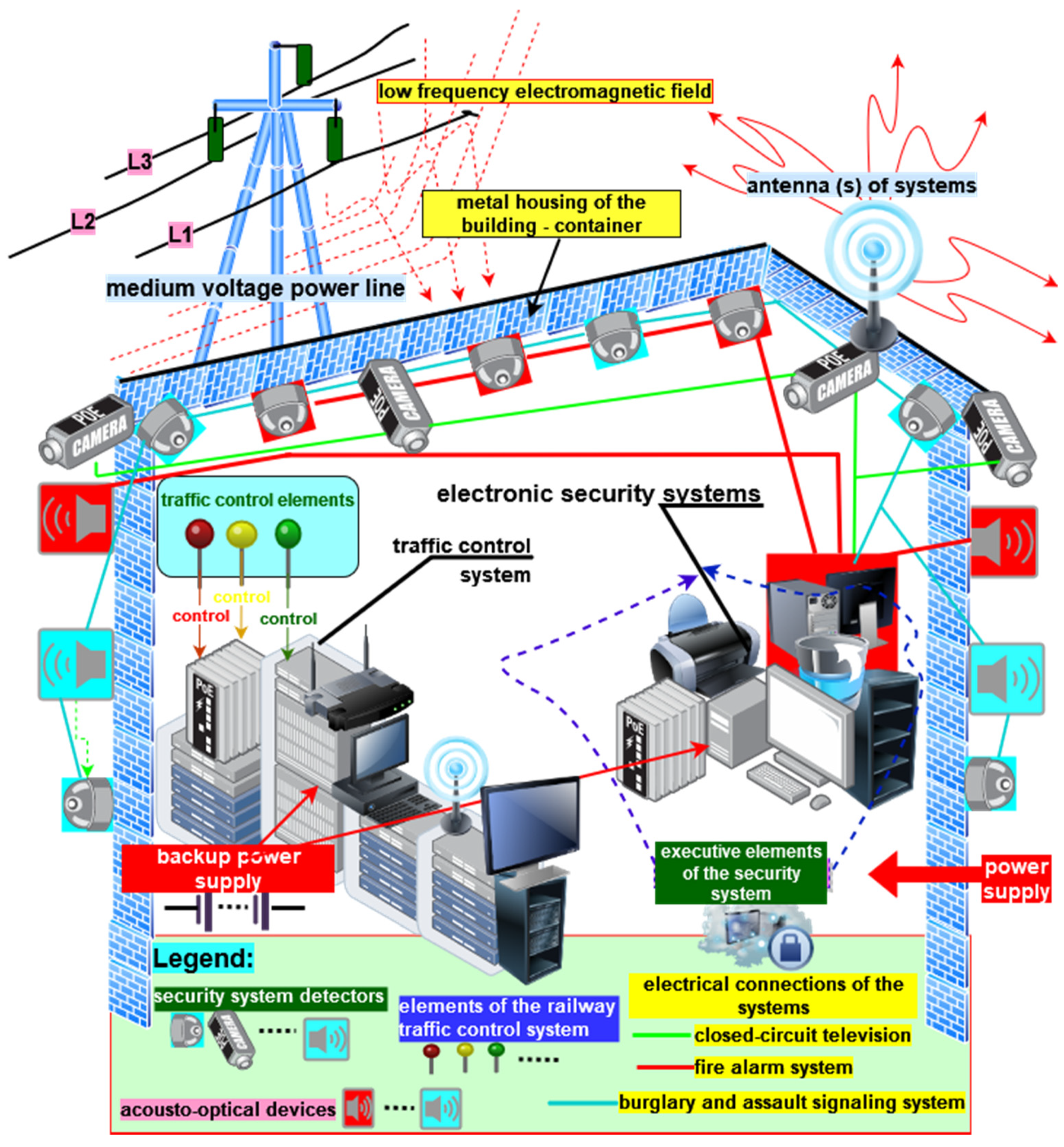
6], humidity, etc., as well as the unintentional low-frequency electromagnetic field generated by medium voltage—15, 30 kV—power lines. These lines are a supply source for the aforementioned systems (
Figure 1) [
7].
Transport telematics systems and electronic security systems are supplied from the 15 kV or 30 kV medium-voltage grid. The overhead power line is 5 or 10 m away from the container where the aforementioned electronic systems are located, in accordance with applicable national standards that apply to ensuring protection against the impact of unintentional electromagnetic field on living and inanimate organisms. A transformer located outside the container ensures an appropriate voltage level—230 V electronic power supplies. Backup power supply in the form of battery banks for electronic security systems is provided in order to guarantee the high reliability of telematics systems and ESS in the container. It consists of a fire alarm system (FAS) [
8,
9], an intrusion detection system (IDS), and closed-circuit television (CCTV). Battery banks should exhibit sufficient capacity that is determined in accordance with applicable standards (taking into account detection and alarm currents that should be ensured for a specified operation period of these systems). Due to the higher consumption of working currents by telematics systems, the backup power supply is provided within such a technical facility by UPS devices. Both battery banks and UPS devices are technically organized in a manner sufficient for the purposes of guaranteeing an adequate operational safety level by providing power supply continuity. In order to ensure an adequate power supply reliability level, designers use, e.g., redundancy—cold, warm, and hot reserve or the so-called “failsafe” principle. Electronic security system elements are operated inside the structurally and mechanically reinforced metal container, where an air-conditioning system located outside the structure provides a strictly defined temperature and humidity. In order to secure appropriate protection against external actions that may impact the technical facility in question, selected ESS elements are placed on the container walls. These include, among others, cameras, IDS detectors, fire detectors, and signaling and acoustic devices. These signaling and audio devices are distinctive, separately announcing a fire and intrusion alarm. IDS and CCTV systems are integrated in order to maintain an appropriate security level. The FAS is not subject to integration with the a/m systems due to the legislation applicable in Poland. Information on all breaches, alarms, damage, activations, deactivations, etc. related to all safety or fire zones is saved in the nonvolatile memory of the alarm control units of the aforementioned devices. Furthermore, the information is sent to a remote receiving center (ARC) via two independent telecommunication routes—hardwired and radio [
10,
11,
12]. In addition, the FAS has a separate, standalone alarm and damage signal transmission device (ADSTD), where the alarm signal is forwarded to the State Fire Service (PSP). All security systems, because of the function performed within a critical infrastructure facility, have backup alarms and damage signal transmitter. There are no people in the container who are responsible for service and repairs, and who are on continuous duty—24 h per day. Information on alarm and damage is sent to an ARC for security systems, whereas, in the case of transport telematics systems, it is sent to a separate technical point, which monitors the operating process involving a given railway route section. The container’s layout and position in the vicinity of medium-voltage power lines necessitates including the impact of unintentional low-frequency electromagnetic radiation in the ESS operating process. Due to the methodology of the low-frequency measurements, two separate electromagnetic field components—E electric field strength and B magnetic field induction—need to be taken into account separately. An electromagnetic field unintentionally generated by an MV power line may adversely impact the operating process of the aforementioned electronic systems. A variable unintentional electric or magnetic field may lead to the generation of interference inside such electronic systems (individual elements—detectors, control or power modules, alarm control units, etc.), as well as power, signal, or control cables, transmission buses, and detection circuits in the case of FAS [
13,
14,
15].
A previous study [
16] presented issues associated with the use of PV module energy in rail transport and its storage in order to supply vehicles. Such solutions are ecofriendly, but require the use of electrical and electronic devices, which also impact electronic security systems. For this reason, the analysis of the applied solutions aimed at improving resistance to electromagnetic interference is important.
Moreover, the issues regarding radio transmission are significant for the correct functioning of electronic security systems. The authors of [
17] described the issue associated with high-strength electromagnetic fields generated by high-power pulse transmitters. This may severely affect electrical and electronic systems, unless rational solutions improving the strength and resistance of ESS to such interference are applied.
The location of the electromagnetic interference source is also important. Issues in this field were discussed in [
18]. The authors suggested an innovative localization technique based on the time-reversal cavity (TRC) concept. This is an interesting approach; nevertheless, due to the measurement specificity and the available devices for measuring electromagnetic fields, the authors applied a traditional approach for two MV power lines in this article.
The authors of [
19] described the problem of energy recovery upon train braking with regard to electromagnetic compatibility (more precisely—the interference between generated current harmonics and the rail signaling system). The conducted simulations enabled suggesting an asymmetric brake control in order to reduce current harmonics.
The issue regarding the impact of electromagnetic interference on the functioning of electronic rail transport devices is of particular importance in the case of high-speed railway. A previous study [
20] presented an original approach to assessing the impact of electromagnetic interference on radio transmission that is based on common EMI characteristics. The application of radio transmission using local coding enables maintaining correct communication parameters.
The authors of [
21] also addressed the interactions actions of the electromagnetic environment on high-speed railway. A graph model was developed in order to analyze the impact of electromagnetic interference on the operation of electronic railway equipment. It enables a more detailed reflection of the relationships for individual subsystems in the context of electromagnetic compatibility.
Despite the presented various approaches, the electromagnetic compatibility analysis involving electronic devices lacks studies that would link reliability and operational modeling of electronic railway equipment with resistance to electromagnetic interference. For this purpose, the authors of this article studied the issues in this field.
The issue of powering transport telematics systems and electronic security systems is characterized at the beginning of the paper. Particular attention is paid to the reliability and operational aspects, and the impact of unintentional low-frequency electromagnetic radiation. Next, the authors present the results of tests involving the electromagnetic environment surrounding medium-voltage lines supplying a container security system. This was used as a base to conclude that it was justified to apply solutions resulting in mitigated low-frequency electromagnetic field impact on the systems in question. Another stage of the deliberations by the authors was the analysis of the security system operating process in terms of the impact of unintentionally generated electromagnetic interference. The determined relationships enable rationally selecting solutions aimed at protecting systems against electromagnetic interference.
2. Study of the Electromagnetic Environment Surrounding Medium-Voltage Lines Supplying a Container Security System
The study was conducted for two medium-voltage (15 kV and 30 kV) power lines that supplied a metal container housing transport telematics systems and electronic security systems. The aforementioned containers were located near a railway communication route; however, the significant distance (over 250 m) from the overhead contact line allowed the authors to discard unintentional, nonstationary electromagnetic interference generated by the moving electric locomotives [
22,
23]. Operating electrical or electronic devices that are powered by electricity leads to generating electromagnetic, electric, or magnetic fields. A field generated artificially, intentionally or unintentionally by humans, deforms the natural electromagnetic environment. Most often, humans encounter in their nearest surroundings (their workplace or residence) unintentional electromagnetic radiation sources that are primarily of the low-frequency range. Power transmission lines are one of the main sources of unintentional electromagnetic radiation. Due to their coverage (overhead lines in particular), they emit electromagnetic radiation over a large area. Two frequency subranges for field meters were introduced in the measurement methodology involving the issues associated with diagnosing low-frequency electromagnetic fields, e.g., sources with a frequency of 50 Hz that are generated by power lines. The first range included extremely low frequencies (ELF)—from 5 Hz to 2 kHz, while the second involved very low frequencies (VLG)—from 2 kHz to 100 kHz. The space around the medium-voltage lines was diagnosed within these frequencies, pursuant to the applicable regulations on the measurement methodology. In order to investigate the impact of medium-voltage lines on the electromagnetic environment inside and outside the container with installed transport telematics systems, the authors measured the distribution of electromagnetic field components under three power lines supplying technical facilities, i.e., a 30 kV line and two different 15 kV lines. The measurements were taken at a positive outside temperature 20–21 °C and humidity 38–42%. The so-called “electromagnetic field background measurements” were conducted prior to commencing the measurements covering the electromagnetic field generated by the studied power lines. They were taken in places where the natural electromagnetic field of the Earth is undistorted. The results are listed in
Table 1.
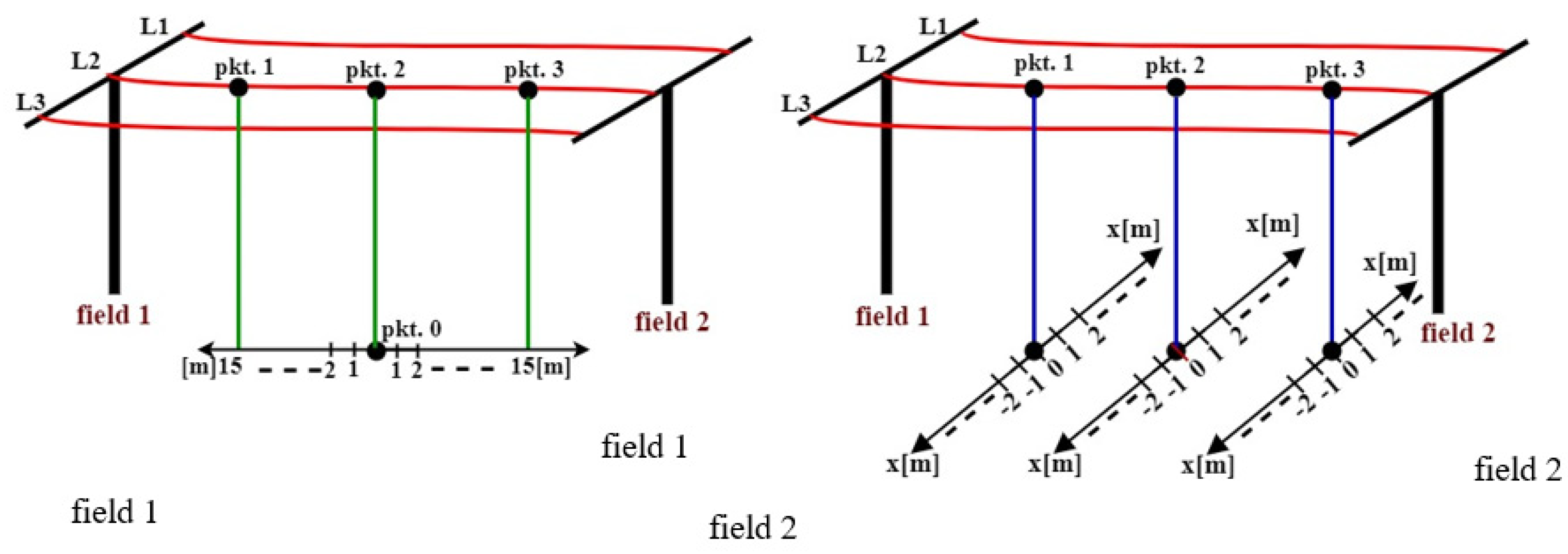
Studies involving the impact of unintentional electromagnetic field on the external and internal environment of a container housing telematics and security systems were conducted in accordance with
Figure 2.
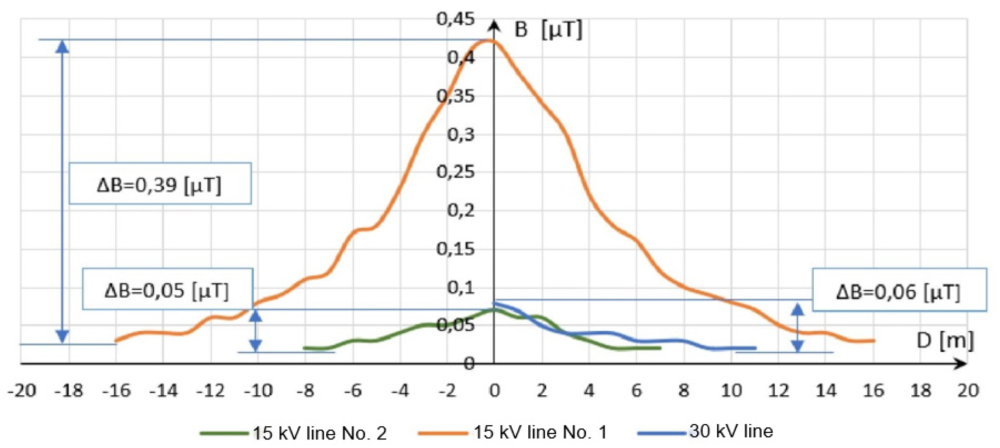
The presented characteristic curve (
Figure 3) shows a significant decline in magnetic field induction B with increased distance from the studied lines. Magnetic field induction B reaches a field background level at a distance of 17–19 m from point 0 in the case of the 15 kV power line No. 1, whereas, for the 15 kV power line No. 2 and the 30 kV line, this distance is 7–9 m from point 0, with the measurement conducted in accordance with
Figure 2. Disproportions between the maximum and minimum magnetic field induction B, depending on the measurement location, can be noticed when analyzing the resulting distribution. According to the Biot–Savart law, magnetic field induction B is proportional to the value of the flowing current and inversely proportional to the distance of the measuring point from the field source. Higher voltage of a transmission line supplying a container does not necessarily mean the presence of higher magnetic field induction B values. This is confirmed by the characteristic curves in
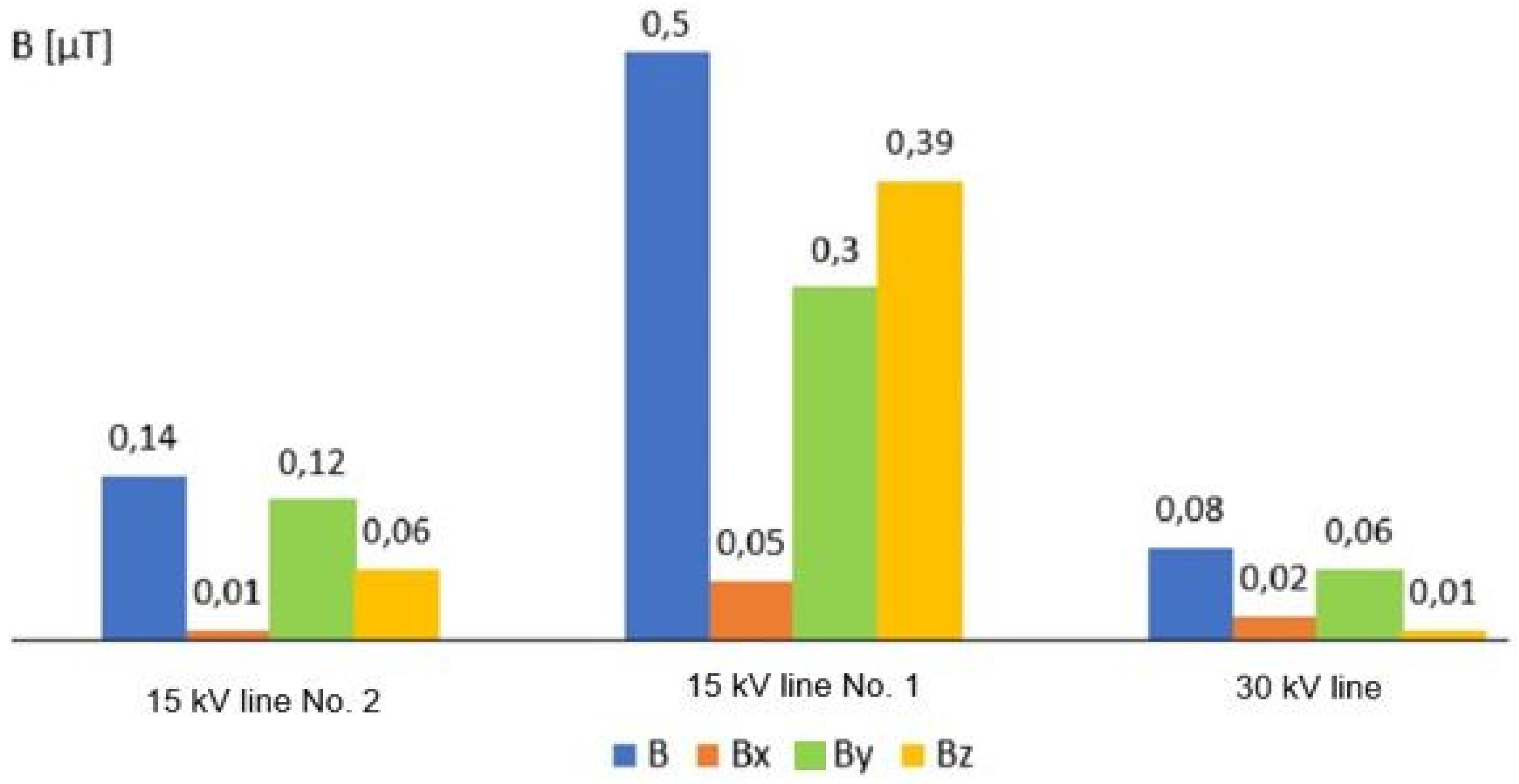
Figure 3. The values of magnetic field induction B components B
x, B
y, and B
z are shown in
Figure 4 for measuring point No. 2 (
Figure 2), due to the fact that it provided the highest magnetic field induction B values.
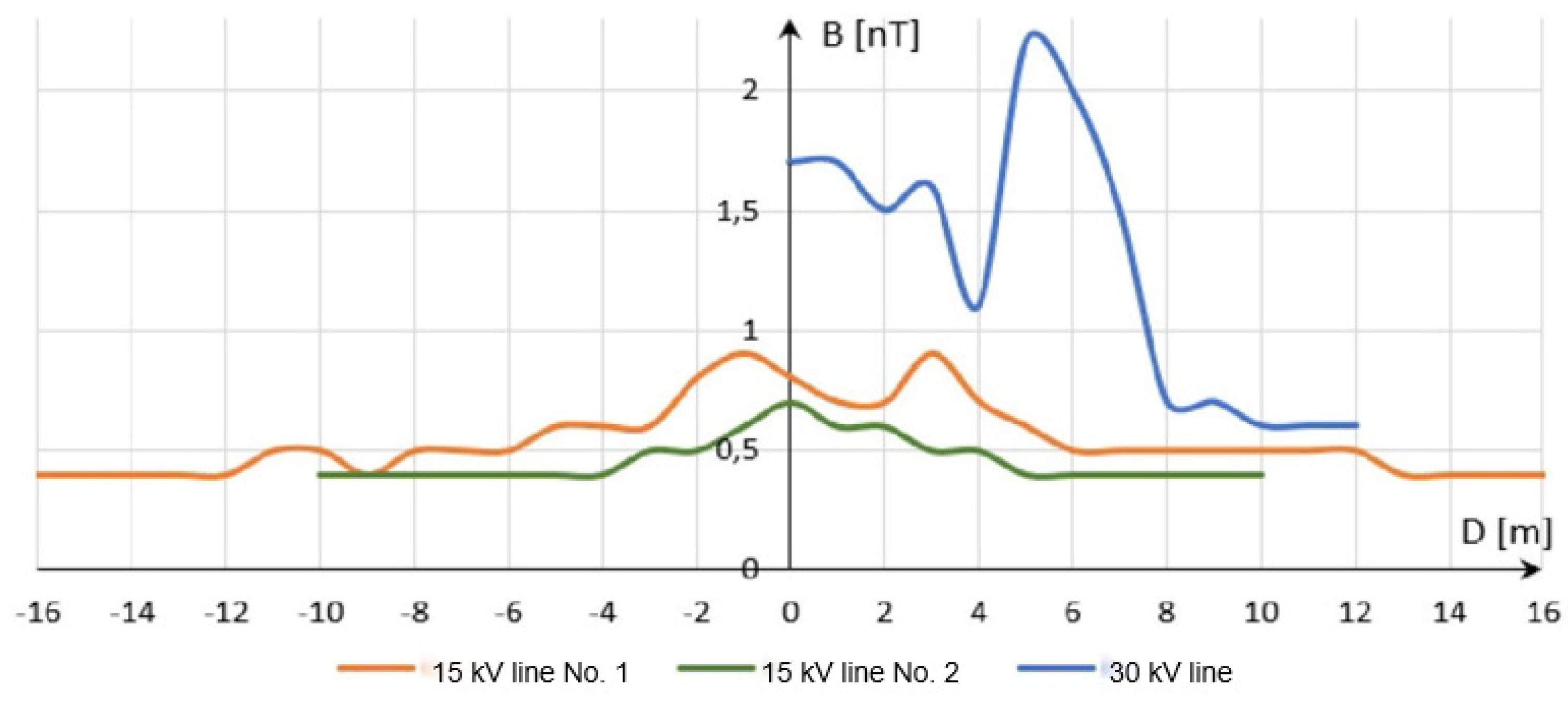
Magnetic induction in the VLF range was also measured at measuring point No. 2 (
Figure 2). The results are shown in
Figure 5.
The maximum magnetic field induction B for the VLF range under the 30 kV line was 2.2 nT, which was achieved at a distance of 5 m from point 0 (measurement in accordance to
Figure 2). In contrast, the maximum magnetic field induction B was 0.9 nT for 15 kV line No. 1 and 0.7 nT for 15 kV line No. 2.
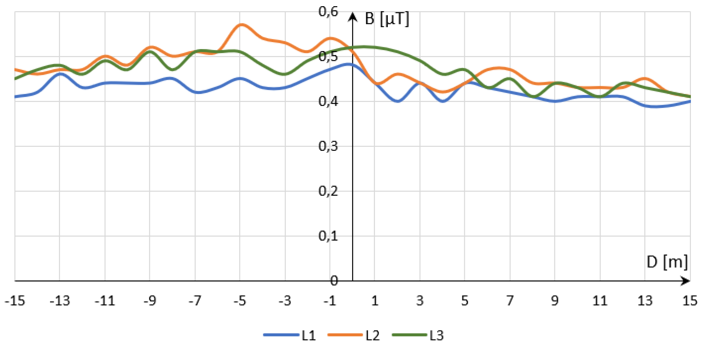
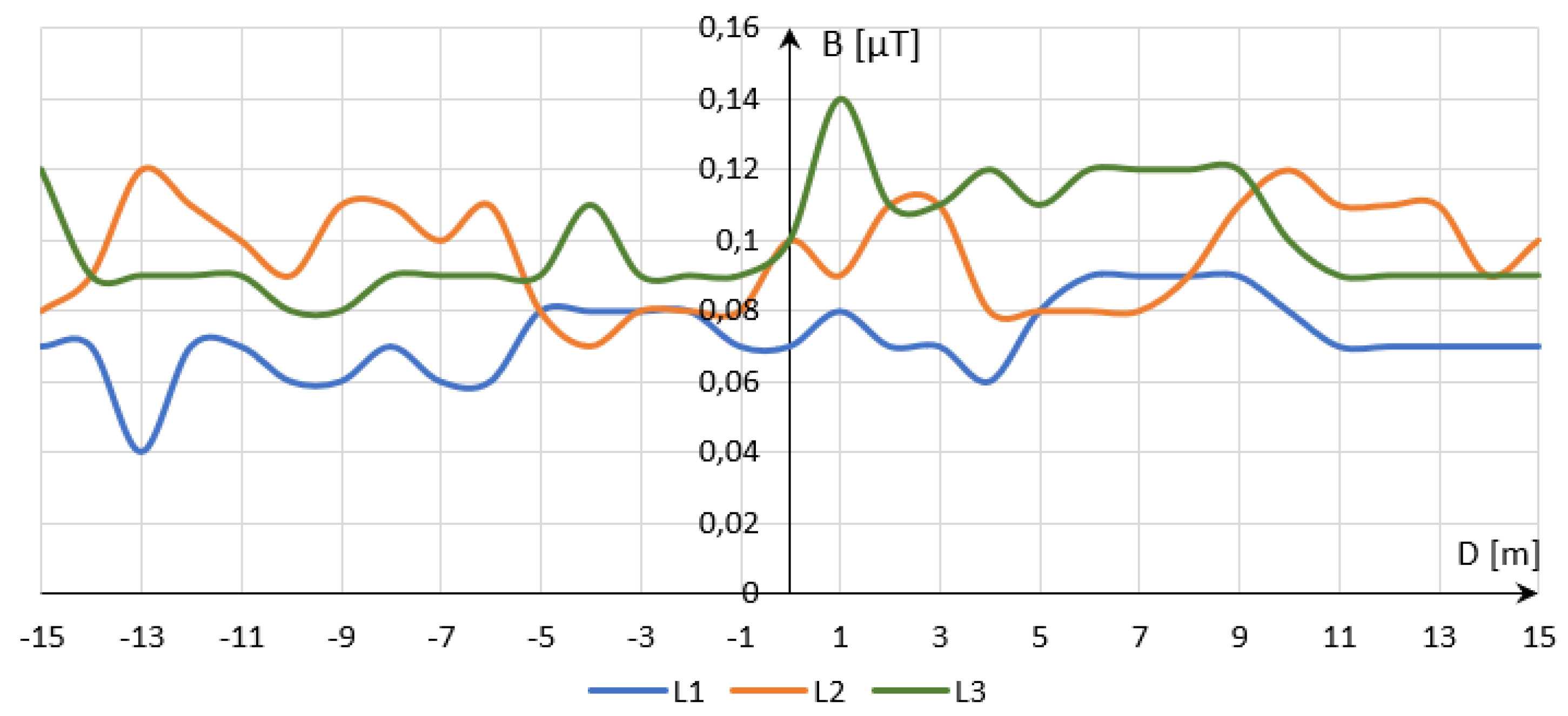
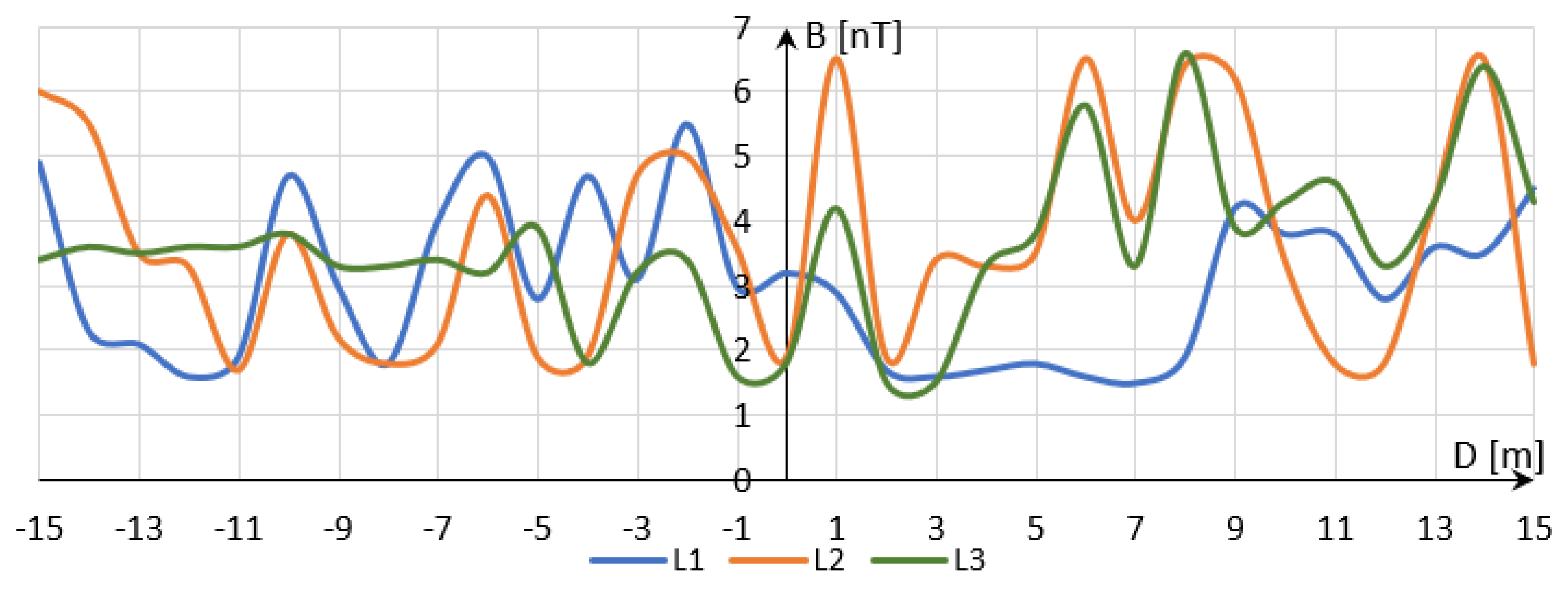
Figure 6 and
Figure 7 show the measurement of magnetic induction along phase conductors of the container supply lines for the ELF range and two supply voltages—15 and 30 kV. The measurement procedure is shown in
Figure 2.
The maximum magnetic field induction B measured along the phase conductors for the ELF range was identified under the central L2 conductor of the 15 kV line No. 1 and amounted to 0.57 μT, while the value under the 30 kV line was equal to 0.14 μT.
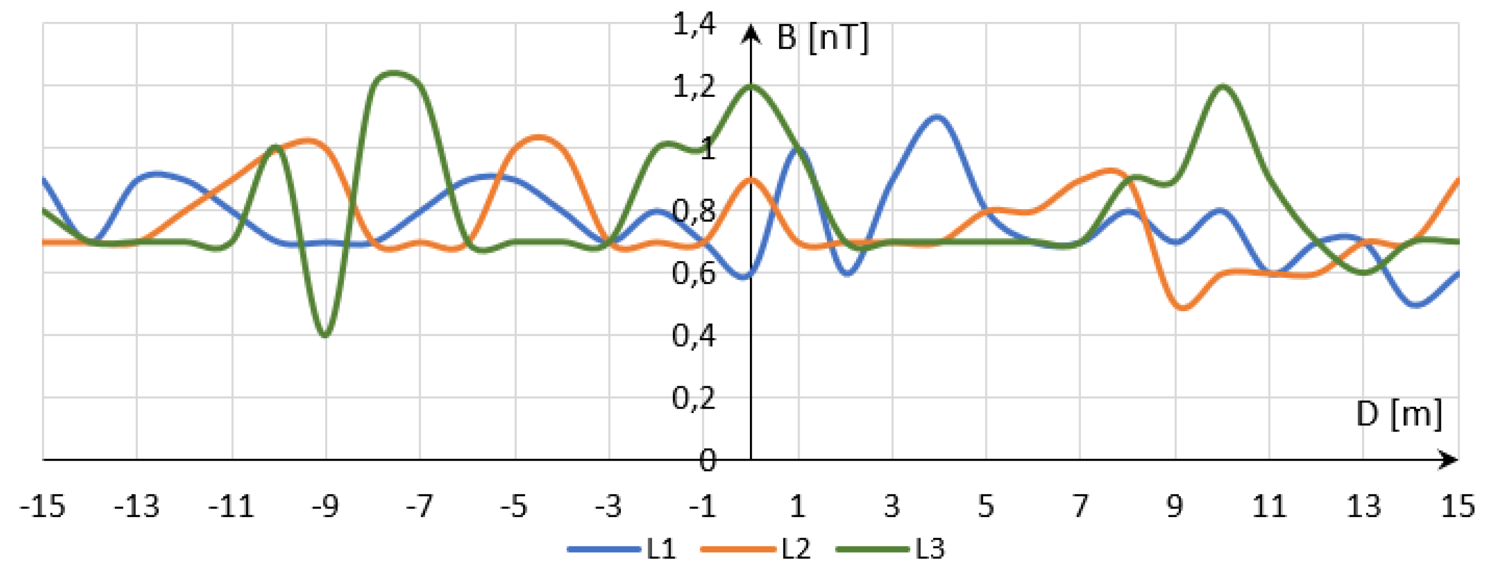
Figure 8 and
Figure 9 show the magnetic field induction B along phase conductors for the VLF phase (measurement methodology shown in
Figure 2). Upon observing the changes in the magnetic field induction B along the phase conductors over the VLF range, it can be noted that the 30 kV supplying the container was distinguished by higher values relative to both 15 kV lines. There were also significant differences between the maximum and minimum magnetic field induction B value depending on the rated voltage of the line supplying the container with telematics and security systems.
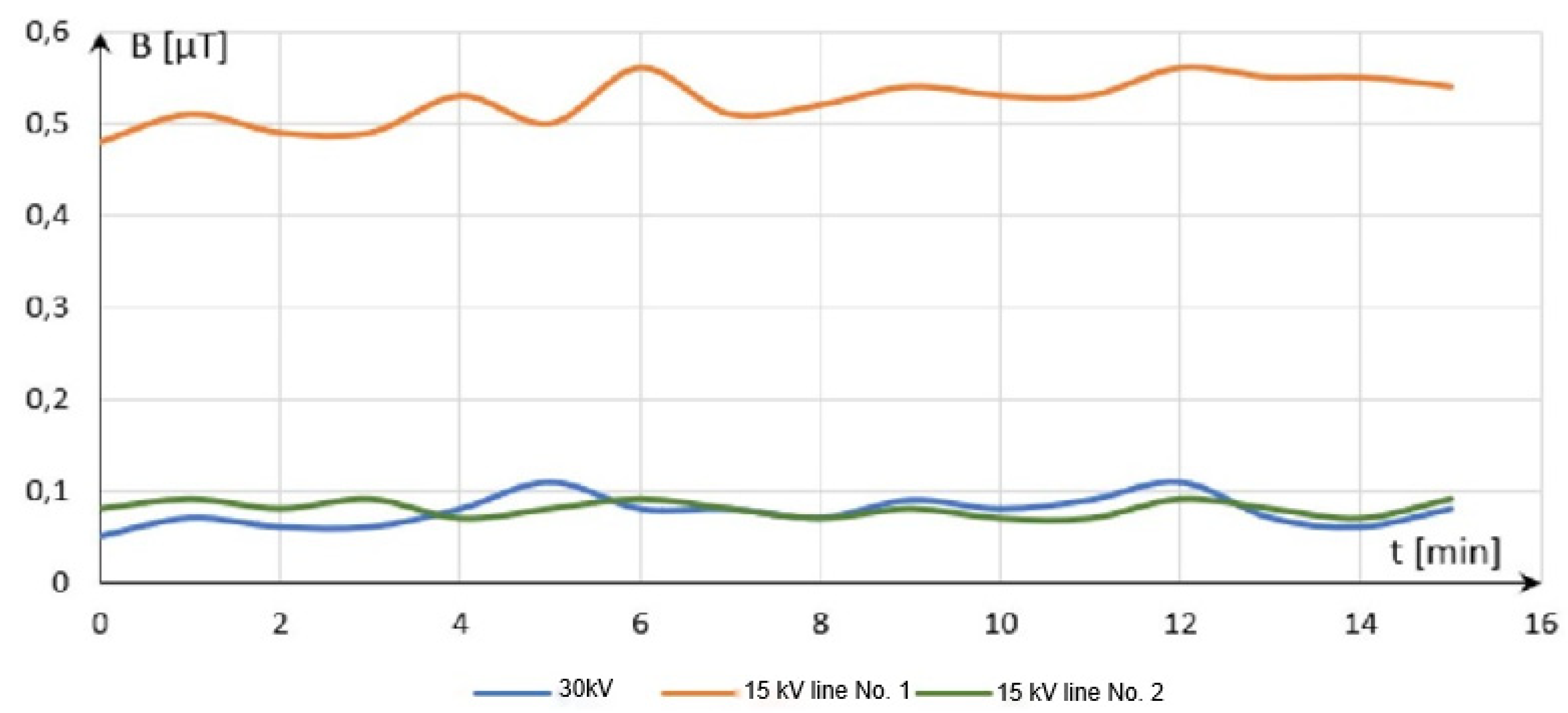
Changes in the magnetic field induction B over time were also measured. The measurements were taken in the location where the highest values were recorded. The magnetic field induction B value was read every minute for 15 min. Measurement results are shown in
Figure 10. On comparing the magnetic field induction B values obtained over time, it can be concluded that they remained on average at a constant level. It was 0.53 μT for the 15 kV line No. 1 and 0.08 μT for the 30 kV and 15 kV No. 2 lines.
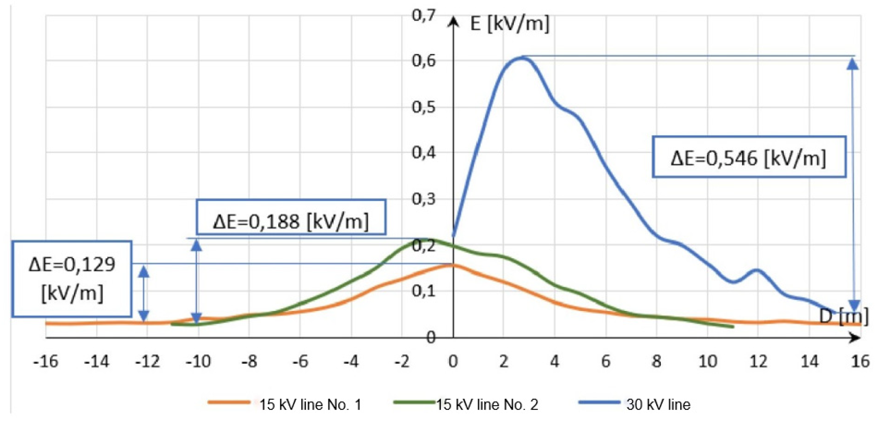
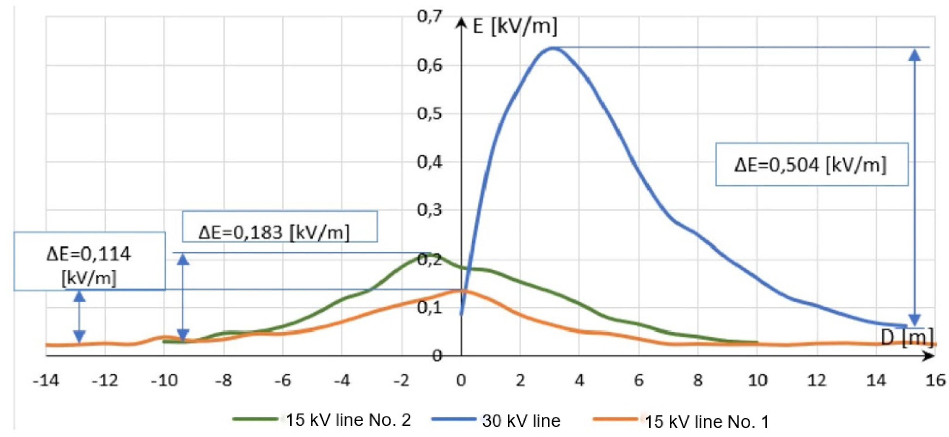
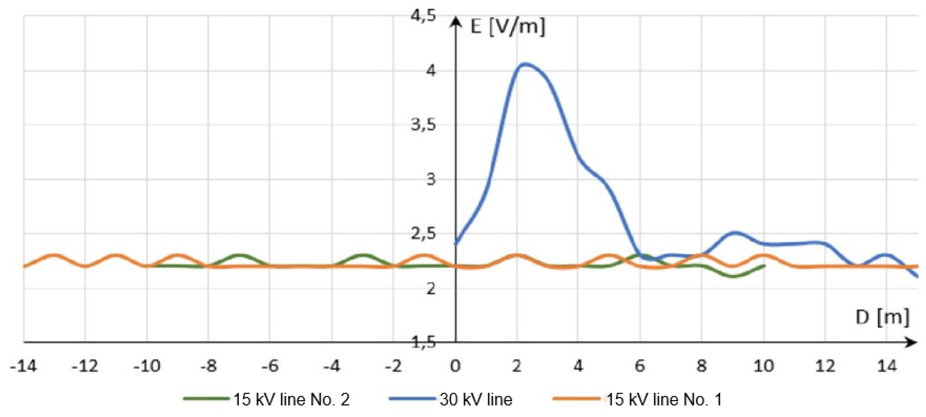
Figure 11 and
Figure 12 show the distribution of electric field strength E across MV power lines supplying the container with transport telematics system and ESS, at two measuring points, in accordance with
Figure 2.
Electric field strength E decreased with increasing distance from point 0 and reached a background value at a distance of 11–13 m for the 15 kV power line and 15–16 m for the 30 kV line. As in the case of the magnetic field induction B, the electric field strength E also reached the highest values at measuring point No. 2. The 30 kV power line, however, achieved significantly higher electric field strength E values. Along with the increase of the line voltage, the electric field strength E also increased.
The electric field strength E was also measured in terms of the VLF range for measuring point No. 2 (measurement methodology as in
Figure 2). Measurement results are shown in
Figure 13.
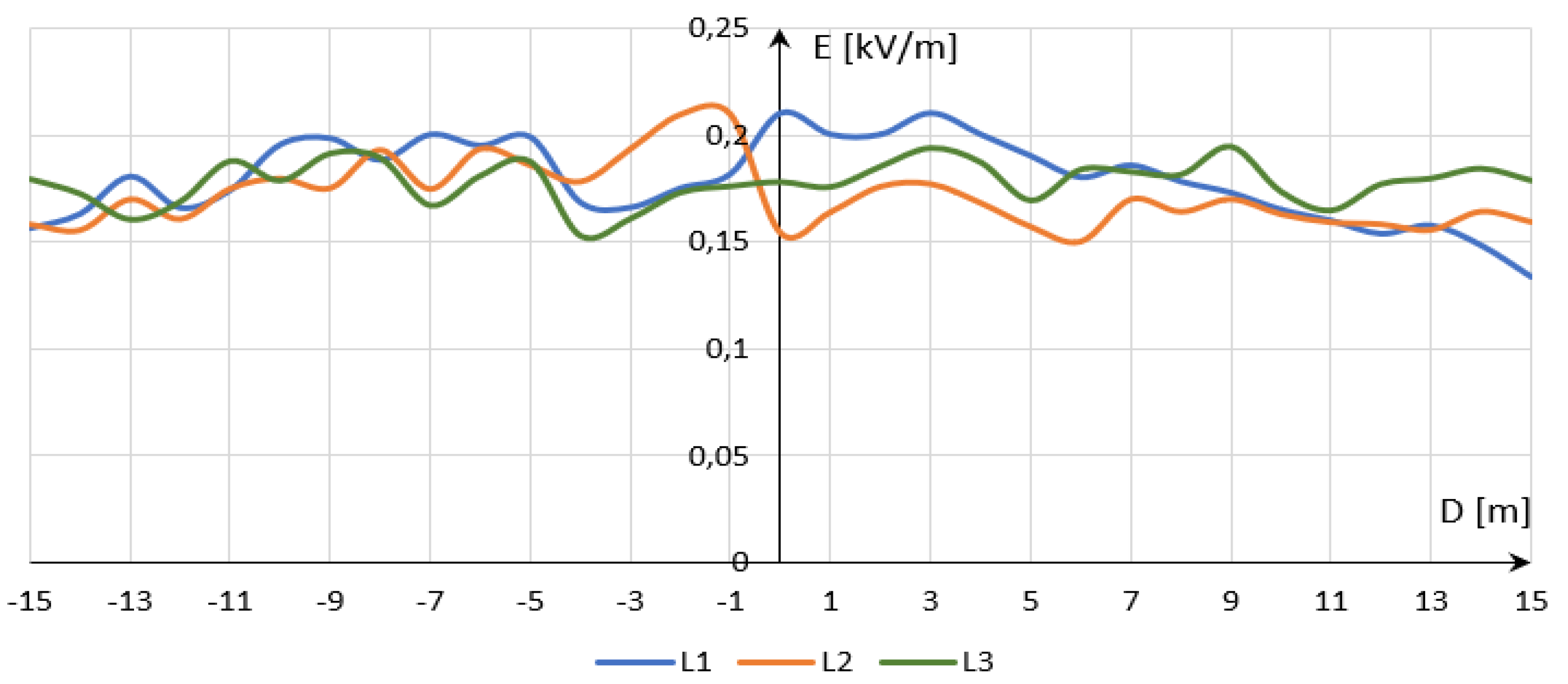
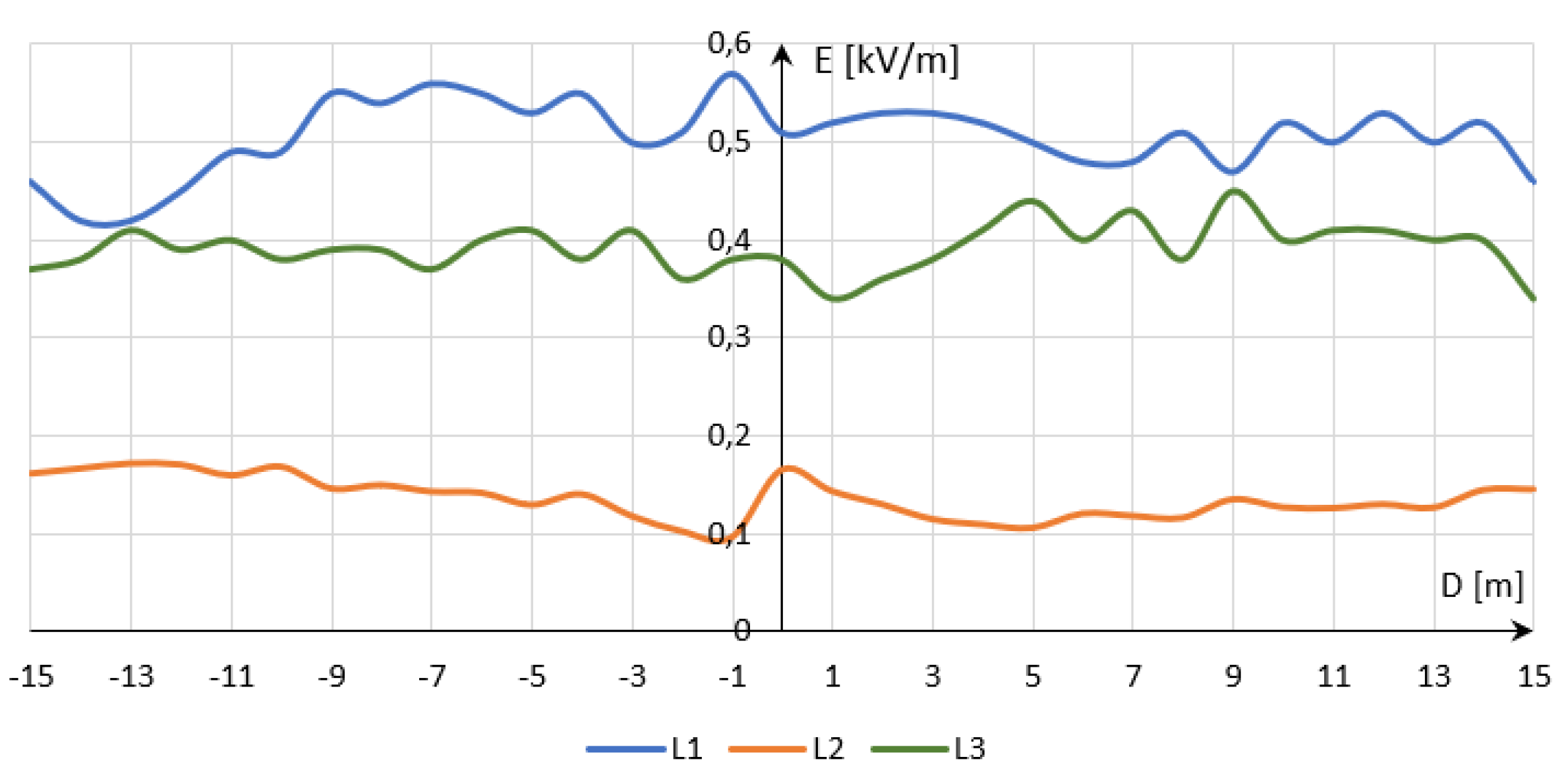
In the course of analyzing the characteristic curves, it can be concluded that 15 kV lines produced virtually no electric field strength E component over the VLF range. The changes in the values over the entire measuring range fluctuated from 2.1 to 2.3 V/m, which corresponded to the values of the measured electric field background. The changes in the electric field strength E along the phase conductors of container-supplying MV power lines were also analyzed. The results of these tests are shown in
Figure 14 and
Figure 15.
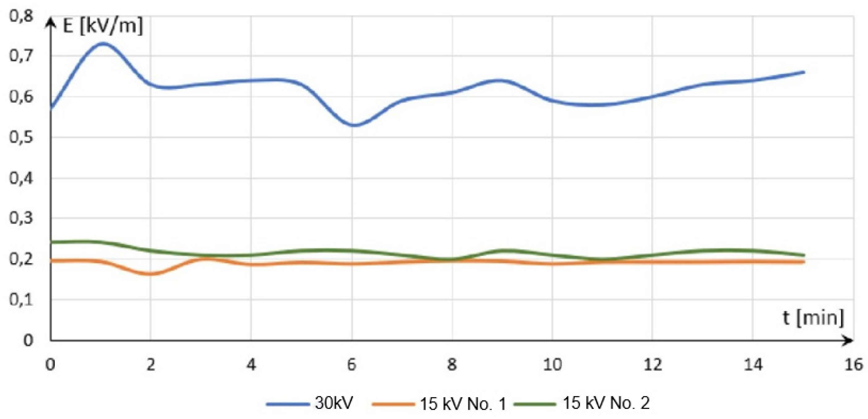
Figure 16 shows changes in the electric field strength E under MV lines supplying the container, for the ELF range. In the case of both 15 kV lines, the electric field strength could be considered constant, and its mean value was 0.19 kV/m and 0.21 kV/m for 15 kV lines No. 1 and No. 2, respectively. In the case of the 30 kV line, the electric field strength ranged from 0.53 kV/m to 0.73 kV/m.
When analyzing the obtained measurement results for all power lines supplying the container, it can be concluded that the highest magnetic field induction B was recorded under the 15 kV line No. 1 and amounted to 0.57 μT. In contrast, the maximum electric field strength E component value was at a level 0.64 kV/m, which was achieved near the 30 kV line.
3. Metal Container Housing: Determining the Shielding Effectiveness for a Low-Frequency Electromagnetic Field
When constructing and operating electronic, transport telematics, or security equipment and systems, it is required to protect a given technical facility against the impact of undesirable electromagnetic interference over a wide spectrum range [
24,
25]. Appropriately manufactured guards, usually metallic, called shields are used in such cases in accordance with the electromagnetic compatibility pyramid [
26,
27,
28]. An electromagnetic shield is always a conductive shield that separates two areas. One is the source, e.g., of an unintentional electromagnetic field, i.e., MV power lines supplying the container in this case. The other does not contain the source, i.e., it is the container interior. This separation applies not only to fields, but also to fault currents. A shield also provides a potential reference for cables routed from the container housing and for electronic circuits located inside the metal container. The most important parameter that characterizes shielding execution is the so-called “shield effectiveness S coefficient”. It is a ratio of the shield attenuation determined on the basis of field residual strength (electric, magnetic, or electromagnetic field) measured in the presence of a shield and the field strength measured without the shield. The shielding effectiveness S coefficient is a dimensionless value. Shield attenuation S is most usually expressed in dB, as per Equation (1).
where
Pbe is the unshielded field strength, and
Pze is the shielded field strength.
Shield attenuation is defined in relation to an electrical (Equation (2)), magnetic (Equation (3)), or coupled field. Shield effectiveness relative to the electrical or magnetic field is expressed by Equations (2) and (3), respectively.
where
Ebe, Hbe are, respectively, unshielded electric and magnetic strengths, and
Eze,
Hze are, respectively, shielded electric and magnetic strengths.
A positive attenuation values is expressed in
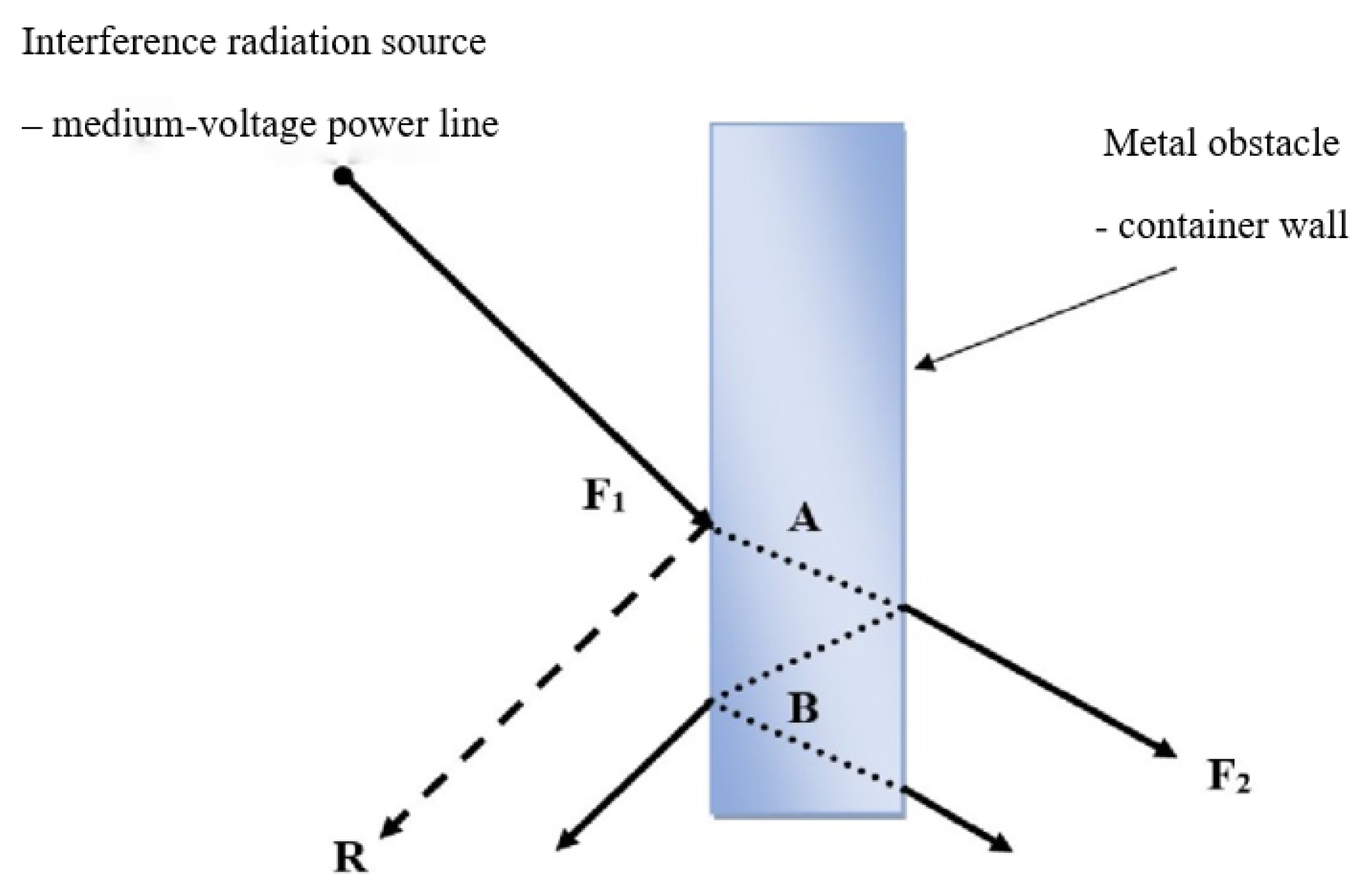
dB and means a reduction in field strength. A negative attenuation implies a strength increase. In any given electronic device, at various frequency ranges, poorly executed shielding may behave like a directional antenna. Shielding effectiveness is a function with numerous variables and depends on parameters such as frequency, shield geometric structure, location within the shield where the field is determined, type of shielded field—electric, magnetic, or electromagnetic, incidence direction, and wave polarization. The total shielding effectiveness of the material used to manufacture the container where the telematics and security systems are operated is equal to the total relative measures of attenuation losses
A, deflection losses
R, and the correction factor
B. The correction factor
B takes into account the so-called “numerous deflections in thin shields” (
Figure 17). In such a case, the total shielding effectiveness of a metal container can be expressed using Equation (4).
The following materials are sufficient for the shielding of the low-frequency electromagnetic fields that are generated by MV power lines:
thin, highly conductive materials, 20 to 50 µm thick, since they guarantee high losses related to deflection of electric waves;
several millimeter thick materials, when shielding a magnetic field. This is brought about by the poor attenuation that is associated with waves deflecting from the shield surface; hence, it must provide high absorption losses if the shield is to be effective (shielding fields with a frequency up to 500 kHz requires the application of a magnetically soft material, e.g., iron with relatively conductivity μr = 200 or Alu-metal with a thickness >0.5 mm).
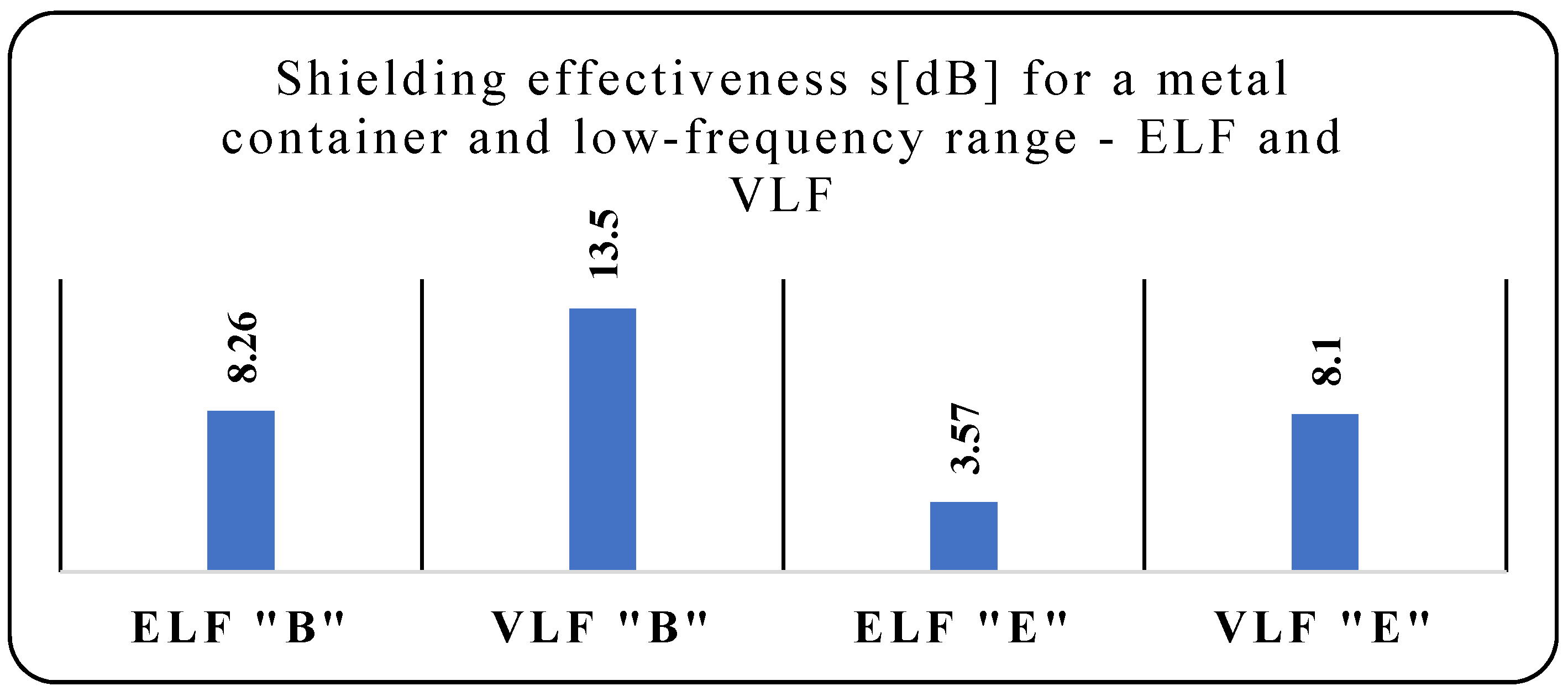
The simplest way to reduce the impact of an electromagnetic radiation source on a given electronic device or element is placing it as far from the source as possible—in this case, away from the medium-voltage supply lines. This will enable locating it in areas where the unintentionally generated electromagnetic field exhibits low values. However, it is impossible to always apply this principle. In such a case, a solution is to mitigate the impact of an electromagnetic field by shielding the source or a selected space around the MV power lines. Shield effectiveness was measured for a metal housing of a container made of sheet metal with thickness h = 1.5 mm. The results of shielding effectiveness measurements for the ELF and VLF ranges are shown in
Table 2.
Figure 18 shows the shielding effectiveness of a 1.5 mm thick steel material for magnetic field induction B and electric field strength E over the ELF and VLF ranges. The shielding effectiveness value should be taken into account when determining operating process safety indices for security and telematics systems operated inside any metal container.
4. Analysis of the Security System Operating Process in Terms of the Impact of Unintentionally Generated Electromagnetic Interference
The impact of use [
29], operation and power supply [
30,
31] conditions, including the impact of unfavorable external [
32,
33,
34,
35], and internal [
36] environmental factors (e.g., low-frequency electromagnetic field) on electronic telematics [
37,
38,
39,
40] and security systems can be described through, e.g., a change in the intensity of damage to λ components making up a specific system [
41,
42]. Telematics and security systems and equipment operated in the container contain a large number of active and passive elements. These elements exhibit various margins of resistance to different interference, e.g., electromagnetic, environmental, electrical, thermal, and mechanical, generated in a container in an intentional or unintentional manner. The resistance value undergoes constant change impacted by various environmental factors, e.g., electromagnetic interference, temperature, humidity, and precipitation. Therefore, it is essential to develop an operating process model that takes into account the resistance to electromagnetic interference.
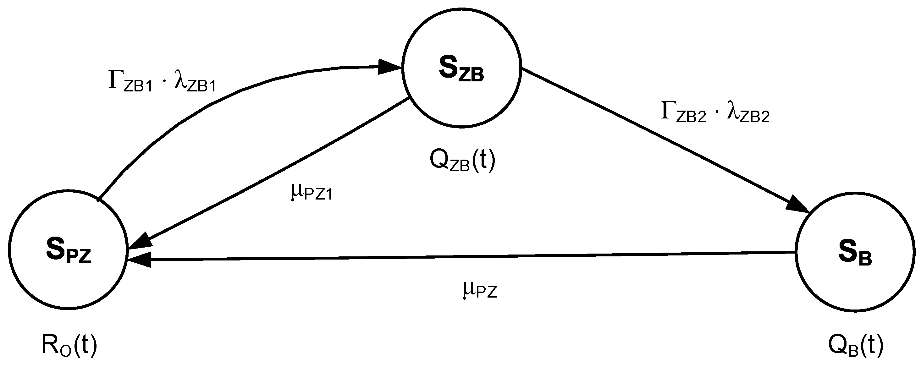
A functional analysis of an electronic security system located in a metal container, taking into account the impact of unintentionally generated electromagnetic interference, enables illustrating the relations therein from the reliability and operational perspective, as demonstrated in
Figure 19.
The state of full fitness SPZ is a state in which an electronic security system operates correctly. The state of security hazard SZB is a state in which an ESS operates partially correctly. The state of security unreliability (failure) SB is a state in which an ESS does not operate correctly.
In the event of the ESS staying in a state of full fitness SPZ and the presence of unintentionally generated electromagnetic interference resulting in the inability to perform certain function, the system will shift to a state of security hazard SZB, with an intensity equal to the product of ΓZB1 λZB1.
An ESS in a state of security hazard SZB can move to a state of full fitness SPZ, if the ability to implement all ESS functions is restored, or security unreliability QB, with an intensity equal to the product of ΓZB2 λZB2 in the event of electromagnetic interference, resulting in ESS’s inability to perform its functions.
Transition from a state of security unreliability SB to a state of full fitness SPZ takes place when the ability to perform all ESS functions is restored.
The ΓZB1 and ΓZB2 coefficients quantify the impact of unintentionally generated electromagnetic interference, taking into account the applied countermeasures.
The electronic security system presented in
Figure 19 is described by the following Kolmogorov–Chapman system of equations:
If we assume the following baseline conditions for further analysis:
and then apply the Laplace transform [
43,
44,
45], we obtain the following set of linear equations:
After further conversions, we acquire the symbolic (Laplace) probabilities for the ESS to stay in functional states.
The determined relationships in Equation (8) enable calculating the probabilities of an electronic security system staying in the three distinguished states, taking into account the impact of unintentionally generated electromagnetic interference. The introduction of the ΓZB1 and ΓZB2 coefficients of electromagnetic interference in terms of impact on the ESS enables to rationally select solutions aimed at protecting against electromagnetic interference.
5. Conclusions
The issue of operating transport telematics and electronic security systems located within railway areas is extremely important. They ensure the safety of both vehicles and passengers. For this reason, the issue related to the impact of unintentionally generated electromagnetic interference on the ESS becomes one of particular importance. They can lead to a state of partial fitness of transport telematic systems and electronic security systems, whereby the ESS is unable to execute all of its functions.
In order to determine the impact of unintentionally generated electromagnetic interference on ESS, the authors measured the low-frequency electromagnetic field generated by MV—15 and 30 kV—power lines. The obtained results enable determining numerous characteristic curves that allowed defining points of particularly high magnetic and electric field strength values. An analysis of the solution in the form of a metal housing for a container containing transport telematics and electronic security system equipment was also conducted. It was found that such a structure reduced the impact of electromagnetic interference originating from medium-voltage power lines on the analyzed systems. Therefore, it is possible to increase shielding effectiveness for a low-frequency electromagnetic field.
The conducted security system operating process analysis in terms of the impact of unintentionally generated electromagnetic interference enabled determining mathematical relationships defining the probabilities for a system to stay in distinguished states. It also allowed numerically defining the impact of applied solutions aimed at protecting against electromagnetic interference. Therefore, it is possible to rationally select solutions (structural and organizational [
46]) aimed at protecting systems against electromagnetic interference.
The next stage of the study was to develop an ESS operating process model that takes into account the impact of unintentionally generated electromagnetic interference. Introducing the electromagnetic interference impact coefficient enables a rational selection of solutions aimed at protecting against electromagnetic interference. This is a significant practical aspect of the conducted test and scientific studies discussed in this article, since it has application value. As further research, the authors are planning to determine the values of electromagnetic interference impact coefficients depending on the applied design solutions.


