1. Introduction
In the modern industry there is a high level of competition between various technical solutions of similar tasks and initial processes. After inventing a solution to the problem, it is necessary to optimise the time, parameters, required for production dimensions, and flow of the process; to prove to the customer the durability of the solution and compatibility with ready-made solutions; and minimise the cost of mass production. Even with a solution better than the competitors, especially during processes that are intolerable to time and require high-reactive systems, the weak side of this solution may be insufficient minimisation of production dimensions and energy consumption, and overheating in extreme situations; therefore, the need for high power cooling systems and as a consequence of that, excessively harmful effects of production processes on the environment.
In a previous publication [
1], one example of a highly reactive system operating on parallel piezoelectric kinematics for drilling non-circular holes was presented. This process combines three dynamics: an electronic system, a reaction piezoelectric system, and a mechanical system with a workpiece. The additional complications are the need to use high-dimensional mechanical systems with complex prediction of mechanical resonances and intolerance of the manufacturer on drilling time (up to 30 s per 5 cylinders of an internal combustion engine with the high of 150 mm with the possibility of non-circular holes with up to 75 different shapes per each cylinder). The operation of this system requires the coordinated operation of several different dynamics and synchronous intelligent control at high frequencies, which during the overheating of the machine components becomes unpredictable. This makes this system a good example to consider this topic.
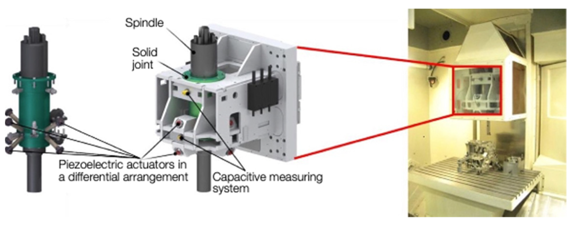
The system operates on the principle of a parallel kinematics using eight piezoelectric actuators (
Figure 1). The advantage of the selected system results from the parallel kinematic arrangement with eight actuators. For simplified considerations, it is possible to initially only use individual degrees of movement freedom and the coupled degrees of processing freedom. This means that the results of the research can be transferred not only to the simple single-axis systems, but can also be used for very complex systems with several degrees of freedom and couplings [
1].
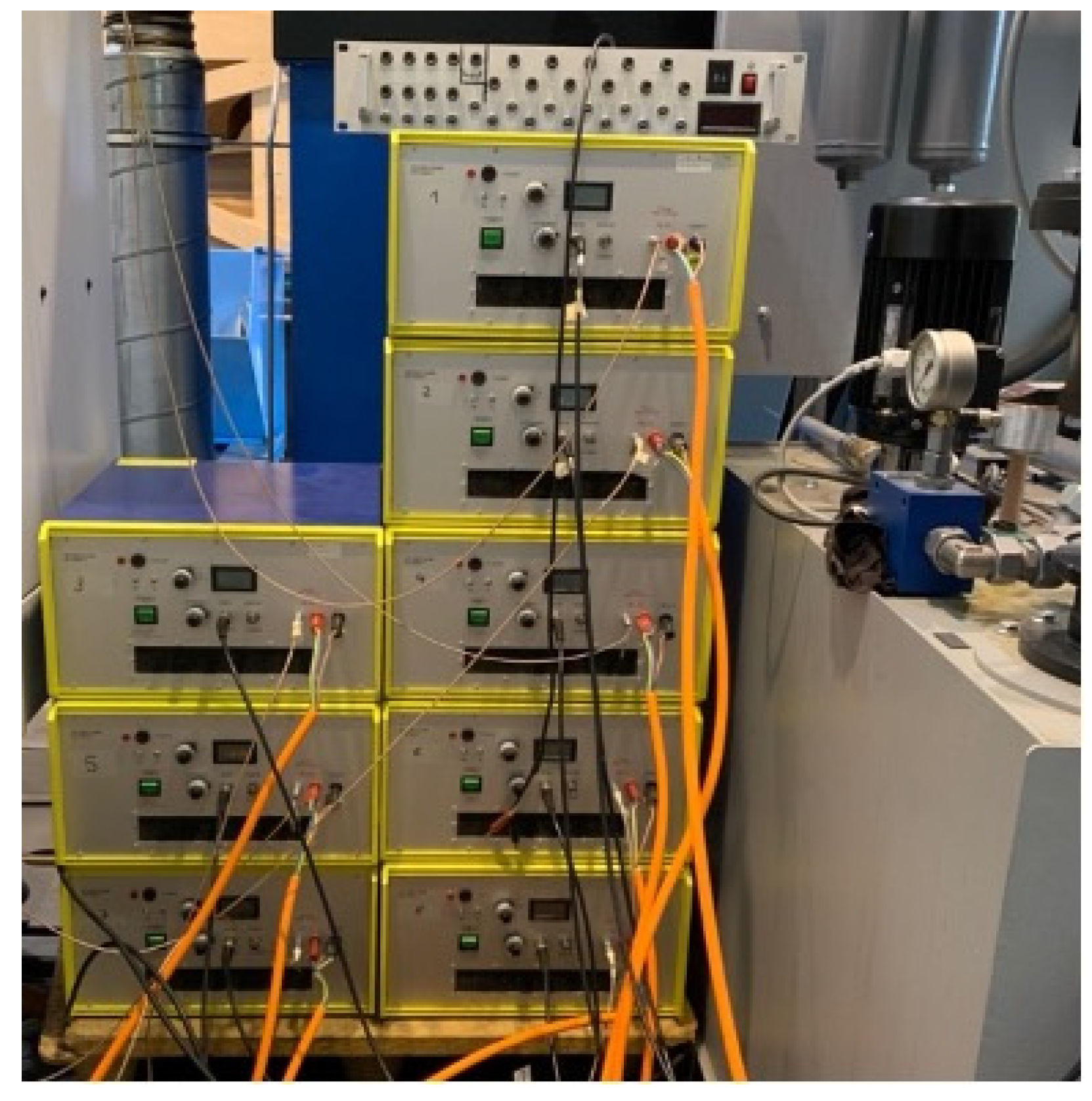
Regardless of the power supply and cooling system of the machine (rotary motor with oil cooling, motor in Z-direction, active sensors, protective- and door motors), it is also necessary to use a generator with eight amplifiers up to 1000 Volts each for each piezoelectric actuator with capacitors connected in parallel from 0.3 to 4 µF, depending on the operating mode (
Figure 2).
This structure has a large number of problems that affect not only the quality of automatic operation and quality of manual work of the staff, but also the need for multiple repetitions of the drilling process, increased cooling device requirements, and a large environmental footprint on an industrial scale. The system requires significant synchronisation between itself and the encoder of the machine rotor. Any changes in operating modes can destabilise the entire system. Heat is also a major problem. During the calculations of the dynamics modes and its stabilisation, it is difficult to consider the heating of the actuators, as a result of which the rattling of piezoelectric actuators appears even in static modes of operation, which can also be clearly heard, due to the loudness of the high-frequency rattling. During the low frequency drilling signal or low order shapes processing, overheating of amplifiers is observed and even melting of the insulation of the inductors after 15 min processing time can be seen, what is a substantial problem for the system.
The task of designing a control system will be considered completed and can be used in the further research for another device if it will prove the elimination of the limitations of the control system, preventing unwanted resonances due to changes in the operating mode or Z-position of the spindle with the future study and laying of a base for projects on optimising the thermal processes of the electronics and piezo electronics of this machine and industry machines in general, thereby making it more competitive in the industry and environmentally friendly
2. State of Research
The problem of control, optimisation of cooling systems and the need to apply carbon footprint reduction techniques in the industry by using optimised control for devices and machining tools is shown on the example of research of a parallel kinematics system used for shape drilling. The relevance of the application of piezo kinematics for highly reactive systems to increase production limits is described in many publications and scientific works [
2]. In a previous publication [
1], examples of the use of piezo actuators both in ultrasound technology [
3] and in rotary machines [
4], were touched upon. The advantages of using piezo electric actuators for ultrasound-assisted machining and FTS-systems were also shown [
4,
5,
6]. However, in the field of machine tools, piezo kinematics, as optimisation of its control, have not yet obtained an established niche. Since piezo kinematics is not in an ideal environment, but is used for micromovements of a bulky spindle that rotates and has its own mechanical resonances with a whole machine (as in the case of the machine described above), there are coming restrictions limiting the control system or making it unpredictable under many conditions [
7,
8], or the control range is highly dependable on the control algorithm [
9,
10].
During previous projects, the piezoelectric actuator systems for machine tools have been developed followed by an in-depth analysis of the possibilities of their optimisation.
Many methods have been proposed for solving the problem of controlling piezo kinematics in various directions of industry: systems for vibration compensation and increased dynamics in the power train [
11], operation of two active systems with a spindle [
7,
12], an active honing tool [
13] and a piezoelectric cross table [
13] for the fine positioning of the cutting edge or workpiece. Moreover, the use of PI controllers and compensation controllers for the production of typical cloverleaf geometries have been investigated [
14] but there remains problems of optimal control, overheating, excess amplitudes due to resonances, and distortion of the trajectory shape of the cutting edge movement.
3. Models of System Build and Control
In a previous publication [
1], a model for simplifying the control of a non-circular drilling machine with a shape control system on the parallel kinematics was performed. All previous versions of control systems [
11,
12,
13,
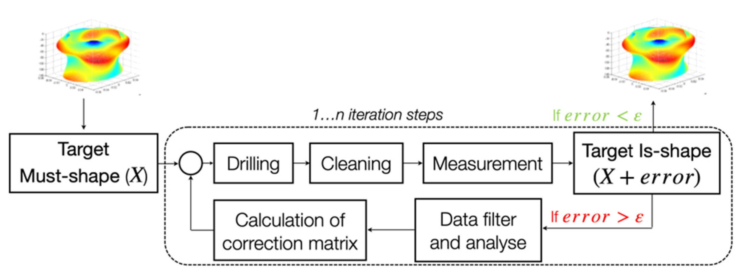
14] have not been able to control all processes and modes of operation of this system fully due to the complex dynamics of the electronic system with piezoelectric kinematics and large-sized inert mechanical system. In the previous project, after several experiments with existing control systems and having problems with the control going beyond the control bandwidth, the ILC (iterative learning control) method was decided on [
15,
16]. Due to the partial control, the processing continues in order to cut less material than necessary, so that in case of an error, this process could be repeated again on the same workpiece with applied corrections (
Figure 3). In practice, this process could take 50, 70 or sometimes even more iterations. For better problem understanding, on a working day with a medium workflow load, only the measurement results of the 5-cylinder unit will be available at best the next working day.
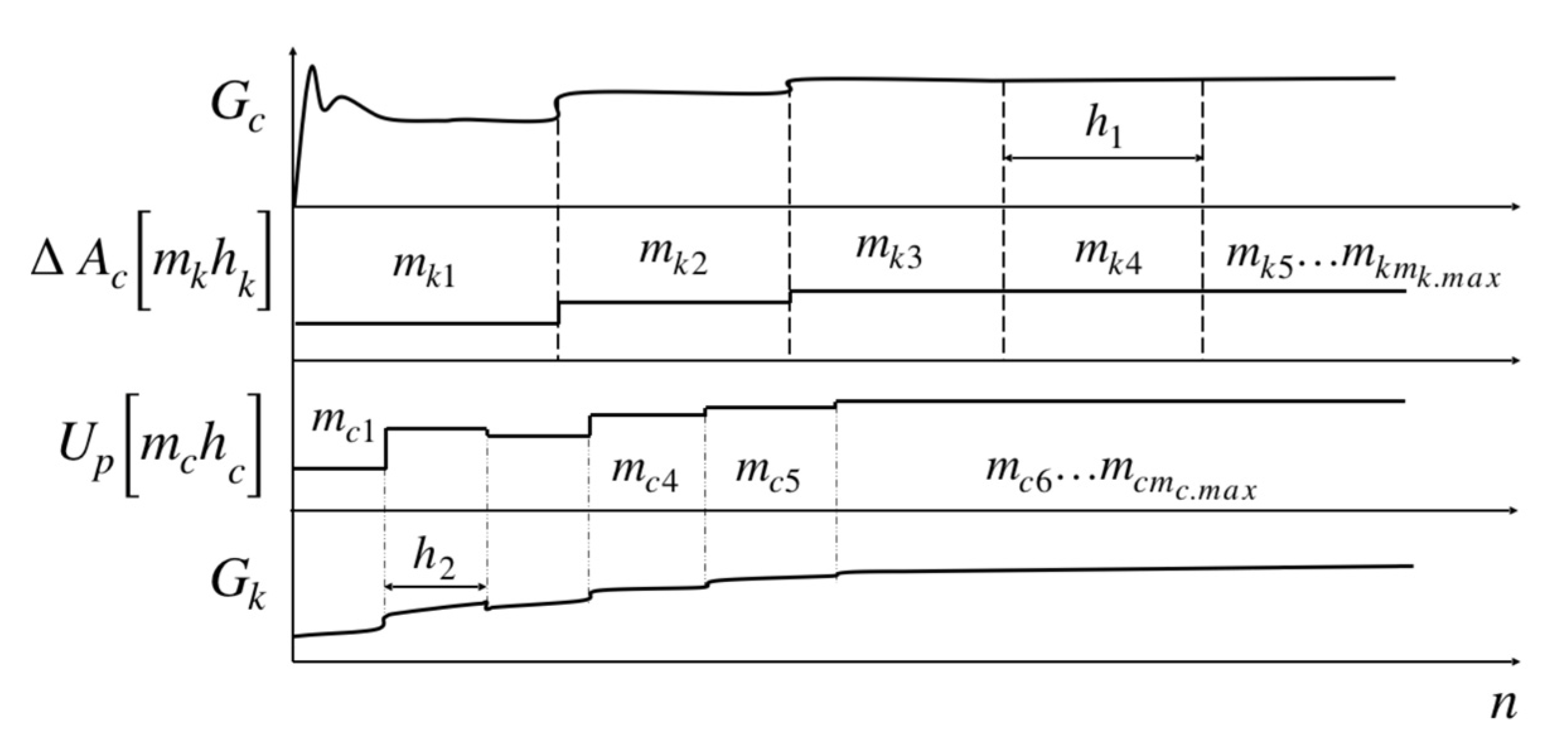
Building a model of the system state with a diacoptics section on the different processes and dynamics speed allowed to separate the processes that can be easily controlled and the processes for which it is necessary to conduct iterative control [
1,
17,
18]. This allowed to build a stable control system for piezoelectric actuators with capacitive sensors feedback and combine it with the machine learning module. The purpose of this construction is to reduce the required number of iterative steps to a minimum for workpieces with similar characteristics during reprocessing under different machine conditions and external influences. Ideally, the trained model accepts the input of the rotary motor encoder and capacitive sensors without load to predict the data about the machine state and external influences and adjusts the control instantly during the process. Under identical conditions, it is also possible to work without capacitive sensors at all.
This section allows soft switching between different control systems, control methods, and reaction rates.
The most difficult for calculation and prediction operation mode is non-stationary mode due to a change in the processes state with different reaction rates of the processes. For example, thermal and electromagnetic processes during the transient process that depend on each other, when the speed difference between electromagnetic and thermal processes is very noticeable due to the thermal capacity of the components. To determine the state of the system at a particular moment, the equation of system state is used in the basic form:
where
is the state of the system as a vector of current, voltage, temperature, strength and speed of the piezoelectric actuator, etc.
is a matrix of components (or transfer matrix) of the system, which characterises the electrical, mechanical, thermal characteristics of the system. Under ideal conditions, the matrix of coefficients is a constant because it characterises the parameters of the components (resistance of semiconductor elements and resistors, capacitance, inductance, etc.). In this case, the parameters of the components change over time depending on the temperature or as a reaction of one component to another. This complicates the further integration and makes the behaviour of the feedback control system unpredictable. One example is the experiment, during which the overheated piezoelectric element changes the impedance properties and capacitance in few times (in some experiments there was a maximum change in the parameters of the components even 5 times). Changing the parameters of the components affects the current flowing in these components, and unpredictable changing the current through the components again affects the heating also in unpredictable way.
is an external influence vector, which includes the power supply of the system, as well as parasitic thermal influences on the system and the energy generation by piezoelectric actuators and mechanics. It is obvious that the system with 3 dynamics is considered in this research, but also with thermal influence it will be already 4 dynamics, which have different speeds of the operating point movement, will be quite cumbersome and the integration methods will be unstable. In [
1,
18] methods and calculations of such systems were already presented with the subsequent transformation of the system state equation into a system of equations with constraint equations; discretisation of these equations; calculation of the integrating methods stability diacoptically [
17] separated equations and simplification of the general calculation model with an increase in the accuracy of the control of the system.
The result looks like a system of equations:
where
characterise the instantaneous state of systems with a different dynamics speed,
is reverse power transmitted from the dynamics of the load to the dynamics of control both in the case of generation (for example, from a piezoelectric actuator to an amplifier) and in the case of parasitic influences (the effect of heating on the system operation).
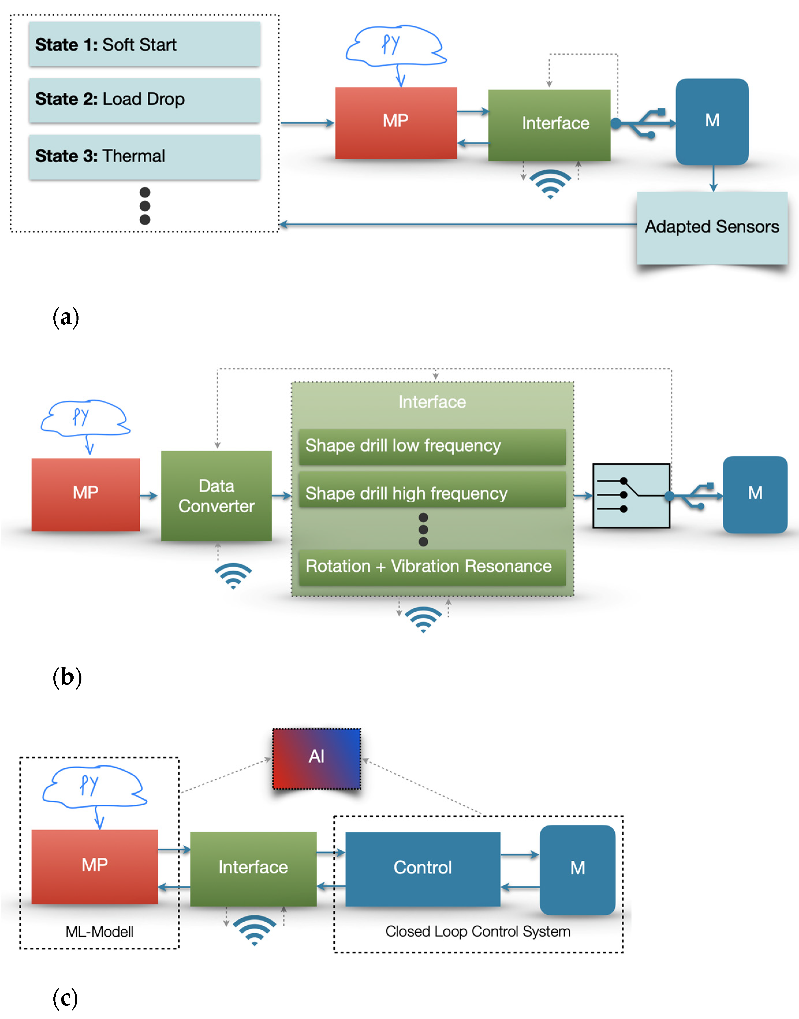
After choosing a discretisation step that satisfies the sufficient integration method stability requirements, further control system design is carried out in 3 ways, depending on the machine operating mode.
- 1.
Classic control system with fast seamless switching between suitable control systems (
Figure 4a).
- 2.
A discrete system that does not require integration and works on the segments of the state of the currently secondary dynamics in order to control the currently main dynamics (
Figure 4b)
- 3.
Unification of all dynamics into one equivalent dynamics with further process separation by speed. Speeds that go beyond control are processed by the machine learning module (in this research, some of the processes are repeatable and can be used for training). Final control corresponds to a seamless intelligent combination of classical control and machine learning (
Figure 4c).
Figure 4 shows MP–industry approved microprocessor system with a python model; M–machine tool; interface–communication interface between the programmable model and the control system, as well as the I/O interface using the display (in this case, the communication between the I/O and the Python model is carried out by Kivy–open source Python library for rapid development of applications that make use of innovative user interfaces) or wireless using a phone or tablet (in this case, the Kivy library or Swift language with ML-Core module to simulate neural networks on a remote device variable throughout the project).
In a previous publication [
1], this principle was shown corresponding to
Figure 5.
Figure 5 shows the above system of equations with constraint equations. When choosing an integration step, the length of which balances between “short enough” to satisfy the accuracy conditions and “long enough” to satisfy the stability conditions, constraint equations between converter and kinematic dynamics (which includes piezoelectric actuators and mechanics dynamics, related also by means of the constraint equations) are created.
will be calculated as if under normal conditions until
, which changes under the influence of the reverse generation of the piezoelectric actuator, does not go beyond the boundaries of the integration step, and the error of this parameter lies within the permissible limits. The similar process is with
but considering the piezoelectric actuator voltage change
, on which an error accumulates due to the incorrect system state recalculation.
4. Implementation of the Method
As mentioned earlier, the end device has a combined control system in the form of several stages of classical control and a model of behaviour of this system. During the project time, this model of behaviour was applied in two ways:
a neural module in the form of an independent microprocessor system with a model written in Python with an Kivy I/O interface;
wireless interface connecting the machine with a tablet running a model in ML-Core and a user interface written in Swift.
In both cases, these modules are connected via 8 DAC with an output voltage of 0–10 V with 8 amplifiers with an output voltage of 0–1000 V to control the piezoelectric actuators with ADC for electric feedback. Additional inputs–outputs depending on the experiment are the signal converter of the electromagnetic spindle encoder, the M-Signal input of the machine and 6 signal converters with neural engine for capacitive spindle sensors.
All experiments with non-end test models are carried out by the dSpace system model in which it is loaded mainly from MATLAB/Simulink with correction scripts on a Python during operation.
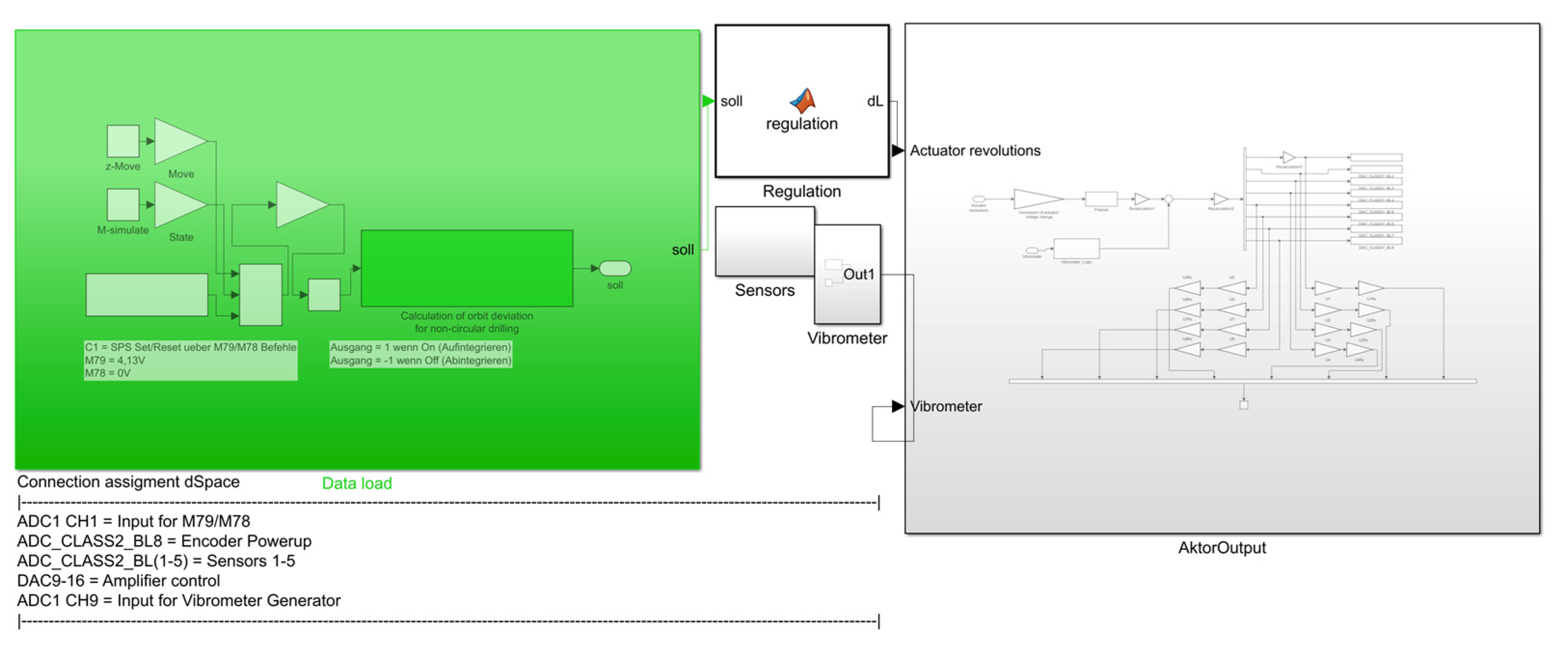
The Simulink model loaded into the dSpace (
Figure 6) consists of:
A data processing unit, which uses various parameters from the machine input. Using the neural engine, it calculates changes necessary for correct operation. With multiple repetitions, a training database and correction matrices are created based on previous errors in the form, measured with a tactile micrometer after processing.
A converting unit for the calculated data into the length of the actuators predicts the length change required for the piezoelectric actuator in the last calculated position to get required step of the drilling form at the next rotation angle .
A block of sensors and a block of additional devices (in this case, the laser vibrometer). The blocks are not always needed, only in the necessary experiments.
The output block transforms the required resizing of the actuators into voltage and controls all DACs. Also, it’s responsible for the safety and smooth operation of the amplifiers.
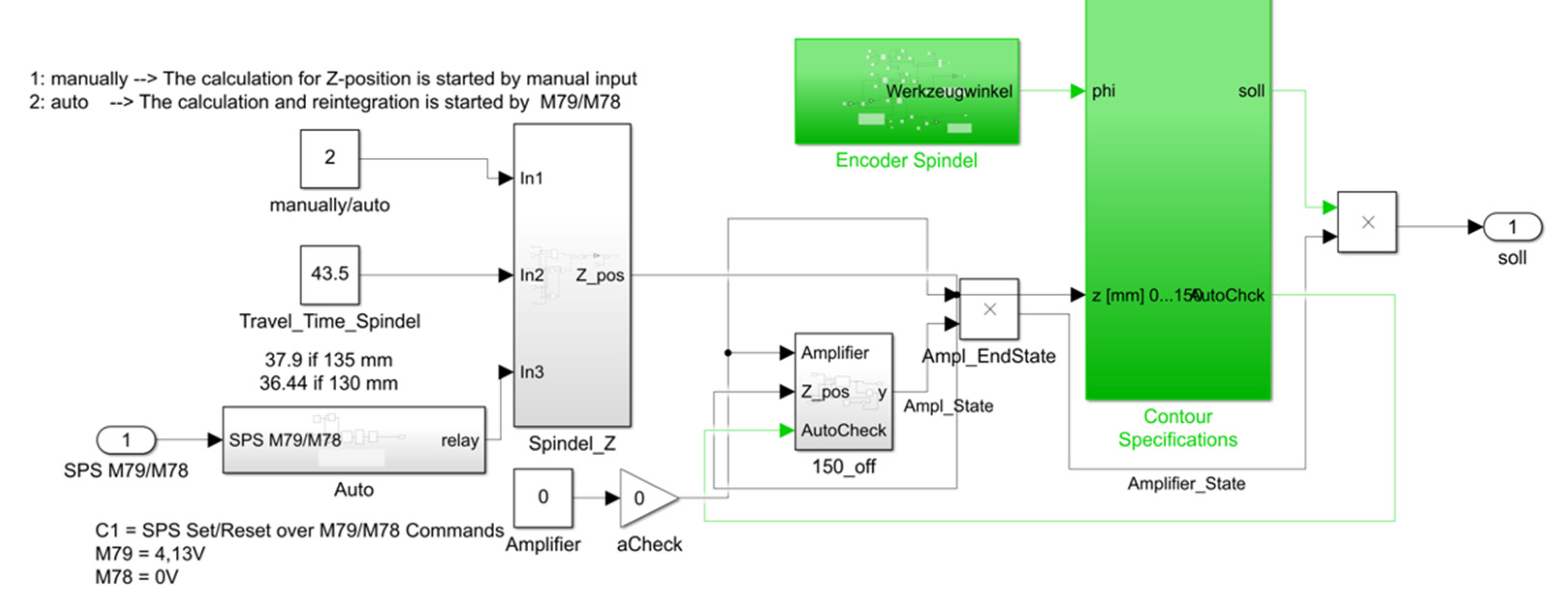
The data processing unit (
Figure 7) transfers the m-signal of the machine, the encoder data, the height of the given cylinder, the speed of the spindle downward, and the state of the amplifiers to the contour specification block with the neural engine. It analyses the exact rotation angle of the spindle and the depth of the drill at the moment. After that, a comparison with the previous errors analyses is carried out and the next step with the further rotation of the spindle is calculated.
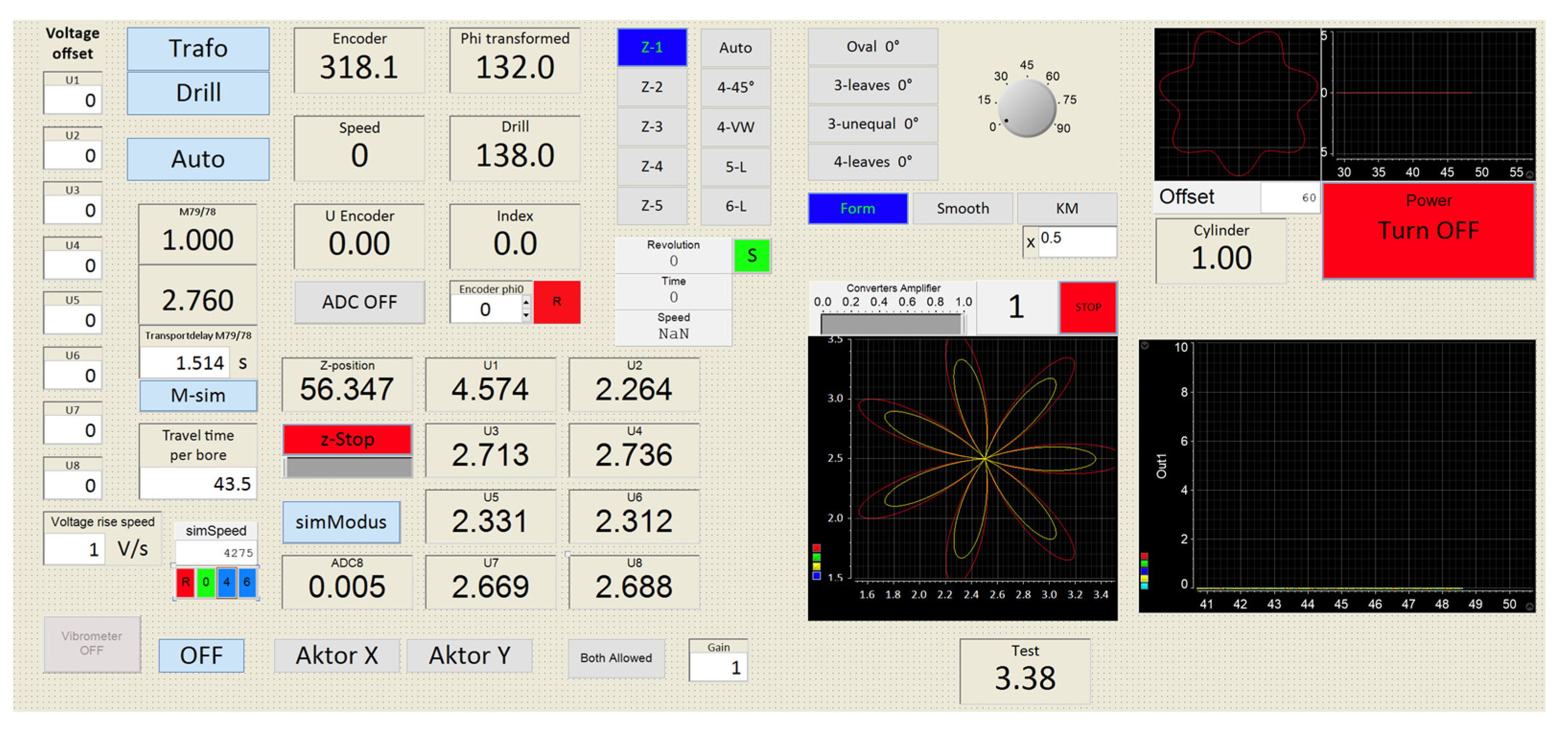
After model building and loading it into the dSpace module, the dSpace system can be controlled used previously built interface in dSpace ControlDesk software (
Figure 8). It was built to control initial voltage offset on the piezoelectric actuators, manual spindle Z-position set or turn on auto prediction of the position, get encoder signal or set virtual encoder in another coordinate system to facilitate modulation for the dynamics with different operating speeds, to train ML-Module while the spindle operates in air from the basic geometries or automatic process all 5 cylinders, control smoothness of the process, and control amount of the influence of the neural engine over the classic control (multiplying a coefficient of the influence to the matrix of the corrections–KM).
Experiments with new equipment are carried out as follows. A matrix of the spindle position in the cylinder is created with a step sufficient for the required drilling accuracy (for example, a matrix 721 × 75 for 0.5 degree of rotation step and 2 mm of step depth for the cylinder height of 150 mm). This matrix is interpolated for smooth operation of actuators and is calculated as the voltage for each of the 8 actuators, considering the errors of previous experiments, heating, the position of the actuator on the spindle, etc. Then the data is loaded into the control module (dSpace or microprocessor with DAC connected to actuators amplifiers). dSpace or microprocessor system also receive a signal from the spindle encoder and machine m-signal, which indicates the beginning and end of the downward movement of the drill. Knowing the speed of the drill Z-movement and the distance of the drill from the surface of the cylinder, the system calculates the depth position of the drill. Knowing the angle of the drill rotation and the depth of the drill, the control signal is applied, applying the required voltage to all 8 piezoelectric actuators controlling the drilling shape. After the drilling process, the cylinders are washed and sent to measure the shape with the tactile micrometer. Considering the errors, the training mode is then activated, and correction matrices are applied to correct the shape errors.
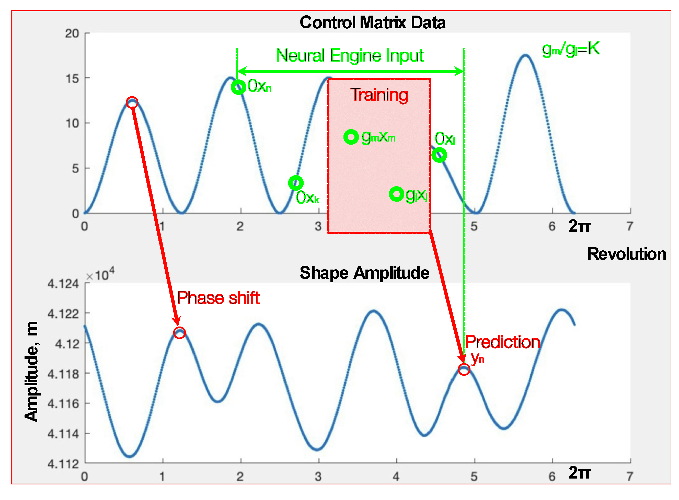
The method of diacoptic separation in combination with this hardware application with further optimisations in the learning module allows in areas with an insufficient reaction speed of the control system to predict the necessary control several steps after the arrival of measurements to the computational module (
Figure 9).
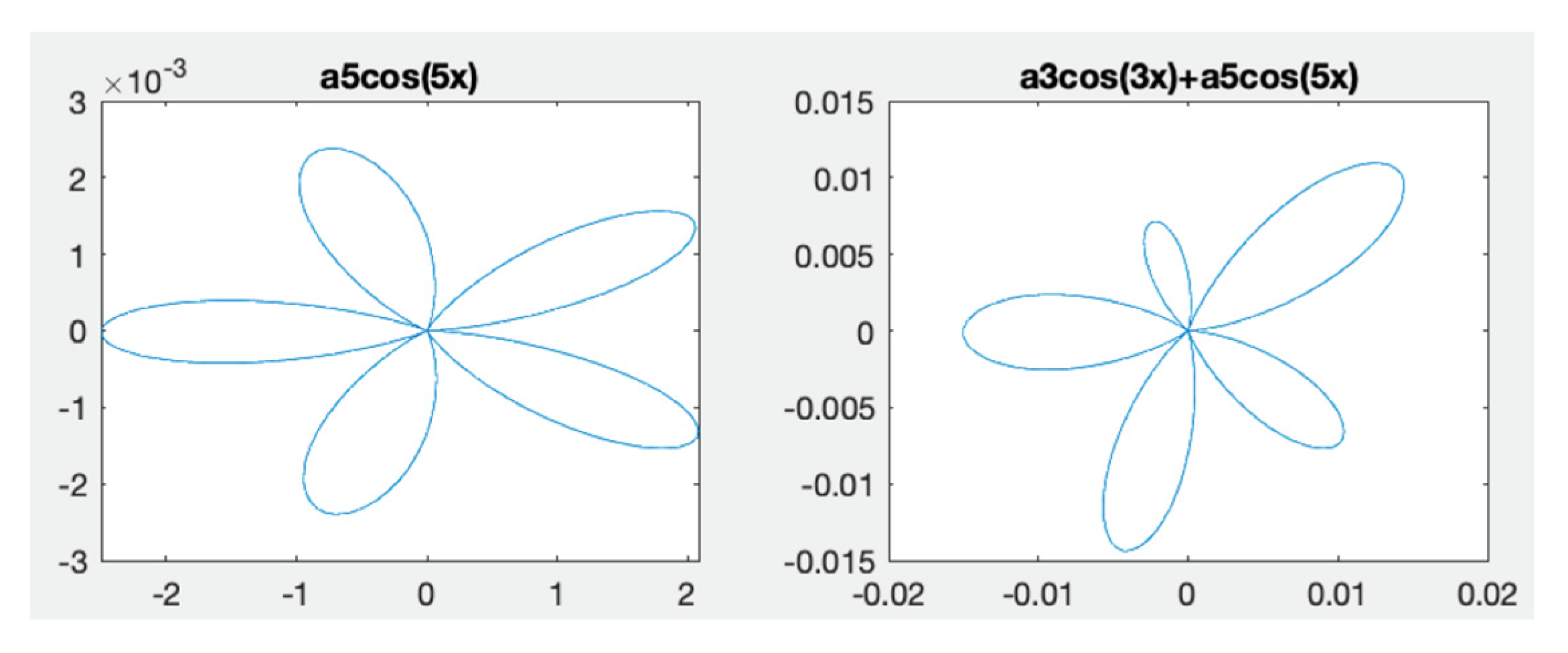
This process is similar to the analysis of the function’s harmonics. For simple drilling shapes (two-leaf, trefoil … six-leaf) it could be used as a harmonic analysis where strong deformation indicates the resonances of the machine, and small errors–noise. Coefficients a1, a2, … are the goal of the machine learning model training (
Figure 10).
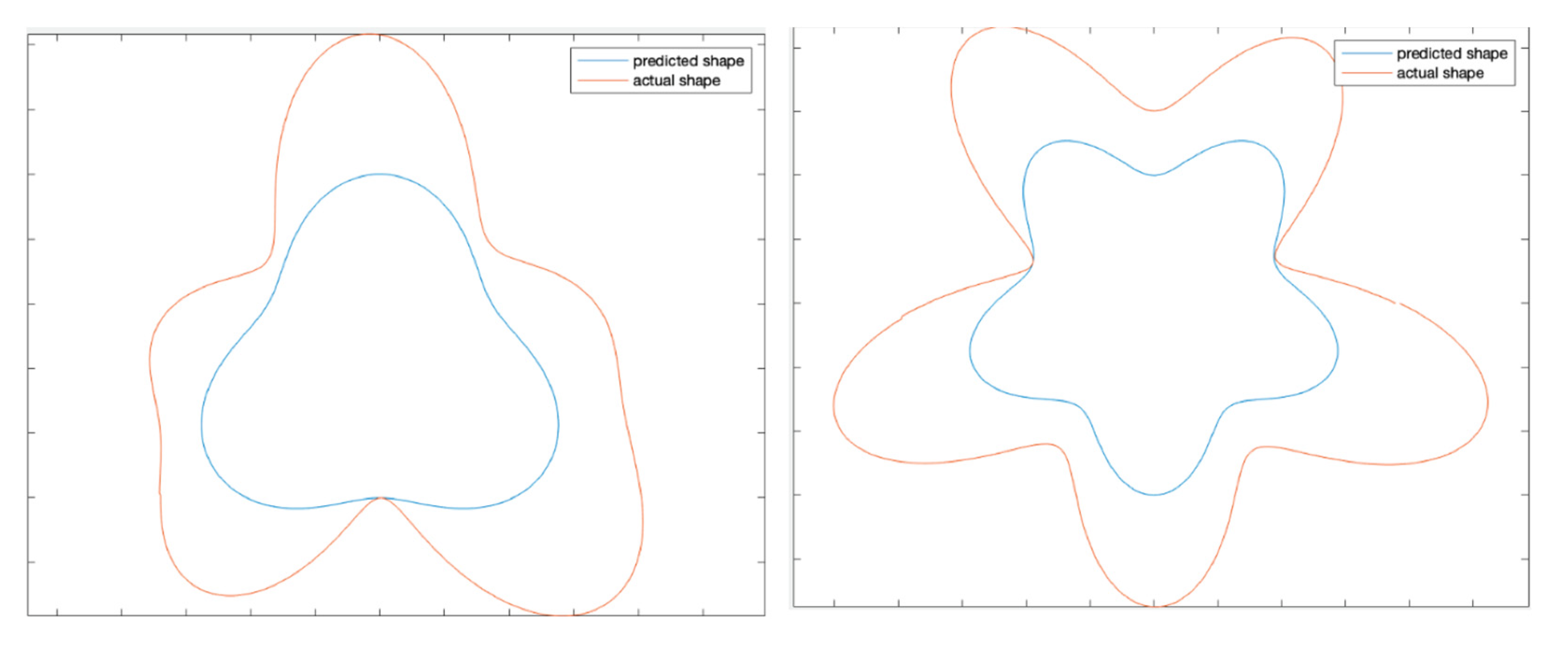
This shape was applied at a spindle speed of 4250 rpm at a drill depth in a cylinder of 100 mm. Here the strong influence of the 3rd harmonic, which distorts the shape, as well as the 5th harmonic, which leads to resonance with a 5-fold increase in the drilling amplitude, can be clearly seen. Instead of the shape, the resulting shape is with form with a little noise of the 2 and 7 harmonics. In this case, at a given depth at other speeds of spindle rotation (6000 rpm) or at a given speed of rotation but at a different depth, this resonance does not take place. So, the errors are local and even in such simple forms need diacoptics rather than pure machine learning techniques.
An analysis of the system state using a laser vibrometer also proves the locality of these resonances, which are either symmetric and simply increase amplitude of the figure shape, or asymmetric intrinsic mechanical resonances of the machine, which partially increase the cutting amplitude, thereby completely deforming the shape (
Figure 11).
The most noticeable errors that the control is not able to solve are when drilling the shapes of the 3 and 5 orders. The X and Y resonance at the 5 orders are similar and do not deform the shape while 3 order is deformed. After changing the drilling depth or spindle speed, the error rate is reduced by more than 100 times.
The shapes from this test look like those depicted in
Figure 12.
These problem areas can be simply isolated, with diacoptic separation of system states. By combining classical control with a neural engine, it is possible to analyse the necessary behaviour of the control system or calculate the necessary modulation form to correct the error or use the inertia and the mechanical resonance of the machine against the error.
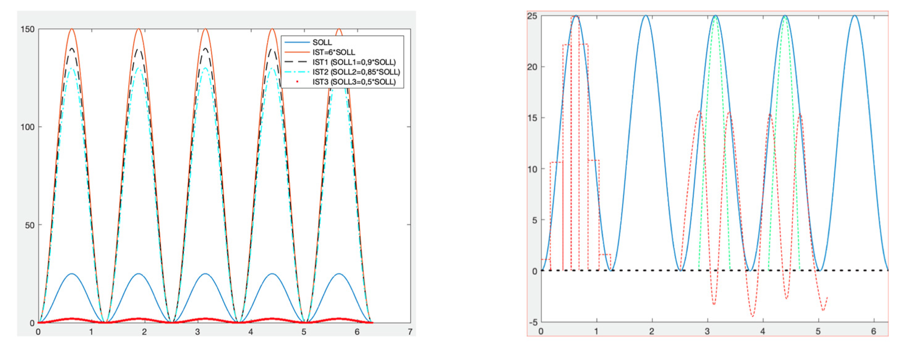
The problem during resonance is that by decreasing the control voltage, it is impossible to find the required amplitude.
Figure 13 shows the required cut shape in blue. When trying to decrease the control voltage, either the amplitude is still large, or the actuator stops responding and the cutting amplitude is too small. The next problem is that the spindle is controlled by eight piezoelectric actuators and not all actuators are in a state of resonance.
This problem is completely solved by using different modulation techniques on the state segments (
Figure 13).
When there is enough pulse width modulation in the figure of the 3rd order, the 5th order shape also requires a minus voltage signal for improved braking and cutter retraction for the next shaping leaves.
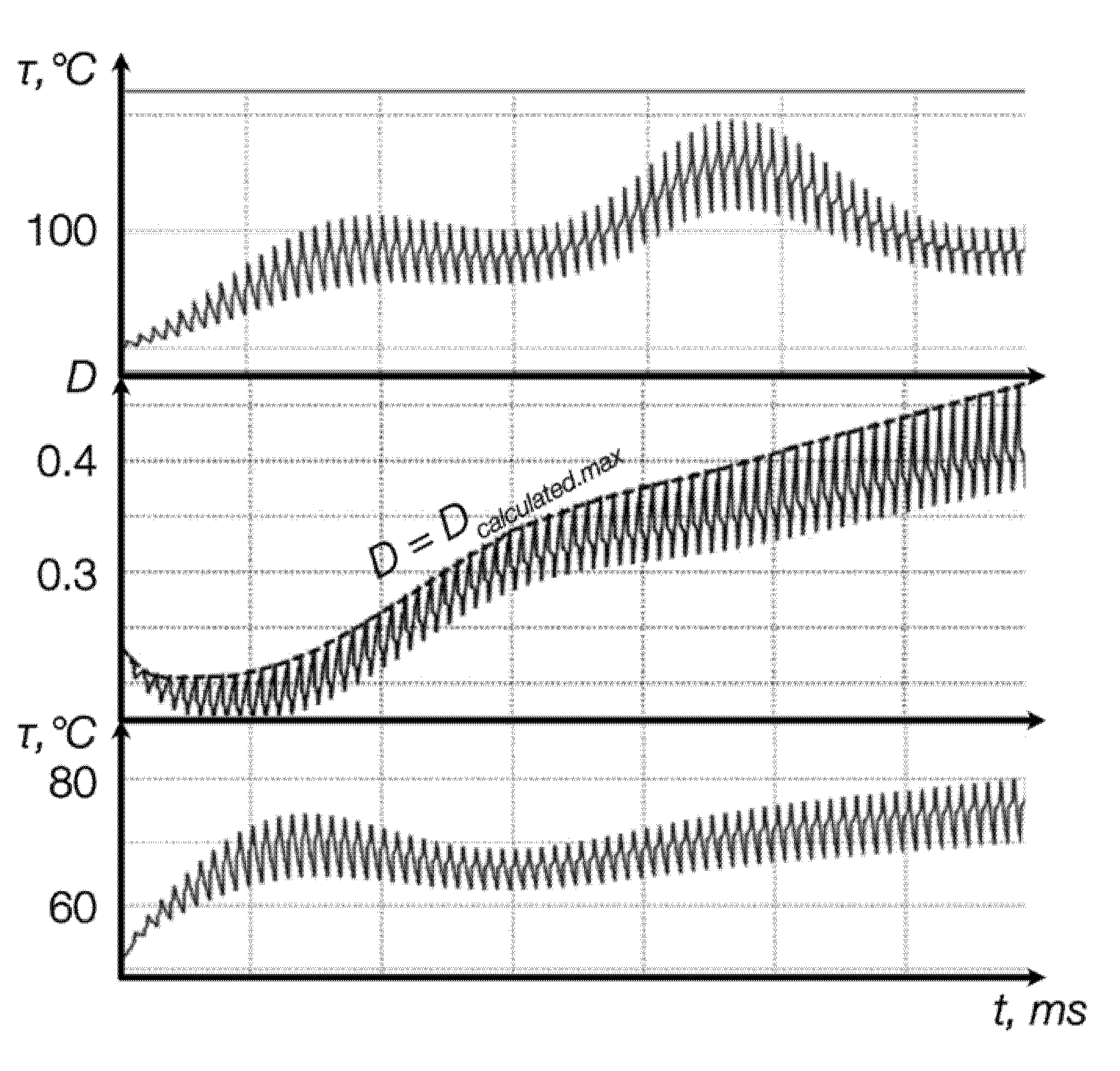
The state sections are not only limited by the dynamics of the device, but also by the electromagnetic and thermal components of the entire system. When modulating the signal, it also becomes possible to apply temperature feedback to control the pulse width ratio
of the control signal (
Figure 14). Methods, calculations, and construction of thermal feedback of the system are described in detail in previous publications [
1,
18].
This control has already made it possible to become independent of the bulky cooling systems of eight converters and piezoelectric actuators and to switch completely to passive control during processes from 5 to 15 min, depending on the load of the machine. In the previous version of the control, the solution against the resonance took place with the help of additional power sources, which was energy intensive. At the moment, instead of additional power supplies, capacitors connected in parallel to piezoelectric actuators are sufficient enough.
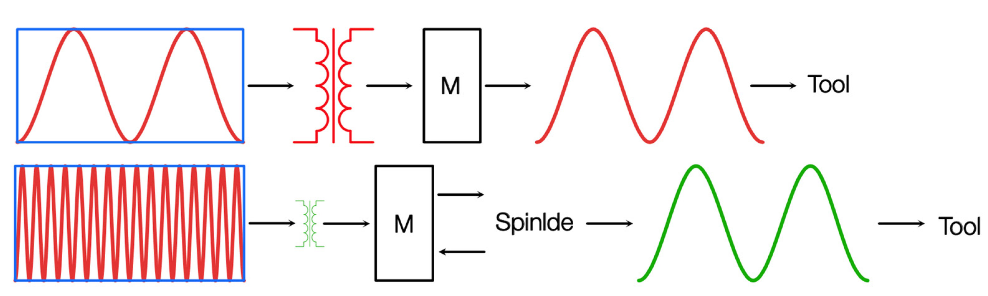
The next steps to improve the efficiency of devices and reduce CO
2 emissions are further optimisation of the system cooling, effective control with the transition to one converter instead of the eight, as well as reducing the size of the electromagnetic devices of the converters by switching to high-frequency control and using the inertia of the machine to damp these frequencies (
Figure 15).
Since the inertia of the spindle with a specific workpiece demonstrates inherent repeatability, the first tests were carried out to predict the behaviour of the spindle with high-frequency signals with the built-in neural engine of the system. These tests with adjustments were successful and are the subject of future studies.
5. Conclusions
In this study, an intelligent control system was created for the operating modes of the non-circular drilling machine, in which the control goes beyond the limits of the regulator and an iterative process, including repeatable cleaning and measuring of the tool, is necessary. In addition to simplifying the iterative process, the potential of this research was used for energy and thermal optimisation of management, which makes it possible to bring this project to a new level: effective reduction of CO2 emissions into the environment.
The end device is operated by the cascades of controlled voltage inverters and a neural engine on a chip. This system is built to apply the methods and models described in previous publications for calculating the state of the system on the constancy intervals, selected using the diacoptics methods with further calculation of the stability of the method and the stability of the control itself.
The transition of the operation of eight converters and piezoelectric actuators to passive cooling has already been tested, as well as the replacement of additional power supplies designed to stabilise the system with passive components. In addition to efficient process control in areas where the control previously did not have time to respond, improvements have been made in the energy and thermal characteristics of the system. The previous system lacked even active cooling; piezoelectric actuators overheated, changing their properties, and amplifiers had to be turned off periodically due to insulation melting.
Furthermore, the current effectiveness of the neural engine is being tested for predicting the behaviour of highly inertial mechanics in response to a high-frequency signal. With positive results in this direction, a multi-pronged improvement in the energy efficiency of the device will be possible: the transition of the system control parts building to reused materials; a significant reduction in the size of the system; and reducing the need for high-energy converters.


