
Critical Conditions for the Ignition of a Gel Fuel under Different Heating Schemes


Abstract
:
1. Introduction
2. Physical and Mathematical Models
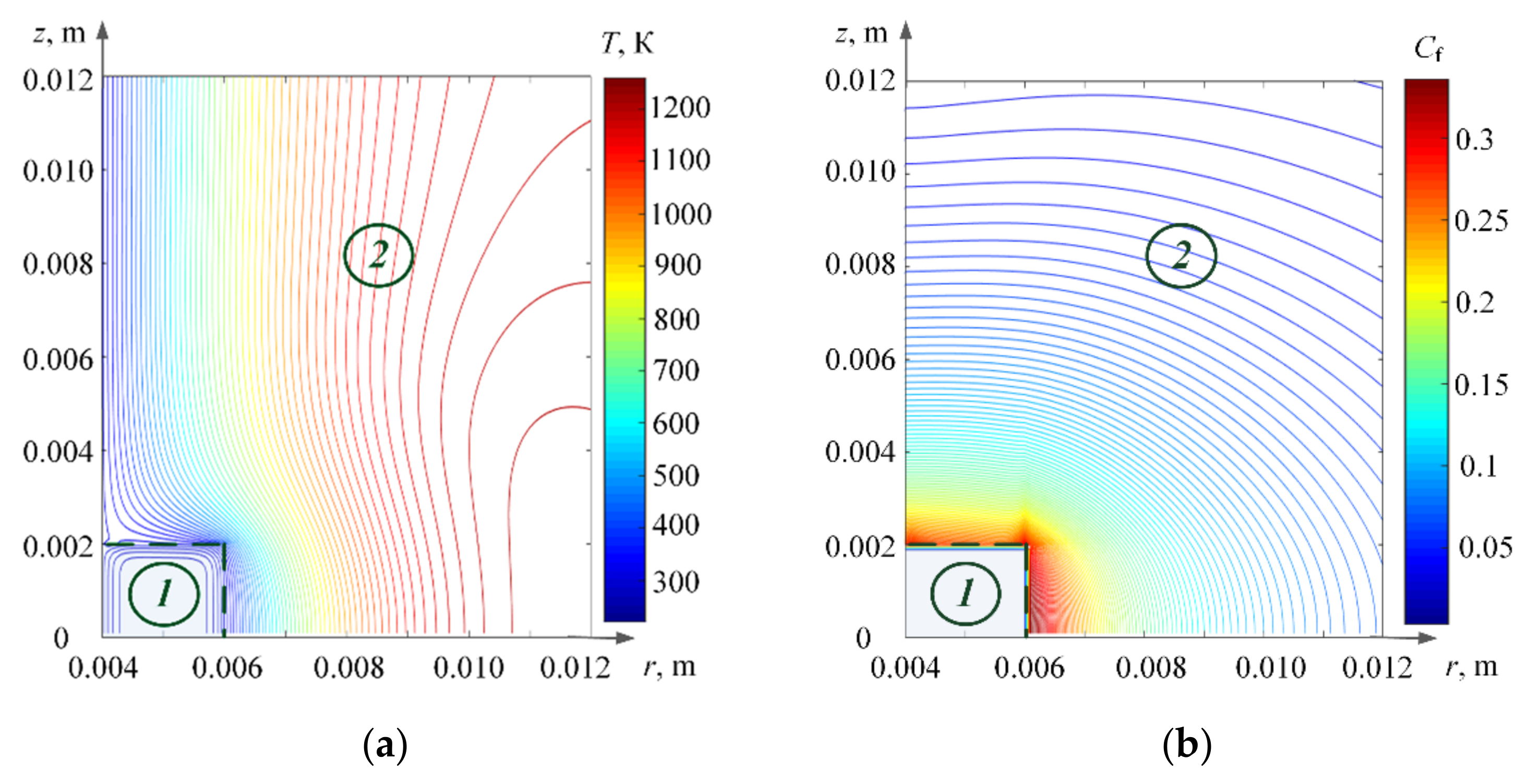
2.1. Dominance of Conductive Heat Flux on the Surface of a Gel Fuel Sample
2.2. Dominance of Radiant Heat Flux on the Surface of the Gel Fuel
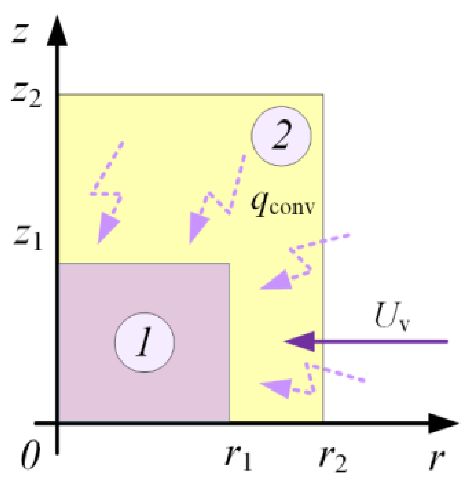
2.3. Dominance of Convective Heat Flux on the Surface of the Gel Fuel
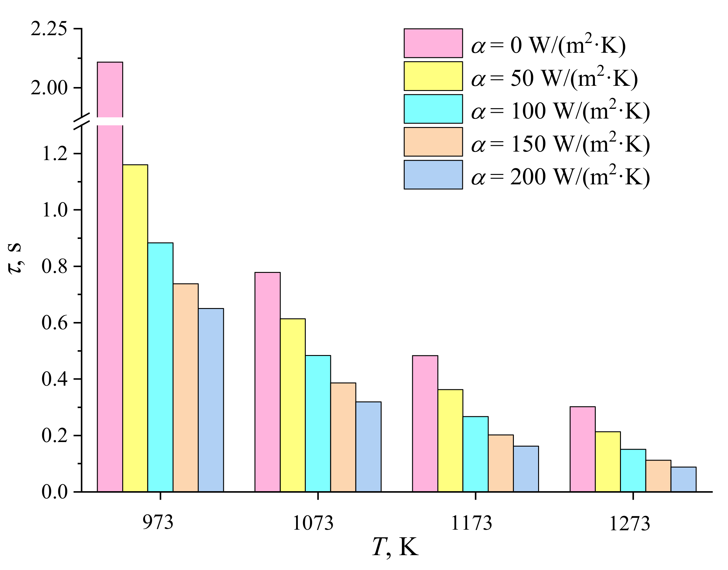
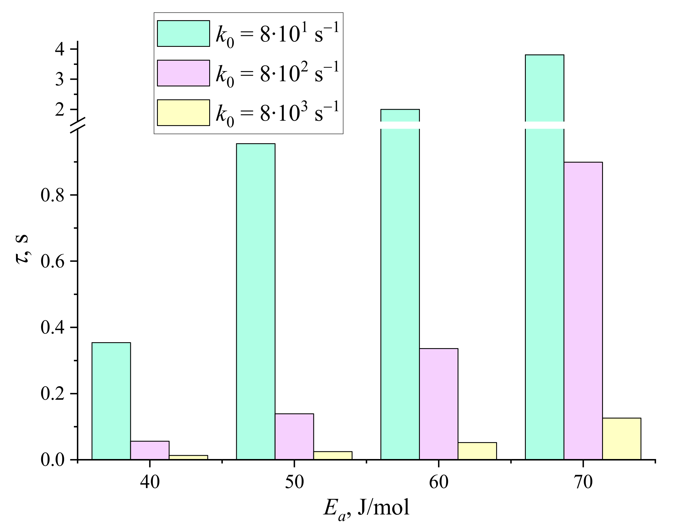
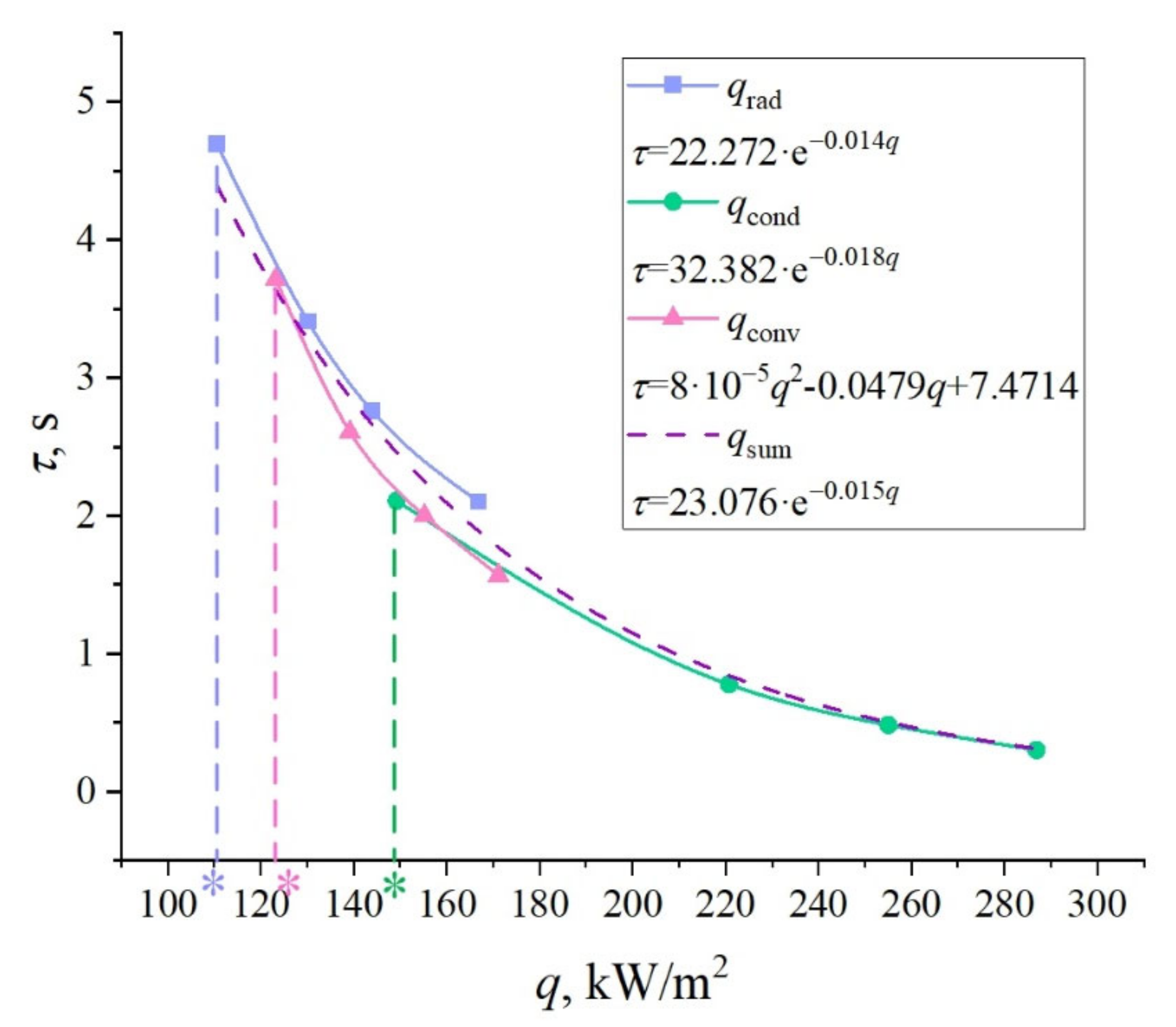
3. Results and Discussion
4. Conclusions
Author Contributions
Funding
Institutional Review Board Statement
Informed Consent Statement
Data Availability Statement
Conflicts of Interest
Nomenclature
| Greek letters | |
| α | Convection heat transfer coefficient, W/(m2·K) |
| Ψ | Stream function, m2/s |
| ω | Vorticity vector, s−1 |
| β | Coefficient of thermal expansion, K−1 |
| ε | Emissivity coefficient |
| φ | Dimensionless combustible part of fuel |
| λ | Thermal conductivity, W/(m·K) |
| ν | Kinetic viscosity, m2/s |
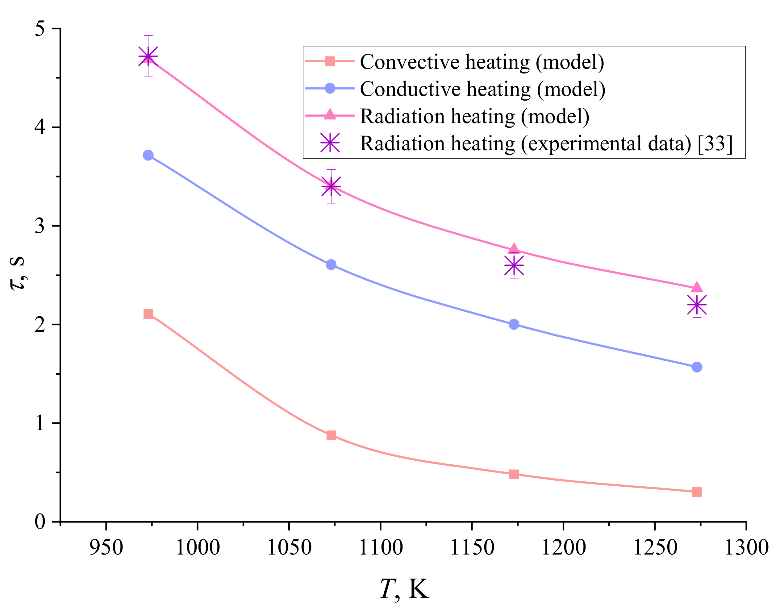
| τ | Ignition delay time, s |
| ρ | Density, kg/m3 |
| σ | Stefan–Boltzmann constant, W/(m2·K4) |
| Latin letters | |
| A | Accommodation coefficient |
| a | Temperature conductivity coefficient, m2/s |
| C | Specific heat, J/(kg·K) |
| Co | Dimensionless concentration of oxidant vapors |
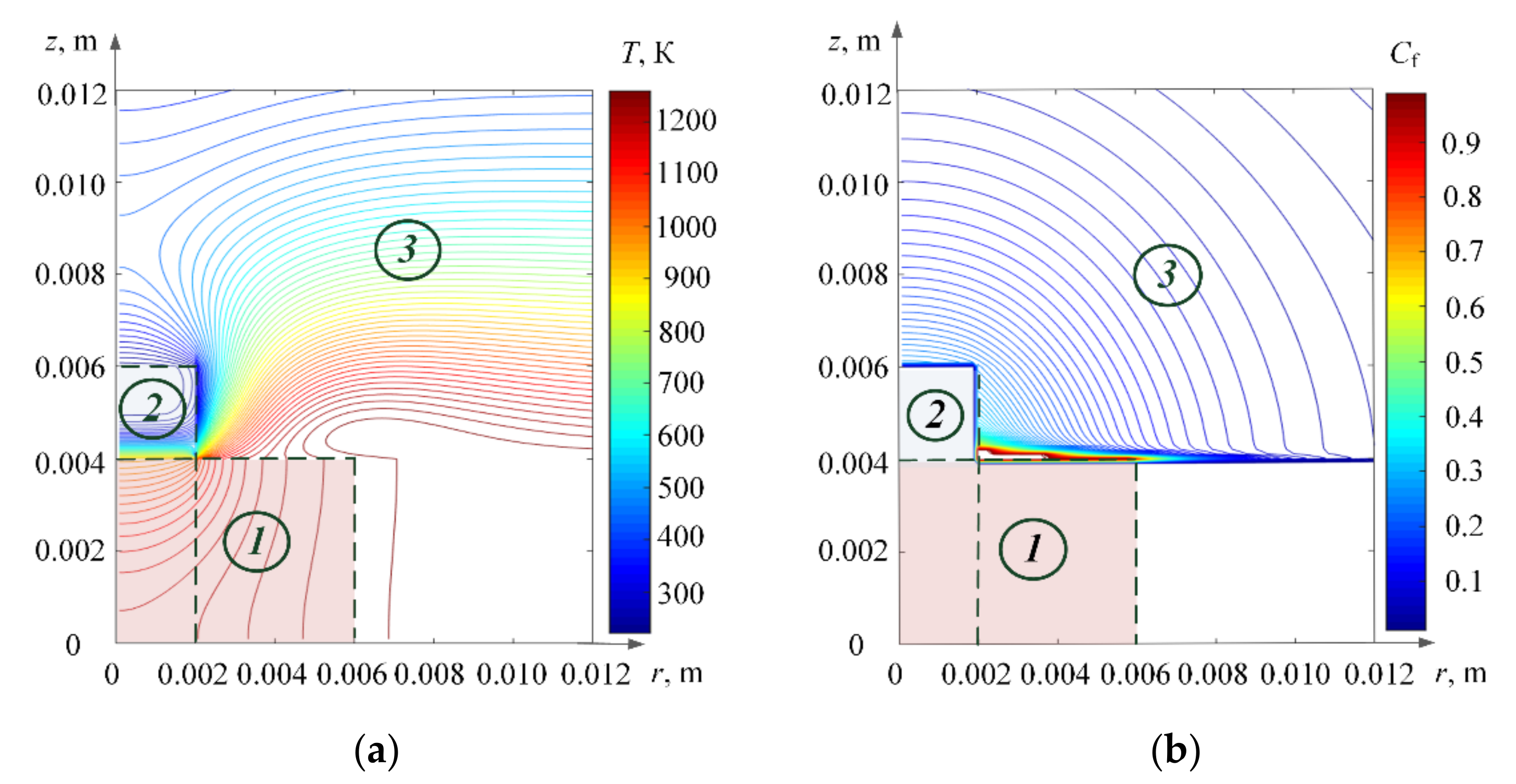
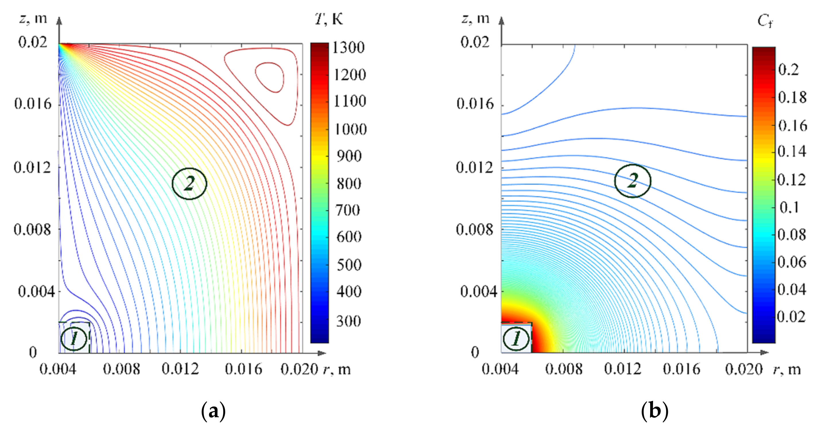
| Cf | Dimensionless concentration of fuel vapors |
| Cg | Dimensionless inert gas concentration |
| D | Diffusion coefficient, m2/s |
| d | Diameter of fuel particle, m |
| Ea | Activation energy of oxidizing reaction, J/mole |
| g | Gravity acceleration, m/s2 |
| k0 | Oxidizing reaction pre-exponential factor, s−1 |
| M | Evaporating component molecular mass, kg/kmole |
| Nu | Nusselt number |
| Pe | Vapor pressure over the fuel surface, N/m2 |
| Pen | Equilibrium vapor pressure, Pa |
| Pr | Prandtl number |
| Re | Reynolds number |
| Qef | Thermal effect of fuel vaporization, J/kg |
| Qeo | Thermal effect of oxidant evaporation, J/kg |
| Qmelt | Thermal effect of melting of the “fuel–oxidizer” system, J/kg |
| qconv | Heat flux density removed from the heating source due to conductive heat transfer, W/m2 |
| qconv | Heat flux density removed from the heating source due to convective heat transfer, W/m2 |
| qrad | Heat flux density removed from the heating source due to radiative heat transfer, W/m2 |
| r, z | Cylindrical system coordinates, m |
| rL, zL | Dimensions of solution domain, m |
| Rp, Zp | Cylinder dimensions, m |
| R | The universal gas constant, J/(mole·K) |
| T | Temperature, K |
| Uv | Diffusion rate, m/s |
| Vmelt | Linear melting rate, m/s |
| Wef | Fuel evaporation mass rate, kg/(m2·s) |
| Weo | Oxidant evaporation mass rate, kg/(m2·s) |
| Wmelt | Mass melting rate of the “fuel–oxidizer” system, kg/(m2·s) |
| Indices | |
| 0 | Initial moment of time |
| 12 | Fuel vapors |
| 13 | Oxidizer vapors |
| a | Air |
| ef | Fuel vaporization |
| eo | Oxidant evaporation |
| f | Fuel |
| h | Surface |
| L | Solution area |
| melt | Melting |
| o | Oxidizing agent |
References
- Vujanović, M.; Wang, Q.; Mohsen, M.; Duić, N.; Yan, J. Recent progress in sustainable energy-efficient technologies and environmental impacts on energy systems. Appl. Energy 2021, 283, 116280. [Google Scholar] [CrossRef]
- Xiao, Y.; Xia, Z.; Huang, L.; Ma, L.; Yang, D. Experimental investigation of the effects of chamber length and boron content on boron-based gel fuel ramjet performance. Acta Astronaut. 2019, 160, 101–105. [Google Scholar] [CrossRef]
- Ciezki, H.K.; Naumann, K.W. Some Aspects on Safety and Environmental Impact of the German Green Gel Propulsion Technology. Propellants Explos. Pyrotech. 2016, 41, 539–547. [Google Scholar] [CrossRef]
- Natan, B.; Rahimi, S. The status of gel propellants in year 2000. Int. J. Energy Mater. Chem. Propuls. 2002, 5, 172–194. [Google Scholar] [CrossRef]
- Cao, Q.L.; Wu, W.T.; Liao, W.H.; Feng, F.; Massoudi, M. Effects of temperature on the flow and heat transfer in gel fuels: A numerical study. Energies 2020, 13, 821. [Google Scholar] [CrossRef] [Green Version]
- Rahimi, S.; Peretz, A.; Natan, B. Rheological Matching of Gel Propellants. J. Propuls. Power 2012, 26, 376–378. [Google Scholar] [CrossRef]
- Vershinina, K.Y.; Glushkov, D.O.; Nigay, A.G.; Yanovsky, V.A.; Yashutina, O.S. Oil-Filled Cryogels: New Approach for Storage and Utilization of Liquid Combustible Wastes. Ind. Eng. Chem. Res. 2019, 58, 6830–6840. [Google Scholar] [CrossRef]
- Verma, M.; Gupta, B.L.; Pandey, M. Formulation & Storage Studies on Hydrazine-Based Gelled Propellants. Def. Sci. J. 1996, 46, 435–442. [Google Scholar] [CrossRef] [Green Version]
- Sun, D.; Cai, W.; Li, C.; Lu, J. Experimental study on atomization characteristics of high-energy-density fuels using a fuel slinger. Energy 2021, 234, 121222. [Google Scholar] [CrossRef]
- Won, J.; Baek, S.W.; Kim, H.; Lee, H. The Viscosity and Combustion Characteristics of Single-Droplet Water-Diesel Emulsion. Energies 2019, 12, 1963. [Google Scholar] [CrossRef] [Green Version]
- Glushkov, D.; Paushkina, K.; Shabardin, D.; Strizhak, P. Environmental aspects of converting municipal solid waste into energy as part of composite fuels. J. Clean. Prod. 2018, 201, 1029–1042. [Google Scholar] [CrossRef]
- Caton, J.A. The thermodynamic characteristics of high efficiency, internal-combustion engines. Energy Convers. Manag. 2012, 58, 84–93. [Google Scholar] [CrossRef]
- Liu, Z.; Hu, X.; He, Z.; Wu, J. Experimental Study on the Combustion and Microexplosion of Freely Falling Gelled Unsymmetrical Dimethylhydrazine (UDMH) Fuel Droplets. Energies 2012, 5, 3126–3136. [Google Scholar] [CrossRef]
- Nachmoni, G.; Natan, B. Combustion characteristics of gel fuels. Combust. Sci. Technol. 2000, 156, 139–157. [Google Scholar] [CrossRef]
- Mishra, D.P.; Patyal, A.; Padhwal, M. Effects of gellant concentration on the burning and flame structure of organic gel propellant droplets. Fuel 2011, 90, 1805–1810. [Google Scholar] [CrossRef]
- Padwal, M.B.; Mishra, D.P. Experimental Characterization of Gelled Jet A1 Spray Flames. Flow Turbul. Combust. 2016, 97, 295–337. [Google Scholar] [CrossRef]
- Jyoti, B.V.S.; Naseem, M.S.; Baek, S.W. Hypergolicity and ignition delay study of pure and energized ethanol gel fuel with hydrogen peroxide. Combust. Flame 2017, 176, 318–325. [Google Scholar] [CrossRef]
- Glushkov, D.O.; Nigay, A.G.; Yashutina, O.S. The gel fuel ignition at local conductive heating. Int. J. Heat Mass Transf. 2018, 127, 1203–1214. [Google Scholar] [CrossRef]
- Solomon, Y.; Natan, B.; Cohen, Y. Combustion of gel fuels based on organic gellants. Combust. Flame 2009, 156, 261–268. [Google Scholar] [CrossRef]
- He, B.; Nie, W.; He, H. Unsteady Combustion Model of Nonmetalized Organic Gel Fuel Droplet. Energy Fuels 2012, 26, 6627–6639. [Google Scholar] [CrossRef]
- Kunin, A.; Greenberg, J.B.; Natan, B. A simple phenomenological model of an organic gel spray diffusion flame. Combust. Sci. Technol. 2008, 180, 27–44. [Google Scholar] [CrossRef]
- Kunin, A.; Natan, B.; Greenberg, J.B. Theoretical Model of the Transient Combustion of Organic-Gellant-Based Gel Fuel Droplets. J. Propuls. Power 2012, 26, 765–771. [Google Scholar] [CrossRef]
- Glushkov, D.O.; Kuznetsov, G.V.; Strizhak, P.A.; Taburchinov, R.I. Numerical simulation of gel fuel gas-phase ignition by a local source of limited heat content. Acta Astronaut. 2019, 163, 44–53. [Google Scholar] [CrossRef]
- Glushkov, D.O.; Kosintsev, A.G.; Kuznetsov, G.V.; Vysokomorny, V.S. Numerical simulation of ignition of a typical gel fuel particle, based on organic polymer thickener, in a high-temperature air medium. Acta Astronaut. 2021, 178, 272–284. [Google Scholar] [CrossRef]
- Liu, N.; Ma, B.; Liu, F.; Huang, W.; Xu, B.; Qu, L.; Yang, Y. Progress in research on composite cryogenic propellant tank for large aerospace vehicles. Compos. Part A Appl. Sci. Manuf. 2021, 143, 106297. [Google Scholar] [CrossRef]
- Yilmaz, N. Performance and emission characteristics of a diesel engine fuelled with biodiesel–ethanol and biodiesel–methanol blends at elevated air temperatures. Fuel 2012, 94, 440–443. [Google Scholar] [CrossRef]
- Li, N.; Mao, G.; Liu, Y. Effect of the Evaluation and Mechanism Analysis of a Novel Nanohybrid Pour Point Depressant on Facilitating Flow Properties of Crude Oil. Energy Fuels 2018, 32, 10563–10570. [Google Scholar] [CrossRef]
- Kuznetsov, G.V.; Strizhak, P.A. Computational Investigation of Heat and Mass Transfer Processes in a Gel-Like Fuel Ignited by a Limited-Capacity Source. J. Eng. Phys. Thermophys. 2013, 86, 695–704. [Google Scholar] [CrossRef]
- Gaydukova, O.S.; Misyura, S.Y.; Strizhak, P.A. Investigating regularities of gas hydrate ignition on a heated surface: Experiments and modelling. Combust. Flame 2021, 228, 78–88. [Google Scholar] [CrossRef]
- Glushkov, D.O.; Kuznetsov, G.V.; Nigay, A.G.; Yashutina, O.S. Heat and mass transfer induced by the ignition of single gel propellant droplets. J. Energy Inst. 2019, 92, 1944–1955. [Google Scholar] [CrossRef]
- Yang, Z.; Adeosun, A.; Kumfer, B.M.; Axelbaum, R.L. An approach to estimating flame radiation in combustion chambers containing suspended-particles. Fuel 2017, 199, 420–429. [Google Scholar] [CrossRef] [Green Version]
- Paskonov, V.M.; Polezhaev, V.I.; Chudov, L.A. Numerical Modeling of Heat and Mass Transfer Processes; Nauka: Moscow, Russia, 1984. [Google Scholar]
- Glushkov, D.O.; Nigay, A.G.; Yanovsky, V.A.; Yashutina, O.S. Effects of the Initial Gel Fuel Temperature on the Ignition Mechanism and Characteristics of Oil-Filled Cryogel Droplets in the High-Temperature Oxidizer Medium. Energy Fuels 2019, 33, 11812–11820. [Google Scholar] [CrossRef]
- Kutateladze, S.S.; Leont’ev, A.I. Heat Transfer, Mass Transfer, and Friction in Turbulent Boundary Layers; Hemisphere: New York, NY, USA, 1989. [Google Scholar]
- Glushkov, D.O.; Pleshko, A.O.; Yashutina, O.S. Influence of heating intensity and size of gel fuel droplets on ignition characteristics. Int. J. Heat Mass Transf. 2020, 156, 119895. [Google Scholar] [CrossRef]
- Glushkov, D.O.; Kuznetsov, G.V.; Strizhak, P.A. Stability of composite solid propellant ignition by a local source of limited energy capacity. Combust. Explos. Shock Waves 2014, 50, 670–675. [Google Scholar] [CrossRef]


| Constant | Symbol | Value | Unit of Measurement |
|---|---|---|---|
| Diffusion coefficient | D | 7.83 × 10⁻⁵ | m2/s |
| Oxidizing reaction activation energy | Ea | 60 × 103 | J/mol |
| Oxidizing reaction pre-exponential factor | k0 | 8 × 101 | s−1 |
| Specific heat of gel fuel | Cf | 1380 | J/(kg·K) |
| Temperature of gel fuel | Tf | 203 | K |
| Temperature of surface under radiation heating | Th | 873–1273 | K |
| Temperature of air | Ta | 873–1273 | K |
| Thermal effect of oxidant evaporation | Qeo | 38 × 106 | J/kg |
| Thermal effect of fuel vaporization | Qef | 0.14 × 10⁶ | J/kg |
| Thermal effect of vaporization of the thickener | Qispz | 0.26 × 10⁶ | J/kg |
| Fuel evaporation mass rate | Wef | 25 × 10−3 | kg/(m2∙s) |
| Oxidant evaporation mass rate | Weo | 15.3 × 10⁻³ | kg/(m2∙s) |
| Diffusion rate | Uv | 0–6 | m/s |
| Convection heat transfer coefficient | α | 0–200 | W/(m2∙K) |
| Coefficient of thermal expansion | β | 0.001 | K−1 |
| Gravity acceleration | g | 9.8 | m/s2 |
| Emissivity | ε | 0.85–0.99 | - |
| Kinetic viscosity | υ | 14.1 × 10⁻⁶ | m2/s |
| Density of gel fuel | ρf | 1010 | kg/m3 |
| Thermal conductivity of gel fuel | λf | 0.16 | W/(m·K) |
| Dimensionless combustible part of fuel | φ | 0.5 | - |
| T, K | τ, s at ε = 0.85 | τ, s at ε = 0.90 | τ, s at ε = 0.95 | τ, s at ε = 0.99 |
|---|---|---|---|---|
| 873 | 8.776 | 8.776 | 8.766 | 8.763 |
| 973 | 4.691 | 4.690 | 4.688 | 4.688 |
| 1073 | 3.407 | 3.406 | 3.405 | 3.405 |
| 1173 | 2.757 | 2.756 | 2.756 | 2.756 |
| 1273 | 2.366 | 2.366 | 2.366 | 2.366 |
Publisher’s Note: MDPI stays neutral with regard to jurisdictional claims in published maps and institutional affiliations. |
© 2021 by the authors. Licensee MDPI, Basel, Switzerland. This article is an open access article distributed under the terms and conditions of the Creative Commons Attribution (CC BY) license (https://creativecommons.org/licenses/by/4.0/).
Share and Cite
Gaidukova, O.; Strizhak, P. Critical Conditions for the Ignition of a Gel Fuel under Different Heating Schemes. Energies 2021, 14, 7083. https://doi.org/10.3390/en14217083
Gaidukova O, Strizhak P. Critical Conditions for the Ignition of a Gel Fuel under Different Heating Schemes. Energies. 2021; 14(21):7083. https://doi.org/10.3390/en14217083
Chicago/Turabian StyleGaidukova, Olga, and Pavel Strizhak. 2021. "Critical Conditions for the Ignition of a Gel Fuel under Different Heating Schemes" Energies 14, no. 21: 7083. https://doi.org/10.3390/en14217083