
Free-Piston Stirling Engine Technologies and Models: A Review


Abstract
:
1. Introduction
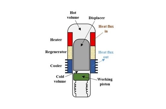
2. Free-Piston Stirling Engine Configuration
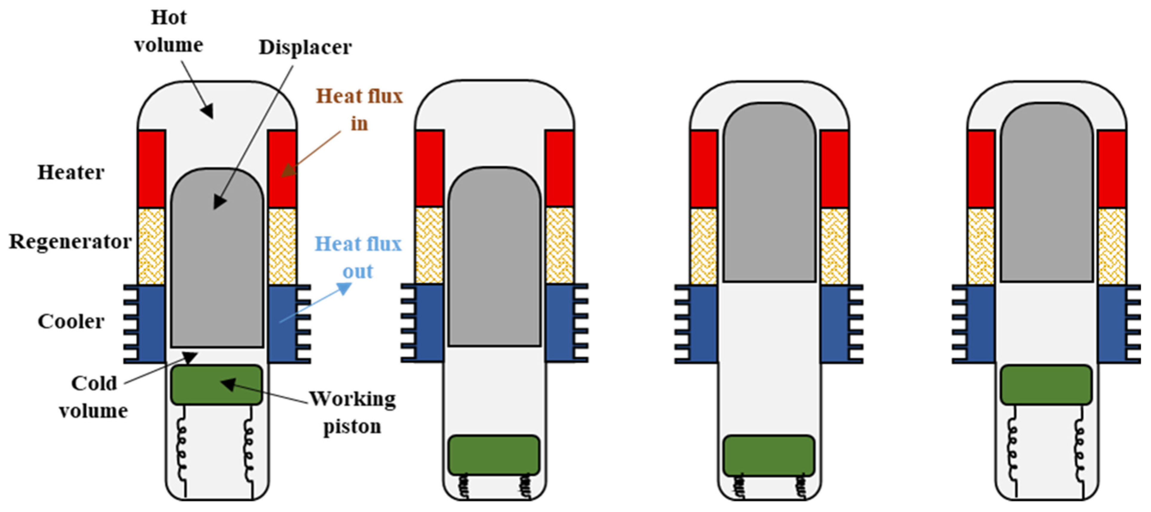
2.1. Operation Mode
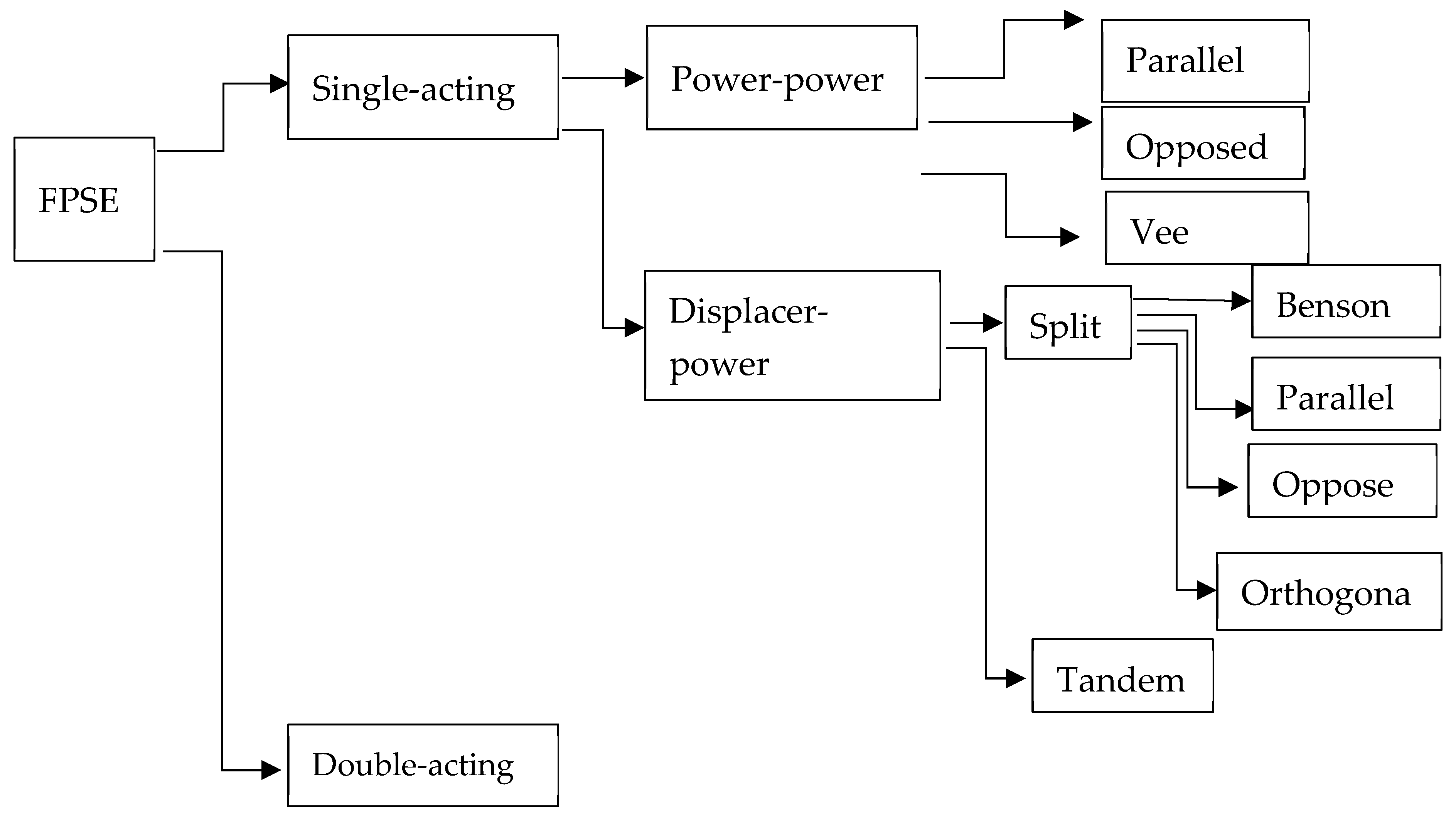
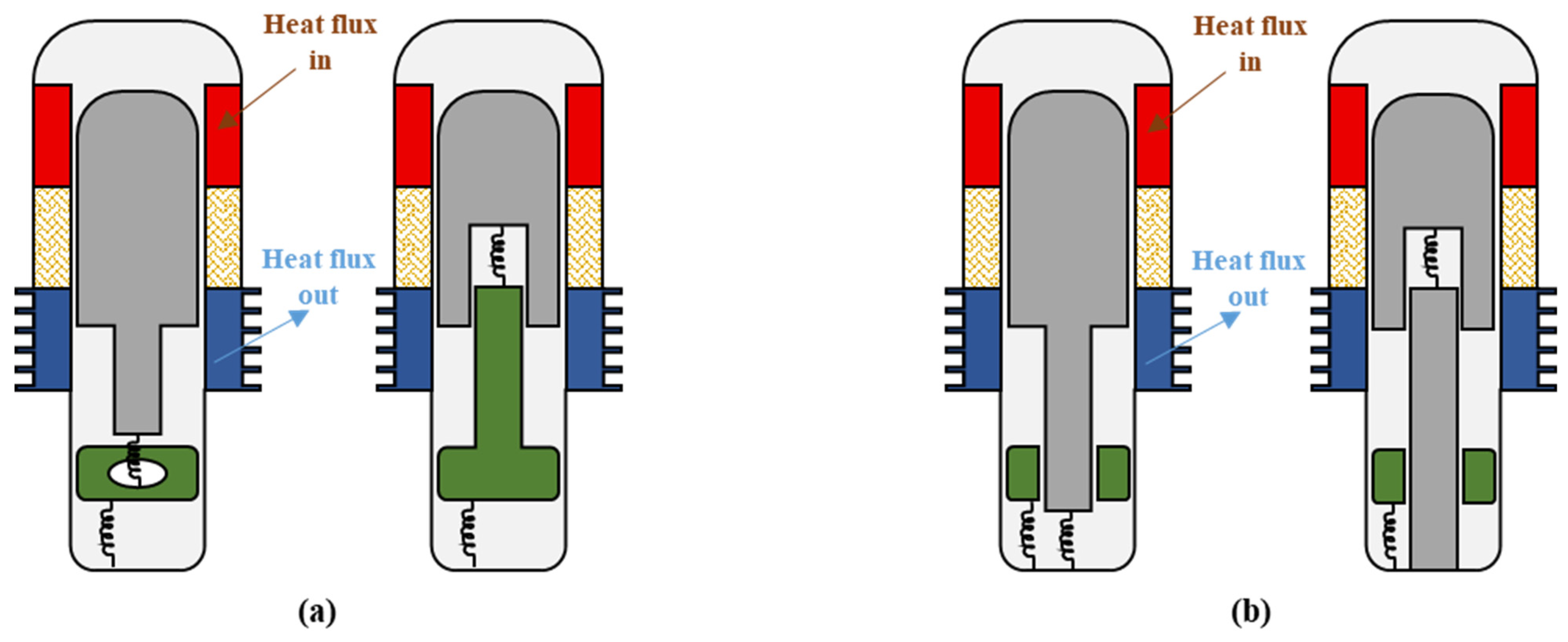
2.2. Classification
3. Free-Piston Stirling Engine Applications
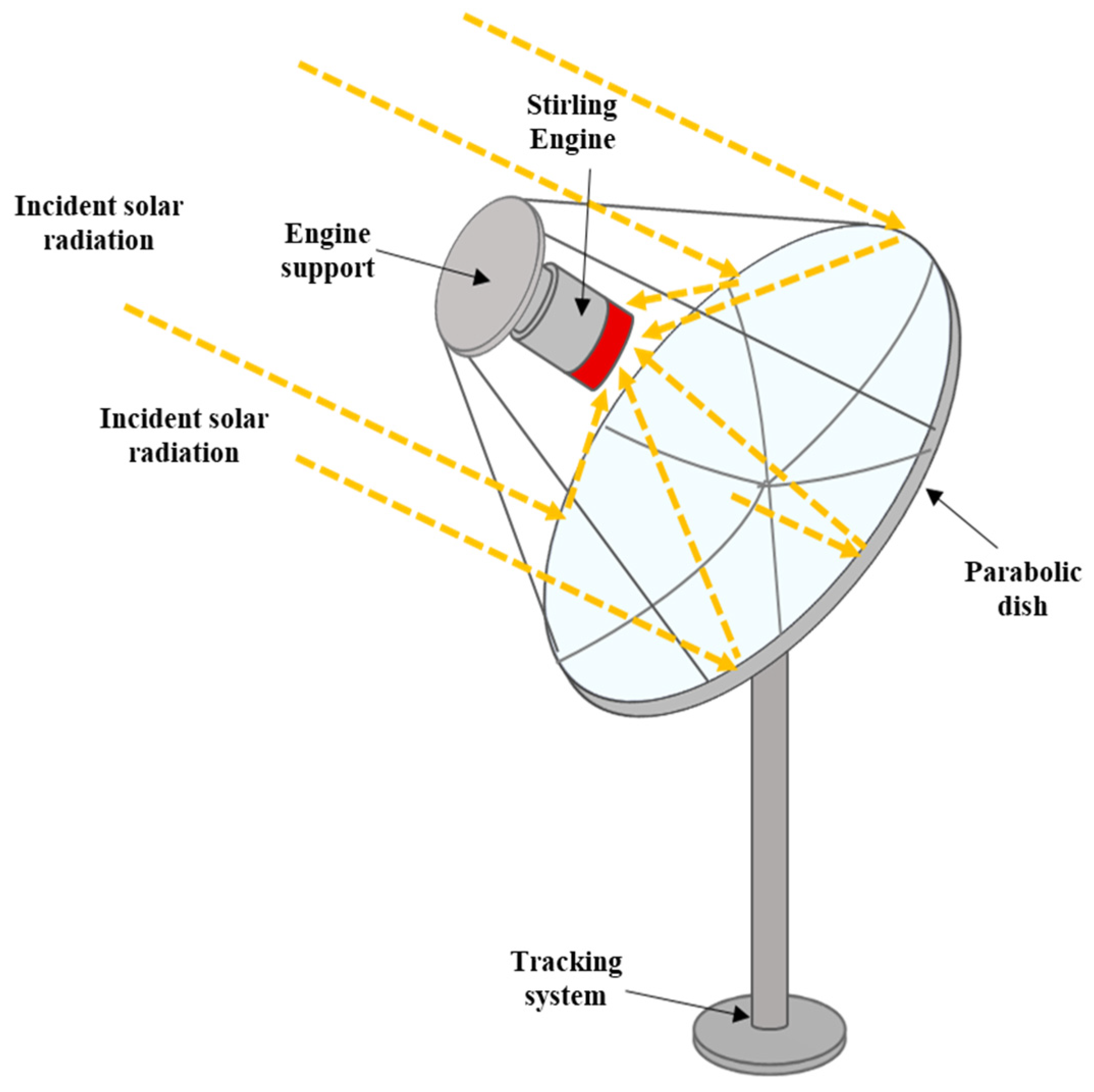
3.1. Dish Stirling
3.2. Cryocoolers
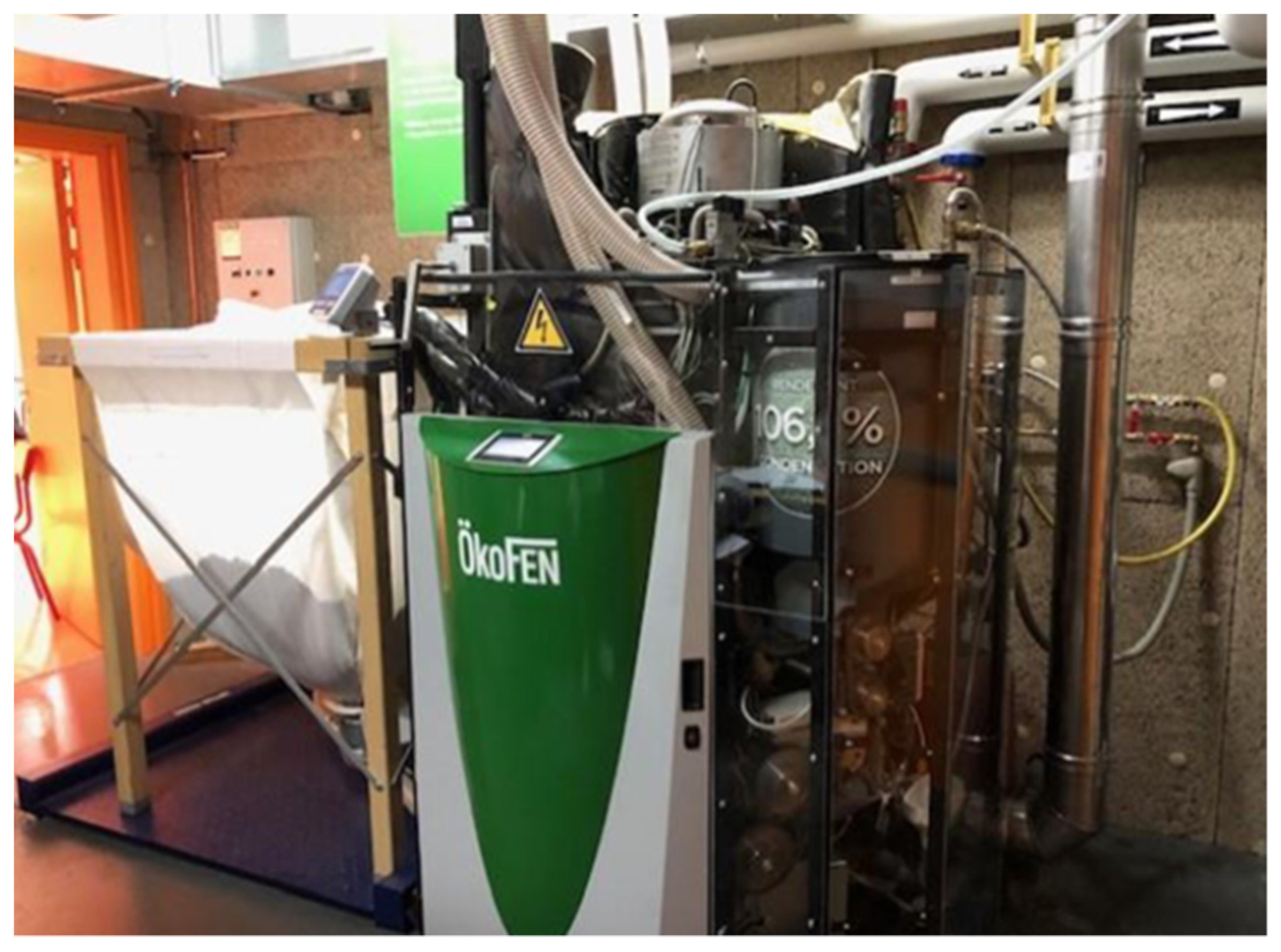
3.3. Micro Combined Heat and Power
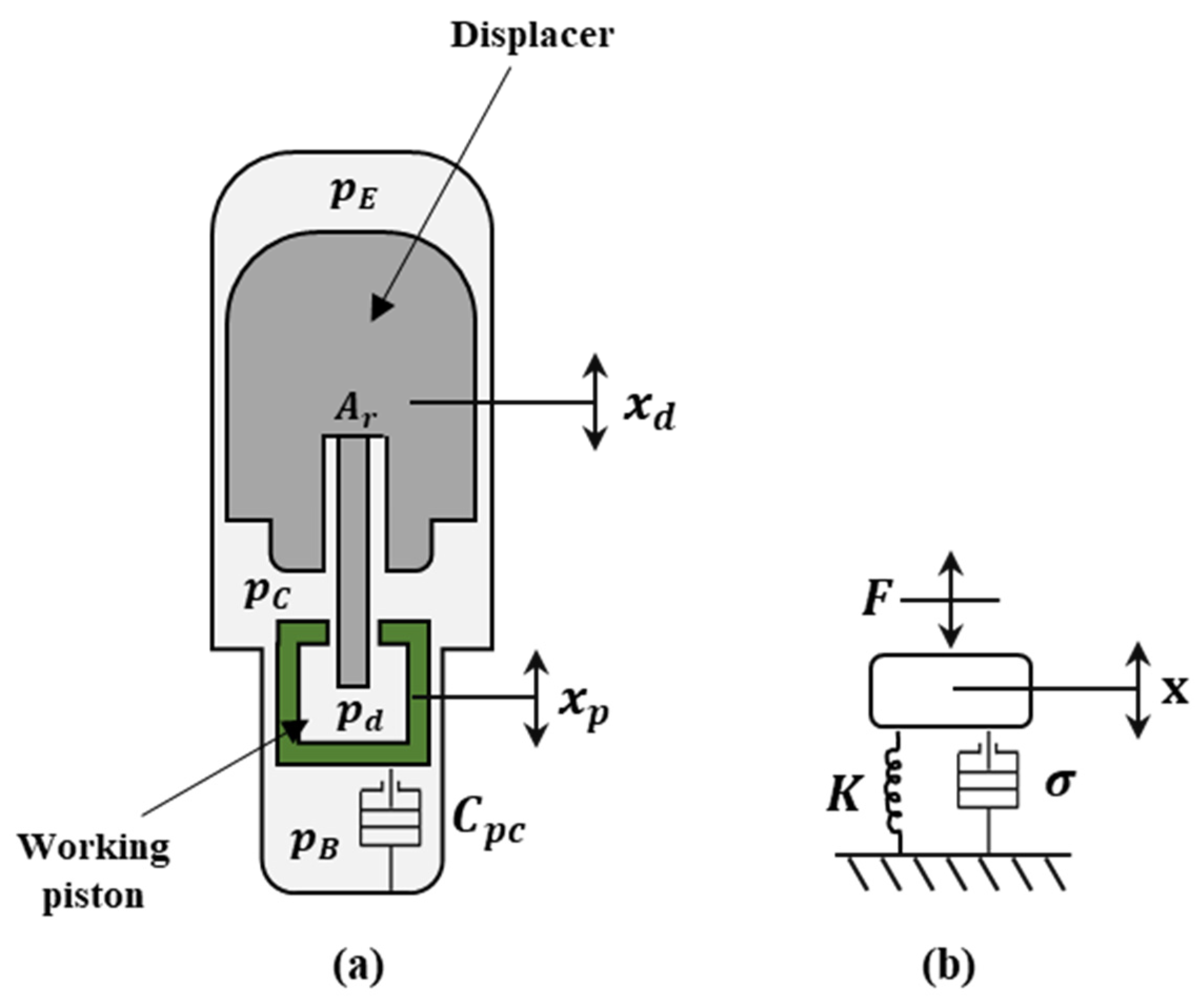
4. Free-Piston Stirling Engine Modeling
5. Conclusions
Author Contributions
Funding
Institutional Review Board Statement
Informed Consent Statement
Data Availability Statement
Conflicts of Interest
Nomenclature
| Acronyms | |
| 1D | One-dimensional |
| 2D | Two-dimensional |
| CFD | Computational Fluid Dynamics |
| CHP | Combined Heat and Power |
| CSP | Concentrated Solar Power |
| FPSE | Free-Piston Stirling Engine |
| ORC | Organic Rankine Cycle |
| SE | Stirling Engine |
| Symbols | |
| Cross-section area (m2) | |
| Cpc | Load damping (Ns/m) |
| CHdc | Displacer gas spring damping (Nsm−1) |
| CHpc | Working piston gas spring damping (Nsm−1) |
| Damping coefficient | |
| Effect of the -component motion on the -component for damping Expansion clearance space (mm) | |
| Frequency (Hz) | |
| Applied force (N) | |
| Damping force (N) | |
| Force due to spring effects (N) | |
| Thermal conductivity (Wm−1K−1) | |
| K | Spring stiffness (Nm−1) |
| Mass (kg) | |
| Pressure (Pa) | |
| Indicated power (W) | |
| pmean | Mean pressure (Pa) |
| Working gas constant (jkg−1K−1) | |
| Stroke (m) | |
| S | Heat exchange surface/stiffness coefficient (m2)/(s−2) |
| Effect of the -component motion on the -component for spring | |
| Time (s) | |
| Temperature (k) | |
| Volume (m3) | |
| Dead volume of the cold space (m3) | |
| Dead volume of the hot space (m3) | |
| Swept volume (m3) | |
| Mechanical power (w) | |
| Dead volume ratio | |
| Displacement (m) | |
| Velocity (ms−1) | |
| Acceleration (ms−2) | |
| Amplitude coefficient (m3K−1) | |
| Greek Symbols | |
| Swept volume phase angle (rad) | |
| Displacer-piston phase angle (rad) | |
| Heat exchanger effectiveness (%) | |
| Swept volume ratio (-) | |
| Damping coefficient (Nsm−1) | |
| Temperature ratio (-) | |
| Angular velocity (rads−1) | |
| Subscripts | |
| Bounce space | |
| Compression space | |
| Compression chamber dead volume | |
| Displacer | |
| Compression side of the displacer/dead volume of the cold space | |
| Expansion side of the displacer | |
| Displacer rod | |
| Expansion space | |
| Heater | |
| Expansion chamber dead volume | |
| Cooler | |
| Working piston | |
| Compression side of the working piston | |
| r | Rod |
| Regenerator | |
| Spring effect | |
| Swept (volume) | |
References
- Walker, G. Stirling Engines; Clarendon Press: Oxford, UK, 1980. [Google Scholar]
- Hachem, H.; Gheith, R.; Aloui, F.; Ben Nasrallah, S. Technological challenges and optimization efforts of the Stirling machine: A review. Energy Convers. Manag. 2018, 171, 1365–1387. [Google Scholar] [CrossRef]
- Kuban, L.; Stempka, J.; Tyliszczak, A. A 3d-CFD study of a γ–type Stirling engine. Energy 2019, 169, 142–159. [Google Scholar] [CrossRef]
- Alfarawi, S.; Al-Dadah, R.; Mahmoud, S. Influence of phase angle and dead volume on gamma-type Stirling engine power using CFD simulation. Energy Convers. Manag. 2016, 124, 130–140. [Google Scholar] [CrossRef]
- Catapano, F.; Perozziello, C.; Vaglieco, B.M. Heat transfer of a Stirling engine for waste heat recovery application from internal combustion engines. Appl. Therm. Eng. 2021, 198, 117492. [Google Scholar] [CrossRef]
- Chahartaghi, M.; Sheykhi, M. Energy, environmental and economic evaluations of a CCHP system driven by Stirling engine with helium and hydrogen as working gases. Energy 2019, 174, 1251–1266. [Google Scholar] [CrossRef]
- Bert, J.; Chrenko, D.; Sophy, T.; le Moyne, L.; Sirot, F. Simulation, experimental validation and kinematic optimization of a Stirling engine using air and helium. Energy 2014, 78, 701–712. [Google Scholar] [CrossRef]
- Ni, M.; Shi, B.; Xiao, G.; Peng, H.; Sultan, U.; Wang, S.; Luo, Z.; Cen, K. Improved simple analytical model and experimental study of a 100 W β-type Stirling engine. Appl. Energy 2016, 169, 768–787. [Google Scholar] [CrossRef]
- Mou, J.; Li, W.; Li, J.; Hong, G. Gas action effect of free piston Stirling engine. Energy Convers. Manag. 2016, 110, 278–286. [Google Scholar] [CrossRef]
- Xiao, G.; Huang, Y.; Wang, S.; Peng, H.; Ni, M.; Gan, Z.; Luo, Z.; Cen, K. An approach to combine the second-order and third-order analysis methods for optimization of a Stirling engine. Energy Convers. Manag. 2018, 165, 447–458. [Google Scholar] [CrossRef]
- Abbas, M.; Boumeddane, B.; Said, N.; Chikouche, A. Dish Stirling technology: A 100 MW solar power plant using hydrogen for Algeria. Int. J. Hydrogen Energy 2011, 36, 4305–4314. [Google Scholar] [CrossRef]
- Renzi, M.; Brandoni, C. Study and application of a regenerative Stirling cogeneration device based on biomass combustion. Appl. Therm. Eng. 2014, 67, 341–351. [Google Scholar] [CrossRef]
- Magri, G.; di Perna, C.; Serenelli, G. Analysis of electric and thermal seasonal performances of a residential microCHP unit. Appl. Therm. Eng. 2012, 36, 193–201. [Google Scholar] [CrossRef]
- Tavakolpour-Saleh, A.; Zare, S.; Bahreman, H. A novel active free piston Stirling engine: Modeling, development, and experiment. Appl. Energy 2017, 199, 400–415. [Google Scholar] [CrossRef]
- Vuarnoz, D.; Kitanovski, A.; Gonin, C.; Borgeaud, Y.; Delessert, M.; Meinen, M.; Egolf, P.W. Quantitative feasibility study of magnetocaloric energy conversion utilizing industrial waste heat. Appl. Energy 2012, 100, 229–237. [Google Scholar] [CrossRef]
- Zare, S.; Tavakolpour-Saleh, A. Free piston Stirling engines: A review. Int. J. Energy Res. 2020, 44, 5039–5070. [Google Scholar] [CrossRef]
- Park, J.; Ko, J.; Kim, H.; Hong, Y.; Yeom, H.; Park, S.; In, S. The design and testing of a kW-class free-piston Stirling engine for microcombined heat and power applications. Appl. Therm. Eng. 2020, 164, 114504. [Google Scholar] [CrossRef]
- Zhu, S.; Yu, G.; Ma, Y.; Cheng, Y.; Wang, Y.; Yu, S.; Wu, Z.; Dai, W.; Luo, E. A free-piston Stirling generator integrated with a parabolic trough collector for thermal-to-electric conversion of solar energy. Appl. Energy 2019, 242, 1248–1258. [Google Scholar] [CrossRef]
- Penswick, L.; Olan, R.W.; Williford, I.; Draney, S.; Buchholz, G. High-capacity and efficiency Stirling cycle cryocooler. Cryocooler 2014, 18, 155–162. [Google Scholar]
- Qiu, S.; Gao, Y.; Rinker, G.; Yanaga, K. Development of an advanced free-piston Stirling engine for micro combined heating and power application. Appl. Energy 2019, 235, 987–1000. [Google Scholar] [CrossRef]
- Breeze, P. Stirling engines and free piston engines. In Piston Engine-Based Power Plants; Academic Press: London, UK, 2018; pp. 59–70. [Google Scholar]
- Harrison, J.; On, E. Stirling engine systems for small and micro combined heat and power (CHP) applications. In Small and Micro Combined Heat and Power (CHP) Systems; Woodhead Publishing: Sawston, UK, 2011; pp. 179–205. [Google Scholar]
- Schiel, W.; Keck, T. Parabolic dish concentrating solar power (CSP) systems. Conc. Sol. Power Technol. 2012, 284–322. [Google Scholar] [CrossRef]
- De la Bat, B.J.G.; Harms, T.M.; Dobson, R.T.; Eng, M.; Bell, A.J. Derivation and numerical case study of a one-dimensional, compressible-flow model of a novel free-piston Stirling engine. Energy 2020, 199, 117404. [Google Scholar] [CrossRef]
- Ye, W.; Yang, P.; Liu, Y. Multi-objective thermodynamic optimization of a free piston Stirling engine using response surface methodology. Energy Convers. Manag. 2018, 176, 147–163. [Google Scholar] [CrossRef]
- Perozziello, C. Experimental and Numerical Study of a Stirling Engine for Waste Heat Recovery from Internal Combustion Engine; University of Naples Parthenope: Napoli, Italy, 2020. [Google Scholar]
- Walker, G.; Senft, J. Lecture Notes in Engineering: Free Piston Stirling Engines, 1st ed.; Springer: Berlin/Heidelberg, Germany, 1985. [Google Scholar]
- Caughley, A.; Sellier, M.; Gschwendtner, M.; Tucker, A. A free-piston Stirling cryocooler using metal diaphgrams. Cryogenics 2016, 80, 8–16. [Google Scholar] [CrossRef]
- Py, X.; Azoumah, Y.; Olives, R. Concentrated solar power: Current technologies, major innovative issues and applicability to west African countries. Renew. Sustain. Energy Rev. 2013, 18, 306–315. [Google Scholar] [CrossRef]
- Khosravi, A.; Syri, S.; Pabon, J.J.; Sandoval, O.R.; Caetano, B.C.; Barrientos, M.H. Energy modeling of a solar dish/Stirling by artificial intelligence approach. Energy Convers. Manag. 2019, 199, 112021. [Google Scholar] [CrossRef]
- Mancini, T.; Heller, P.; Butler, B.; Osborn, B.; Schiel, W.; Goldberg, V.; Buck, R.; Diver, R.; Andraka, C.; Moreno, J. Dish-Stirling systems: An overview of development and status. J. Sol. Energy Eng. 2003, 125, 135–151. [Google Scholar] [CrossRef]
- Singh, U.R.; Kumar, A. Review on solar Stirling engine: Development and performance. Therm. Sci. Eng. Prog. 2018, 8, 244–256. [Google Scholar] [CrossRef]
- Ahmadi, M.H.; Sayyaadi, H.; Hosseinzadeh, H. Optimization of output power and thermal efficiency of solar-dish Stirling engine using finite time thermodynamic analysis. Heat Transf.-Asian Res. 2015, 44, 347–376. [Google Scholar] [CrossRef]
- May, J.R.; Brennan, D.J. Sustainability assessment of Australian electricity generation. Process Saf. Environ. Prot. 2006, 84, 131–142. [Google Scholar] [CrossRef]
- Zayed, M.; Zhao, J.; Du, Y.; Kabeel, A.; Shalaby, S. Factors affecting the thermal performance of the flat plate solar collector using nanofluids: A review. Sol. Energy 2019, 182, 382–396. [Google Scholar] [CrossRef]
- Coventry, J.; Andraka, C. Dish systems for CSP. Sol. Energy 2017, 152, 140–170. [Google Scholar] [CrossRef]
- Barreto, G.; Canhoto, P. Modelling of a Stirling engine with parabolic dish for thermal to electric conversion of solar energy. Energy Convers. Manag. 2017, 132, 119–135. [Google Scholar] [CrossRef]
- Zhu, S.; Yu, G.; Li, X.; Dai, W.; Luo, E. Parametric study of a free-piston Stirling cryocooler capable of providing 350 W cooling power at 80 K. Appl. Therm. Eng. 2020, 174, 115101. [Google Scholar] [CrossRef]
- Walker, G.C.; Senft, J.R. Large free-piston Stirling engines. In Lecture Notes in Engineering; Springer: Berlin/Heidelberg, Germany, 1985; pp. 216–221. [Google Scholar]
- Mikalsen, R. Internal combustion and reciprocating engine systems for small and micro combined heat and power (CHP) applications. Chap.6. In Small and Micro Combined Heat and Power (CHP) Systems; R Beith Woodhead Publishing: Sawston, UK, 2011; pp. 125–146. [Google Scholar]
- Thu, K.; Saha, B.B.; Chua, K.J.; Bui, T.D. Thermodynamic analysis on the part-load performance of a microturbine system for micro/mini-CHP applications. Appl. Energy 2016, 178, 600–608. [Google Scholar] [CrossRef]
- Rist, J.F.; Dias, M.F.; Palman, M.; Zelazo, D.; Cukurel, B. Economic dispatch of a single micro-gas turbine under CHP operation. Appl. Energy 2017, 200, 1–18. [Google Scholar] [CrossRef]
- Oyewunmi, O.; Kirmse, C.J.; Pantaleo, A.; Markides, C. Performance of working-fluid mixtures in ORC-CHP systems for different heat-demand segments and heat-recovery temperature levels. Energy Convers. Manag. 2017, 148, 1508–1524. [Google Scholar] [CrossRef]
- Dong, L.; Liu, H.; Riffat, S. Development of small-scale and micro-scale biomass fueled CHP systems—A literature review. Appl. Therm. Eng. 2009, 29, 2119–2126. [Google Scholar] [CrossRef] [Green Version]
- Staffell, I.; Green, R. The cost of domestic fuel cell micro-CHP systems. Int. J. Hydrogen Energy 2013, 38, 1088–1102. [Google Scholar] [CrossRef] [Green Version]
- Bartela, Ł.; Kotowicz, J.; Dubiel-Jurgaś, K. Investment risk for biomass integrated gasification combined heat and power unit with an internal combustion engine and a Stirling engine. Energy 2018, 150, 601–616. [Google Scholar] [CrossRef]
- Qiu, S.; Solomon, L.; Rinker, G. Development of an integrated thermal energy storage and free-piston Stirling generator for a concentrating solar power system. Energies 2017, 10, 1361. [Google Scholar] [CrossRef] [Green Version]
- Available online: https://www.microgen-engine.com/ (accessed on 15 September 2020).
- Available online: https://www.qnergy.com/ (accessed on 15 September 2020).
- Mahkamov, K. Thermal-engine-based small and micro combined heat and power (CHP) systems for domestic applications: Modelling micro-CHP deployment. Chap.18. In Small and Micro Combined Heat and Power (CHP) Systems; R BeithWoodhead Publishing: Sawston, UK, 2011; pp. 459–509. [Google Scholar]
- Available online: http://www.oekofen-e.com/en/engine/ (accessed on 15 September 2020).
- De la Bat, B.J.G.; Dobson, R.T.; Harms, T.M.; Bell, A.J. Simulation, manufacture and experimental validation of a novel single-acting free-piston Stirling engine electric generator. Appl. Energy 2020, 263, 114585. [Google Scholar] [CrossRef]
- Cardozo, E.; Erlich, C.; Malmquist, A.; Alejo, L. Integration of a wood pellet burner and a Stirling engine to produce residential heat and power. Appl. Therm. Eng. 2014, 73, 671–680. [Google Scholar] [CrossRef]
- Zhu, S.; Yu, G.; Jongmin, O.; Xu, T.; Wu, Z.; Dai, W.; Luo, E. Modeling and experimental investigation of a free-piston Stirling engine-based micro-combined heat and power system. Appl. Energy 2018, 226, 522–533. [Google Scholar] [CrossRef]
- Qiu, S.; Solomon, L. Free-piston stirling engine generators. In Energy Conversion—Current Technologies and Future Trends; IntechOpen: London, UK, 2018; Available online: https://www.intechopen.com/chapters/62541 (accessed on 15 September 2020). [CrossRef] [Green Version]
- Mraz, S.J. Infinia Uses Stirling Cycle for Solar Power and Air Conditioning. Available online: http://machinedesign.com/energy/infinia-uses-stirling-cycle-solar-power-and-air-conditioning (accessed on 11 August 2011).
- Available online: www.qnergy.com/wp-content/uploads/2017/12/Download-the-PCK80-Brochure-SpecSheet.pdf (accessed on 4 October 2020).
- Ferreira, A.C.; Silva, J.; Teixeira, S.; Teixeira, J.; Nebra, S.A. Assessment of the Stirling engine performance comparing two renewable energy sources: Solar energy and biomass. Renew. Energy 2020, 154, 581–597. [Google Scholar] [CrossRef]
- Mazzetti, A.; Pret, M.G.; Pinarello, G.; Celotti, L.; Piskacev, M.; Cowley, A. Heat to electricity conversion systems for moon exploration scenarios: A review of space and ground technologies. Acta Astronaut. 2019, 156, 162–186. [Google Scholar] [CrossRef]
- Available online: https://www.oekofen.com/ (accessed on 4 October 2020).
- Available online: http://www.okofen-e.com/en/pellematic_condens_e/ (accessed on 4 October 2020).
- Available online: http://www.okofen-e.com/en/pellematic_e_max/ (accessed on 4 October 2020).
- Martini, W.R. Stirling Engine Design Manual; US Department of Energy: Washington, DC, USA, 1978.
- Finkelstein, T. Insights into the thermodynamics of Stirling cycle machines. In Proceedings of the Intersociety Energy Conversion Engineering Conference, Monterey, CA, USA, 7–11 August 1994; pp. 1829–1834. [Google Scholar]
- Urieli, I.; Berchowitz, D.M. Stirling Cycle Engine Analysis; Adam Hilger Ltd.: Bristol, NY, USA, 1984. [Google Scholar]
- Li, R.; Grosu, L.; Queiros-Condé, D. Losses effect on the performance of a gamma type Stirling engine. Energy Convers. Manag. 2016, 114, 28–37. [Google Scholar] [CrossRef]
- Li, R.; Grosu, L.; Li, W. New polytropic model to predict the performance of beta and gamma type Stirling engine. Energy 2017, 128, 62–76. [Google Scholar] [CrossRef]
- Grosu, L.; Dobre, C.; Petrescu, S. Study of a Stirling engine used for domestic micro-cogeneration. Thermodynamic analysis and experiment. Int. J. Energy Res. 2015, 39, 1280–1294. [Google Scholar] [CrossRef]
- Cheng, C.-H.; Yu, Y.-J. Numerical model for predicting thermodynamic cycle and thermal efficiency of a beta-type Stirling engine with rhombic-drive mechanism. Renew. Energy 2010, 35, 2590–2601. [Google Scholar] [CrossRef]
- Araoz, J.A.; Cardozo, E.; Salomon, M.; Alejo, L.; Fransson, T.H. Development and validation of a thermodynamic model for the performance analysis of a gamma Stirling engine prototype. Appl. Therm. Eng. 2015, 83, 16–30. [Google Scholar] [CrossRef] [Green Version]
- Ahmadi, M.H.; Ahmadi, M.-A.; Pourfayaz, F. Thermal models for analysis of performance of Stirling engine: A review. Renew. Sustain. Energy Rev. 2017, 68, 168–184. [Google Scholar] [CrossRef]
- Toghyani, S.; Kasaeian, A.; Hashemabadi, S.H.; Salimi, M. Multi-objective optimization of GPU3 Stirling engine using third order analysis. Energy Convers. Manag. 2014, 87, 521–529. [Google Scholar] [CrossRef]
- Hooshang, M.; Moghadam, R.A.; Nia, S.A.; Masouleh, M.T. Optimization of Stirling engine design parameters using neural networks. Renew. Energy 2015, 74, 855–866. [Google Scholar] [CrossRef]
- Ahmadi, M.H.; Hosseinzade, H.; Sayyaadi, H.; Mohammadi, A.H.; Kimiaghalam, F. Application of the multi-objective optimization method for designing a powered Stirling heat engine: Design with maximized power, thermal efficiency and minimized pressure loss. Renew. Energy 2013, 60, 313–322. [Google Scholar] [CrossRef]
- Li, R.; Grosu, L.; Queiros-Conde, D. Multi-objective optimization of Stirling engine using finite physical dimensions thermodynamics. Energy Convers. Manag. 2016, 124, 517–527. [Google Scholar] [CrossRef]
- Xiao, G.; Sultan, U.; Ni, M.; Peng, H.; Zhou, X.; Wang, S.; Luo, Z. Design optimization with computational fluid dynamic analysis of beta-type Stirling engine. Appl. Therm. Eng. 2017, 113, 87–102. [Google Scholar] [CrossRef]
- Formosa, F. Coupled thermodynamic–dynamic semi-analytical model of free piston Stirling engines. Energy Convers. Manag. 2011, 52, 2098–2109. [Google Scholar] [CrossRef] [Green Version]
- Rogdakis, E.; Bormpilas, N.; Koniakos, I. A thermodynamic study for the optimization of stable operation of free piston Stirling engines. Energy Convers. Manag. 2004, 45, 575–593. [Google Scholar] [CrossRef]
- Benvenuto, G.; de Monte, F. A simple approach to calculate the regenerator effectiveness in Stirling Machines. In Proceedings of the 7th International Conference on Stirling Cycle Machines, Waseda University, Tokyo, Japan, 5–8 November 1995. [Google Scholar]
- Rogdakis, E.D.; Bormpilas, N.A.; Koniakos, I.K. A thermodynamic study of the thermal performance of free piston stirling prime movers. Saf. Eng. Risk Anal. 2002, 2002, 19–27. [Google Scholar] [CrossRef]
- Formosa, F.; Despesse, G. Analytical model for Stirling cycle machine design. Energy Convers. Manag. 2010, 51, 1855–1863. [Google Scholar] [CrossRef] [Green Version]
- Kwankaomeng, S.; Silpsakoolsook, B.; Savangvong, P. Investigation on stability and performance of a free-piston Stirling engine. Energy Procedia 2014, 52, 598–609. [Google Scholar] [CrossRef] [Green Version]
- Tavakolpour-Saleh, A.; Zare, S.; Omidvar, A. Applying perturbation technique to analysis of a free piston Stirling engine possessing nonlinear springs. Appl. Energy 2016, 183, 526–541. [Google Scholar] [CrossRef]
- Sowale, A.; Anthony, E.J.; Kolios, A.J. Optimisation of a quasi-steady model of a free-piston Stirling engine. Energies 2018, 12, 72. [Google Scholar] [CrossRef] [Green Version]
- Available online: https://core.ac.uk/reader/77062392 (accessed on 10 October 2020).
- Gedeon, D. Sage User’s Guide: Stirling, Pulse-Tube and Low-T Cooler Model Classes, 11th ed.; Gedeon Associates: Athens, Greece, 2016. [Google Scholar]
- Chi, C.; Mou, J.; Lin, M.; Hong, G. CFD simulation and investigation on the operating mechanism of a beta-type free piston Stirling engine. Appl. Therm. Eng. 2020, 166, 114751. [Google Scholar] [CrossRef]
- Prinsloo, G.; Dobson, R.; Mammoli, A. Model based design of a novel Stirling solar micro-cogeneration system with performance and fuel transition analysis for rural African village locations. Sol. Energy 2016, 133, 315–330. [Google Scholar] [CrossRef]
- Hassan, A.; Torres-Perez, A.; Kaczmarczyk, S.; Picton, P. Vibration control of a Stirling engine with an electromagnetic active tuned mass damper. Control. Eng. Pract. 2016, 51, 108–120. [Google Scholar] [CrossRef]
- Remiorz, L.; Kotowicz, J.; Uchman, W. Comparative assessment of the effectiveness of a free-piston Stirling engine-based micro-cogeneration unit and a heat pump. Energy 2018, 148, 134–147. [Google Scholar] [CrossRef]
- González-Pino, I.; Perez-Iribarren, E.; Campos-Celador, A.; Terés-Zubiaga, J. Analysis of the integration of micro-cogeneration units in space heating and domestic hot water plants. Energy 2020, 200, 117584. [Google Scholar] [CrossRef]
- Qiu, S.; Peterson, A. Linear dynamic modeling and numerical simulation of an STC Stirling convertor. In Proceedings of the 1st International Energy Conversion Engineering Conference (IECEC), Portsmouth, VA, USA, 17–21 August 2003. [Google Scholar]
- Demko, R.; Penswick, L. Sage simulation model for technology demonstration convertor by a step-by-step approach. In Proceedings of the 3rd International Energy Conversion Engineering Conference (IECEC), San Francisco, CA, USA, 15–18 August 2005. [Google Scholar]
- Roth, M.E.; Schreiber, J.; Pepper, S. Extended operation of stirling convertors. In Proceedings of the 2nd International Energy Conversion Engineering Conference (IECEC), Providence, RI, USA, 16–19 August 2004. [Google Scholar]
- Bagg, S.D. Linear alternator technologies used for free piston Stirling engine. In Proceedings of the Nuclear and Emerging Technologies for Space, Woodlands, TX, USA, 21–23 March 2012. [Google Scholar]
- Qiu, S.; Redinger, D.; Augenblick, J. The new generation infinia free-piston Stirling engine for micro-CHP and remote power applications. In Proceedings of the 3rd International Energy Conversion Engineering Conference (IECEC), San Francisco, CA, USA, 15–18 August 2005. [Google Scholar]
- Li, R.; Qiu, S.; Gao, Y. Development of an advanced free piston Stirling engine of space power system. In Proceedings of the AIAA Propulsion and Energy 2019 Forum, Indianapolis, IN, USA, 9–22 August 2019. [Google Scholar]
- Li, R.; Gao, Y.; Yanaga, K.; Qiu, S. Design of a free piston Stirling engine power generator. In Proceedings of the ASME International Mechanical Engineering Congress and Exposition, Salt Lake City, UT, USA, 11–14 November 2019. [Google Scholar]


| Micro-CHP Unit | FPSE Manufacturer | Heat Source | Thermal Input (kW) | Electric Power (kW) | Thermal Output (kW) | Flame Temperature (K) |
|---|---|---|---|---|---|---|
| Pellematic Condense | Microgen | Wood pellets | 10 | 0.7 | 7.9 | 950 |
| Parameters | Urieli et al. [65] | Walker et al. [27] | Rogdakis [80] | Rogdakis [78] | Exper. [65] |
|---|---|---|---|---|---|
| Frequency (Hz) | 33.2 | 32.9 | 32.9 | 30 | 30 |
| Phase angle (°) | −57.9 | −55.1 | −55.1 | −54.8 | −42.5 |
| Amplitude ratio | 0.62 | 0.63 | 0.63 | 0.87 | 1.06 |
| Authors | Model Type/Analysis Methods | Main Points |
|---|---|---|
| Rogdakis et al. [78] | Thermodynamic model | The dynamic balance equations are solved using a linearization technique. |
| Formosa and Despesse [81] | Thermodynamic model | The irreversibility of the heat exchangers and regenerator is expressed as a function of fluid flow rates. |
| Formosa [77] | Semi-analytical dynamic model | A coupled iterative technique solves the isothermal and the dynamic analysis. |
| Kwankaomeng et al. [82] | Thermodynamic and dynamic model | The isothermal analysis is combined with the approximation of the engine to a mass-spring-damper system, assuming harmonic motion of the pistons. |
| Tavakolpour-Saleh et al. [83] | Nonlinear analysis | The multiple-scale method uses two independent variables (fast-scale and slow-scale type), taking into account the nonlinear springs in the engine. |
| Sowale et al. [84,85] | 1D quasi-steady model | Damping and spring stiffness is calculated at each iteration, until convergence criteria is reached. |
| Ye et al. [25] | Multi-objective optimization | The response surface methodology (RSM) determines the optimal combination of the engine parameters. |
| Zhu et al. [54] | Thermo-acoustic analogy | The frequency and the piston displacement are solved implicitly using the thermo-acoustic theory. |
| Demko et al. [93] | Sage 1D model | The engine is simulated increasing the number of components, until reaching a more real model as possible. |
Publisher’s Note: MDPI stays neutral with regard to jurisdictional claims in published maps and institutional affiliations. |
© 2021 by the authors. Licensee MDPI, Basel, Switzerland. This article is an open access article distributed under the terms and conditions of the Creative Commons Attribution (CC BY) license (https://creativecommons.org/licenses/by/4.0/).
Share and Cite
Perozziello, C.; Grosu, L.; Vaglieco, B.M. Free-Piston Stirling Engine Technologies and Models: A Review. Energies 2021, 14, 7009. https://doi.org/10.3390/en14217009
Perozziello C, Grosu L, Vaglieco BM. Free-Piston Stirling Engine Technologies and Models: A Review. Energies. 2021; 14(21):7009. https://doi.org/10.3390/en14217009
Chicago/Turabian StylePerozziello, Carmela, Lavinia Grosu, and Bianca Maria Vaglieco. 2021. "Free-Piston Stirling Engine Technologies and Models: A Review" Energies 14, no. 21: 7009. https://doi.org/10.3390/en14217009